

Page 1
OPTIONS
D BATTERY PACKS
• BP-283 Li-ion BATTERY PACK
Voltage: 7.2 V
Capacity: 1910 mAh (minimum), 2010 mAh (typical)
Battery life: Approximately 9 hours
• BP-284
Voltage: 7.2 V
Capacity: 3070 mAh (minimum), 3210 mAh (typical)
Battery life: Approximately 14 hours*
*1
When the power save function is set to “Short,” and the
operating periods are calculated under the following
conditions:
TX : RX : standby = 5 : 5 : 90
D CHARGERS
• BC-219 DESKTOP CHARGER + BC-123S AC ADAPTER
For rapidly charging battery packs.
Charging time: Approximately 2.8 hours for the BP-283
A power adapter may be supplied, depending on the charger’s
version.
• BC-214 MULTI-CHARGER
+ BC-157S AC ADAPTER, OPC-656 DC POWER CABLE
For rapidly charging of up to 6 battery packs
simultaneously.
Charging time: Approximately 2.8 hours for the BP-283
The AD-132 CHARGER ADAPTER may be needed, depending on
the charger's version.
The BC-157S AC ADAPTER or OPC-656 DC POWER CABLE must
be purchased separately.
• BC-225 INTELLIGENT DESKTOP CHARGER + BC-123S AC
ADAPTER
+ RS-BC225 READER SOFTWARE
For rapidly charging of battery packs.
You can check the charging status using the RS-BC225.
Charging time: Approximately 2.5 hours for the BP-283
A power adapter may be supplied, depending on the charger’s
version.
An USB (Micro-B) cable is required to connect the BC-225 and
a PC with the RS-BC225 installed.
D DC CABLES
• CP-23L CIGARETTE LIGHTER CABLE
Used when charging battery packs through a 12 V
cigarette lighter socket. For use with the BC-219.
• OPC-515L, OPC-656
Used when charging battery packs using a 13.8 V DC
power source instead of the power adapter.
OPC-515L: For the BC-219
OPC-656: For the BC-214
D BELT CLIPS and BELT HANGERS
• MB-133 BELT CLIP
• MB-136 BELT CLIP
Rotating type.
• MB-96F, MB-96FL, MB-96N
(IC-F7010T/IC-F7010S)
Li-ion BATTERY PACK
1
(IC-F7010T/IC-F7010S)
DC POWER CABLES
BELT HANGERS
D ANTENNAS
• FA-S81VS, FA-S82VS, FA-S83VS,
FA-S81US, FA-S82US
Shorter VHF or UHF antennas.
FA-S81VS: 136 ~ 150 MHz FA-S82VS: 150 ~ 162 MHz
FA-S83VS: 160 ~ 174 MHz FA-S81US: 400 ~ 450 MHz
FA-S82US: 450 ~ 490 MHz
• FA-S81V, FA-S82V, FA-S83V,
FA-S81U, FA-S82U, FA-S83U
VHF or UHF antennas.
FA-S81V: 136 ~ 150 MHz FA-S82V: 148 ~ 160 MHz
FA-S83V: 160 ~ 174 MHz FA-S81U: 380 ~ 430 MHz
FA-S82U: 430 ~ 480 MHz FA-S83U: 470 ~ 520 MHz
• FA-S67VC, FA-S76UC
FA-S67VC: 136 ~ 174 MHz FA-S76UC: 380 ~ 520 MHz
STUBBY ANTENNAS
FLEXIBLE ANTENNAS
CUT ANTENNAS
D OTHERS
• AD-118 ACC ADAPTER
To connect an accessory. See the AD-118 instruction
sheet for details of recommended accessories.
CAUTION: The AD-118 does not have waterproof
protection. When it is connected, NEVER expose the
adaptor and the transceiver to rain, snow or any liquids.
• LC-184
For the Simple key types and Ten-key types.
• VS-4MC
+ HS-94, HS-95, HS-97 HEADSET
VS-4MC: Used to connect a headset to a transceiver.
HS-94: Ear-hook type
HS-95: Neck-arm type
HS-97: Throat microphone
*2
• HM-222
With an Emergency key.
The HM-222 meets IP68 requirements for waterproof
protection.
• VS-3 Bluetooth
The Bluetooth® headset with a [PTT] switch.
• About the third party Bluetooth
Icom has checked the PTT operation with some 3M Peltor
headsets such as the WS Headset XP, WS ProTac XP and
WS Alert XP. (Compatibility not guaranteed.)
Some options may not be available in some countries.
Ask your dealer for details.
Icom, Icom Inc. and the Icom logo are registered trademarks of Icom Incorporated (Japan) in Japan, the United States, the United Kingdom, Germany, France, Spain, Russia, Australia, New Zealand, and/or other countries.
The Bluetooth word mark and logos are registered trademarks owned by
the Bluetooth SIG, Inc. and any use of such marks by Icom Inc. is under
license. Other trademarks and trade names are those of their respective
owners.
All other products or brands are registered trademarks or trademarks of
their respective holders.
CARRYING CASE
*2
PTT SWITCH CABLE
Non-waterproof.
SPEAKER MICROPHONE
®
HEADSET
®
headsets:
INSTRUCTIONS
VHF P25 TRANSCEIVERS
Iç-F7010T/Iç-F7010S
UHF P25 TRANSCEIVERS
Iç-F7020T/Iç-F7020S
IMPORTANT
This instruction sheet includes some functions that are
usable only when they are preset by your dealer. The
transceiver may have other functions and operations that
are not described in this instruction sheet. Ask your dealer
for preset function details.
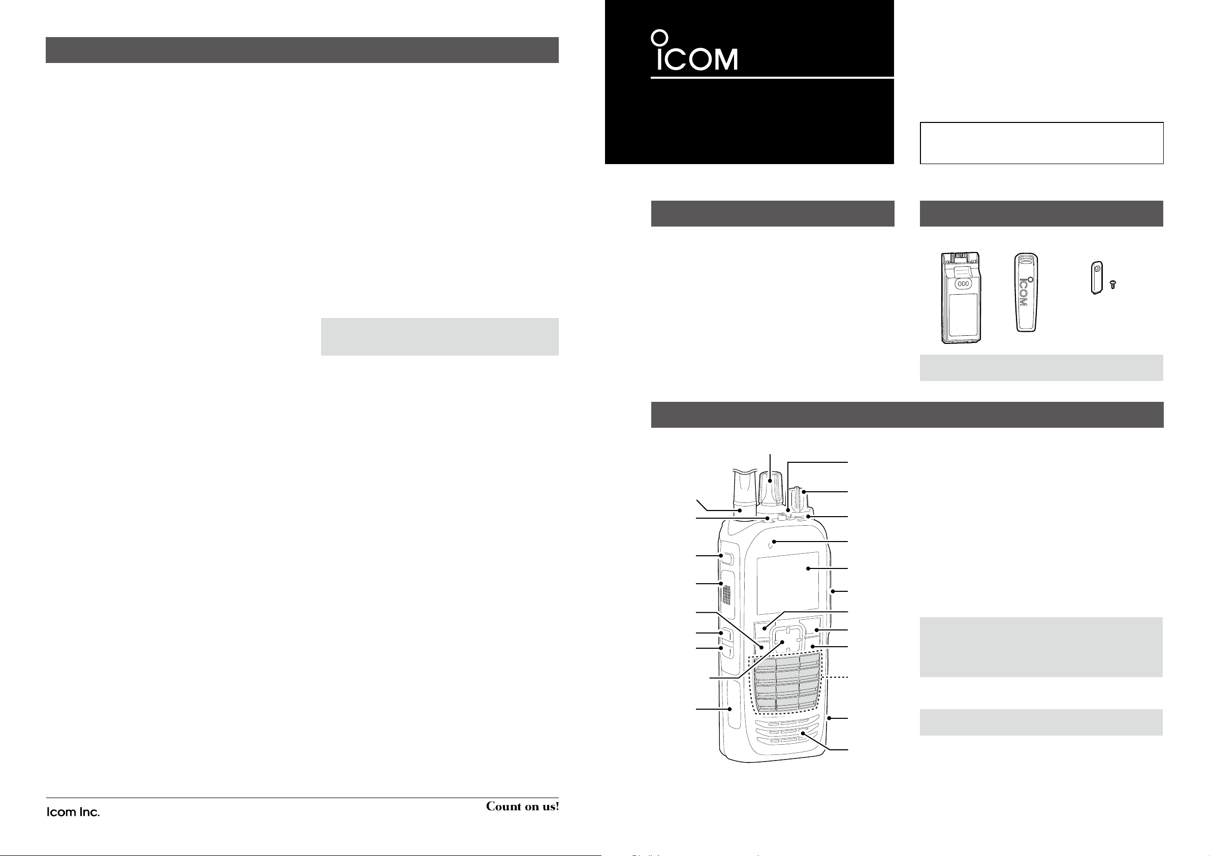
PANEL DESCRIPTION
[Selector]
Lever
Antenna
Connector
[Emer]
[F1]
[PTT]
[OK]
[F2]
[F3]
[Up]/[Down]
[Right]/[Left]
USB
(Micro-B)
Connector
The illustration is of the Ten-key type transceiver.
Switch
[VOL]
Status
indicator
Microphone
Function
Display
Multiconnector
[P1]
[P2]
[Back]
Ten-Key
Pad
microSD
Card Slot
Speaker
Thank you for choosing this Icom product.
READ ALL INSTRUCTIONS carefully and completely
before using this product.
SUPPLIED ACCESSORIES
Battery pack Belt clip Connector cover
(with a screw)
NOTE: Some accessories are not supplied, or the shape
is different, depending on the transceiver version.
D About the transceiver types
There are 2 types of transceivers.
IC-F7010S, IC-F7020S: Simple key types
IC-F7010T, IC-F7020T: Ten-key types
D About the Status indicator
• Lights blue, then blinks red, yellow, and green when
turning ON the transceiver.
• Lights red while transmitting.
• Lights green while receiving a signal, or when the squelch
is open.
• Blinks magenta when the battery is exhausted.
D About the Multi-connector
Connects to an optional speaker microphone or headset.
CAUTION:
connector cover
The transceiver meets IP68 requirements for dust-tight and
waterproof protection only when the connector cover or the
optional HM-222 is attached.
D About the Software key functions
NOTE: Your dealers can assign the Software key
functions to the keys, keypads, and the Lever switch.
DO NOT use the transceiver without the
or the optional equipment attached.
1-1-32 Kamiminami, Hirano-ku, Osaka 547-0003, Japan
- 4 -
A-7377H-1EX Printed in Japan
© 2017 Icom Inc.
- 1 -
Page 2
FUNCTION DISPLAY
BASIC OPERATION
q w
e
Icon Area
Text Area
Key Display
Area
NOTE: The screen capture is an example.
The displayed position of each icon may differ, depending
on the function being used.
D Icon Area
Indicators
q SIGNAL STRENGTH INDICATOR
Displays the relative receive signal strength level.
w CLOCK
Displays the current time.
“AM” or “PM” is displayed beside the time display when 12
hour display format is selected.
e BATTERY INDICATOR
Displayed or blinks to indicate the battery status.
Indication
Battery
status
blinks when the battery is exhausted.
Full Mid
Icons
The following icons are displayed in the Icon Area.
POWER ICON
• “L1” is displayed when the output power is set to Low.
• “L2” is displayed when the output power is set to Mid.
• “H” is displayed when the output power is set to High.
AUDIBLE ICON
Displayed when the channel is in the ‘audible’ (unmute)
mode.
MESSAGE ICON
• Blinks after messages (Message or Status Message) have been
received.
• Stops blinking when the screen is changed, or any key is pushed,
but is displayed if unread messages are still in the Message
memory.
• Disappears when all messages in the Message memory have
been read.
BELL ICON
Displayed when a matching signal is received, depending
on the presetting.
Charging
required
Battery
exhausted
SCRAMBLER ICON
In the Analog mode:
Displayed when the Voice Scrambler function is ON.
GPS ICON
• Displayed when valid position data is received.
• Blinks when searching for satellites or calculating position data.
RECORD ICON
• Displayed when the Record function is ON.
• Blinks while recording audio.
“ ”
is displayed when there is no microSD card free space and
audio cannot be recorded.
TALK AROUND ICON
Displayed when the Talk Around function is ON.
PHONE ICON
• Displayed when the transceiver is connected to a telephone
network on the selected channel.
• Blinks while receiving a phone call.
LONE WORKER ICON
Displayed when the Lone Worker function is ON.
MOTION SENSOR ICON
Displayed when the Motion Sensor function is ON.
NOISE CANCEL ICON
Displayed when the Noise Cancel function is ON.
SURVEILLANCE ICON
Displayed when the Surveillance function is ON.
VIBRATION ICON
Displayed when the Vibration function is ON.
VOX ICON
Displayed when the VOX function is ON.
®
Bluetooth
• Displayed when Bluetooth® is activated.
• Lights Blue when a Bluetooth® device is connected.
• Does not light when no Bluetooth® device is connected.
ICON
microSD ICON
Displayed when a microSD card is inserted into the card slot.
“ ”
is displayed when the microSD card has not been formatted.
USB ICON
Displayed when a USB device is connected.
D Text Area
Displays the selected Zone number, Channel number, and
Channel name, if set.
D Key Display Area
Displays the names of the function assigned to [P1] and [P2].
Ask your dealer about the assigned Software key functions.
D Turning ON the transceiver
NOTE: Before using the transceiver for the fi rst time, the
battery pack must be fully charged for optimum life and
operation. See the BATTERY CHARGING section of this
sheet.
Rotate [VOL] to turn ON the transceiver.
Transmitting:
CAUTION: Attach an antenna before transmitting.
Transmitting without an antenna may damage the
transceiver.
1. Wait until the channel is clear to avoid interference.
2. While holding down [PTT], speak at your normal voice
level.
D Receiving and Transmitting
Receiving:
1. Select a channel.
• Rotate [Selector] or push [Up] or [Down], depending
on the presetting.
2. When receiving a call, rotate [VOL] to adjust the audio
output level to a comfortable listening level.
3. Release [PTT] to receive.
IMPORTANT:
To maximize the readability of your signal:
1. After pushing [PTT], pause briefl y before you start
speaking.
2. Hold the microphone 5 to 10 cm (2 to 4 inches) from
your mouth, then speak at your normal voice level.
BATTERY CHARGING
NOTE:
• Before detaching or attaching a battery pack, BE SURE to turn OFF the transceiver by rotating [VOL] fully counter clockwise, until it makes a
“click” sound. Otherwise, a transceiver malfunction could occur.
•
The internal clock will be reset to 00:00 if an exhausted battery is left in the transceiver, or the battery pack is detached, for long periods of time.
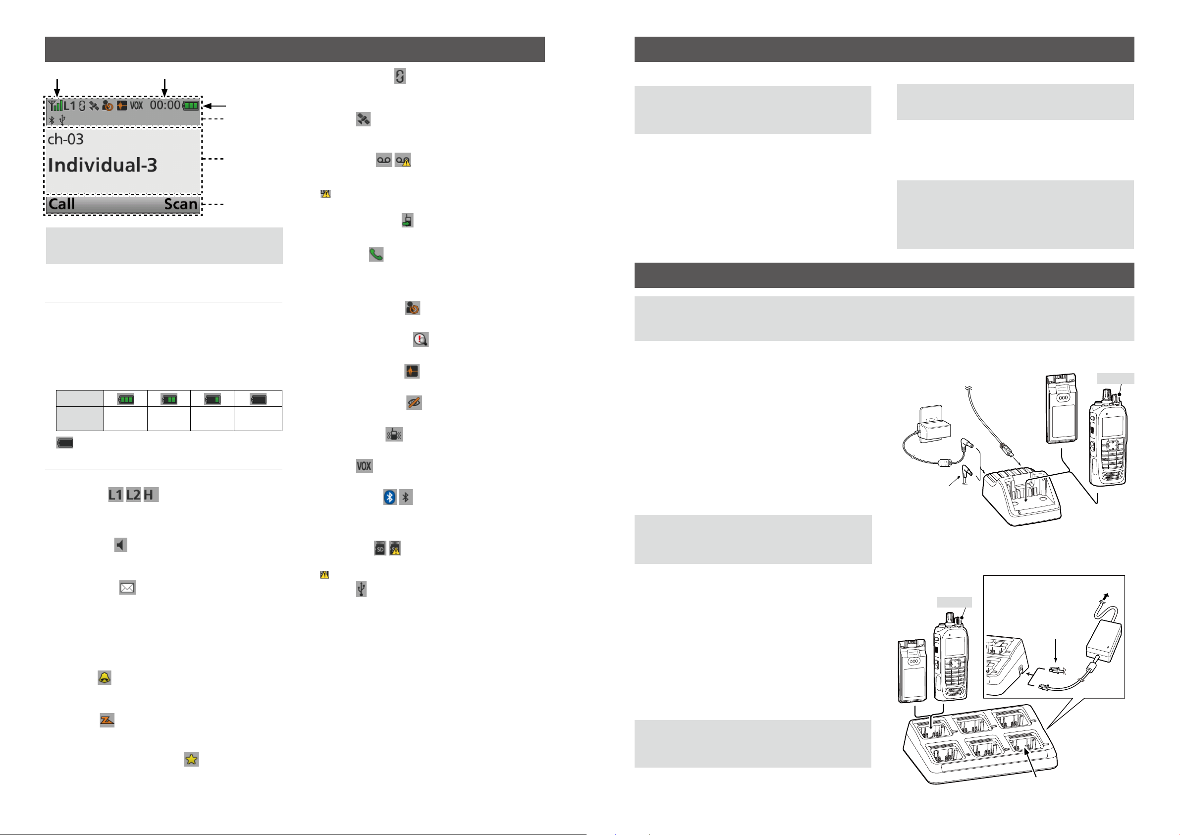
D Rapid charging with the BC-219/BC-225
You can rapidly charge the Li-ion battery pack with the
BC-219 or BC-225.
Charging time:
BC-219: 2.8 hours for the BP-283
BC-225: 2.5 hours for the BP-283
Additionally needed item (purchase separately):
• A power adapter (may be supplied with the charger,
depending on the charger version) or the OPC-515L/CP-23L DC
POWER CABLES.
• A USB cable to connect the PC and BC-225 when using the RSBC225.
CAUTION: NEVER reverse the polarity when connecting
the OPC-515L to a power source. This will ruin the battery
charger.
White line: +, Black line: _
D Rapid charging with the BC-214
You can rapidly charge up to 6 battery packs with the
optional BC-214.
Charging time:
Approximately 2.8 hours for the BP-283
Additionally needed items (purchase separately):
• The BC-157S AC ADAPTER or the OPC-656 DC POWER CABLE
• The AD-132 CHARGER ADAPTER (may be supplied with the
charger, depending on the charger version)
Power Adapter*
The OPC- 515L
( for a 13.8 V DC
power source) or the
CP-23L (for a 12 V
cigarette lighter
socket) can be
used instead of the
power adapter.
Battery pack
+ Transceiver
Battery pack
To a PC with
the RS-BC225
installed.*
2
Turn OFF
1
1
*
The RS-BC225 is usable for only with the
BC-225.
2
*
A different type, or no power adapter is
supplied, depending on the charger version.
Battery Pack
OPC-656
Connect to a
DC power supply:
12 to 16 V, at least 7 A
Red line: +
Black line: _
Battery Pack
+ Transceiver
Turn OFF
To an AC outlet
BC-157S
SCAN ICON
• Displayed when a scan is paused.
• Blinks while scanning.
SCAN TARGET CHANNEL ICON
Displayed when the channel is selected as a scan target channel.
- 2 -
CAUTION: NEVER reverse the polarity when connecting
the OPC-656 to a power source. This will ruin the battery
charger.
Red line: +, Black line: _
BC-214
* Charger adapter’ s shape may differ,
depending on the charger version.
- 3 -
Page 3

• FOR CLASS A UNINTENTIONAL RADIATORS:
This equipment has been tested and found to comply with
the limits for a Class A digital device, pursuant to part 15
of the FCC Rules. These limits are designed to provide
reasonable protection against harmful interference when
the equipment is operated in a commercial environment.
This equipment generates, uses, and can radiate radio
frequency energy and, if not installed and used in
accordance with the instruction manual, may cause harmful
interference to radio communications. Operation of this
equipment in a residential area islikely to cause harmful
interference in which case the user will be required to
correct the interference at his own expense.
CAUTION: Changes or modifi cations to this transceiver,
not expressly approved by Icom Inc., could void
your authority to operate this transceiver under FCC
regulations.
This device complies with Part 15 of the FCC Rules.
Operation is subject to the condition that this device does
not cause harmful interference.
VOICE CODING TECHNOLOGY
The AMBE+2™ voice coding Technology embodied in this
product is protected by intellectual property rights including
patent rights, copyrights and trade secrets of Digital Voice
Systems, Inc. This voice coding Technology is licensed
solely for use within this Communications Equipment.
The user of this Technology is explicitly prohibited from
attempting to extract, remove, decompile, reverse engineer,
or disassemble the Object Code, or in any other way
convert the Object Code into a human-readable form. U.S.
Patent Nos.
#5,870,405, #5,826,222, #5,754,974, #5,701,390,
#5,715,365, #5,649,050, #5,630,011, #5,581,656,
#5,517,511, #5,491,772, #5,247,579, #5,226,084 and
#5,195,166.
Icom, Icom Inc. and the Icom logo are registered trademarks
of Icom Incorporated (Japan) in Japan, the United States, the
United Kingdom, Germany, France, Spain, Russia, Australia, New
Zealand, and/or other countries.
AMBE+2 is a trademark and property of Digital Voice Systems Inc.
All other products or brands are registered trademarks or
trademarks of their respective holders.
ABOUT GPS/GLONASS
RECEIVER
An internal GPS or GLONASS receiver may not work if the
transceiver transmits or receives in the frequency ranges
as shown below. This problem is made in the internal circuit
and does not indicate a transceiver malfunction.
For the IC-F7010T/IC-F7010S (Unit: MHz)
GPS receiver GLONASS receiver
Transmit
Receive 146.845 ~ 147.110 149.745 ~ 150.790
For the IC-F7020T/IC-F7020S (Unit: MHz)
Transmit
Receive 443.545 ~ 444.065
CLEAN THE TRANSCEIVER THOROUGHLY WITH
FRESH WATER after exposure to saltwater, and dry
it before operating. Otherwise, the transceiver's keys,
switches and controllers may become unusable, due to salt
crystallization, and/or the charging terminals of the battery
pack may rust.
NOTE: If the transceiver’s waterproof protection appears
defective, carefully clean it with a soft, wet (fresh water)
cloth, then, dry it before operating.
The transceiver may lose its waterproof protection if the
case, jack cap, or connector cover is cracked or broken, or
the transceiver has been dropped.
Icom is not responsible for the destruction or damage to
the Icom transceiver, if the malfunction is because of:
• Force majeure, including, but not limited to, fi res,
earthquakes, storms, fl oods, lightning, other natural
disasters, disturbances, riots, war, or radioactive
contamination.
• The use of Icom transceivers with any equipment that is
not manufactured or approved by Icom.
- 4 -
142.850 ~ 142.860
157.135 ~ 157.145 159.805
GPS receiver GLONASS receiver
392.840 ~ 392.865 399.515 ~ 401.343
145.275 ~ 145.945
449.335
160.540
~
~ 451.425
PRECAUTIONS
VHF P25 TRANSCEIVERS
Iç-F7010T/Iç-F7010S
UHF P25 TRANSCEIVERS
Iç-F7020T/Iç-F7020S
WORD
RDANGER! Personal death, serious injury or an explosion may occur.
RWARNING! Personal injury, fi re hazard or electric shock may occur.
CAUTION Equipment damage may occur.
NOTE If disregarded, inconvenience only. No risk of personal injury, fi re or electric shock.
DANGER! NEVER short terminals of the battery pack.
R
This may damage not only the battery pack, but also the
transceiver.
R
DANGER! NEVER
unshielded electrical blasting caps or in an explosive
atmosphere.
R DANGER! Use and charge only specifi ed Icom battery
packs with Icom transceivers or Icom chargers. Only
Icom battery packs are tested and approved for use with
Icom transceivers or charged with Icom chargers. Using
thirdparty or counterfeit battery packs or chargers may
cause smoke, fi re, or cause the battery to burst.
R WARNING! NEVER operate the transceiver with a
headset or other audio accessories at high volume levels.
The continuous high volume operation may cause a ringing
in your ears. If you experience the ringing, reduce the
volume level or discontinue use.
R WARNING! NEVER operate the transceiver while driving
a vehicle. Safe driving requires your full attention—anything
less may result in an accident.
CAUTION: NEVER use harsh solvents such as Benzine
or alcohol when cleaning, because they will damage the
transceiver surfaces.
CAUTION: NEVER carry the transceiver by holding the
antenna.
CAUTION: CONFIRM the fl exible antenna, battery pack
and jack cover are securely attached to the transceiver,
and that the antenna and battery pack are dry before
attachment. Exposing the inside of the transceiver to dust or
water will result in serious damage to the transceiver.
operate the transceiver near
Thank you for choosing this Icom product.
READ ALL PRECAUTIONS carefully and completely
before using this product.
DEFINITION
DO NOT use or place the transceiver in direct sunlight or
in places with temperatures below –30°C (–22°F) or above
+60°C (+140°F). The basic operations of the transceiver
are guaranteed within the specifi ed operating temperature
range. However, the Liquid Crystal Display may not operate
correctly, or show an indication in the case of long hours of
operation, or after being placed in extremely cold areas.
DO NOT modify the transceiver. The specifi cations may
change and then the transceiver may not comply with
the requirements of required regulations. The transceiver
warranty does not cover any problems caused by
unauthorized modifi cation.
BE CAREFUL! The trasceiver may become hot when
operating it continuously for long periods of time. This may
damage the transceiver.
BE CAREFUL! The transceiver meets IP68 requirements
for dust-tight and waterproof protection. However, once the
transceiver has been dropped, dust-tight and waterproof
protection cannot be guaranteed because of possible
damage to the transceiver’s case or the waterproof seal.
Even when the transceiver power is OFF, a slight current
still fl ows in the circuits. Remove the battery pack from the
transceiver when not using it for a long time. Otherwise, the
installed battery pack will become exhausted, and will need
to be recharged or replaced.
ALWAYS turn OFF the transceiver power before connecting
any external devices.
- 1 -
1-1-32 Kamiminami, Hirano-ku, Osaka 547-0003, Japan
A-7377H-2EX Printed in Japan
© 2017 Icom Inc.
Page 4

PRECAUTIONS (continued)
CAUTION
D Battery caution
Misuse of Li-ion batteries may result in the following
hazards: smoke, fi re, or the battery may rupture. Misuse
can also cause damage to the battery or degradation of
battery performance.
R DANGER! NEVER solder the battery terminals, or
NEVER modify the battery pack. This may cause heat
generation, and the battery may burst, emit smoke or catch
fi re.
R DANGER! NEVER leave battery pack in places with
temperatures above +60°C (+140°F). High temperature
buildup in the battery, such as could occur near fi res or
stoves, inside a sun heated car, or in direct sunlight for long
periods of time may cause the battery to rupture or catch
fi re. Excessive temperatures may also degrade battery
performance or shorten battery life.
R DANGER! DO NOT strike or otherwise impact the
battery. Do not use the battery if it has been severely
impacted or dropped, or if the battery has been subjected to
heavy pressure. Battery damage may not be visible on the
outside of the case. Even if the surface of the battery does
not show cracks or any other damage, the cells inside the
battery may rupture or catch fi re.
R DANGER! DO NOT expose the battery to rain, snow,
seawater, or any other liquids. Do not charge or use a wet
battery. If the battery gets wet, be sure to wipe it dry before
using.
R DANGER! KEEP battery packs away from fi re. Fire or
heat may cause them to rupture or explode. Dispose of
used battery packs in accordance with local regulations.
R DANGER! Use the battery only with the transceiver for
which it is specifi ed. Never use a battery with any other
equipment, or for any purpose that is not specifi ed in this
instruction manual.
R DANGER! If fl uid from inside the battery gets in your
eyes, blindness can result. Rinse your eyes with clean
water, without rubbing them, and go to a doctor immediately.
R WARNING! NEVER put the battery in a microwave oven,
high-pressure container, or in an induction heating cooker.
This could cause a fi re, overheating, or cause the battery to
rupture.
R WARNING! Immediately stop using the battery if it emits
an abnormal odor, heats up, or is discolored or deformed. If
any of these conditions occur, contact your Icom dealer or
distributor.
R WARNING! Immediately wash, using clean water, any
part of the body that comes into contact with fl uid from
inside the battery.
CAUTION: Always use the battery pack within the specifi ed
temperature range, for the transceiver, (–30°C ~ +60°C
(–22°F ~ +140°F)), and the battery pack itself (–20°C ~
+60°C (–4°F ~ +140°F)). Using the battery out of its
specifi ed temperature range will reduce the battery’s
performance and battery life. Please note that the specifi ed
temperature range of the battery may exceed that of the
transceiver. In such cases, the transceiver may not work
properly because it is out of its operating temperature
range.
CAUTION: Shorter battery life could occur if the battery is
left fully charged, completely discharged, or in an excessive
temperature environment (above +50°C (+122°F)) for
an extended period of time. If the battery pack must be
left unused for a long time, it must be detached from the
transceiver after discharging. You may use the battery pack
until the remaining capacity is about half, then keep it safely
in a cool and dry place at the following temperature range:
–20°C ~ +50°C (–4°F ~ +122°F) (within a month)
–20°C ~ +40°C (–4°F ~ +104°F) (within three months)
–20°C ~ +20°C (–4°F ~ +68°F) (within a year)
BE SURE to replace the battery pack with a new one
approximately fi ve years after manufacturing, even if it still
holds a charge. The inside battery material will become
weak after a period of time, even with little use. The
estimated number of times you can charge the battery is
between 300 and 500. Even when the battery appears to
be fully charged, the operating time of the transceiver may
become short when:
• Approximately fi ve years have passed since the battery was
manufactured.
• The battery has been repeatedly charged.
D Charging caution
R DANGER! NEVER charge the battery pack in areas with
extremely high temperatures, such as near fi res or stoves,
inside a sun-heated vehicle, or in direct sunlight. In such
environments, the safety/protection circuit in the battery will
activate, causing the battery to stop charging.
R WARNING! NEVER charge the transceiver during a
lightning storm. It may result in an electric shock, cause a
fi re or damage the transceiver. Always disconnect the power
adapter before a storm.
R WARNING! NEVER charge or leave the battery in the
battery charger beyond the specifi ed time for charging. If
the battery is not completely charged by the specifi ed time,
stop charging and remove the battery from the battery
charger. Continuing to charge the battery beyond the
specifi ed time limit may cause a fi re, overheating, or the
battery may rupture.
R WARNING! NEVER insert the transceiver (battery
attached to the transceiver) into the charger if it is wet or
soiled. This could corrode the battery charger terminals or
damage the charger. The charger is not waterproof.
NOTE: Charge the battery pack within the specifi ed
temperature range: BC-214 and BC-219 (+16˚C ~ +40˚C
(+60.8˚F ~ +104˚F)). Otherwise, the charging time will be
longer, but the battery will not reach a full charge. While
charging, at a point after the temperature goes out of the
specifi ed range, the charging will automatically stop.
Your Icom radio generates RF electromagnetic energy while transmitting. This radio is designed for
and classifi ed as for “Occupational Use Only.” This means it must be used only during the course of
employment by individuals aware of the hazards, and the ways to minimize such hazards. This radio is
NOT intended for use by the “General Population” in an uncontrolled environment. This radio has been
tested and complies with the FCC and IC RF exposure limits for “Occupational Use Only”. In addition,
your Icom radio complies with the following Standards and Guidelines with regard to RF energy and
WARNING
• FCC KDB Publication 447498 D03, Evaluating Compliance with FCC Guidelines for Human Exposure to Radio Frequency
Electromagnetic Fields.
• American National Standards Institute (C95.1-1992), IEEE Standard for Safety Levels with Respect to Human Exposure to
Radio Frequency Electromagnetic Fields, 3 kHz to 300 GHz.
• American National Standards Institute (C95.3-1992), IEEE Recommended Practice for the Measurement of Potentially
Hazardous Electromagnetic Fields– RF and Microwave.
• The antennas, batteries, belt clips, speaker-microphone, and other accessories that are listed in “OPTIONS” on the
INSTRUCTIONS sheet, are authorized for use with this product. Use of accessories other than those specifi ed may result in
RF exposure levels exceeding the FCC and IC requirements for wireless RF exposure.
• Health Canada Safety Code 6 - Limits of Human Exposure to Electromagnetic Energy in the Frequency Range from 3 kHz to
300 GHz.
DO NOT transmit for more than 50% of the total radio use time (“50% duty cycle”). Transmitting more than 50% of the time can
cause FCC and IC RF exposure compliance requirements to be exceeded. The radio is transmitting when the LED indicator
lights red. You can cause the radio to transmit by pushing the “PTT” switch.
ALWAYS keep the antenna at least 2.5 cm (1 inch) away from the body when transmitting, and only use the Icom belt-clips
listed in “OPTIONS” of the INSTRUCTIONS sheet when attaching the radio to your belt, or other place, to ensure FCC and IC
RF exposure compliance requirements are not exceeded.
The information listed above provides the user with the information needed to make him or her aware of RF exposure, and
what to do to assure that this radio operates within the FCC and IC RF exposure limits of this radio.
Electromagnetic Interference/Compatibility
During transmissions, your Icom radio generates RF energy that can possibly cause interference with other devices or
systems. To avoid such interference, turn off the radio in areas where signs are posted to do so. DO NOT operate the
transmitter in areas that are sensitive to electromagnetic radiation such as hospitals, aircraft, and blasting sites.
Occupational/Controlled Use
The radio transmitter is used in situations in which persons are exposed as a consequence of their employment, provided
those persons are fully aware of the potential for exposure and can exercise control over their exposure.
electromagnetic energy levels and evaluation of such levels for exposure to humans:
To ensure that your expose to RF electromagnetic energy is within the FCC and IC allowable limits for
occupational use, always adhere to the following guidelines:
DO NOT operate the radio without a proper antenna attached, as this may damage the radio and may
also cause you to exceed FCC and IC RF exposure limits. A proper antenna is the antenna supplied with
this radio by the manufacturer or an antenna specifi cally authorized by the manufacturer for use with this
radio.
- 2 - - 3 -
Page 5

INFORMATION FCC
RECOMMENDATION
• POUR LES RAYONNEMENTS NON INTENTIONNELS
DE CLASSE A:
Cet équipement a été testé et reconnu conforme aux
limites xées pour un appareil numérique de classe A,
conformément au point 15 de la réglementation FCC.
Ces limites assurent une protection raisonnable contre
les interférences nuisibles lorsque l'équipement est utilisé
dans un environnement commercial. Cet équipement
génère une énergie de radio fréquence, utilise et rayonner
et s'il n'est pas installé et utilisé conformément au manuel
d'instruction, peut causer des interférences nuisibles
aux communications radio. Le fonctionnement de cet
équipement dans une zone résidentielle est susceptible de
causer des interférences nuisibles lorsque l'utilisateur doit
corriger les interférences à ses propres frais.
MISE EN GARDE:
Tout changement ou modication, non expressément approuvé par Icom Inc., peut annuler l'autorisation de l'utilisateur à utiliser cet appareil conformément à la réglementation FCC.
Cet appareil respecte les conditions établies au paragraphe
15 des règles de la FCC. Son utilisation est assujettie à la
condition de ne pas provoquer des interférences nuisibles.
TECHNOLOGIE DE CODAGE DE LA VOIX
Le système de codage AMBE+2 utilisé dans ce produit
est protégé par les règlements de propriété intellectuelle,
incluant des droits de propriété, des copyrights et des
accords de condentialité sur les systèmes de numérisation
de la voix. La licence concernant la technologie de codage
de la voix est concédée seulement pour être utilisée avec
cet équipement de communication.
Il est formellement interdit à l'utilisateur d'essayer d'extraire,
de décompiler ou de réaliser du "reverse engineering" ou
tout autre opération ayant pour but de convertir le code objet
sous une forme lisible.
#5,870,405, #5,826,222, #5,754,974, #5,701,390,
#5,715,365, #5,649,050, #5,630,011, #5,581,656,
#5,517,511, #5,491,772, #5,247,579, #5,226,084 et
#5,195,166.
RÉCEPTEUR GPS / GLONASS
Un GPS interne ou un récepteur GLONASS peuvent ne pas
fonctionner si le l'émetteur-récepteur émet ou reçoit dans les
gammes de fréquences comme indiqué ci-dessous.
Ce problème est présent dans le circuit interne et n'indique
pas un malfonctionement de l' émetteur-récepteur
Pour les IC-F7010T/IC-F7010S (unitée : MHz)
PRÉCAUTIONS
RADIOS VHF P25
Iç-F7010T/iF7010S
RADIOS UHF P25
Iç-F7020T/iF7020S
Merci d’avoir choisi un produit Icom.
LIRE TOUTES LES PRÉCAUTIONS soigneusement et intégralement avant d’utiliser la radio.
DÉFINITIONS EXPLICITES
TERME DÉFINITION
R DANGER! Risque d'accident mortel, de blessures corporelles graves ou d'explosion.
R AVERTISSEMENT! Risque de blessures corporelles, d'incendie ou de choc électrique.
MISE EN GARDE Risque de dégât matériel.
REMARQUE
La non prise en compte peut entraîner des désagréments. Absence de risque de blessures corporelles, d'incendie ou de choc électrique.
PRÉCAUTIONS
NETTOYEZ ENTIÈREMENT L'ÉMETTEUR-RÉCEPTEUR
AVEC DE L'EAU DOUCE en cas d'exposition à l'eau de
mer, et le sécher avant de l'utiliser. Autrement, les touches
de l'émetteur-récepteur, les commutateurs et les contrôleurs
risquent de devenir inutilisables,à cause de la cristallisation
du sel, et/ou les bornes de recharge du bloc batterie
risquent de rouiller.
REMARQUE: Si la protection étanche de
l'émetteurrécepteur semble défectueuse, la nettoyer
soigneusement avec un tissu mou et humide (d'eau
douce), puis la sécher avant de l'utiliser. L'émetteurrécepteur risque de perdre sa protection étanche si
le boitier, le capuchon du jack, ou le couvercle du
connecteur est fêlé ou cassé, ou en cas de chute de
l'émetteur-récepteur.
Icom, Icom Inc. et le logo Icom sont des marques déposées de
Icom Incorporated (Japon) au Japon, aux États-Unis, au RoyaumeUni, en Allemagne, en France, en Espagne, en Russie, en
Australie, en Nouvelle-Zélande, et/ou dans d'autres pays.
AMBE + 2 est une marque déposée et propriété de Digital Voice
Systems Inc.
Tous les autres produits et toutes les autres marques sont des
marques déposées ou non appartenant à leur titulaire respectif.
Récepteur GPS
Émission
Réception 146.845 ~ 147.110 149.745 ~ 150.790
Pour les IC-F7020T/IC-F7020S (unitée : MHz)
Émission
Réception 443.545 ~ 444.065
Icom n'est pas responsable de la destruction ou
des dommages sur l'émetteur-récepteur Icom, si le
dysfonctionnement est causé par:
• Force majeure, sans toutefois s'y limiter, les incendies,
tremblements de terre, tempêtes, inondations,
la foudre, ou autres catastrophes naturelles,
perturbations, émeutes, guerre, ou contamination
radioactive.
• L'utilisation de l'émetteur-récepteur Icom avec tout
équipement non fabriqué ou approuvé par Icom.
- 4 -
142.850 ~ 142.860
157.135 ~ 157.145 159.805
Récepteur GPS
392.840 ~ 392.865 399.515 ~ 401.343
Récepteur GLONASS
145.275 ~ 145.945
Récepteur GLONASS
449.335
160.540
~
~ 451.425
R DANGER! NE JAMAIS connecter les bornes du pack
batterie en court-circuit.
R DANGER! NE JAMAIS utiliser la radio près d'amorces
électriques non blindées ni dans une atmosphère explosive.
non blindé détonateur électrique.
R DANGER! Utiliser et charger exclusivement les packs
batteries Icom spéciés avec les portatifs Icom ou un
chargeurs Icom. Seuls les packs batterie Icom sont testés
et homologués pour une utilisation avec les radios Icom ou
être chargés avec les chargeurs Icom. L'utilisation de packs
batterie ou de chargeurs tiers ou de contrefaçon peut être à
l'origine de fumées, d'incendie ou faire éclater la batterie.
R AVERTISSEMENT! NE JAMAIS utiliser l’appareil avec
un casque ou d’autres accessoires audio réglés sur un
niveau sonore élevé. Les spécialistes de l'audition mettent
en garde contre toute utilisation prolongée à niveau sonore
élevé. Si vous entendez une sonnerie baissez le niveau
sonore ou interrompez l'utilisation.
R AVERTISSEMENT! NE JAMAIS utiliser la radio en
conduisant un véhicule. La sécurité de la conduite requiert
toute l’attention du conducteur — toute défaillance peut être
à l’origine d’un accident.
MISE EN GARDE: NE JAMAIS de nettoyer l’appareil
avec des produits chimiques telsque l’essence ou l’alcool
susceptibles d’endommager la surface de la radio.
MISE EN GARDE: NE JAMAIS tenir l’émetteur-récepteur
par l’antenne pour le transport.
MISE EN GARDE: vérier que l'antenne exible, batterie
et cache de la prise sont solidement xés à la radio, et que
l'antenne et la batterie sont secs avant de xation. Si vous
exposez à l'intérieur de la radio à la poussière ou à l'eau, la
radio sera remarquablement endommagé.
ÉVITER
température ambiante inférieure a –30°C (–22°F) ou supérieure a
+60°C (+140°F). Les opérations de base de la radio sont garantis
dans la plage de température de fonctionnement spéciée.
Cependant, l'écran LCD peut ne pas fonctionner correctement
après avoir été placés dans des zones extrêmement froides, ou
une icône apparaît lors du fonctionnement de la radio pendant
une longue période de temps.
NE PAS modier la radio. Les spécications peuvent
changer et puis ne pas se conformer aux exigences d'un
règlement correspondu. La garantie du radio ne couvre pas
les problèmes résultant d'une modication non autorisée.
ATTENTION! La radio chauffe en cas d’utilisation continue
sur une longue durée.
ATTENTION! La radio répond IP68 exigences de protection
étanche à la poussière et à l'eau. Mais lorsque la radio est
tombé vers le bas, étanche à la poussière et à la protection
imperméable à l'eau ne peuvent pas être garantis, parce
que le cas de la radio ou le joint d'étanchéité peuvent être
endommagés.
Même lorsque l’émetteur-récepteur est mis hors tension,
un courant de très faible intensité circule dans ses circuits.
Retirez la batterie de la radio quand ne pas l'utiliser pendant
une longue période. Sinon, la batterie sera déchargée, et
devra être rechargée ou remplacée.
Assurez-vous de couper l'alimentation de la radio avant de
brancher l'équipement fourni ou en option.
- 1 -
d’utiliser ou de laisser la radio en plein soleil ou a une
1-1-32 Kamiminami, Hirano-ku, Osaka 547-0003, Japan
A-7377H-3US Printed in Japan
© 2017 Icom Inc.
Page 6

PRÉCAUTIONS (suite)
INFORMATION SUR LA FORMATION À LA SÉCURITÉ
D Mise en garde concernant la batterie
Un mauvais usage des batteries au Lithium ion peut avoir les
conséquences suivantes: fumée, incendie ou explosion de
la batterie. Il peut également causer des dommages a une
autre batterie ou dégrader les performances de la batterie.
R DANGER! NE JAMAIS souder les contacts de la
batterie NI modier sa composition. Ceci peut provoquer
une surchauffe de la batterie, qui risque alors d'éclater, de
fumer ou de prendre feu.
R DANGER! NE JAMAIS utiliser ni laisser le pack batterie
à un emplacement où la température est supérieure à
+60°C (+140°F). La montée en température de la batterie,
comme cela peut survenir à proximité de ammes ou de
poêles, à l'intérieur d'un véhicule exposé au soleil, ou en
plein soleil peut détruire ou enammer la batterie. Les
températures excessives peuvent également dégrader les
performances de la batterie ou réduire leur longévité.
R DANGER! NE PAS marteler ni cogner la batterie d’une
quelconque façon. N'utilisez pas la batterie si elle a reçu
des impacts ou a été jetée ou si elle a subi une forte
pression. Les dommages subis par une batterie peuvent ne
pas être visibles de l'extérieur du boîtier. Même si la surface
de la batterie ne semble pas ssurée ou endommagée, les
cellules à l'intérieur de la batterie peuvent se rompre ou
prendre feu.
R DANGER! NE PAS exposer la batterie à la pluie, la
neige, l’eau de mer ou tout autre liquide. Ne pas charger
ou utiliser une batterie humide. Si une batterie est humide,
veillez à l'essuyer complètement avant de l'utiliser.
R DANGER! Tenir à l'écart batteries au feu. Feu ou la
chaleur peut provoquer une rupture ou d'exploser. Disposer
de batteries utilisées conformément à la réglementation
locale.
R DANGER! Utiliser la batterie uniquement avec la radio
pour lequel elle est spéciée. Ne jamais utiliser une batterie
avec tout autre équipement ou pour une autre destination
que celle spéciée dans le présent manuel d'utilisation.
R DANGER! Dans le cas où du liquide provenant de
l'intérieur de la batterie entre dans vos yeux, vous risquez
la cécité. Rincez abondamment les yeux à l'eau courante,
sans les frotter et consultez immédiatement un médecin.
R AVERTISSEMENT! NE JAMAIS mettre la batterie dans
un four à micro-ondes, un récipient haute-pression ou dans
un four à induction. Ceci peut provoquer un incendie, une
surchauffe ou détériorer la batterie.
R AVERTISSEMENT! Cessez immédiatement d'utiliser
la batterie si elle dégage une odeur anormale, si elle
surchauffe, est décolorée ou déformée. Si l'une de ces
situations se produit, contactez votre revendeur ou
distributeur Icom.
R AVERTISSEMENT! Lavez immédiatement à l'eau
courante toute partie du corps qui est entrée en contact
avec le liquide provenant de l'intérieur de la batterie.
MISE EN GARDE: Toujours utiliser la batterie dans la plage
de température spéciée, comprise entre –30°C et +60°C
(–22°F à +140°F), et de la batterie elle-même de –20°C à
+60°C (–4°F à +140°F). L’utilisation de la batterie hors de la
plage de tem pérature indiquée, a pour effet d’en altérer les
performances et d’en réduire la durée de vie.
MISE EN GARDE: La longévité de la batterie peut être
écourtée si elle est laissée de manière prolongée à pleine
charge, entièrement déchargée, ou dans un environnement
à température excessive (supérieure à +50°C (+122°F)).
Si la batterie ne doit pas être utilisée pendant une assez
longue période, elle doit être enlevée de la VHF une fois
déchargée. Vous pouvez utiliser la batterie jusqu'à ce que
le témoin de la batterie indique qu'elle est à la moitié de sa
capacité. Placez-la ensuite dans un endroit frais et sec dans
la plage de température ci-après :
–20°C ~ +50°C (–4°F ~ +122°F) (période inférieure à un mois)
–20°C ~ +40°C (–4°F ~ +104°F) (période inférieure à trois mois)
–20°C ~ +20°C (–4°F ~ +68°F) (période inférieure à une année)
VEILLEZ à remplacer la batterie par une nouvelle après
cinq ans, même si elle maintient la charge. Les matériaux
présents à l'intérieur de la batterie se détériorent après
un certain temps, même en cas d'utilisation réduite. Le
nombre de fois où il est possible de charger la batterie est
estimé entre 300 et 500 fois en fonction de l'utilisation.
Même lorsque la batterie indique qu'elle est complètement
chargée, le temps d'utilisation du poste peut être réduit
dans les cas suivants:
• Sono passati approssimativamente cinque anni dalla data di
fabbrica della batteria.
• La batteria è stata ripetutamente caricata.
D Mise en garde concernant la recharge
R DANGER! NE JAMAIS charger le pack batterie à des
endroits exposés à des températures extrêmement élevées,
comme à proximité de ammes ou de poêles, à l'intérieur
d'un véhicule exposé au soleil, ou en plein soleil. Dans ces
environnements, le circuit de sécurité/protection à l'intérieur
de la batterie peut s'activer et interrompre la recharge de la
batterie.
R AVERTISSEMENT! NE JAMAIS charger l'émetteur-
récepteur durant un orage. Cela risquerait de provoquer un
choc électrique, un incendie ou d'endommager l'émetteurrécepteur. Toujours débrancher l'adaptateur de courant
avant une tempête.
R AVERTISSEMENT! NE JAMAIS charger ou laisser la
batterie dans le chargeur de batterie au-delà de la durée
de charge indiquée. Si la batterie n'est pas complètement
chargée pendant le temps spécié, interrompez la recharge
et retirez la batterie du chargeur de batterie. La poursuite
de la charge au-delà de durée indiquée peut provoquer un
incendie, une surchauffe ou l’éclatement de la batterie.
R AVERTISSEMENT! NE JAMAIS insérer un émetteur-
récepteur humide ou poussiéreux (avec sa batterie) dans le
chargeur. Ceci peut corroder les bornes du chargeur de la
batterie ou endommager le chargeur. Le chargeur n'est pas
étanche.
REMARQUE: Charger la batterie à l'intérieur de la plage
de températures spéciée de +16˚C à +40˚C (+60.8˚F à
+104˚F): BC-214/ BC-219. Sinon, le temps de charge sera
plus long, mais la batterie ne sera pas atteindre une charge
complète. La charge s'arrête automatiquement lorsque la
température est hors de la plage spéciée.
Votre radio Icom produit une énergie électromagnétique de radiofréquences (RF), en mode de transmission. Cette radio est conçue pour un «usage professionnel seulement» et classée comme tel, ce qui signifie
qu’elle doit être utilisée uniquement dans le cadre d’un travail par des personnes conscientes des dangers
et des mesures visant à minimiser ces dangers. Elle N’EST PAS conçue pour une «utilisation grand public», dans un environnement non contrôlé.
Cet appareil a été évalué et jugé conforme, aux limites d’exposition aux RF de la FCC et d’IC, pour une
«utilisation grand public». En outre, votre radio Icom satisfait les normes et directives qui suivent en matière de niveaux d’énergie et d’énergie électromagnétique de RF et d’évaluation de tels niveaux en ce qui
concerne l’exposition humaine:
• Publication 447498 D03 de la FCC KDB, «Evaluating Compliance with FCC Guidelines for Human Exposure to Radio Frequency Electromagnetic Fields».
• Norme de l’American National Standards Institute (ANSI): IEEE C95.1-1992 sur les niveaux de sécurité compatibles avec
l’exposition humaine aux champs électromagnétiques de radiofréquences (3 kHz à 300 GHz).
• Norme de l’ANSI: IEEE C95.3-1992 sur la méthode d’évaluation recommandée du champ magnétique potentiellement dangereux des radiofréquences et des micro-ondes.
• Les accessoires illustrés dans “Options” de la feuille d'instructions sont approuvés pour une utilisation avec ce produit. L’utilisation d’accessoires autres que ceux précisés peut entraîner des niveaux d’exposition aux RF supérieures aux limites établies
par la FCC et d’IC en matière d’exposition aux RF sans l.
• Le Code de sécurité 6 de Santé Canada - Les limites d’exposition humaine à l’énergie électromagnétique dans la gamme de
fréquences de 3 kHz à 300 GHz.
An de vous assurer que votre exposition à une énergie électromagnétique de RF se situe dans les
limites permises par la FCC et d’IC pour une utilisation grand public, veuillez en tout temps respecter les
directives suivantes:
NE PAS faire fonctionner la radio sans qu’une antenne appropriée y soit xée, car ceci risque d’endom-
mager la radio et causer une exposition supérieure aux limites établies par la FCC et d’IC. L’antenne appropriée est celle qui est fournie avec cette radio par le fabricant ou une antenne spécialement autorisée
par le fabricant pour être utilisée avec cette radio.
NE PAS émettre pendant plus de 50 % du temps total d’utilisation de l’appareil («50 % du facteur d’utilisation»). La notion «50%
du facteur d’utilisation» s’applique également au mode VOX/PTT. Émettre pendant plus de 50 % du temps total d’utilisation peut
causer une exposition aux RF supérieure aux limites établies par la FCC et d’IC. Lorsque le voyant DEL rouge s’allume, cette
radio est en train d’émettre. La radio émettra si vous appuyez sur le bouton du microphone.
TOUJOURS tenir l’antenne éloignée d’au moins 2,5 cm de votre corps au moment d’émettre et utiliser uniquement l’attache
pour ceinture Icom illustrée dans “Options” de la feuille d'instructions, lorsque vous attachez la radio à votre ceinture, ou à autre
chose, de façon à vous assurer de ne pas provoquer une exposition aux RF supérieure aux limites xées par la FCC et d’IC.
Pour offrir à vos interlocuteurs la meilleure qualité de transmission possible, tenez l’antenne à au moins 5 cm de votre bouche
et légèrement de côté.
Les renseignements ci-dessus fournissent à l’utilisateur toute l’information nécessaire sur l’exposition aux RF et sur ce qu’il faut
faire pour assurer que cette radio fonctionne en respectant les limites d’exposition aux RF établies par la FCC et d’IC.
Interférence électromagnétique et compatibilité
En mode de transmission, votre radio Icom produit de l’énergie de RF qui peut provoquer des interférences avec d’autres appareils ou systèmes. Pour éviter de telles interférences, mettez la radio hors tension dans les secteurs où une signalisation l’exige.
NE PAS faire fonctionner l’émetteur dans des secteurs sensibles au rayonnement électromagnétique tels que les hôpitaux, les
aéronefs et les sites de dynamitage.
Usage professionnel/contrôlé
Ce radio émetteur est utilisé dans des cas où des personnes sont exposées en raison de leur travail, pourvu qu’elles soient
conscientes du risque d’exposition et qu’elles puissent exercer un contrôle sur cette exposition.
- 2 - - 3 -
 Loading...