

Page 1
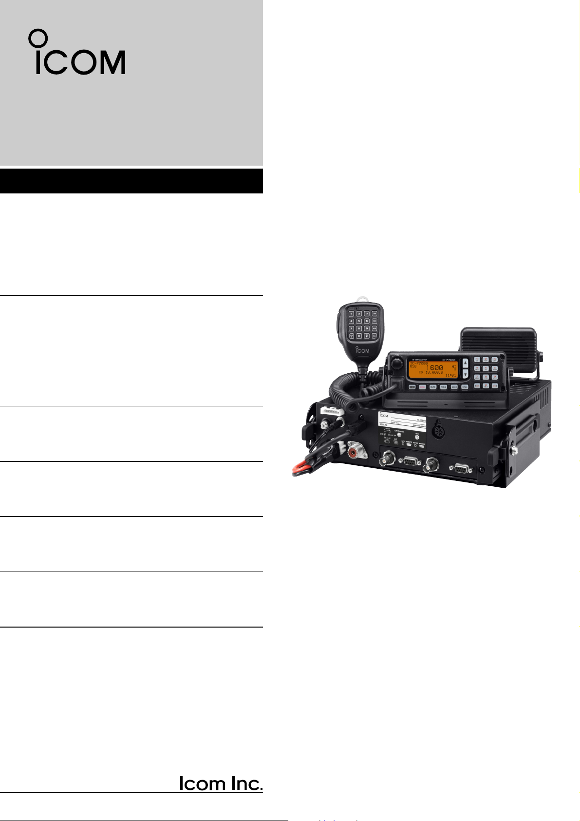
HF TRANSCEIVER
iF7000
INSTRUCTION MANUAL
Page 2

i
FOREWORD
Thank you for purchasing this Icom product. The ICF7000
HF TRANSCEIVER
is designed and built with
Icom’s superior technology and craftsmanship. With
proper care, this product should provide you with years
of trouble-free operation.
We want to take a couple of moments of your time to
thank you for making the IC-F7000 your radio of
choice, and hope you agree with Icom’s philosophy of
“technology first.” Many hours of research and development went into the design of your IC-F7000.
D
FEATURES
❍ ALE (Automatic Link Establishment)/Selcall
capability
❍ Digital Signal Processor (DSP) allows flex-
ible filter selection
❍ Full-dot matrix LCD for variety of informa-
tion indication
❍ PC connection capability for remote control
IMPORTANT
READ THIS INSTRUCTION MANUAL
CAREFULLY before attempting to operate the
transceiver.
SAVE THIS INSTRUCTION MANUAL. This
manual contains important safety and operating instructions for the IC-F7000.
EXPLICIT DEFINITIONS
R WARNING RF EXPOSURE! This device
emits Radio Frequency (RF) energy. Extreme caution
should be observed when operating this device. If you
have any questions regarding RF exposure and safety
standards please refer to the Federal Communications
Commission Office of Engineering and Technology’s
report on Evaluating Compliance with FCC Guidelines
for Human Radio Frequency Electromagnetic Fields
(OET Bulletin 65).
R WARNING HIGH VOLTAGE! NEVER at-
tach an antenna or internal antenna connector during
transmission. This may result in an electrical shock or
burn.
R NEVER apply AC to the [DC13.8V] jack on the
transceiver front panel. This could cause a fire or damage the transceiver.
R NEVER apply more than 16 V DC, such as a 24 V
battery, to the [DC13.8V] jack on the transceiver front
panel. This could cause a fire or damage the transceiver.
R NEVERlet metal, wire or other objects touch any
internal part or connectors on the front panel of the
transceiver. This may result in an electric shock.
R NEVER expose the transceiver to rain, snow or
any liquids.
AVOID using or placing the transceiver in areas with
temperatures below –10°C (+14°F) or above +60°C
(+140°F). Be aware that temperatures on a vehicle’s
dashboard can exceed 80°C (+176°F), resulting in permanent damage to the transceiver if left there for extended periods.
AVOID placing the transceiver in excessively dusty en-
vironments or in direct sunlight.
AVOID placing the transceiver against walls or putting
anything on top of the transceiver. This will obstruct
heat dissipation.
Place unit in a secure place to avoid inadvertent use
by children.
During mobile operation, DO NOT operate the trans-
ceiver without running the vehicle’s engine. When the
transceiver’s power is ON and your vehicle’s engine is
OFF, the vehicle’s battery will soon become exhausted.
Make sure the transceiver power is OFF before starting the vehicle. This will avoid possible damage to the
transceiver by ignition voltage spikes.
BE CAREFUL! The rear panel will become hot when
operating the transceiver continuously for long periods.
USE Icom microphones only (supplied or optional).
Other manufacturer’s microphones have different pin
assignments, and connection to the IC-F7000 may
damage the transceiver.
DO NOT use chemical agents such as benzine or al-
cohol when cleaning, as they can damage the transceiver surface.
PRECAUTION
WORD DEFINITION
RR
WARNING
Personal injury, fire hazard or electric
shock may occur.
CAUTION Equipment damage may occur.
NOTE
If disregarded, inconvenience only. No
risk or personal injury, fire or electric
shock.
Page 3
Icom, Icom Inc. and the are registered trademarks of
Icom Incorporated (Japan) in the United States, the United
Kingdom, Germany, France, Spain, Russia and/or other
countries.
ii
FOREWORD ……………………………………………i
IMPORTANT …………………………………………… i
EXPLICIT DEFINITIONS …………………………… i
PRECAUTION ………………………………………… i
TABLE OF CONTENTS …………………………… ii
1PANEL DESCRIPTION ………………………… 1–6
■ Front panel— Controller ………………………… 1
■ Front panel— Main unit ………………………… 3
■ Microphone (HM-155) ………………………… 4
■ LCD screen ……………………………………… 5
2 BASIC OPERATION ………………………… 7–11
■ Selecting a channel …………………………… 7
■ Scan function …………………………………… 8
■ Setting a frequency ……………………………… 9
■ Mode selection ………………………………… 10
■ Simple mode operation ……………………… 10
■ Split frequency operation ……………………… 11
3 RECEIVE AND TRANSMIT ………………… 12–18
■ Basic voice transmit/receive ………………… 12
■ Functions for transmit ………………………… 13
■ Functions for receive ………………………… 15
■ CW operation …………………………………… 18
■ FSK operation ………………………………… 18
4 SELCALL/ALE OPERATION ……………… 19–30
■ Selcall/ALE ……………………………………… 19
5 CHANNEL/ID PROGRAMMING …………… 31–35
■ Programming a channel ……………………… 31
■ Programming an ID …………………………… 33
6 SET MODE …………………………………… 36–53
■ Quick set mode ………………………………… 36
■ Initial set mode ………………………………… 40
■ CPU reset ……………………………………… 53
7 CONNECTION AND INSTALLATION …… 54–50
■ Supplied accessories ………………………… 54
■ Connections ……………………………………55
■ Ground connection …………………………… 56
■ Power source …………………………………… 56
■ Antenna ………………………………………… 57
■ Mounting ………………………………………… 58
■ Fuse replacement ……………………………… 60
■ Connector information ………………………… 61
8 SPECIFICATIONS ……………………………… 63
9 OPTIONS ………………………………………… 64
TABLE OF CONTENTS
1
2
3
4
5
6
7
8
9
PANEL DESCRIPTION
BASIC OPERATION
RECEIVE AND TRANSMIT
SELCALL /ALE OPERATION
CHANNEL/ID PROGRAMMING
SET MODE
CONNECTION AND INSTALLATION
SPECIFICATIONS
OPTIONS
Versions of the IC-F7000 which display
the “N33” symbol on the serial number
seal, comply with Standard Australia
Specification No. AS/NZS 4770: 2000.
Page 4
1
1
PANEL DESCRIPTION
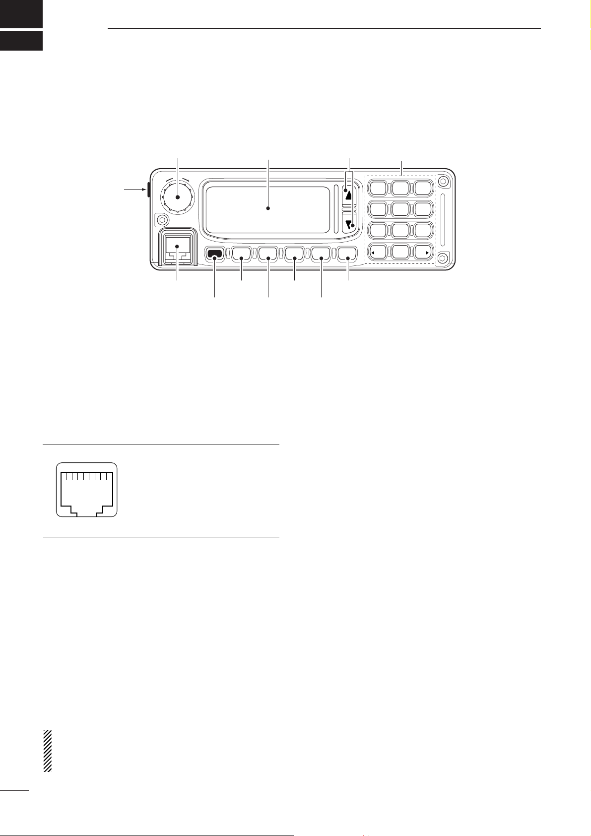
■ Front panel— Controller
q VOLUME [VOL] (p.12)
Adjusts the audio output level.
w SPEAKER JACK [EXT SP]
Connects the supplied external speaker, SP-25.
e MICROPHONE CONNECTOR [MIC]
Connects the microphone, supplied with the transceiver.
q +8 V DC output (Max. 10 mA)
w Channel up/down
e Mic backlight control line
r PTT
t GND (microphone ground)
y MIC (microphone input)
u GND
i Data IN
r POWER KEY [I/O]
➥ While transceiver’s power is OFF:
Push to turn power ON.
•Turn the DC power supply ON in advance.
➥ While transceiver’s power is ON:
❍ Push momentarily to enter the Quick set mode.
• Push again to exit the Quick set mode.
❍ Push for 1 sec. to turn power OFF.
t EMERGENCY KEY [EMG]
➥ Push to enter the RFDS channel group.
•Push again to return the normal operating mode.
➥ Push for 2 sec. to transmit the RFDS Call.
•1st registered channel is selected automatically when
display is indicated other than the RFDS channel group.
NOTE: The RFDS call is available for AUS version
only. This key is assigned as Emergency Selcall for
other versions. The operation of Emergency Selcall
is same as RFDS call.
y MUTE KEY [MUTE]
Push to select the mute types. Available types are
voice mute, signal level mute (level 1—100), call
mute or mute OFF.
•When select the mute type, transceiver emits different
confirmation beep for each type.
OFF—1 long beep,
Call mute—1 short beep,
Signal level mute—2 short beeps,
Voice mute—3 short beeps
u TUNER KEY [TUNE] (pgs.12, 14)
➥ Push for 1 sec. to start manual tune the optional
automatic antenna tuner.
•“Tuning” appears while tuning.
•When the tuner cannot tune the antenna, the tuning
circuit is bypassed automatically after 20 sec.
➥ Push momentarily to toggle the optional auto-
matic antenna tuner (AT-140 only) ON and OFF
(bypass).
i SCAN KEY [SCAN]
Push to start and stop the scanning.
o CALL KEY [CALL]
➥ Push to enter the Call menu.
• Push again to exit the Call menu.
➥ Push for 1 sec. to transmit the Call.
!0 UP/DOWN KEYS [∫∫]/[√√]
Selects the operating channel and the items of the
set mode, etc.
[VOL]
[EXT SP]
w
q!0
VOL
[MIC]
e
[I/O]
r
Function display Keypad
HF TRANSCEIVER
EMG
I/O
[EMG]
t
y
q
i
u
[MUTE]
[UP]/[DN]
iF7000
TUNE SCAN CALLMUTE
[TUNE]
i
o
[SCAN]
[CALL]
1QZ2
ABC3DEF
4
GHI5JKL6MNO
7
PRS8TUV9WXY
0
CLR
@?
OK
Page 5
2
1
PANEL DESCRIPTION
1
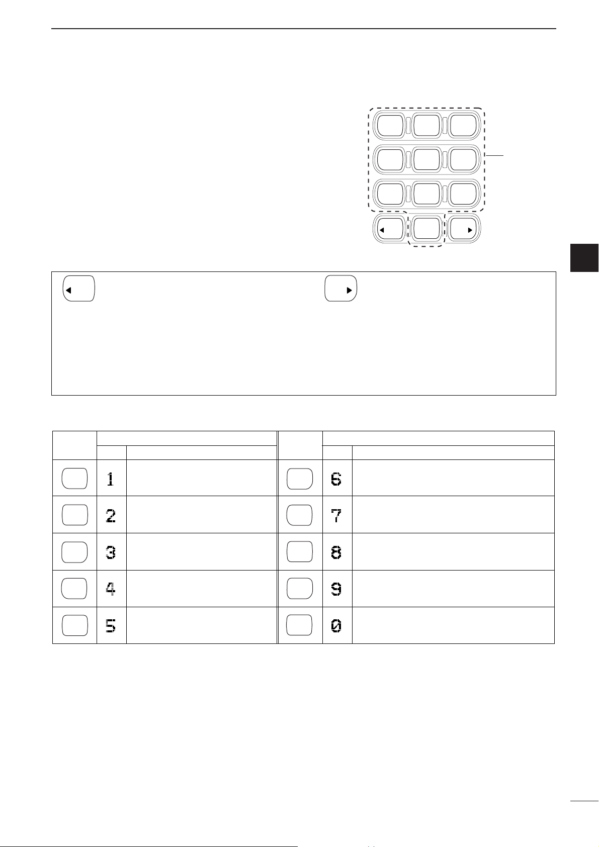
DD
Keypad
➥ Inputs numeral for the TEL number, ID number,
channel number input, etc.
➥ Inputs numeral and alphabet (some symbol) for
the message input of the Page call function or
channel comment input, etc.
1
QZ
2
ABC
3
DEF
4
GHI
5
JKL
6
MNO
7
PRS
8
TUV
9
WXY
CLR
0
@?
OK
10-key
[
ΩΩ
CLR]
➥ Push momentarily to move the cursor
backward.
➥ Push momentarily to decrease the set-
ting value for the set mode.
➥ Push momentarily to indicate receive
message when standby condition.
[OK ≈≈]
➥ Push to move the cursor forward.
➥ Push to increase the setting value for
the set mode.
➥ Push to indicate receive message when
standby condition.
➥ Push to fix input of channel comments.
OK
CLR
•Available characters
(space)
KEY
COMMENTSCH
INPUT INPUT
CH
KEY
COMMENTS
1 Q Z q z 6 M N O m n o
2 A B C a b c 7 P R S p r s
3 D E F d e f 8 T U V t u v
4 G H I g h i 9 W X Y w x y
5 J K L j k l 0 - / . ' ( ) * + < = > @
1
QZ
2
ABC
3
DEF
4
GHI
5
JKL
6
MNO
7
PRS
8
TUV
9
WXY
0
@?
Page 6
3
1
PANEL DESCRIPTION
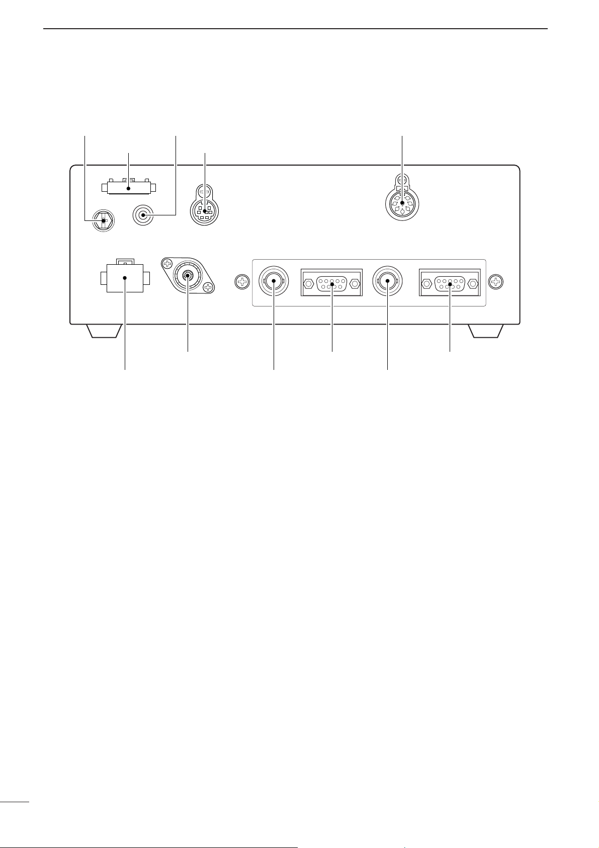
■ Front panel— Main unit
q DC POWER SOCKET
Accepts 13.8 V DC through the supplied DC power
cable.
w ANTENNA CONNECTOR
Connects a 50 Ω HF band antenna via a 50 Ω
matched coaxial cable with a PL-259 plug for both
transmit and receive operation.
e GPS CONNECTOR [GPS]
Input position and UTC data (NMEA0183 ver. 2.0 or
3.01 format), such as from a GPS receiver for setting your positioning and time data automatically.
r REMOTE CONNECTOR [REMOTE]
Connects to a PC via an RS-232C cable (D-sub 9pin) for remote control in the NMEA or RS-232C format.
t REFERENCE CONNECTOR [REF IN]
Connects to an external frequency oscillator for reference. Ask your technical dealer for details.
y MODEM CONNECTOR [AF/MOD]
Connects to an e-mail modem, NBDP (Narrow
Band Direct Printing) or FAX system.
u ACCESSORY CONNECTOR [ACC]
Connects a CW keyer or an FSK terminal unit, etc.
i CONTROLLER CONNECTOR [CONTROLLER]
Connects the supplied remote controller, RC-26.
o SPEAKER JACK [EXT SP]
Connects the supplied external speaker, SP-25.
!0 TUNER CONTROL SOCKET
Connects a control cable to an optional antenna
tuner.
A female connector kit is supplied for external antenna tuner connection.
!1
GROUND TERMINAL
IMPORTANT! Connects a ground.
GND EXT SP
!1
TUNER
!0
DC 13.8 V
q
o
w
i
ANT
CONTROLLER
REMOTE
r y
GPS
e t
ACC
u
REF IN
AF/MOD
Page 7
4
1
PANEL DESCRIPTION
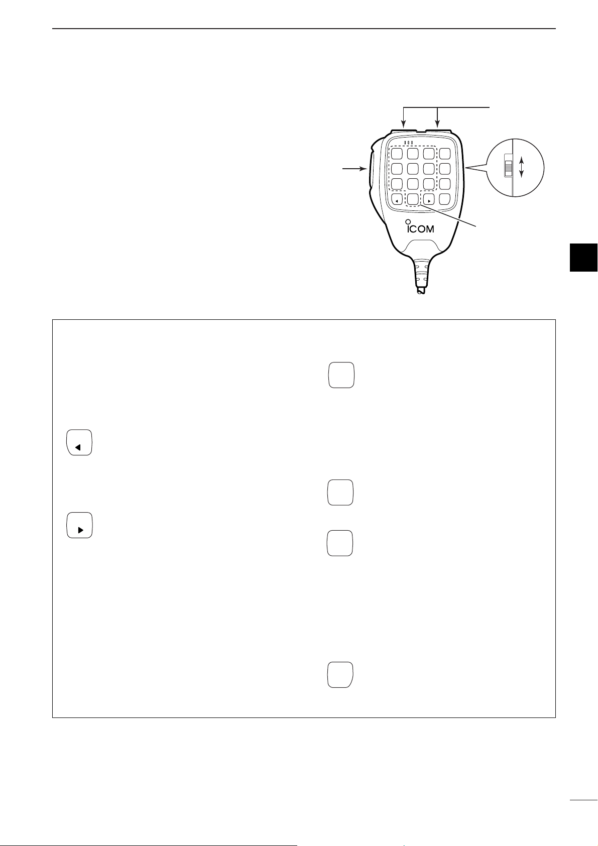
■ Microphone (HM-155)
q PTT SWITCH [PTT]
Push and hold to transmit; release to receive.
w UP/DOWN SWITCHES [
UUPP
]/[
DDNN
]
Push either switch to change the operating channel,
frequency, etc.
e UP/DOWN LOCK SWITCH
Slide to toggle [UP]/[DN] switches function ON and
OFF.
DD
Keypad
[
1100--kkeeyy
]
➥ Inputs numeral for the TEL number, ID number,
channel number input, etc.
➥ Inputs numeral and alphabet (some symbol) for
the message input of the Page call function or
channel comment input, etc.
• Available characters are shown at page 2.
[
ΩΩ
CLR]
➥ Push momentarily to move the cursor
backward.
➥ Push momentarily to decrease the set-
ting value for the set mode.
➥ Push momentarily to indicate receive
message when standby condition.
[OK ≈≈]
➥ Push to move the cursor forward.
➥ Push to increase the setting value for
the set mode.
➥ Push to indicate receive message when
standby condition.
➥ Push to fix input of channel comments.
[TUNE]
➥ Push for 1 sec. to start manual tune the
optional antenna tuner.
•“Tuning” appears while tuning.
•When the tuner cannot tune the antenna,
the tuning circuit is bypassed automatically
after 20 sec.
➥ Push momentarily to toggle the optional
automatic antenna tuner (AT-140 only)
ON and OFF (bypass).
[SCAN]
➥ Push to start and stop the scanning.
[MUTE]
➥ Push to select the mute types. Available
types are voice mute, signal level mute
(level 1—100), call mute or mute OFF.
•When select the mute type, transceiver
emits different conformation beep for each
type.
OFF—1 long beep,
Call mute—1 short beep,
Signal level mute—2 short beeps,
Voice mute—3 short beeps
[CALL]
➥ Push to enter the Call menu.
• Push again to exit the Call menu.
➥ Push for 1 sec. to transmit the Call.
CALL
MUTE
SCAN
TUNE
OK
CLR
21 3
54 6
TUNE
SCAN
mic
87 9
MUTE
0
CALL
CLR OK
q
[PTT]
ON
OFF
e
[LOCK]
w
[UP]/[DN]
10-key
1
Page 8

5
1
PANEL DESCRIPTION
DD
Channel indication
q COMMENT INDICATOR
➥ Shows the programmed channel comment or
comment with position data when connected GPS
receiver.
➥ Shows the condition while scanning/tuning.
•“Scanning” appears when the scan function is ac-
tivated.
•“Tuning” appears while tuning, if an optional exter-
nal antenna tuner is connected. (pgs. 55, 57)
•“Tuned” appears after the tuning is completed.
w
OPERATING MODE INDICATOR
Shows the selected operating mode.
•“USB,” “LSB,” “AM,” “CW,” “FSK,” “AFSK,” “ALE-U,”
“ALE-L” or “EMAIL” appears depending on operating
mode and setting. (Selectable mode is USB only for AUS
version.)
e TRANSMIT/RECEIVE INDICATOR
➥ “RX” appears when signals are received or the
squelch is open.
➥ “TX” appears during transmit.
r FREQUENCY INDICATOR
Shows the transmit/receive frequency of the channel. Receive frequency is displayed during reception, transmit frequency is displayed during trans-
mission. By setting the Initial set mode, both
receive/transmit frequencies can be displayed at
same time. (pgs. 14, 52)
t LQA LEVEL INDICATOR
Shows the LQA level (0–30) for displayed channel
while “ALE-U” or “ALE-L” mode is selected.
•“--”means measurement data is not available.
y S-METER INDICATOR
Shows the receiving signal strength during receive.
u SIMPLE MODE INDICATOR
“-” appears while in simple mode operation.
•While in simple mode operation, Quick set mode, Initial
set mode or etc. cannot be edited.
i TRANSMIT POWER INDICATOR
Shows the selected transmit output power.
•“HI,” “MID,” “LO” appears when the transmit power is
set to high power, middle power, low power respectively.
o MUTE INDICATOR
➥ “V” appears when the voice mute is selected.
➥ “L” appears when the Signal level mute is se-
lected.
➥ “S” appears when the call mute is selected.
!0 CHANNEL NUMBER INDICATOR
➥ Shows the selected channel number.
➥ Channel number blinks while stopping the scan.
!1 TIME INDICATOR
Shows time data.
■ LCD screen
q
w
e
r
t
ALE-CHANNEL-1
USB-A
RX-12.163.5
LQA:20 ========-------- 12:34
-
HI
S
y
u
i
o
!0
!1
Page 9

6
1
PANEL DESCRIPTION
1
DD
Frequency indication
q
OPERATING MODE INDICATOR
Shows the selected operating mode.
•“USB,” “LSB,” “AM,” “CW,” “FSK,” “AFSK,” “ALE-U,”
“ALE-L” or “EMAIL” appears depending on operating
mode and setting. (Selectable mode is USB only for AUS
version.)
w TRANSMIT/RECEIVE INDICATOR
➥ “RX” appears when signals are received or the
squelch is open.
➥ “TX” appears during transmit when the split func-
tion is OFF.
e TRANSMIT/RECEIVE FREQUENCY INDICATOR
Shows the transmit/receive frequency of the channel. Receive frequency is displayed during reception, transmit frequency is displayed during transmission when the split function is OFF.
r TRANSMIT INDICATOR
“TX” appears during transmit when the split function
is ON.
t TRANSMIT FREQUENCY INDICATOR
Shows the transmit frequency when the split function is ON.
y PREAMPLIFIER INDICATOR
“P.AMP” appears when the Preamp function is ON.
u S-METER INDICATOR
Shows the receiving signal strength during receive.
i TRANSMIT POWER INDICATOR
Shows the selected transmit output power.
•“HI,” “MID,” “LO” appears when the transmit power is
set to high power, middle power, low power respectively.
o MUTE INDICATOR
➥ “V” appears when the voice mute is selected.
➥ “L” appears when the signal level mute is se-
lected.
➥ “S” appears when the call mute is selected.
!0 TIME INDICATOR
Shows time data.
q
w
e
r
t
y
ALE-U
RX
TX-12.163.5
P.AMP ========-------- 12:34
HI
S
u
i
o
!0
Page 10
2
7
BASIC OPERATION
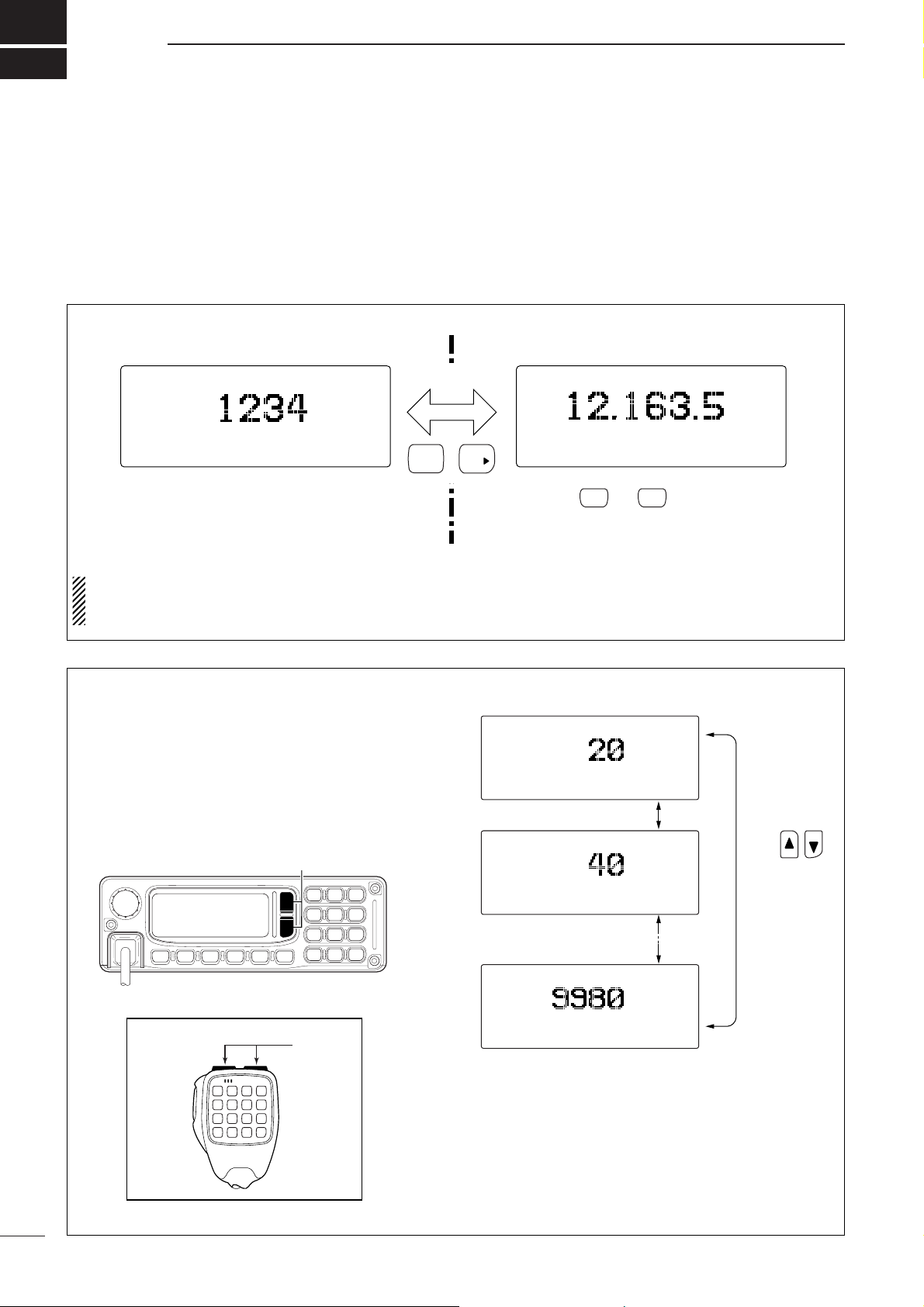
■ Selecting a channel
The transceiver has 400 regular channels and 100
ALE channels. However, the number of channels can
be restricted in programming depending on your
needs. 2 ways of channel selections are available to
suit your operating style.
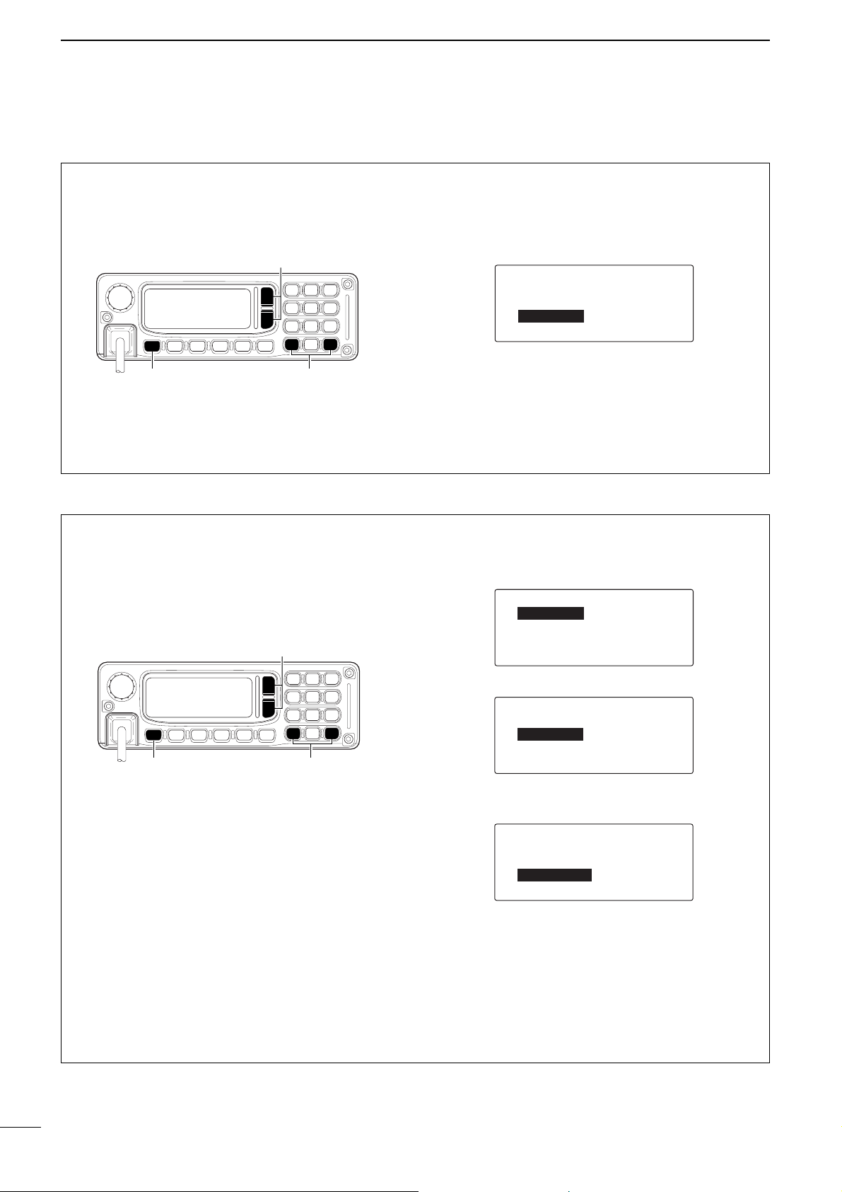
D Using up/down keys
When the display selection is selected the channel in-
dication (see above), push [√√]/[∫∫] on the FRONT
panel or [UP]/[DN] on the microphone to select the
desired channel.
This way is convenient when changing a small number of channels.
Channel 20
Channel 40
Channel 9980
Push
switch to select
a channel
SELCALL
LSB HI
--0:55
RX 9.900.0
RADTEL
USB HI
--0:55
RX 9.999.9
RADTEL
USB HI
--0:55
RX 0.499.9
[∫]/[√]
[UP]/[DN]
Microphone
or
DD
Display selection channel/VFO
NOTE: Channel comment (alphanumeric) disap-
pears during Frequency indication. Also Entering
the Initial set mode is restricted.
ALE-CHANNEL-1
USB-A
RX-12.163.5
HI
12:34
@?
0
VFO (FREQUENCY) indicationCHANNEL indication
USB
RX
TX-12.163.5
+
OK
HI
S
12:34
When or is pushed, the
frequency indication is canceled, and
returns to the channel indication
automatically.
SCAN CALL
Page 11
8
2
BASIC OPERATION
2
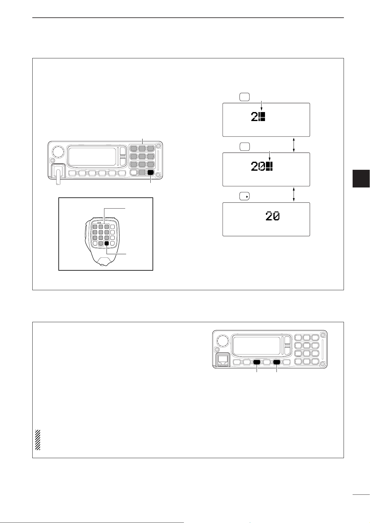
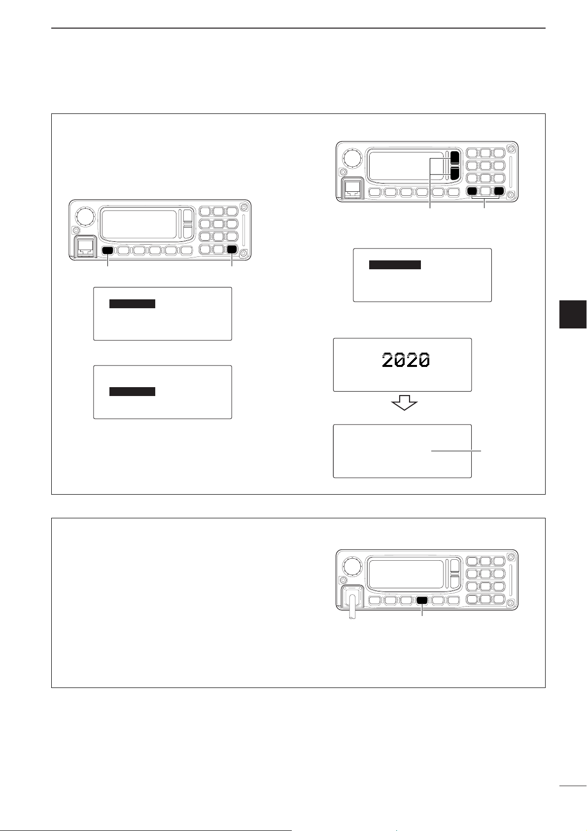
D Using the keypad
Enter the number of the desired channel number
using the keypad (0 to 9), then push [OK ≈≈] on the
FRONT panel or microphone.
This way is convenient for remembering the usage
and stored channel number, or when changing large a
number of channels.
•Pushing [
ΩΩ
CLR] clears input digits and retrieves the chan-
nel.
[EXAMPLE]: Selecting channel 20
Push
Push
Push
Blinks
2
ABC
0
@?
OK
RADTEL
USB HI
--0:55
RX 0.499.9
SELCALL
LSB HI
--0:55
RX 8.800.0
SELCALL
LSB HI
--0:55
RX 8.800.0
Blinks
Microphone
[OK ≈]
[10-key]
or
[OK ≈]
[10-key]
Scan function repeatedly scans programmed channels. This function is convenient to wait for calls on
multiple channels.
q Push [MUTE] several times to select the voice
mute.
• The mute type indicator “V” appears.
w Push [SCAN] to start the scan.
• The “Scanning” indicator appears.
e When a signal is received, channel scan pauses
on that channel.
r Push any key to cancel the scan.
NOTE: The scan resume condition (the action after
signal receiving) can be selected as ‘SCAN RE-
SUME’ in the Initial set mode. (p. 45)
[MUTE][SCAN]
■ Scan function
Page 12
9
2
BASIC OPERATION
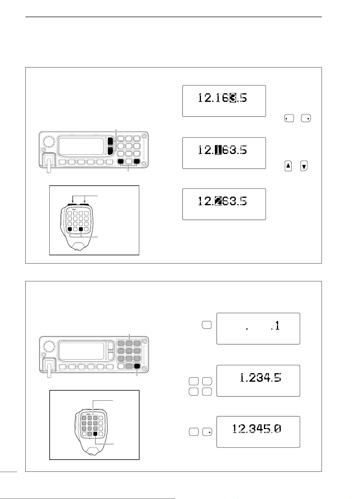
D Using up/down keys
When the display selection is selected the frequency
indication (p. 7), push [
ΩΩ
CLR] or [OK ≈≈] to move the
cursor to desired tuning steps, then push [√√]/[∫∫] on
the FRONT panel or [UP]/[DN] on the microphone to
change the frequency.
Push
key to change the
frequency in selected
tuning steps.
Push
key to change the
tuning steps.
or
or
USB HI
RX
P.AMP --0:55
USB HI
RX
P.AMP --0:55
USB HI
RX
P.AMP --0:55
CLR OK
[∫]/[√]
Microphone
or
[Ω CLR]/[OK ≈]
[UP]/[DN]
[Ω CLR]/[OK ≈]
D Using the keypad
Enter the desired frequency using the keypad (0 to 9),
then push [OK ≈≈].
• Pushing [
ΩΩ
CLR] clears input digits and retrieves the chan-
nel.
Push
Push
Push
USB HI
RX
P.AMP --0:55
USB HI
RX
P.AMP --0:55
USB HI
RX
P.AMP --0:55
[EXAMPLE]: Entering 12.3450 MHz
1
QZ
2
ABC3DEF
4
GHI5JKL
0
@?
OK
Microphone
[OK ≈]
[10-key]
or
[OK ≈]
[10-key]
■ Setting a frequency
Page 13
10
2
BASIC OPERATION
2
The following modes are available in the IC-F7000:
USB, LSB, AM, CW, FSK, AFSK, ALE-U, ALE-L and
EMAIL.
q Push [I/O] to enter the Quick set mode.
w Push [√√]/[∫∫] several times to select ‘MODE,’ then
push [
ΩΩ
CLR] or [OK ≈≈] to select the desired
mode.
• The selected mode is indicated in the function display.
NOTE: The selected mode can be used for tempo-
rary operation only. Once changing the channel or
turning OFF the transceiver to return the original
operating mode
NOTE: If you want to change the operating mode
on the channel permanently, refer to channel programming. (pgs. 31, 32)
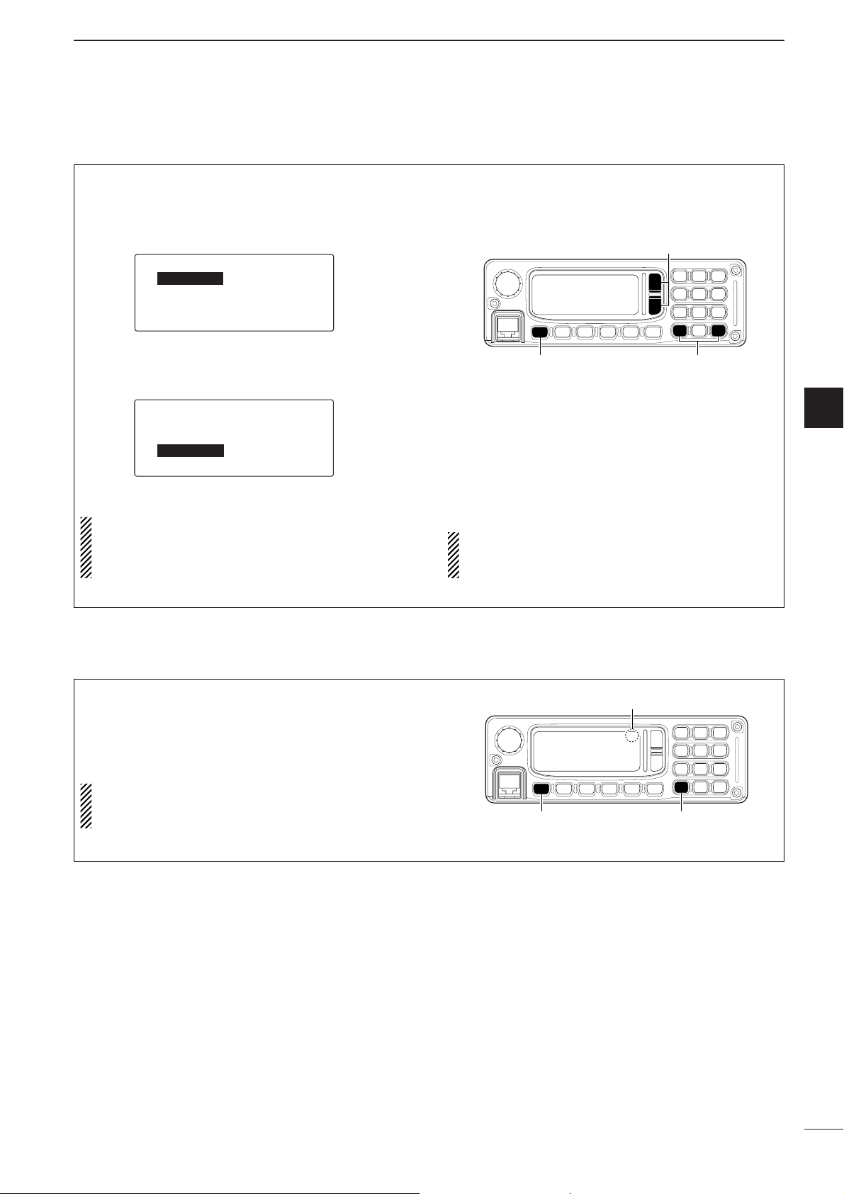
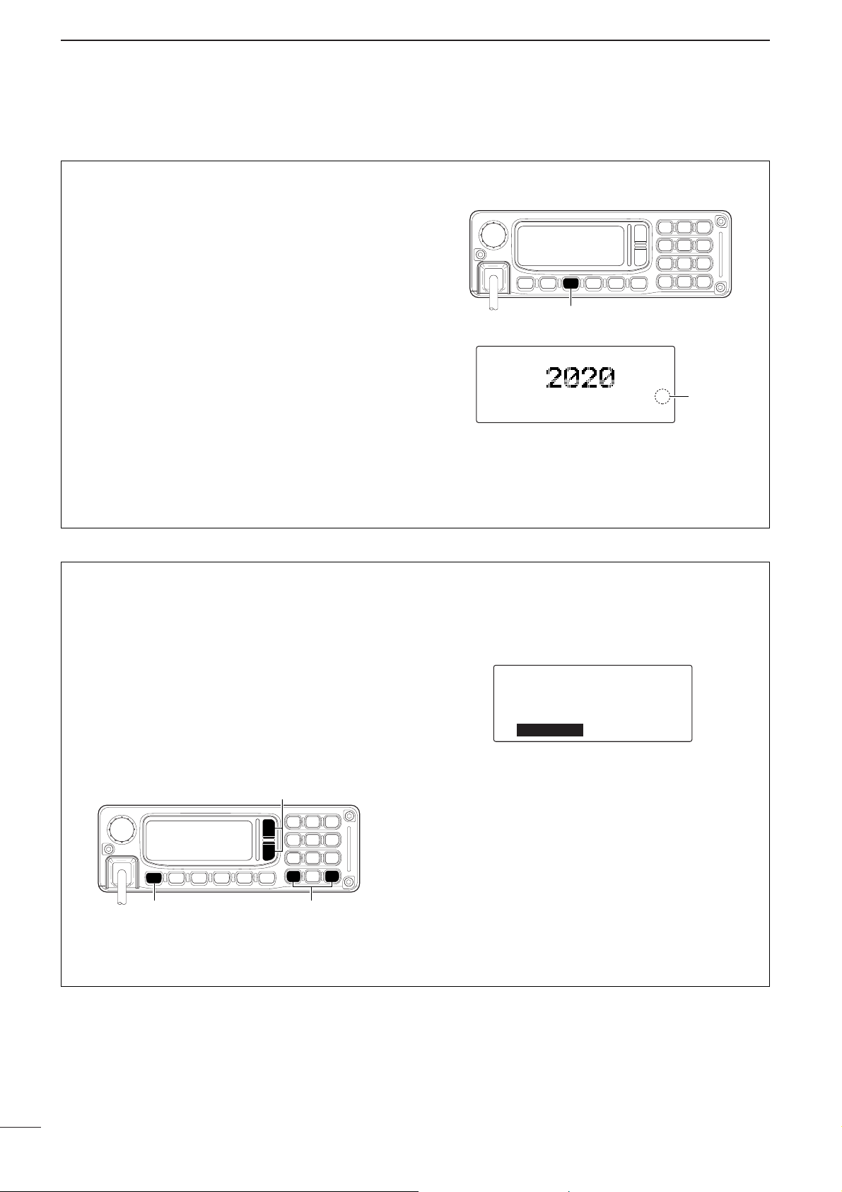
■ Mode selection
While pushing and holding [
ΩΩ
CLR], turn power ON
to turn the Simple mode operation ON.
•“-” appears upper-right corner on the display.
• Repeat above procedure to turn the Simple mode operation OFF.
NOTE: While in simple operating mode, Quick set
mode, Initial set mode, Frequency indication are re-
stricted.
[I/O] [Ω CLR]
Simple mode indication
-
■ Simple mode operation
Q-SET-MODE
--LCD-CONT--ç-7-å
--DIMMER----6>0
--TX-PWR----HI
è-RF-GAIN---9
é-SQL-LV----30
--FILTER----WIDE
--RIT-------0
--MODE------ç-USB----å
--BEEP-LV---5
[∫]/[√]
[I/O] [Ω CLR]/[OK ≈]
Page 14
11
2
BASIC OPERATION
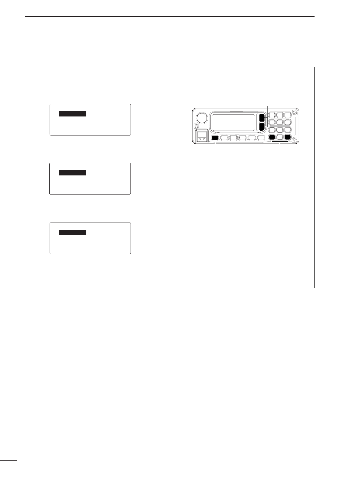
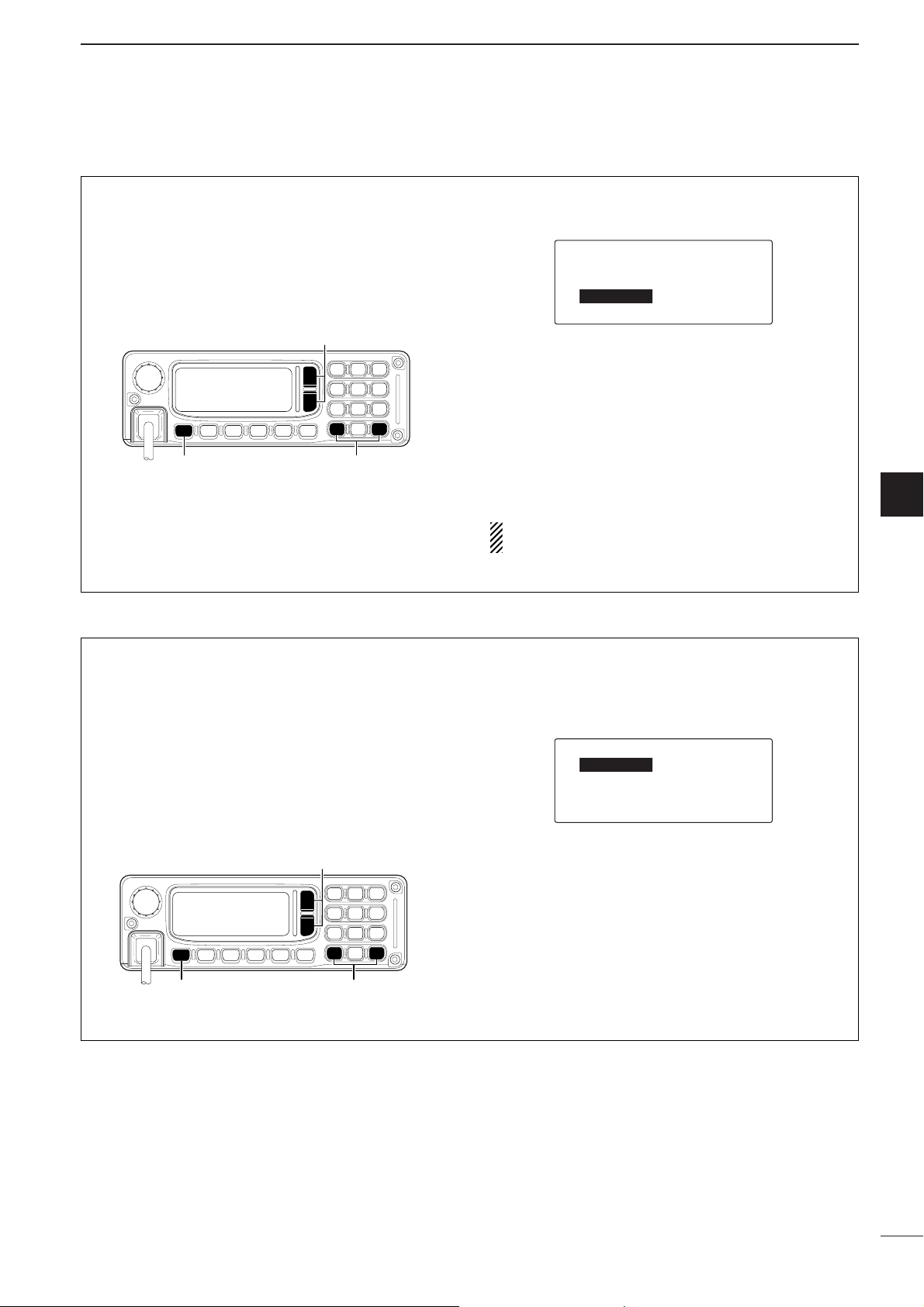
Split frequency operation allows you to transmit and
receive on two different frequencies.
q While in Frequency indication (p. 7), push [I/O] to
enter the Quick set mode.
w Push [√√]/[∫∫] several times to select ‘SPLIT,’ then
push [
ΩΩ
CLR] or [OK ≈≈] to select the split function
ON.
e Push [OK ≈≈] to select ‘DELTA,’ then push [OK ≈≈]
several times to move the cursor to desired tuning
steps, then
push [
√√
]/[∫∫] to change the frequency.
• After exiting the Quick set mode, the TX frequency is indi-
cated in the function display.
[I/O] [Ω CLR]/[OK ≈]
[∫]/[√]
é-RIT-------0
--SPLIT-----ç-DELTA-å
------------0.000.0
--BEEP-LV---5
é-RIT-------0
--SPLIT-----ç-ON-å
--BEEP-LV---5
Q-SET-MODE(VFO)
--MODE------ç-USB----å
è-RF-GAIN---9
--SQL-LV----30
--PRE-AMP---ON
■ Split frequency operation
Page 15
3
12
RECEIVE AND TRANSMIT
2
3
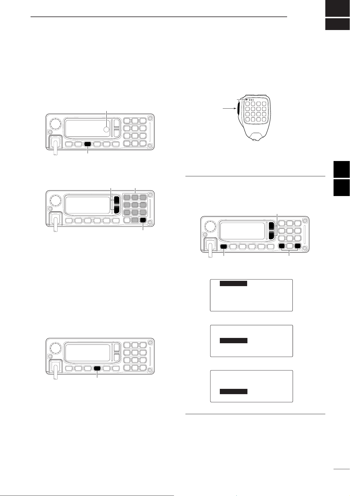
■ Basic voice transmit/receive
q Check the following in advance.
➥ Microphone is connected.
➥ No mute indication “S,” “L” or “V.”
•If one of “S,” “L” or “V” appears, push [MUTE] sev-
eral times to turn the mute OFF.
w
Selects the desired channel to be received with the
[√√]/[∫∫] or 10-key pad.
•
The S-meter shows signal strength when signal is received.
e Adjust [VOL] to the desired audio level when re-
ceiving a signal.
• If no audio appears, verify ‘SP OUT’ in the Quick set
mode is set to ‘ON.’ (see right)
• If the bass or treble of the receive audio is too strong,
select ‘RIT’ in the Quick set mode and adjust to obtain
clear audio. (see right)
• If Audio is distorted, select ‘MODE’ in the Quick set
mode and set the desired operating mode. (See right)
r Push [TUNE] to tune the antenna tuner ON, if con-
nected.
•“Tuning” indicator appears during the first tun-
ing on a channel.
t To transmit on the channel, push and hold [PTT] on
the microphone, and speak into the microphone at
a normal voice level.
• The RF meter shows the output power according to your
voice level.
y Release [PTT] to return to receive.
• Entering the Quick set Mode
q While transceiver’s power is ON, push [I/O] mo-
mentarily to enter the Quick set mode, then push
[√√] or [∫∫] to select the item and set the following.
‘SP OUT’
‘RIT’
‘MODE’
w Push [I/O] to exit the Quick set mode.
é-SQL-LV----30
--FILTER----WIDE
--RIT-------0
--MODE------ç-USB----å
--BEEP-LV---5
é-SQL-LV----30
--FILTER----WIDE
--RIT-------ç-0-å
--MODE------USB
--BEEP-LV---5
é-SP-OUT----ç-ON-å
--AGC-------ON
è-NB-LEVEL--9
--MIC-BL----6
--NB--------HI
[I/O] [Ω CLR]/[OK ≈]
[∫]/[√]
[PTT]
Microphone
[TUNE]
[OK ≈]
[10-key][∫]/[√]
[MUTE]
Mute indication
S
Page 16
■ Functions for transmit
ï Transmit power selection
The transceiver has 3 selectable power output levels.
High power allows longer distance communications
and low power reduces power consumption.
q Push [I/O] to enter the Quick set mode while trans-
ceiver’s power is ON.
w Push [∫∫] or [√√] to select ‘TX PWR.’
e Push [
ΩΩ
CLR] or [OK ≈≈] to select the desired out-
put power.
• Output power is selectable in 3 steps (LOW, MID and
HI).
r Push [I/O] to exit the Quick set mode and return to
the normal operating mode.
Q-SET-MODE
--LCD-CONT--ç-6-å
è-RF-GAIN---9
--DIMMER----6
--TX-PWR----HI
[I/O] [Ω CLR]/[OK ≈]
[∫]/[√]
ï Microphone compressor
IC-F7000 has a built-in, low distortion Mic compressor circuit. This circuit increases your average talk
power in SSB mode and is especially useful when the
receiving station is having difficulty copying your signal.
q While pushing and holding [OK ≈≈], turn power ON
to enter the Initial set mode.
w Push [√√] to select ‘GENERAL,’ then push [OK ≈≈].
e Push [√√] to select ‘COMP,’ then push [
ΩΩ
CLR] or
[OK≈≈] to turn the mic compressor ON.
r Turn power OFF and ON, then select USB or LSB
mode.
t Push and hold [PTT] on the microphone, and
speak into the microphone at a normal voice level.
GENERAL----
--DISP-TYPE--RX-TX
è-CLOCK------12:00
--COMMENT----ON
--COMP-------ç-ON-å
é-SELCALL----
--ALE--------
è-SCAN-------
--GENERAL----å
--I/O--------
SET-MODE
--CH-LIST----å
è-SCAN-------
--ID-LIST----
--I/O--------
[I/O] [Ω CLR]/[OK ≈]
[∫]/[√]
13
3
RECEIVE AND TRANSMIT
Page 17
14
3
RECEIVE AND TRANSMIT
3
ï Transmit frequency indication
Both receive/transmit frequencies can be displayed at
same time.
q While pushing and holding [OK ≈≈], turn power ON
to enter the Initial set mode.
w Push [√√] to select ‘GENERAL,’ then push [OK ≈≈].
e Push [√√] to select ‘DISP TYPE,’ then push
[ΩΩCLR] or [OK≈≈] to select ‘RX-TX.’
r Turn power OFF and ON.
SELCALL
USB-A
12:34
RX--3.200.0
HI
SELCALL
USB-A
12:34
RX--3.200.0
TX--3.200.0
2020-ch HI
TX frequency
indication
• Channel indication
• Frequency indication
GENERAL----
--DISP-TYPE--ç-RX-TX-å
è-CLOCK------12:00
--COMMENT----ON
--COMP-------OFF
[Ω CLR]/[OK ≈][∫]/[√]
é-SELCALL----
--ALE--------
è-SCAN-------
--GENERAL----å
--I/O--------
SET-MODE
--CH-LIST----å
è-SCAN-------
--ID-LIST----
--I/O--------
[I/O] [OK ≈]
■ Functions for transmit (Continued)
DD
Tuner through function
In the combination with IC F7000 and optional AT140, the tuner through function can be used.
By bypassing the tuner unit, the receiver gain in particular frequency band may be improved depending
on your antenna element length.
➥ While “TUNE” is displayed, push [TUNE] to tuner
through function ON.
•“TUNE“ disappears.
• Push [TUNE] again to reset the tuner.
[TUNE]
Page 18
15
3
RECEIVE AND TRANSMIT
■ Functions for receive
DD
RF gain setting
The receiver gain can be reduced with the RF gain
setting. This may help to remove undesired weak signals while monitoring strong signals.
Usually, the AGC function reduces the RF gain according to the receive signal strength and these weak
signals are removed. However, during no signal reception, these weak signals may not be heard.
In such cases, the RF gain may be useful for setting a
minimum level at which to hear signals.
q Push [I/O] to enter the Quick set mode while trans-
ceiver’s power is ON.
w Push [∫∫] or [√√] to select ‘RF GAIN.’
e Push [
ΩΩ
CLR] or [OK ≈≈] to set the desired mini-
mum cutting level.
•
“0” (low sensitivity) to “9” (max. sensitivity) are available.
r Push [I/O] to exit the Quick set mode and return to
the normal operating mode.
Q-SET-MODE
--LCD-CONT--6
è-RF-GAIN---ç-9-å
--DIMMER----6>0
--TX-PWR----HI
[I/O] [Ω CLR]/[OK ≈]
[∫]/[√]
DD
Squelch function
The squelch function detects signals with voice components and squelches (mutes) unwanted signals
such as unmodulated beat signals. This provides
quiet stand-by.
When you need to receive weak signals, the squelch
should be turned OFF.
➥ Push [MUTE] several times to select a mute type.
Available types are voice mute, signal level mute
(level 1—100), call mute or mute OFF.
•When select the mute type, transceiver emits different
confirmation beep for each type.
OFF—1 long beep,
Call mute—1 short beep,
Signal level mute—2 short beeps,
Voice mute—3 short beeps
• Mute indication, “S,” “L,” “V” appears when the squelch
function is turned ON.
SELCALL
USB-A
12:34
RX--3.200.0
HI
S
Mute
indication
[MUTE]
Page 19
3
16
RECEIVE AND TRANSMIT
3
ï Noise blanker
The noise blanker reduces pulse-type noise such as
that generated by automobile ignition systems.
The noise blanker may distort reception of strong signals. In such cases, the noise blanker should be
turned OFF.
q Push [I/O] to enter the Quick set mode while trans-
ceiver’s power is ON.
w Push [∫∫] or [√√] to select ‘NB.’
e Push [
ΩΩ
CLR] or [OK ≈≈] to turn the noise blanker
ON.
r Push [∫∫] or [√√] to select ‘NB LEVEL.’
t Push [
ΩΩ
CLR] or [OK ≈≈] to adjust the noise
blanker level.
y Push [I/O] to exit the Quick set mode and return to
the normal operating mode.
When using the noise blanker, received signals
may be distorted if they are excessively strong.
DD
AGC OFF function
The receive gain is automatically adjusted according
to received signal strength with the AGC (Automatic
Gain Control) function to prevent distortion from
strong signals and to obtain a constant output level.
When receiving weak signals with adjacent strong
signals or noise, the AGC function may reduce the
sensitivity. In this situation, the AGC function should
be deactivated.
q Push [I/O] to enter the Quick set mode while trans-
ceiver’s power is ON.
w Push [∫∫] or [√√] to select ‘AGC.’
e Push [
ΩΩ
CLR] or [OK ≈≈] to turn the AGC ON.
r Push [I/O] to exit the Quick set mode and return to
the normal operating mode.
é-SP-OUT----ON
--AGC-------ç-ON-å
--MIC-BL----OFF
--NB--------ON
è-NB-LEVEL--5
[I/O] [Ω CLR]/[OK ≈]
[∫]/[√]
■ Functions for receive (Continued)
[∫]/[√]
[I/O] [Ω CLR]/[OK ≈]
é-SP-OUT----ON
--AGC-------ON
--MIC-BL----OFF
--NB--------ç-ON-å
è-NB-LEVEL--5
Page 20
ï Preamp
The preamp amplifies received signals in the front
end circuit to improve the S/N ratio and sensitivity.
Turn this function ON when receiving weak signals.
• Channel indication (p. 7)
q While pushing and holding [OK ≈≈], turn power ON
to enter the Initial set mode.
w Push [√√] to select ‘GENERAL,’ then push [OK ≈≈].
e Push [√√] to select ‘PRE AMP,’ then push [
ΩΩ
CLR]
or [OK≈≈] to turn the preamp function ON.
r Turn power OFF and ON.
• Frequency indication (p. 7)
q Push [I/O] to enter the Quick set mode while trans-
ceiver’s power is ON.
w Push [√√] to select ‘PRE AMP,’ then push [
ΩΩ
CLR]
or [OK≈≈] to turn the preamp function ON.
e Push [I/O] to exit the Quick set mode and return to
the normal operating mode.
Q-SET-MODE(VFO)
--MODE------USB
è-RF-GAIN---9
--SQL-LV----30
--PRE-AMP---ç-ON-å
Q-SET-MODE(VFO)
--MODE------ç-USB----å
è-RF-GAIN---9
--SQL-LV----30
--PRE-AMP---ON
[I/O] [Ω CLR]/[OK ≈]
[∫]/[√]
é-PASSWORD---LOCK
--PRE-AMP----ç-ON-å
è-CLOCK------12:00
--VOL-MIN----0
--COMP-------ç-ON-å
é-SELCALL----
--ALE--------
è-SCAN-------
--GENERAL----å
--I/O--------
SET-MODE
--CH-LIST----å
è-SCAN-------
--ID-LIST----
--I/O--------
■ Functions for receive (Continued)
17
3
RECEIVE AND TRANSMIT
ï RIT function
The RIT (Receive Incremental Tuning) function compensates for off-frequencies of communicating stations. The function shifts the receive frequency up to
±150 Hz without moving the transmit frequency.
q Push [I/O] to enter the Quick set mode while trans-
ceiver’s power is ON.
w Push [∫∫] or [√√] to select ‘RIT.’
e Push [
ΩΩ
CLR] or [OK ≈≈] to tune the frequency.
• The transmit frequencies are not shifted.
r Push [I/O] to exit the Quick set mode and return to
the normal operating mode.
When cancelling the RIT function, tune the ‘RIT’ in
the Quick set mode to ‘0.’
[∫]/[√]
[I/O] [Ω CLR]/[OK ≈]
é-SQL-LV----30
--FILTER----WIDE
--RIT-------ç-0-å
--MODE------USB
--BEEP-LV---5
Page 21
18
3
RECEIVE AND TRANSMIT
3
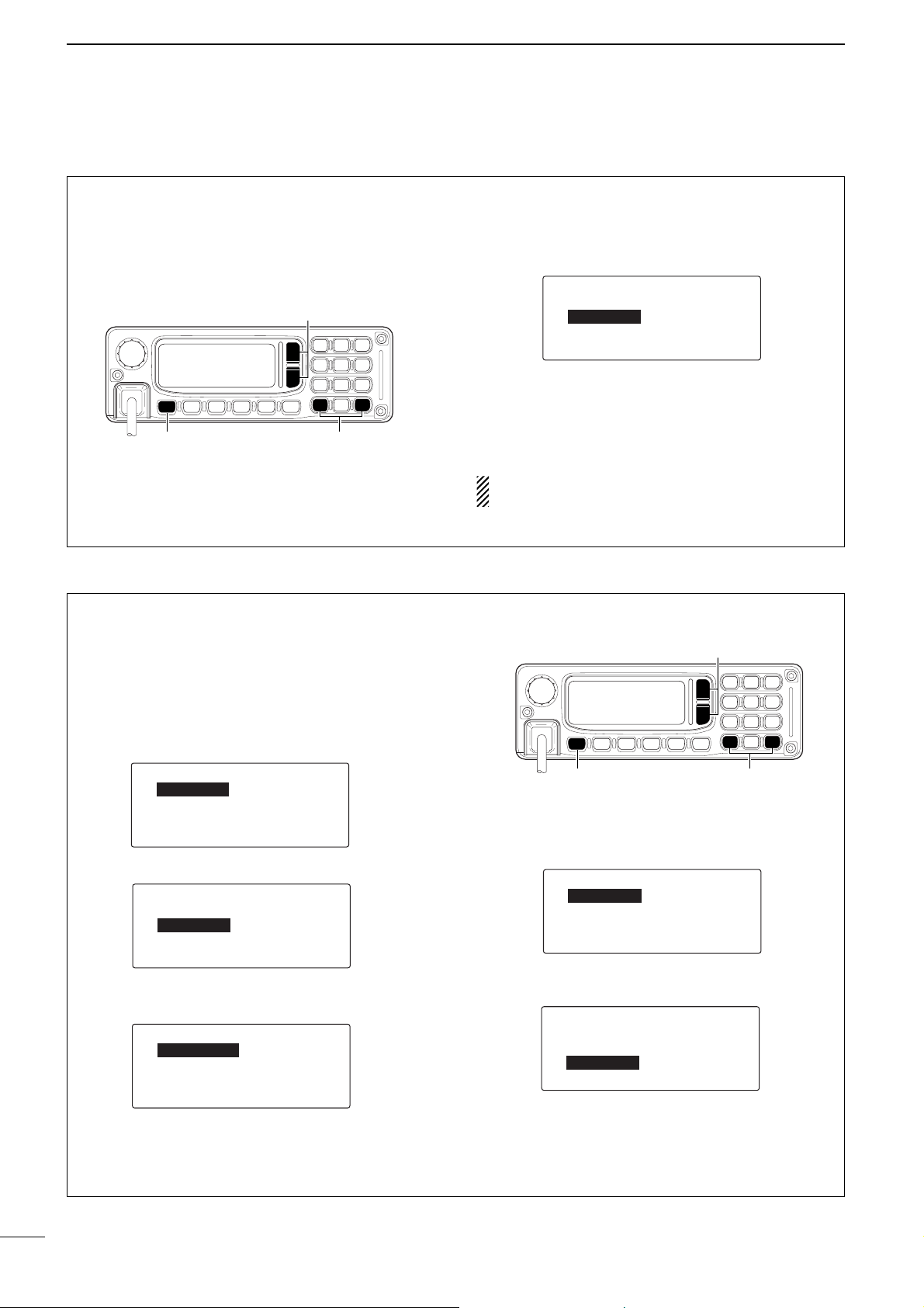
The transceiver has the following CW keying features
selectable in set mode as described on p. 43.
➥ Full break-in
(receiving is possible while transmitting)
➥ Semi break-in (automatic transmission with keying)
➥ OFF (manual transmission with microphone’s [PTT], or
grounding the SEND line of [ACC] connector is
necessary before keying)
q Connect a CW keyer or an external electronic
keyer to the [ACC] socket as shown at right.
w Select the desired channel to operate CW mode.
e If the selected channel is not in CW mode, set to
select ‘CW.’ (p.18)
r Operate the CW keyer to transmit a CW signal.
CW key connection
1
2
3
4
5
6
7
8
To pin 2
PTT*
*manual transmission switch for break-in
OFF setting.
To pin 1
To pin 3
■ CW operation
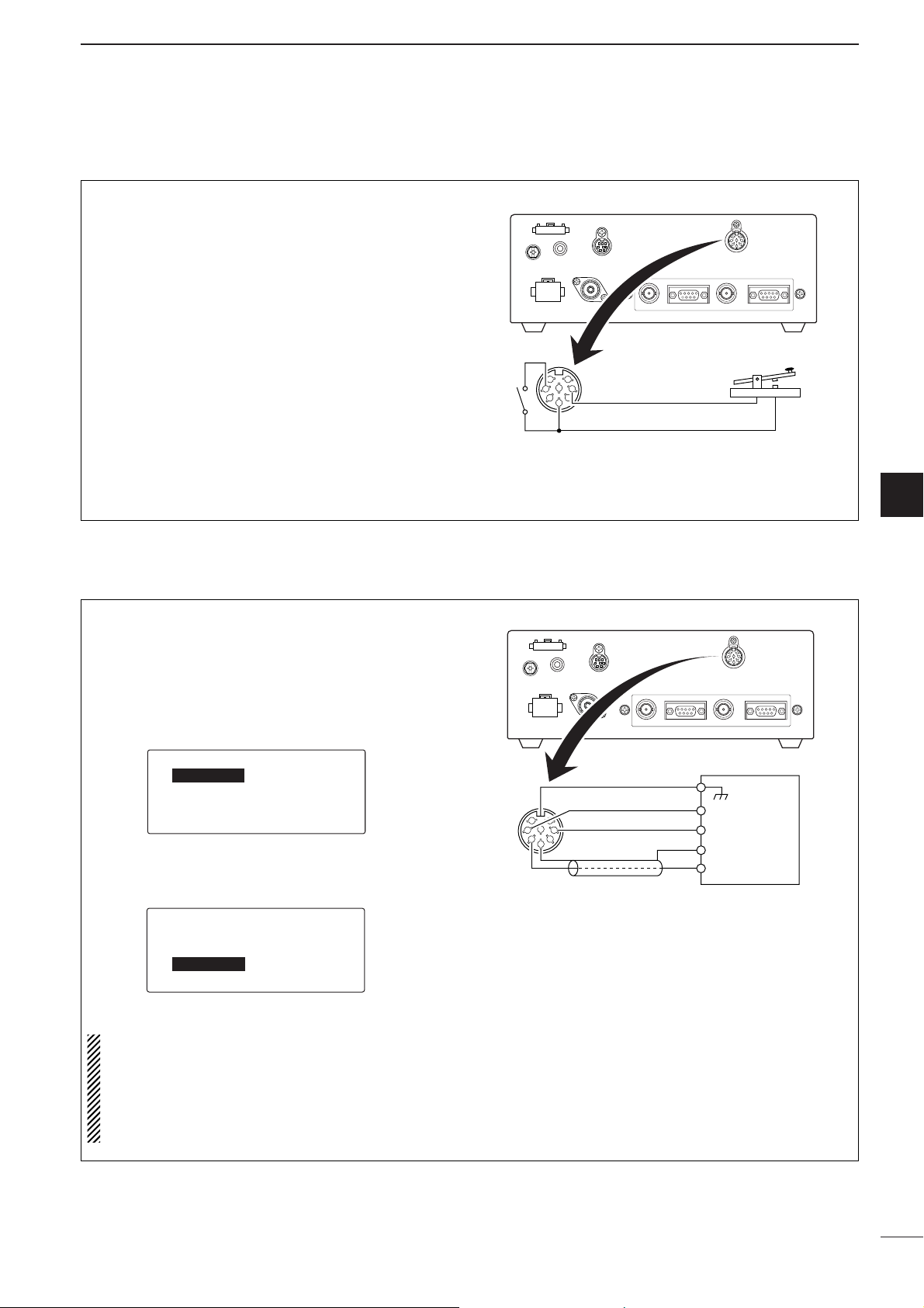
The transceiver has FSK and AFSK modes for FSK
operation— use FSK when using the built-in oscillator; use AFSK when using an AFSK terminal unit.
q Connect an FSK terminal unit to the [ACC] socket
as shown at right.
w Select the desired channel to operate FSK mode.
e Push [I/O] to enter the Quick set mode.
r Push [√√]/[∫∫] several times to select ‘MODE,’ then
push [
ΩΩ
CLR] or [OK ≈≈] to select FSK or AFSK
mode.
t Operate the FSK terminal unit.
NOTE:
• FSK tone, shift frequency and FSK polarity can be
adjusted in initial set mode (pgs. 42, 43)
• Some transceivers may operate 1.7 kHz higher
than the IC-F7000’s AFSK mode even when the
same displayed frequencies are in use.
FSK terminal unit connection
1
2
3
4
5
6
7
8
To pin 1
To pin 3
FSK keying
AF input
FSK terminal unit
AF ground
Tx/Rx control
Ground
To pins 2, 5
■ FSK operation
Q-SET-MODE
--LCD-CONT--ç-7-å
--DIMMER----6>0
--TX-PWR----HI
è-RF-GAIN---9
é-SQL-LV----30
--FILTER----WIDE
--RIT-------0
--MODE------ç-USB----å
--BEEP-LV---5
Page 22

4
19
SELCALL/ALE OPERATION
■ Selcall/ALE
The Selcall uses a 4 or 6-digit address (ID) and allows
you to make an individual/group call. The ALE (automatic link establishment) is a system which automatically selects an available frequency and establishes a
communication link. The IC-F7000 ALE system compiles with basic requirements MIL-STD 188-141-B (Appendix A).
Depending on version, ALE features are not available until entering specific password (see below).
ï Available calls
• Selcall
The Selcall allows you to make an individual/group call
using an individual ID (identification) (p.33 Programming an ID) assigned for each transceiver.
• Selective beacon call
The Selective Beacon call allows the user determine
the signal quality between your transceiver and specific transceiver before an individual/group call.
• GPS beacon call
The GPS Beacon call allows you to request the intended ID station to send position information.
• GPS position call
Allows you to send your own position information to
the intended ID station.
• Status call
Requests to send radio status information including
power supply voltage, signal strength, output power,
VSWR, etc.
• Page call
Allows you to exchange up to 64 character text messages with the intended ID station.
• TEL call
Allows you to make a telephone call through a telephone interconnect service provider.
• Emergency selcall
Allows you to broadcast an emergency signal with own
position information.
• RFDS emergency call (AUS version only)
The RFDS (Royal Flying Doctor Service) emergency
call uses a 2-Tone signal for an emergency call.
GPS position call, GPS beacon call, Page call and
Status call use Icom original commands, these calls
may not be compatible with other brands.
• ALE individual/net call
Automatically establish a communication link by using
the ALE table.
• ALE sounding
Automatically sends a sounding signal at a certain interval (0.5–16 hours) to check the propagation and
stores the data in a table. Also available manual
sounding.
• ALE AMD (Automatic Message Display)
Automatically sends and receives up to a 90 character
text message.
DD
Before starting ALE operation
(AUS version only)
When you want get your transceiver’s password,
you must notice your transceiver’s unit code. Ask
your dealer about password details.
q While pushing and holding [OK ≈≈], turn power ON
to enter the Initial set mode.
w Push [√√] several times to select ‘GENERAL,’ then
push [OK ≈≈].
e Push [∫∫]/[√√] to select ‘PASSWORD,’ then push
[OK ≈≈].
r Edit the 10-digits of specific password.
• 10-digit of Unit cord appears.
é-PASSWORD----PASS
--PRE-AMP-----ON
--VOL-MIN-----0
é-PASSWORD---
-----679-334-5606
-----___-___-____
é-PASSWORD----LOCKED
--PRE-AMP-----ON
--VOL-MIN-----0
--OFFSET-TIM--0:00
é-SELCALL
--ALE-
--GENERAL---å
[I/O]
[Ω CLR]/[OK ≈]
[∫]/[√]
Page 23

20
4
SELCALL/ALE OPERATION
4
ï Selective Beacon call
The Selective Beacon call allows the user determine
the signal quality between your transceiver and specific transceiver before an individual/group call. The
Selective Beacon call is also used for checking the
channel before sending TEL call.
• Sending Selective Beacon call
q Push [∫∫] or [√√] to select the channel for Selcall.
w Push [CALL] momentarily to enter the Call menu.
e Push [
ΩΩ
CLR] or [OK ≈≈] to select ‘SEL BCON.’
• ‘SELCALL,’ ‘GPS BCON,’ ‘GPS POSN,’ ‘EMER SELCALL,’ ‘PAGECALL,’ ‘STATUS CALL,’ ‘SEL BCON’ are
selectable.
Convenient: Editing the intended ID
When cursor is on the call type selection, edit first
digit of intended ID (any numeric key) to move the
cursor to ID entry, then finish 4-digits (or 6-digits) ID
directly.
r Push [√√] to select ‘ID,’ then select your intended
ID.
• Last selected ID is displayed.
• Enter the 4-digits (or 6-digits depending on Initial set
mode setting) number of the desired ID using 10-keypad directly. Or push [OK ≈≈] to enter ID selection, push
[∫∫]/[√√] to select the pre-programmed ID, then push
[OK ≈≈] to fix the ID.
t Push [
CCAALLLL
] for 1 sec. to transmit the Selective
Beacon call.
• Before transmitting the Selective Beacon call, verify
‘SelfID’ for your own ID.
• While calling, push [CALL] to cancel the call.
• Receiving Selective Beacon call
When a transceiver receives a Selective Beacon call
with your individual ID, it automatically responds by
transmitting. The receiving Selective Beacon call is
stored in the selcall memory.
After receiving a Selective Beacon call and push [
ΩΩ
CLR] or [OK ≈≈] to select the call, the following indi-
cation is displayed.
MES.20-01--------12:40
SEL-BCON----------1006
è-ID:2999
--2020:SELCALL
--TX:-3.200.0
è-ID:1024------------å
--SelfID:1004--------å
ç-SEL-BCON----
--2020:SELCALL
--TX:-3.200.0
è-ID:1024
--SelfID:1004
ç-SEL-BCON-----------å
--2020:SELCALL
--TX:-3.200.0
è-ID:1024
--SelfID:1004
ç-SELCALL------------å
SELCALL
USB-A
12:34
RX--3.200.0
HI
Page 24

21
4
SELCALL/ALE OPERATION
ï Selcall
The Selcall allows you to make an individual/group
call. Each transceiver is assigned an individual ID
(identification) and can be called using this ID.
• Preparation for Selcall
Sending a Selective Beacon call on several Selcall
channels, and check the propagation on each channel to select the channel of good signal quality. (p. 20)
• Sending Selcall
q Push [∫∫] or [√√] to select the desired channel for
Selcall.
w Push [CALL] momentarily to enter the Call menu.
e Push [
ΩΩ
CLR] or [OK ≈≈] to select ‘SELCALL.’
• ‘SELCALL,’ ‘GPS BCON,’ ‘GPS POSN,’ ‘EMER SELCALL,’ ‘PAGECALL,’ ‘STATUS CALL,’ ‘SEL BCON’ are
selectable.
Convenient: Editing the intended ID
When cursor is on the call type selection, edit first
digit of intended ID (any numeric key) to move the
cursor to ID entry, then finish 4-digits (or 6-digits) ID
directly.
r Push [√√] to select ‘ID,’ then select an intended ID.
• Last selected ID is displayed.
• Enter the 4-digits (or 6-digits depending on Initial set
mode setting) number of the desired ID using 10-keypad directly. Or push [OK ≈≈] to enter ID selection, push
[∫∫]/[√√] to select the pre-programmed ID, then push
[OK≈≈] to fix the ID.
To send a group call, the last 2 digits to ‘0,’ ‘0.’
To send a all call, the last 3 digits to ‘0,’ ‘0,’ ‘0.’
t Push [
CCAALLLL
] for 1 sec. to transmit the selcall.
• Before transmitting the selcall, verify ‘SelfID’ for your
own ID.
• While calling, push [CALL] to cancel the call.
• Receiving Selcall
When a transceiver receives a Selcall with your individual ID, it automatically responds by transmitting.
The receiving Selcall is stored in the selcall memory.
After receiving a Selcall and push [
ΩΩ
CLR] or [OK≈≈]
to select the call, the following indication is displayed.
MES.20-01--------12:40
Selcall-----------1006
è-ID:2999
--2020:SELCALL
--TX:-3.200.0
è-ID:1024------------å
--SelfID:1004--------å
ç-SELCALL----
SELCALL
USB-A
HI
RX--3.200.0
12:34
--2020:SELCALL
--TX:-3.200.0
--SelfID:1004
ç-SELCALL------------å
è-ID:1024
--2020:SELCALL
--TX:-3.200.0
--SelfID:1004
ç-SELCALL------------å
è-ID:1024
Page 25

22
4
SELCALL/ALE OPERATION
4
ï Page call
The Page call allows you to exchange up to 64 character text messages with the intended ID station, also
you to leave a message at the station.
• Preparation for Page call
Sending a Selective Beacon call on several Selcall
channels, and check the propagation on each channel to select the channel of good signal quality. (p. 20)
• Sending Page call
q Push [∫∫] or [√√] to select the desired channel for
Selcall.
w Push [CALL] momentarily to enter the Call menu.
e Push [
ΩΩ
CLR] or [OK ≈≈] to select ‘PAGECALL.’
• ‘SELCALL,’ ‘GPS BCON,’ ‘GPS POSN,’ ‘EMER SELCALL,’ ‘PAGECALL,’ ‘STATUS CALL,’ ‘SEL BCON’ are
selectable.
r Push [√√] to select ‘ID,’ then select an intended ID.
• Last selected ID is displayed.
• Enter the 4-digits (or 6-digits depending on Initial set
mode setting) number of the desired ID using 10-keypad directly. Or push [OK ≈≈] to enter ID selection, push
[∫∫]/[√√] to select the pre-programmed ID, then push
[OK ≈≈] to fix the ID.
t Push [√√] to select ‘MSG.’
y Push [OK ≈≈] to enter message selection.
<Select a preprogrammed message>
• Push [
ΩΩ
CLR] to cancel the message selection
.
• Push [∫∫]/[√√] to select the pre-programmed message,
then push [OK ≈≈] to select the message.
•Verify the message, then push [I/O]to fix the message.
<Edit a new message>
• Push [∫∫]/[√√] to select the blank message, then push
[OK ≈≈] to edit the massage programming.
- Push [
II//OO
] to fix the massage.
- Push [
CCAALLLL
] to clear the edited character.
- Push [
ΩΩ
CLR]/[OK ≈≈] to move cursor backward or
forward, respectively.
u Push [
CCAALLLL
] for 1 sec. to transmit the Page call.
• Before transmitting the Page call, verify ‘SelfID’ for your
own ID.
• While calling, push [CALL] to cancel the call.
i After the Page call, your calling station responds
an acknowledgement. Push [
ΩΩ
CLR] or [OK≈≈] to
select the call, the following indication is displayed.
• Receiving Page call
When a transceiver receives a Page call with your individual ID, it automatically responds by transmitting.
The receiving Selcall is stored in the selcall memory.
After receiving a Page call and push [
ΩΩ
CLR] or
[OK≈≈] to select the call, the following indication is
displayed.
MES.20-01--------12:40
Page-call---------1006
Tomorrow PM. 7.30
è-ID:2999
MES.20-01--------12:45
Page-ack----------1024
è-ID:2999
--2020:SELCALL
--SelfID:1004
I/O:RET---è---CALL:CLR
ç--------------------å
ç--------------------å
Hello
--SelfID:1004
I/O:RET---è---CALL:CLR
ç--------------------å
ç--------------------å
--2020:SELCALL
--SelfID:1004
è-
ç-Hello--------------å
ç-Tomorrow-----------å
--2020:SELCALL
--SelfID:1004
è-ID:1024
--ID:1006
ç-MSG:----------------å
--2020:SELCALL
--TX:-3.200.0
è-ID:1024------------å
--SelfID:1004--------å
ç-PAGECALL----
--2020:SELCALL
--TX:-3.200.0
è-ID:1024
--SelfID:1004
ç-PAGECALL-----------å
--2020:SELCALL
--TX:-3.200.0
è-ID:1024
--SelfID:1004
ç-SELCALL------------å
SELCALL
USB-A
12:34
RX--3.200.0
HI
Page 26

23
4
SELCALL/ALE OPERATION
ï GPS Beacon call
The GPS Beacon call allows you to request the intended ID station to send position information.
• Preparation for GPS Beacon call
Sending a Selective Beacon call on several Selcall
channels, and check the propagation on each channel to select the channel of good signal quality. (p. 20)
• Sending GPS Beacon call
q Push [∫∫] or [√√] to select the desired channel for
Selcall.
w Push [CALL] momentarily to enter the Call menu.
e Push [
ΩΩ
CLR] or [OK ≈≈] to select ‘GPS BCON.’
• ‘SELCALL,’ ‘GPS BCON,’ ‘GPS POSN,’ ‘EMER SELCALL,’ ‘PAGECALL,’ ‘STATUS CALL,’ ‘SEL BCON’ are
selectable.
r Push [√√] to select ‘ID,’ then select an intended ID.
• Last selected ID is displayed.
• Enter the 4-digits (or 6-digits depending on Initial set
mode setting) number of the desired ID using 10-keypad directly. Or push [OK ≈≈] to enter ID selection, push
[∫∫]/[√√] to select the pre-programmed ID, then push
[OK≈≈] to fix the ID.
t Push [
CCAALLLL
] for 1 sec. to transmit the GPS Bea-
con call.
• Before transmitting the GPS Beacon call, verify ‘SelfID’
for your own ID.
• While calling, push [CALL] to cancel the call.
y After the GPS Beacon call, your calling station re-
sponds a position/time information for an acknowl-
edgement. Push [
ΩΩ
CLR] or [OK≈≈] to select the
call, the following indication is displayed.
• Receiving GPS Beacon call
When a transceiver receives a GPS Beacon call with
your individual ID, it automatically responds by transmitting. The receiving GPS Beacon call is stored in
the selcall memory.
After receiving a GPS Beacon call and push [ΩΩCLR]
or [OK≈≈] to select the call, the following indication is
displayed.
MES.20-01--------12:40
GPS-BCON----------1006
è-ID:2999
MES.20-01--------12:45
GPS-BCON-ack------1024
-34"35'S--------
130"30'E--------å
-12:44
--2020:SELCALL
--TX:-3.200.0
è-ID:1024------------å
--SelfID:1004--------å
ç-GPS-BCON----
--2020:SELCALL
--TX:-3.200.0
è-ID:1024
--SelfID:1004
ç-GPS-BCON-----------å
--2020:SELCALL
--TX:-3.200.0
è-ID:1024
--SelfID:1004
ç-SELCALL------------å
SELCALL
USB-A
12:34
RX--3.200.0
HI
Page 27

24
4
SELCALL/ALE OPERATION
4
ï GPS Position call
The GPS Position call allows you to send your own
position/time information to the intended ID station.
• Preparation for GPS Position call
Sending a Selective Beacon call on several Selcall
channels, and check the propagation on each channel to select the channel of good signal quality. (p. 20)
• Sending GPS Position call
q Push [∫∫] or [√√] to select the desired channel for
Selcall.
w Push [CALL] momentarily to enter the Call menu.
e Push [
ΩΩ
CLR] or [OK ≈≈] to select ‘GPS POSN.’
• ‘SELCALL,’ ‘GPS BCON,’ ‘GPS POSN,’ ‘EMER SELCALL,’ ‘PAGECALL,’ ‘STATUS CALL,’ ‘SEL BCON’ are
selectable.
r Push [√√] to select ‘ID,’ then select an intended ID.
• Last selected ID is displayed.
• Enter the 4-digits (or 6-digits depending on Initial set
mode setting) number of the desired ID using 10-keypad directly. Or push [OK ≈≈] to enter ID selection, push
[∫∫]/[√√] to select the pre-programmed ID, then push
[OK≈≈] to fix the ID.
t Push [
CCAALLLL
] for 1 sec. to transmit the GPS Posi-
tion Call.
• Before transmitting the GPS Position call, verify ‘SelfID’
for your own ID.
• While calling, push [CALL] to cancel the call.
• Receiving GPS Position call
When a transceiver receives a GPS Position call with
your individual ID, it automatically responds by transmitting. The receiving GPS Position call is stored in
the selcall memory.
After receiving a GPS Position call and push [ΩΩCLR]
or [OK≈≈] to select the call, the following indication is
displayed.
MES.20-01--------12:40
GPS-POSN----------1006
è-ID:2999
-34"35'S--------
130"30'E--------å
-12:39
--2020:SELCALL
--TX:-3.200.0
è-ID:1024------------å
--SelfID:1004--------å
ç-GPS-POSN----
--2020:SELCALL
--TX:-3.200.0
è-ID:1024
--SelfID:1004
ç-GPS-POSN-----------å
--2020:SELCALL
--TX:-3.200.0
è-ID:1024
--SelfID:1004
ç-SELCALL------------å
SELCALL
USB-A
12:34
RX--3.200.0
HI
ï RFDS emergency call
(AUS version only)
The RFDS (Royal Flying Doctor Service) emergency
call uses a 2-Tone signal for an emergency call.
q Push [
EEMMGG
] momentarily to enter the RFDS chan-
nel group.
w Push [∫∫] or [√√] to select the channel.
e Push [
EEMMGG
] for 2 sec. to transmit the RFDS call.
EMERGENCY CALL
--2010-RFDS1
è--
--2060-RFDS2
ç-2070-RFDS3----å
[EMG]
[∫]/[√]
Page 28

25
4
SELCALL/ALE OPERATION
ï Status call
The Status call requests to send radio status information including power supply voltage, signal strength,
output power, VSWR, etc.
• Preparation for Status call
Sending a Selective Beacon call on several Selcall
channels, and check the propagation on each channel to select the channel of good signal quality. (p. 20)
• Sending Status call
q Push [∫∫] or [√√] to select the desired channel for
Selcall.
w Push [CALL] momentarily to enter the Call menu.
e Push [
ΩΩ
CLR] or [OK ≈≈] to select ‘STATUS CALL.’
• ‘SELCALL,’ ‘GPS BCON,’ ‘GPS POSN,’ ‘EMER SELCALL,’ ‘PAGECALL,’ ‘STATUS CALL,’ ‘SEL BCON’ are
selectable.
r Push [√√] to select ‘ID,’ then select an intended ID.
• Last selected ID is displayed.
• Enter the 4-digits (or 6-digits depending on Initial set
mode setting) number of the desired ID using 10-keypad directly. Or push [OK ≈≈] to enter ID selection, push
[∫∫]/[√√] to select the pre-programmed ID, then push
[OK≈≈] to fix the ID.
t Push [
CCAALLLL
] for 1 sec. to transmit the Status call.
• Before transmitting the Status call, verify ‘SelfID’ for
your own ID.
• While calling, push [CALL] to cancel the call.
y After the Status call, your calling station responds a
status information for an acknowledgement. Push
[
ΩΩ
CLR] or [OK≈≈] to select the call, the following
indication is displayed.
• Status information includes power supply voltage, signal strength, output power and VSWR.
• Receiving Status call
When a transceiver receives a Status call with your
individual ID, it automatically responds by transmitting. The receiving Status Call is stored in the selcall
memory.
After receiving a Status call and push [
ΩΩ
CLR] or
[OK≈≈] to select the call, the following indication is
displayed.
MES.20-01--------12:34
Status-call-------1006
è-ID:2999
MES.20-01--------12:36
Status-ack--------1024
è-ID:2999
DCV:13.5--SIG:-8.0
TXP:-8.0--SWR:-1.5---å
--2020:SELCALL
--TX:-3.200.0
è-ID:1024------------å
--SelfID:1004--------å
ç-STATUS-CALL----
--2020:SELCALL
--TX:-3.200.0
è-ID:1024
--SelfID:1004
ç-STATUS-CALL--------å
--2020:SELCALL
--TX:-3.200.0
è-ID:1024
--SelfID:1004
ç-SELCALL------------å
SELCALL
USB-A
12:34
RX--3.200.0
HI
Page 29

26
4
SELCALL/ALE OPERATION
4
ï TEL call
Allows you to make a telephone call through a telephone interconnect service provider.
• Preparation for TEL call
Sending a Selective Beacon call on several TEL call
channels, and check the propagation on each channel to select the channel of good signal quality. (p. 20)
• Sending TEL call
q Push [∫∫] or [√√] to select the desired channel for
TEL call.
w Push [CALL] momentarily to enter the Call menu.
e Push [
ΩΩ
CLR] or [OK ≈≈] to select ‘TELCALL.’
• ‘TELCALL,’ ‘TEL-DISCONNECT,’ ‘SEL BCON,’ ‘SELCALL’ are selectable.
r Push [√√] to select ‘ID,’ then select an intended ID.
• Last selected ID is displayed.
• Enter the 4-digits (or 6-digits depending on Initial set
mode setting) number of the intended ID using 10-keypad directly. Or push [OK ≈≈] to enter ID selection, push
[∫∫]/[√√] to select the pre-programmed ID, then push
[OK ≈≈] to fix the ID.
t Verify ‘SelfID’ for your own ID.
y Push [√√] to select ‘TEL.’
u Push [OK ≈≈] to enter TEL number selection.
• Push [∫∫]/[√√] to select the pre-programmed TEL number, then push [OK ≈≈] to fix the number.
i Push [
CCAALLLL
] for 1 sec. to transmit TEL call.
• While calling, push [CALL] to cancel the call.
• After TEL call
q After telephone call is finished, push [
CCAALLLL
] mo-
mentarily to enter the Call menu.
w Push [∫∫] or [√√] to select the call selection, then
push [
ΩΩ
CLR] or [OK ≈≈] to select ‘TEL-DISCON-
NECT.’
• While connecting the TEL call, ‘TEL-DISCONNECT’ appears automatically as first selection call.
e Push [
CCAALLLL
] for 1 sec. to transmit the disconnect
call.
• Until ‘TEL-DISCONNECT’ is transmitted, the telephone
interconnect service provider counts the time for charging.
Convenient: Disconnecting the TEL call
Just push [
CCAALLLL
] for 1 sec. to transmit the disconnect
call, when connecting the TEL call, The transceiver
automatically selects ‘TEL-DISCONNECT‘ from the
call selection while connecting the TEL call.
----12:RADTEL
--TX:-3.760.0
è-ID:2999
--SelfID:1234
ç-TEL-DISCONNECT-----å
--
--01101601970
è-00501702000
ç-ICOM-BRANOFFCE2----å
ç-01200701997--------å
----12:RADTEL
--SelfID:1234
è-----ICOM-BRANOFFCE2
--ID:2999
ç-TEL:06011223355---------------
----12:RADTEL
--TX:-3.760.0
è-ID:2999
--SelfID:1234
ç-TELCALL------------å
----12:RADTEL
--TX:-3.760.0
è-ID:2999
--SelfID:1234
ç-TELCALL------------å
----12:RADTEL
--TX:-3.760.0
è-ID:2999
--SelfID:1234
ç-TELCALL------------å
RADTEL
USB-A
12:34
RX--3.760.0
HI
Page 30

27
4
SELCALL/ALE OPERATION
ï Emergency selcall
The Emergency call allows you to broadcast an emergency signal with own position information.
• Preparation for Emergency selcall
Sending a Selective Beacon call on several Selcall
channels, and check the propagation on each channel to select the channel of good signal quality. (p. 20)
• Sending Emergency selcall
q Push [∫∫] or [√√] to select the desired channel for
Emergency selcall.
w Push [CALL] momentarily to enter the Call menu.
e Push [
ΩΩ
CLR] or [OK ≈≈] to select ‘EMER SEL-
CALL.’
• ‘SELCALL,’ ‘GPS BCON,’ ‘GPS POSN,’ ‘EMER SELCALL,’ ‘PAGECALL,’ ‘STATUS CALL,’ ‘SEL BCON’ are
selectable.
r Push [√√] to select ‘ID,’ then edit ‘0,’ ‘0,’ ‘0,’ ‘0’ as no
specified ID or
select an intended ID.
• Last selected ID is displayed.
• Enter the 4-digits (or 6-digits depending on Initial set
mode setting) number of the desired ID using 10-keypad directly. Or push [OK ≈≈] to enter ID selection, push
[∫∫]/[√√] to select the pre-programmed ID, then push
[OK≈≈] to fix the ID.
To send a group call, the last 2 digits to ‘0,’ ‘0.’
To send a all call, the last 3 digits to ‘0,’ ‘0,’ ‘0.’
t Push [
CCAALLLL
] for 1 sec. to transmit the Emergency
selcall.
• Before transmitting the selcall, verify ‘SelfID’ for your
own ID.
• While calling, push [CALL] to cancel the call.
• Other than AUS version
q Push [
EEMMGG
] momentarily to enter the Emergency
Call channel group.
w Push [∫∫] or [√√] to select the channel.
e Push [
EEMMGG
] for 2 sec. to transmit the Emergency
Selcall.
<Emergency Selcall menu>
After selecting the channel at step w, push
[OK ≈≈] to
edit the Emergency selcall menu.
• Receiving Emergency Call
When a transceiver receives an Emergency Call with
your individual ID, it automatically responds by transmitting. The receiving Emergency Call is stored in the
selcall memory.
After receiving a Emergency Call and push [ΩΩCLR]
or [OK≈≈] to select the call, the following indication is
displayed.
MES.20-01--------12:40
Emergency---------1006
-34"35'S--------
130"30'E--------å
-12:39
-*2010:EMER1---------å
--TX:20.500.0
è*ID:0000
--SelfID:1004
ç-EMER-SELCALL-------å
EMERGENCY CALL
-*2010-EMER1---------å
è--
-*2060-EMER2
ç*2070-EMER3----å
[EMG]
[∫]/[√]
-*2020:SELCALL
--TX:-3.200.0
è*ID:0000------------å
--SelfID:1004--------å
ç-EMER-SELCALL--
SELCALL
USB-A
HI
RX--3.200.0
12:34
--2020:SELCALL
--TX:-3.200.0
--SelfID:1004
ç-SELCALL------------å
è-ID:1024
--2020:SELCALL
--TX:-3.200.0
--SelfID:1004
ç-EMER-SELCALL-------å
è-ID:1024
Page 31

28
4
SELCALL/ALE OPERATION
4
ï ALE call
Automatically establish a communication link by using
the ALE table.
q Push [∫∫] or [√√] to select the channel for ALE.
w Push [CALL] momentarily to enter the Call menu.
e Push [
ΩΩ
CLR] or [OK ≈≈] to select the desired Call.
• ‘INDI-CALL,’ ‘NET-CALL,’ ‘SOUNDING,’ ‘DATA(AMD)’
are selectable.
rPush [√√] to select ‘SLF,’ then select a your own ID.
• Last selected ID is displayed.
• Push [OK ≈≈] to enter ID selection, push [∫∫]/[√√] to select the pre-programmed ID, then push [OK ≈≈] to fix
the ID.
tPush [√√] to select ‘TO,’ then select an intended ID.
• Last selected ID is displayed.
• Push [OK ≈≈] to enter ID selection, push [∫∫]/[√√] to select the pre-programmed ID, then push [OK ≈≈] to fix
the ID.
y Push [√√] to select ‘CH,’ then select a transmitting
channel.
•Transceiver selects the best quality channel automatically using LQA table.
• Last LQA data is displayed.
• If you want to change the channel.
- Push [OK ≈≈] to enter LQA table, push [∫∫]/[√√] to select the other channel, then push [OK ≈≈] to fix the
channel.
u Push [
CCAALLLL
] for 1 sec. to transmit the ALE call.
• After ALE call
q After ALE call is finished, push [
CCAALLLL
] momentarily
to enter the Call menu.
w Push [
ΩΩ
CLR] or [OK ≈≈] to select ‘TERMINA-
TION.’
• While linking the ALE call, ‘TERMINATION’ appears au-
tomatically as first selection call.
e Push [
CCAALLLL
] for 1 sec. to transmit the disconnect
call.
• Until ‘TERMINATION’ is transmitted, the channel cannot changed.
ç-ALE:TERMINATION----å
--SLF:S11
è--TX:-4.246.0-----:--
---TO:S06
ç--CH:6020------LQA:__
--6030ch-12:03---30
--6050ch-10:22---20
è-6040ch-__:__---__--
ç-6010ch-11:43---10--å
ç-6020ch-__:__---__--
ç-ALE:INDI-CALL------å
--SLF:SF1
è--TX:-8.000.0---12:03
---TO:S06
ç--CH:6030------LQA:30
--
--
è-S03
ç-S01----------------å
ç-S02----------------å
ç-ALE:INDI-CALL
--SLF:SF1------------å
è--TX:-4.246.0-----:--
---TO:S06------------å
ç--CH:6020------LQA:__
--
--
è-SF3
ç-SF1----------------å
ç-SF2----------------å
ç-ALE:INDI-CALL------å
--SLF:SF1------------å
è--TX:-4.246.0---10:11
---TO:S02
ç--CH:6020------LQA:20
ç-ALE:INDI-CALL------å
--SLF:S11
è--TX:-4.246.0---10:11
---TO:S02
ç--CH:6020------LQA:20
SELCALL
ALE-U
12:34
RX--4.426.0
HI
Page 32

29
4
SELCALL/ALE OPERATION
ï ALE sounding
Automatically sends a sounding signal at a certain interval (0.5–16 hours) to check the propagation and
stores the data in a table. Also available manual
sounding.
• Manual sounding
q Push [∫∫] or [√√] to select the channel for ALE.
w Push [CALL] momentarily to enter the Call menu.
e Push [
ΩΩ
CLR] or [OK ≈≈] to select ‘SOUNDING.’
• ‘INDI-CALL,’ ‘NET-CALL,’ ‘SOUNDING,’ ‘DATA(AMD)’
are selectable.
rPush [√√] to select ‘SLF,’ then select a your own ID.
• Last selected ID is displayed.
• Push [OK ≈≈] to enter ID selection, push [∫∫]/[√√] to select the pre-programmed ID, then push [OK ≈≈] to fix
the ID.
t Push [√√] to select ‘CH,’ then select a transmitting
channel.
• Push [OK ≈≈] to enter the channel selection, push
[∫∫]/[√√] to select the other channel, then push [OK ≈≈]
to fix the channel.
y Push [
CCAALLLL
] for 1 sec. to transmit the ALE sound-
ing.
--6000ch
--6010ch-
è-6040ch---
ç-6020ch-------------å
ç-6030ch---
ç-ALE:SOUNDING-----å
--SLF:SF1
è--TX:-8.000.0---
ç--CH:6030------
--
--
è-SF3
ç-SF1----------------å
ç-SF2----------------å
ç-ALE:SOUNDING
--SLF:SF1------------å
è--TX:-4.246.0--
ç--CH:6020------
ç-ALE:INDI-CALL------å
--SLF:S11
è--TX:-4.246.0---10:11
---TO:S02
ç--CH:6020------LQA:20
SELCALL
ALE-U
12:34
RX--4.426.0
HI
Page 33

30
4
SELCALL/ALE OPERATION
4
ï ALE AMD
The ALE AMD (Automatic Message Display) sends
and receives up to a 90 character text message.
q Push [∫∫] or [√√] to select the channel for ALE.
w Push [CALL] momentarily to enter the Call menu.
e Push [
ΩΩ
CLR] or [OK ≈≈] to select ‘DATA(AMD).’
• ‘INDI-CALL,’ ‘NET-CALL,’ ‘SOUNDING,’ ‘DATA(AMD)’
are selectable.
rPush [√√] to select ‘SLF,’ then select a your own ID.
• Last selected ID is displayed.
• Push [OK ≈≈] to enter ID selection, push [∫∫]/[√√] to select the pre-programmed ID, then push [OK ≈≈] to fix
the ID.
tPush [√√] to select ‘TO,’ then select an intended ID.
• Last selected ID is displayed.
• Push [OK ≈≈] to enter ID selection, push [∫∫]/[√√] to select the pre-programmed ID, then push [OK ≈≈] to fix
the ID.
y Push [√√] to select ‘CH,’ then select a transmitting
channel.
•Transceiver selects the best quality channel automatically using LQA table.
• Last LQA data is displayed.
• If you want to change the channel.
- Push [OK ≈≈] to enter LQA table, push [∫∫]/[√√] to select the other channel, then push [OK ≈≈] to fix the
channel.
u Push [√√] to select ‘MSG.’
i Push [OK ≈≈] to enter message selection.
<Select a preprogrammed message>
• Push [
ΩΩ
CLR] to cancel the message selection
.
• Push [∫∫]/[√√] to select the pre-programmed message,
then push [OK ≈≈] to select the message.
•Verify the message, then push [I/O]to fix the message.
<Edit a new message>
• Push [∫∫]/[√√] to select the blank message, then push
[OK ≈≈] to edit the massage programming.
- Push [
II//OO
] to fix the massage.
- Push [
CCAALLLL
] to clear the edited character.
- Push [
ΩΩ
CLR]/[OK ≈≈] to move cursor backward or
forward, respectively.
o Push [
CCAALLLL
] for 1 sec. to transmit the ALE AMD
call.
--2020:SELCALL
--SelfID:1004
I/O:RET---è---CALL:CLR
ç--------------------å
ç--------------------å
Hello
--SelfID:1004
I/O:RET---è---CALL:CLR
ç--------------------å
ç--------------------å
--2020:SELCALL
--SelfID:1004
è-
ç-Hello--------------å
ç-Tomorrow-----------å
ç-ALE:DATA(AMD)------å
--SLF:SF1
è--
---TO:S06
ç-MSG:
--6030ch-12:03---30
--6050ch-10:22---20
è-6040ch-__:__---__--
ç-6010ch-11:43---10--å
ç-6020ch-__:__---__--
ç-ALE:DATA(AMD)------å
--SLF:SF1
è--TX:-8.000.0---12:03
---TO:S06
ç--CH:6030------LQA:30
--
--
è-S03
ç-S01----------------å
ç-S02----------------å
ç-ALE:DATA(AMD)
--SLF:SF1------------å
è--TX:-4.246.0-----:--
---TO:S06------------å
ç--CH:6020------LQA:__
--
--
è-SF3
ç-SF1----------------å
ç-SF2----------------å
ç-ALE:DATA(AMD)------å
--SLF:SF1------------å
è--TX:-4.246.0-----:--
---TO:S06
ç--CH:6020------LQA:__
ç-ALE:INDI-CALL------å
--SLF:S11
è--TX:-4.246.0---10:11
---TO:S02
ç--CH:6020------LQA:20
SELCALL
ALE-U
12:34
RX--4.426.0
HI
Page 34

5
31
CHANNEL/ID PROGRAMMING
■ Programming a channel
The IC-F7000 has up to 500 programmable channels
(400: regular, 100: ALE) with channel comment capability of up to 15 alphanumeric characters.
DD
Editing a channel
q While pushing and holding [OK ≈≈], turn power ON
to enter the Initial set mode.
w Push [OK ≈≈] to edit ‘CH LIST.’
e Push [∫∫]/[√√] to select the desired channel or
‘<add>,’ then push [OK ≈≈].
• Push [
ΩΩ
CLR] to return the set mode menu
.
•“*” marked channel is restricted for programming. Ask
your dealer.
• When existing channel is selected
r Push [∫∫]/[√√] to select the item or push
[ΩΩCLR]/[OK ≈≈] to set the values or conditions for
each memory channel contents “Comment,” “RX
frequency,” “TX frequency,” “Call Type,” “Scan
group,” “Filter.”
• When <add> is selected
r Edit a channel number by 10-keypad, then push
[OK ≈≈] to enter the channel programming.
• If existing channel number is entered, this operation selects a desired channel directly.
ç---CH-____
-----RADTEL
è-MODE-USB
---TX-03.760.0
---RX-03.760.0
Push √ or ∫
ç---CH-12
-----RADTEL
è-MODE-USB
---TX-03.760.0
---RX-03.760.0
é-TYPE-ç-TELCALL-å
--FIL--WIDE
--SCAN-2
--DELETE-NO
--<add>---------------å
----12-RADTEL
è---15-RADTEL
-*--13-RADTEL
----14-RADTEL
SET-MODE
--CH-LIST--å
è-SCAN
--ID-LIST-
--I/O
[I/O] [Ω CLR]/[OK ≈]
[∫]/[√]
Page 35

32
5
CHANNEL/ID PROGRAMMING
5
DD
Programming a content
q Push [√√] to enter the channel comment program-
ming, then edit the comment up to 15 characters.
• This content is skipped until receive frequency is input.
• Push [
ΩΩ
CLR] or [OK ≈≈] to edit backspace or space,
respectively
w Push [√√] to select ‘TX,’ then enter the desired fre-
quency using 10-keypad.
• This content is skipped until receive frequency is input.
e Push [√√] to select ‘RX,’ then enter the desired fre-
quency using 10-keypad.
r Push [√√] to select the following items , then push
[
ΩΩ
CLR] or [OK ≈≈] to set the setting.
• Mode selection
• Call type
• ALE call is selectable up to 100 channels.
• Filter selection
• Scan group
é-TYPE-TELCALL
--FIL--WIDE
--SCAN-ç-2-å
--DELETE-NO
é-TYPE-TELCALL
--FIL--ç-WIDE-å
--SCAN-2
--DELETE-NO
é-TYPE-ç-TELCALL-å
--FIL--WIDE
--SCAN-2
--DELETE-NO
ç---CH-1025
-----RADTEL
è-MODE-ç-USB---å
----TX-03.760.0
----RX-03.760.0
ç---CH-1025
-----RADTEL
è-MODE-USB
----TX-03.760.0
----RX-03.760.0
ç---CH-1025
-----RADTEL
è-MODE-USB
----TX-03.760.0
----RX-03.760.0
ç---CH-1025
-----RADTEL
è-MODE-USB
----TX-03.760.0
----RX-03.760.0
DD
Deleting a channel
q While in the Initial set mode, push [∫∫]/[√√] to select
‘CH LIST,’ then push [OK ≈≈].
w Push [∫∫]/[√√] to select the desired channel for
deleting, then push [OK ≈≈].
e Push [√√] several times to select ‘DELETE CH,’
r Pushing and holding [OK ≈≈].
--<add>---------------å
-*--13-RADTEL---------å
è---16-RADTEL
----14-RADTEL
----15-RADTEL
é-TYPE-TELCALL
--FIL--WIDE
--SCAN-2
--DELETE-NO-å
--DEåKEYEPUSHT&EHOLD
--<add>---------
----12-RADTEL---------å
è---15-RADTEL
-*--13-RADTEL
----14-RADTEL
SET-MODE
--CH-LIST--å
è-SCAN
--ID-LIST-
--I/O
Page 36

33
5
CHANNEL/ID PROGRAMMING
■ Programming an ID
The IC-F7000 can be programmed three kind of IDs,
Selcall ID, TEL number, ALE ID.
DD
Editing an ID
q While pushing and holding [OK ≈≈], turn power ON
to enter the Initial set mode.
2 kind of ID sizes, 4-digit or 6-digit, are available.
The ‘ID SIZE’ must be set first in the SELCALL
menu of the Initial set mode. (p.46)
w Push [√√] to select ‘ID LIST,’ then push [OK ≈≈].
• Call selection menu appears.
e Push [∫∫]/[√√] to select the desired call type, then
push [OK ≈≈].
• Push [
ΩΩ
CLR] to return the set mode menu
.
--SELCALL-----å
--TEL-NO.
è---CH-15-RADTEL
--ALE
----CH-14-RADTEL
SET-MODE
--CH-LIST-
è-SCAN
--ID-LIST--å
--I/O
DD
Selcall
The IC-F7000 can be stored up to 10 your own IDs
and 90 calling (address) IDs (1–90). 10 your own ID
contains 5 selcall IDs (S1–S5) and 5 TEL call IDs
(T1–T5).
q Push [∫∫]/[√√] to select the desired ID channel, then
push [OK ≈≈].
• Push [
ΩΩ
CLR] to return the call selection menu
.
• No displayed channel is a blank channel
.
• ID programming screen appears.
w After push [OK ≈≈], edit the 4-digits of appropriate
ID (or 6-digits depending on ‘ID SIZE’ setting) by
using 10-keypad. Then push [OK ≈≈].
e Push [√√] to enter the ID name programming, then
edit the name.
• ID name is available up to 15 characters
.
• Push [
ΩΩ
CLR] or [OK ≈≈] to edit backspace or space,
respectively
r Push [√√] to select ‘CH’ for channel range setting,
then push [OK ≈≈].
• Edit 4-digits channel number twice.
<Input example>
• Channel range from Ch 12 to Ch 320
Push /, /, z, x, then /, c, x, /
.
- Small number must be input first.
• Discontinuous channels Ch 12 and Ch 320
Push /, /, z, x and /, /, z, x, then push /, c,
x, / and /, c, x, /
.
- When input the discontinuous channel, enter the same
channel number twice.
• Deleting an ID number
q Select an ID number for deleting, push [OK ≈≈].
w Push [√√] several times to select ‘DELETE NO,’
then push and hold [OK ≈≈].
ç---ID-1022
------NO.x0022
----åKEY-PUSH-&-HOLD
----CH-12,320
--DELETE-NO
ç---ID-1022
------NO.x0022
----åKEY-PUSH-&-HOLD
----CH-12-320
--DELETE-NO
ç---ID-1022
------NO.x0022
----åKEY-PUSH-&-HOLD
----CH-2000-2999
--DELETE-NO
ç---ID-1022
------NO.x0022
----åKEY-PUSH-&-HOLD
----CH-2000-2999
--DELETE-NO
é--1-2999-Easten----å
---2-3999-NorthEast-
---3-6999-Western---å
---4-6999-Western
è--5-7999-NorthWest
[∫]/[√]
[I/O] [Ω CLR]/[OK ≈]
Page 37

34
5
CHANNEL/ID PROGRAMMING
5
DD
TEL number
The IC-F7000 can be stored up to 100 TEL numbers.
q Push [∫∫]/[√√] to select the TEL channel, then push
[OK ≈≈].
• Push [
ΩΩ
CLR] to return the call selection menu
.
• No displayed channel is a blank channel
.
• ID programming screen appears.
w Push [√√] to enter the ID name programming, then
edit the name.
• This content is skipped until TEL number is input.
• ID name is available up to 15 characters
.
• Push [
ΩΩ
CLR] or [OK ≈≈] to edit backspace or space,
respectively
e Push [√√] to select ‘No‘ for TEL number input, then
push [OK ≈≈].
• TEL number is available up to 16-digits
.
• Push [
ΩΩ
CLR] to delete a number.
• Deleting an TEL number
q Select an TEL number for deleting, push [OK ≈≈].
w Push [√√] several times to select ‘DELETE NO,‘
then push and hold [OK ≈≈].
ç---ID
------ICOM-BRNOFFICE2O.x0022
----åKEY-PUSH-&-HOLD
--No-0611223355
--DELETE NO
é-ICOM-BRNOFFICE1-å
--ICOM-BRNOFFICE2-å
--ICOM-MANUFACTUR
----
è-ICOM-SALES-DEPT
Page 38

35
5
CHANNEL/ID PROGRAMMING
DD
ALE ID
The IC-F7000 can be stored up to 20 your own IDs
(S1–S20) and 100 calling (address) IDs (1–100) for
ALE operation.
q Push [∫∫]/[√√] to select the desired ID channel, then
push [OK ≈≈].
• Push [
ΩΩ
CLR] to return the call selection menu
.
• No ID displayed channel is a blank channel
.
• ID programming screen appears.
w Push [√√] to select ‘ID’ for ALE ID programming,
then push [OK ≈≈] to edit the ID.
• ID is available up to 15 characters
.
• Push [
ΩΩ
CLR] to delete a character.
• Push [OK ≈≈] twice to set the ID.
e Push [√√] to select ‘NET’ for NET ID programming,
then push [OK ≈≈] to edit the ID.
• ID is available up to 15 characters
.
• Push [
ΩΩ
CLR] to delete a character.
• Push [OK ≈≈] twice to set the ID.
r Push [√√] to select ‘CH‘ for channel range setting,
then push [OK ≈≈].
• Edit 4-digits channel number twice.
<Input example>
• Channel range from Ch 6000 to Ch 6999
Push n, /, /, /, then n, ., ., .
.
- Small number must be input first.
• Discontinuous channels Ch 6000 and Ch 6999
Push n, /, /, / and n, /, /, /, then push n, .,
., . and n, ., ., .
.
- When input the discontinuous channels,enter the same
channel number twice.
t Push [√√] to select ‘SLOT,’ then push [OK ≈≈].
• When receiving a net (group) call, the transceivers will
answer orderly following this number. Thus this number
must be assigned different number for each transceiver
in the same group.
• Deleting an ID number
q Select an ID number for deleting, push [OK ≈≈].
w Push [√√] several times to select ‘DELETE ID,‘ then
push and hold [OK ≈≈].
ç---No-2
--ID--RICKY
è-SLOT-1
--NET-IAUS
----CH-6000-6999
ç---No-2
--ID--RICKY
è-SLOT-1
--NET-IAUS
----CH-6000,6999
ç---No-2
--ID--RICKY
è-SLOT-1
--NET-IAUS
----CH-6000-6999
ç---No-2
--ID--RICKY
è-SLOT-1
--NET-IAUS
----CH-6000-6999
ç---No-2
--ID--RICKY
è-SLOT-1
--NET-IAUS
----CH-6000-6999
é-S20---------------å
----1-AU01
----2-RICKY---------å
----3
è---4-JOHN
Page 39

6
36
SET MODE
5
6
■ Quick set mode
DD
Entering quick set mode
q Push [I/O] to enter the Quick set mode.
w Push [√√] or [∫∫] to select the desired item.
e Push [
ΩΩ
CLR] or [OK ≈≈] to set the values or condi-
tions for the selected item.
r Push [I/O] to exit the Quick set mode.
Quick set mode menu changes depending on Display indication types between ‘CHANNEL’ indication
and ‘FREQUENCY’ indication. (p. 7)
[I/O] [Ω CLR]/[OK ≈]
[∫]/[√]
q Push [0], [0] to enter the Quick set mode.
w Push [UP] or [DN] to select the desired item.
e Push [
ΩΩ
CLR] or [OK ≈≈] to set the values or con-
ditions for the selected item.
r Push [0] to exit the Quick set mode.
[OK ≈]
[0]
[UP] / [DN]
[Ω CLR]
DD
Entering quick set mode using the HM-155
• Channel indication • Frequency indication
Q-SET-MODE
--LCD-CONT--ç-6-å
--DIMMER----6>0
--TX-PWR----HI
è-RF-GAIN---9
Push √ or ∫
é-SP-OUT----ç-ON-å
--AGC-------ON
--MIC-BL----6
--NB--------HI
è-NB-LEVEL--9
Push √ or ∫
é-SQL-LV----ç-30-å
--FILTER----WIDE
--RIT-------0
--MODE------USB
--BEEP-LV---5
Q-SET-MODE
--MODE------ç-USB---å
--SQL-LV----30
--PRE-AMP---ON
è-RF-GAIN---9
Push √ or ∫
é-NB--------ç-OFF-å
--NB-LEVEL--5
--AGC-------ON
--TX-PWR----HI
è-FILTER----9
Push √ or ∫
é-RIT-------ç-0-å
--SPLIT-----OFF
--BEEP-LV---5
Page 40

37
6
SET MODE
LCD contrast (Channel indication only)
This item sets the LCD contrast from 1 to 10.
(default: 7)
Q-SET-MODE
--LCD-CONT--ç-7-å
è-RF-GAIN---9
--DIMMER----6>0
--TX-PWR----HI
DD
Quick set mode items
Dimmer (Channel indication only)
This item sets the LCD backlight brightness for dimmer selection from 0 (dark) to 10 (bright).
(default: 6>0)
1>0 to 10>0: Lights when some operation is per-
formed, goes out after 30 sec.
1 to 10 : Lights continuously during transceiver
power is ON.
0: Never lights.
Q-SET-MODE
--LCD-CONT--6
è-RF-GAIN---9
--DIMMER----ç-6>0-å
--TX-PWR----HI
TX power selection
This item selects the transmit output power from
HI/MID/LOW. (default: HI)
Q-SET-MODE
--LCD-CONT--6
è-RF-GAIN---9
--DIMMER----6>0
--TX-PWR----ç-HI-å
RF gain level
This item adjusts the receiver gain from 0 (low sensitivity) to 9 (max. sensitivity). (default: 9)
Q-SET-MODE
--LCD-CONT--6
è-RF-GAIN---ç-9-å
--DIMMER----6>0
--TX-PWR----HI
Speaker output ON/OFF
(Channel indication only)
This item sets the speaker output ON or OFF.
(default: ON)
é-SP-OUT----ç-ON-å
--AGC-------ON
--MIC-BL----OFF
--NB--------ON
è-NB-LEVEL--5
Page 41

38
6
SET MODE
6
AGC
This item selects the automatic gain control setting
from ON or OFF.
(default: ON)
é-SP-OUT----ON
--AGC-------ç-ON-å
--MIC-BL----OFF
--NB--------ON
è-NB-LEVEL--5
Microphone backlight
(Channel indication only)
This item sets the microphone backlight ON or OFF.
(default: OFF)
é-SP-OUT----ON
--AGC-------ON
--MIC-BL----ç-OFF-å
--NB--------ON
è-NB-LEVEL--5
Noise blanker ON/OFF
This item sets the noise blanker function ON or OFF.
(default: OFF)
é-SP-OUT----ON
--AGC-------ON
--MIC-BL----OFF
--NB--------ç-ON-å
è-NB-LEVEL--5
Noise blanker level
This item adjusts the noise blanker level to protect a
signal from various pulse-type noises from 1 to 10.
(default: 5)
The set level is effective when the noise blanker is activated.
é-SP-OUT----ON
--AGC-------ON
--MIC-BL----OFF
--NB--------ON
è-NB-LEVEL--ç-5-å
Squelch level
This item adjusts the squelch threshold level from 1
to 100. (default: 30)
When the squelch is activated, signals stronger than
this set level only are received.
é-SQL-LV----ç-30-å
--FILTER----WIDE
--RIT-------0
--MODE------USB
--BEEP-LV---5
Filter
This item selects the IF filter passband width from
NARROW, MIDDLE and WIDE.(default: NARROW)
é-SQL-LV----30
--FILTER----ç-WIDE-å
--RIT-------0
--MODE------USB
--BEEP-LV---5
Page 42

39
6
SET MODE
RIT
This item adjusts the clarity control from –150 Hz to
+150 Hz.
(default: 0)
é-SQL-LV----30
--FILTER----WIDE
--RIT-------ç-0-å
--MODE------USB
--BEEP-LV---5
Mode
This item selects the channel operating mode temporary from USB, AM, LSB, AFSK, FSK, CW, ALE-U,
ALE-L and EMAIL.
é-SQL-LV----30
--FILTER----WIDE
--RIT-------0
--MODE------ç--USB---å
--BEEP-LV---5
Beep Level
This item adjusts the confirmation beep level from 0
(OFF) to 10 (Maximum).
(default: 5)
é-SQL-LV----30
--FILTER----WIDE
--RIT-------0
--MODE------USB
--BEEP-LV---ç-5-å
Preamplifier (Frequency indication only)
This item sets the receiver preamplifier function ON
or OFF. (default: ON)
Turn this item ON when receiving weak signal.
Q-SET-MODE(VFO)
--MODE------USB
è-RF-GAIN---9
--SQL-LV----30
--PRE-AMP---ç-ON-å
SPLIT (Frequency indication only)
This item sets the split function function ON or OFF.
(default: OFF)
When ON is selected, push [OK ≈≈] to edit the offset
frequency setting.
é-RIT-------0
--SPLIT-----ç-OFF-å
--BEEP-LV---7
Page 43

40
6
SET MODE
6
■ Initial set mode
Initial set mode operation is used for programming infrequently changed values, conditions or functions.
DD
Entering set mode
q Turn the transceiver power OFF, if the transceiver is
powered ON.
w While pushing [OK ≈≈], push [I/O] to turn the trans-
ceiver power ON to enter initial set mode.
•S
etting menu which are 7 groups appears.
e Push [∫∫]/[√√] to select the desired group.
r Push [OK ≈≈] to edit the selected setting group.
(Eg. select ‘GENERAL’)
tPush [∫∫]/[√√] to select the desired item of the group.
(Eg. select ‘COMP’)
y Push [
ΩΩ
CLR]/[OK ≈≈] to set the values or condi-
tions for the selected item.
u After all setting is finished, turn the power OFF and
ON again to exit the Initial set mode.
[Ω CLR]/[OK ≈]
[∫]/[√]
[I/O] [OK ≈]
GENERAL----
--DISP-TYPE--RX-TX
è-CLOCK------12:00
--COMMENT----ON
--COMP-------ç-ON-å
é-SELCALL----
--ALE--------
è-SCAN-------
--GENERAL----å
--I/O--------
SET-MODE
--CH-LIST- å
è-SCAN
--ID-LIST
--I/O
é-SELCALL--å
--ALE
--GENERAL
Push √ or ∫
Page 44

41
6
SET MODE
DD
Setting CH LIST (pgs. 31, 32)
q Push [OK ≈≈] to edit ‘CH LIST.’
w Push [∫∫]/[√√] to select the desired channel or
‘<add>’ for new entry, then push [OK ≈≈].
• Push [
ΩΩ
CLR] to return the set mode menu
.
•“*” marked channel is restricted for programming or
changing. Ask your dealer.
e Push [∫∫]/[√√] to select the item or push [
ΩΩ
CLR]/[OK ≈≈] to set the values or conditions for
each memory channel contents “Comment,” “RX
frequency,” “TX frequency,” “Call Type,” “Scan
group,” “Filter.”
r After all setting is finished, turn power OFF and ON
again to exit the Initial set mode.
Push √ or ∫
ç---CH-12
-----RADTEL
è-MODE-USB
---TX-03.760.0
---RX-03.760.0
é-TYPE-ç-TELCALL-å
--FIL--WIDE
--SCAN-2
--DELETE-NO
--<add>---------
----12-RADTEL---------å
è---15-RADTEL
-*--13-RADTEL
----14-RADTEL
SET-MODE
--CH-LIST--å
è-SCAN
--ID-LIST-
--I/O
[Ω CLR]/[OK ≈]
[∫]/[√]
DD
Setting ID LIST (pgs. 33–35)
q Push [√√] to select ‘ID LIST,’ then push [OK ≈≈] to
edit ‘ID LIST.’
w Push [∫∫]/[√√] to select the desired call type, then
push [OK ≈≈].
• Push [
ΩΩ
CLR] to return the set mode menu
.
e Push [∫∫]/[√√] to select the desired ID channel, then
push [OK ≈≈].
• Push [
ΩΩ
CLR] to return the call selection menu
.
• No displayed channel is a blank channel
.
• ID programming screen appears.
r Push [∫∫]/[√√] to select the item or push
[ΩΩCLR]/[OK ≈≈] to set the ID list contents.
t After all setting is finished, turn power OFF and ON
again to exit the Initial set mode.
ç---ID-1022
------NO.x0022
----åKEY-PUSH-&-HOLD
----CH-12-320
--DELETE-NO
é--1-2999-Easten----å
---2-3999-NorthEast-
---3-6999-Western---å
---4-6999-Western
è--5-7999-NorthWest
--SELCALL-----å
--TEL-NO.
è---CH-15-RADTEL
--ALE
----CH-14-RADTEL
SET-MODE
--CH-LIST-
è-SCAN
--ID-LIST--å
--I/O
[Ω CLR]/[OK ≈]
[∫]/[√]
Page 45

42
6
SET MODE
6
DD
Setting I/O
q Push [√√] twice to select ‘I/O,’ then push [OK ≈≈] to
edit ‘I/O.’
w Push [∫∫]/[√√] to select the desired item.
• Push [
ΩΩ
CLR] to return the set mode menu
.
e Push [
ΩΩ
CLR]/[OK ≈≈] to set the values or condi-
tions for the selected item.
r After all setting is finished, turn power OFF and ON
again to exit the Initial set mode.
[Ω CLR]/[OK ≈]
[∫]/[√]
I/O
--ICOM-TUNER-230
è-FSK-SHIFT--170
--AUTO-TUNE--OFF
--FSK-TONE---1615
SET-MODE
--CH-LIST-
è-SCAN
--ID-LIST
--I/O------å
External antenna tuner type
This item selects the connected Icom antenna tuner
type from AT230, AT-140, AT-130.
(default: AT230)
I/O
--ICOM-TUNER-ç-230-å
è-FSK-SHIFT--170
--AUTO-TUNE--OFF
--FSK-TONE---1615
Automatic tune
When an optional automatic antenna tuner is connected, tuning can be started automatically without
pushing [TUNE], for instant operation.
(default: OFF)
I/O
--ICOM-TUNER-230
è-FSK-SHIFT--170
--AUTO-TUNE--ç-OFF-å
--FSK-TONE---1615
FSK tone frequency
Several mark frequencies are used for FSK operation.
This item selects an FSK mark frequency for almost
any FSK system from 1200 Hz, 1275 Hz, 1487.5 Hz,
1615 Hz, 1700 Hz, 2100 Hz and 2125 Hz.
(default: 1615 Hz)
I/O
--ICOM-TUNER-230
è-FSK-SHIFT--170
--AUTO-TUNE--OFF
--FSK-TONE---ç-1615-å
FSK shift
Several shift frequencies are used for FSK operation.
This item selects an FSK shift frequency for almost any
FSK system from 850 Hz, 425 Hz, 200 Hz and 170 Hz.
(default: 170 Hz)
I/O
--ICOM-TUNER-230
è-FSK-SHIFT--ç-170-å
--AUTO-TUNE--OFF
--FSK-TONE---1615
Page 46

43
6
SET MODE
FSK polarity
Normal and reverse polarities are available for FSK
operations This item allows you to select one of these
polarities.
(default: Normal)
é-FSK-POLARI-ç-NOR-å
--CW-BK-IN---FULL
è-TENKEY-----ON
--REMOTE-ID--10
--MIC-KEY----ON
CW break-in
The CW break-in function (in CW mode) toggles
transmit and receive with CW keying. Full break-in allows you to receive signals between transmitted keying pulse during CW transmission. Semi break-in
allows you to mute receiving until keying stops with
some delay time. (default: Full)
é-FSK-POLARI-NOR
--CW-BK-IN---ç-FULL-å
è-TENKEY-----ON
--REMOTE-ID--10
--MIC-KEY----ON
Remote ID
This item selects the ID for the transceiver from 01 to
99. (default: 10)
é-FSK-POLARI-NOR
--CW-BK-IN---FULL
è-TENKEY-----ON
--REMOTE-ID--ç-10-å
--MIC-KEY----ON
Microphone keys
This item activates/deactivates the keys on the microphone. (default: ON)
é-FSK-POLARI-NOR
--CW-BK-IN---FULL
è-TENKEY-----ON
--REMOTE-ID--10
--MIC-KEY----ç-ON-å
Ten-key function
This item allows direct input for editing frequency, etc.
(default: ON)
é-FSK-POLARI-NOR
--CW-BK-IN---FULL
è-TENKEY-----ç-ON-å
--REMOTE-ID--10
--MIC-KEY----ON
Remote MOD
This item selects the input connector for the modulation signals from an external unit, such as an HF email modem, TNC (Terminal Node Controller).
Selectable connectors are [AF/MOD], [ACC], [MIC].
(default: AF/MOD)
é-REMOTE-MOD-ç-A/M-å
--REMOTE-I/F-NMEA
è-TX-by-ACC--ACC
--TUNER-STOP-NULL
--TX-by-PTT--MIC
Page 47

44
6
SET MODE
6
Remote connector interface
This item selects the interface format for [REMOTE]
connector from NMEA or RS-232C. (default: NMEA)
é-REMOTE-MOD-A/M
--REMOTE-I/F-ç-NMEA-å
è-TX-by-ACC--ACC
--TUNER-STOP-NULL
--TX-by-PTT--MIC
Tuner ending condition
This item selects the tuner (AT230) stop condition
when the SWR is high from NULL or EDGE.
(default: NULL)
When “NULL” is selected, the tuner stops the best position even still SWR is high. When “EDGE” is selected,
the tuner stops at band edge, means tune is cancelled.
é-REMOTE-MOD-A/M
--REMOTE-I/F-NMEA
è-TX-by-ACC--ACC
--TUNER-STOP-ç-NULL-å
--TX-by-PTT--MIC
TX by PTT
This item selects the modulation input from MIC connector or ACC connector while pushing microphone’s
PTT switch. (default: MIC)
é-REMOTE-MOD-A/M
--REMOTE-I/F-NMEA
è-TX-by-ACC--ACC
--TUNER-STOP-NULL
--TX-by-PTT--ç-MIC-å
TX by ACC
This item selects the modulation input from MIC connector or ACC connector while keying ACC connector. (default: ACC)
é-REMOTE-MOD-A/M
--REMOTE-I/F-NMEA
è-TX-by-ACC--ç-ACC-å
--TUNER-STOP-NULL
--TX-by-PTT--MIC
Page 48

45
6
SET MODE
Scan
This item sets the scan function ON or OFF.
(default: ON)
SCAN
--SCAN--------ç-ON-å
è-SCAN-RESUME-ON
--SCAN-SPEED--6
--SCAN-GROUP--2
Scan speed
This item adjusts the scan speed (rate at which channels are searched). The scan speed can be set from 1
to 10 with “1” is the slowest and “10” is the fastest.
(default: 6)
SCAN
--SCAN--------ON
è-SCAN-RESUME-ON
--SCAN-SPEED--ç-6-å
--SCAN-GROUP--2
Scan Group
This item specifies the scanning group from 1 to 3.
(default: 1)
SCAN
--SCAN--------ON
è-SCAN-RESUME-ON
--SCAN-SPEED--6
--SCAN-GROUP--ç-2-å
DD
Setting SCAN
q Push [√√] several times to select ‘SCAN,’ then push
[OK ≈≈] to edit ‘SCAN.’
w Push [∫∫]/[√√] to select the desired item.
• Push [
ΩΩ
CLR] to return the set mode menu
.
e Push [
ΩΩ
CLR]/[OK ≈≈] to set the values or condi-
tions for the selected item.
r After all setting is finished, turn power OFF and ON
again to exit the Initial set mode.
SCAN
--SCAN--------ON
è-SCAN-RESUME-ON
--SCAN-SPEED--6
--SCAN-GROUP--2
SET-MODE
--CH-LIST-
è-SCAN-----å
--ID-LIST
--I/O
[Ω CLR]/[OK ≈]
[∫]/[√]
Scan resume
This item sets the scan resume ON or OFF.
(default: ON)
When scan resume is ON, scan pauses for 10 sec.,
then resumes, or resumes after 2 sec. when the signal disappears.
SCAN
--SCAN--------ON
è-SCAN-RESUME-ç-ON-å
--SCAN-SPEED--6
--SCAN-GROUP--2
Auto start
This item sets the scan resume ON or OFF for Selcall or ALE. (default: OFF)
When Auto start is ON (1 min.–10 min., 1 min. steps),
scan pauses for setting time after last transmitting,
then resumes.
é-AUTO-START--ç-OFF-å
é-AUTO-MUTE---ON
Page 49

46
6
SET MODE
6
DD
Setting SELCALL
q Push [∫∫]/[√√] several times to select ‘SELCALL,’
then push [OK ≈≈] to edit ‘SELCALL.’
w Push [∫∫]/[√√] to select the desired item.
• Push [
ΩΩ
CLR] to return the set mode menu
.
e Push [
ΩΩ
CLR]/[OK ≈≈] to set the values or condi-
tions for the selected item.
r After all setting is finished, turn power OFF and ON
again to exit the Initial set mode.
SELCALL-
--ID-SIZE-----4
è-TIME-OUT----60
--SILENT------OFF
--SYNC-TIME---2
é-SELCALL---å
--ALE-
--GENERAL
[Ω CLR]/[OK ≈]
[∫]/[√]
Selcall ID Size
This item selects the Selcall ID size from 4 digit or 6
digit. (default: 4)
SELCALL-
--ID-SIZE-----ç-4-å
è-TIME-OUT----60
--SILENT------OFF
--SYNC-TIME---2
Selcall Silent Mode (Ignore the call)
This item sets the automatic answer back function for
the Selcall. (default: OFF)
When OFF is selected, the transceiver automatically
answers back if your station ID is called.
SELCALL-
--ID-SIZE-----4
è-TIME-OUT----60
--SILENT------ç-OFF-å
--SYNC-TIME---2
Selcall Preamble
This item sets the preamble time for calling of the Selcall. Selectable time from 2 sec. or 6 sec.
(default: 2 sec.)
SELCALL-
--ID-SIZE-----4
è-TIME-OUT----60
--SILENT------OFF
--SYNC-TIME---ç-2-å
Auto mute
This item resets or cancels the call mute setting when
the scan resumes in Selcall or ALE. (default: ON)
When Auto mute is ON, the call mute setting is automatically set when the paused scan restarts. When
OFF is selected, the call mute setting is cancelled at
the time of the received call and when the scan has
paused.
é-AUTO-START--OFF
é-AUTO-MUTE---ç-ON--å
Page 50

47
6
SET MODE
Selcall timeout
This item sets the waiting time for the Selcall answer
back while calling. (default: 60 sec.)
If you are calling a specific station, but no answer is
coming, then transceiver cancels for waiting the answer back after this time period.
SELCALL-
--ID-SIZE-----4
è-TIME-OUT----ç-60-å
--SILENT------OFF
--SYNC-TIME---2
Selcall
This item selects the activation of Selcall on both reception and transmission, reception only, transmission
only or disable. (default: RX+TX)
é-SELCALL-----ç-R&T-å
--SEL-BCON----RX&TX
è-TELCALL-----RX&TX
--GPS-POSN----RX&TX
--GPS-BCON----RX&TX
Selcall Beacon Call
This item selects the activation of Selcall Beacon Call
on both reception and transmission, reception only,
transmission only or disable. (default: RX+TX)
é-SELCALL-----RX&TX
--SEL-BCON----ç-R&T-å
è-TELCALL-----RX&TX
--GPS-POSN----RX&TX
--GPS-BCON----RX&TX
GPS Position Call
This item selects the activation of GPS Position Call
on both reception and transmission, reception only,
transmission only or disable. (default: Disable)
é-SELCALL-----RX&TX
--SEL-BCON----RX&TX
è-TELCALL-----RX&TX
--GPS-POSN----ç-R&T-å
--GPS-BCON----RX&TX
GPS Beacon Call
This item selects the activation of GPS Beacon Call
on both reception and transmission, reception only,
transmission only or disable. (default: Disable)
é-SELCALL-----RX&TX
--SEL-BCON----RX&TX
è-TELCALL-----RX&TX
--GPS-POSN----RX&TX
--GPS-BCON----ç-R&T-å
TEL Call
This item selects the activation of TEL Call on both reception and transmission, reception only, transmission
only or disable. (default: Disable)
é-SELCALL-----RX&TX
--SEL-BCON----RX&TX
è-TELCALL-----ç-R&T-å
--GPS-POSN----RX&TX
--GPS-BCON----RX&TX
Page 51

48
6
SET MODE
6
Status Call
This item selects the activation of Status Call on both
reception and transmission, reception only, transmission only or disable. (default: Disable)
é-STATUS-CALL-ç-R&T-å
--PAGE-CALL---RX&TX
--SEL-EMER----RX&TX
Page Call
This item selects the activation of Page Call on both
reception and transmission, reception only, transmission only or disable. (default: Disable)
é-STATUS-CALL-RX&TX
--PAGE-CALL---ç-R&T-å
--SEL-EMER----RX&TX
Emergency Selcall
This item selects the activation of Emergency Selcall
on both reception and transmission, reception only,
transmission only or disable. (default: Disable)
é-STATUS-CALL-RX&TX
--PAGE-CALL---RX&TX
--SEL-EMER----ç-R&T-å
Page 52

49
6
SET MODE
ALE
This item selects the activation of ALE on both reception and transmission, reception only, transmission
only or disable. (default: Disable)
ALE-
--ALE---------ç-DIS-å
è-SND-LENGTH--5
--AUTO-SOUND--OFF
--DECAY-TIME--1
Sounding
This item selects the automatic sounding function for
ALE. (default: OFF)
Automatic sounding function allows user to determine
the signal quality.
ALE-
--ALE---------DISABLE
è-SND-LENGTH--5
--AUTO-SOUND--ç-OFF-å
--DECAY-TIME--1
Quality Decay Time
This item sets the decay time for the automatic
sounding function. (default: 1 hour)
ALE-
--ALE---------DISABLE
è-SND-LENGTH--5
--AUTO-SOUND--OFF
--DECAY-TIME--ç-1-å
DD
Setting ALE
q Push [∫∫]/[√√] several times to select ‘ALE,’ then
push [OK ≈≈] to edit ‘ALE.’
w Push [∫∫]/[√√] to select the desired item.
• Push [
ΩΩ
CLR] to return the set mode menu
.
e Push [
ΩΩ
CLR]/[OK ≈≈] to set the values or condi-
tions for the selected item.
r After all setting is finished, turn power OFF and ON
again to exit the Initial set mode.
[Ω CLR]/[OK ≈]
[∫]/[√]
ALE-
--ALE---------DISABLE
è-SND-LENGTH--5
--AUTO-SOUND--OFF
--DECAY-TIME--1
é-SELCALL
--ALE-------å
--GENERAL
Page 53

50
6
SET MODE
6
Sounding Signal Length
This item sets the signal length from 5 sec. to 100
sec. in 1 sec. steps. (default: 5 sec.)
The transceiver repeats to call a calling ID while this
setting time.
ALE-
--ALE---------DISABLE
è-SND-LENGTH--ç-5-å
--AUTO-SOUND--OFF
--DECAY-TIME--1
BER Threshold
This item sets the BER (Bit Error Ratio) threshold
level from 0 to 48 bit for ALE communication quality.
(default: 12)
One unit consists of 48 bit data.
é-BER-THR.----ç-12-å
--GOLAY-THR.--4
è-CALL-RETRY--0
--ERROR-THR.--0
--SILENT------OFF
Golay Threshold
This item sets the Golay threshold level from 0 to 4
bit for ALE communication quality.
(default: 4)
Golay consists of 12 bit original data and 12 correction data.
é-BER-THR.----12
--GOLAY-THR.--ç-4-å
è-CALL-RETRY--0
--ERROR-THR.--0
--SILENT------OFF
Error Threshold
This item sets the Error threshold level from 0 to 4 for
ALE communication quality.
(default: 0)
When errors detected by BER threshold or Golay
threshold are over this setting, the communication is
NG.
é-BER-THR.----12
--GOLAY-THR.--4
è-CALL-RETRY--0
--ERROR-THR.--ç-0-å
--SILENT------OFF
ALE Silent Mode (Ignore the call)
This item sets the ALE Silent mode ON or OFF.
(default: OFF)
When OFF is selected, the transceiver automatically
answers back if your station ID is called.
é-BER-THR.----12
--GOLAY-THR.--4
è-CALL-RETRY--0
--ERROR-THR.--0
--SILENT------ç-OFF-å
Call Retry Limit
This item sets the retry times from 0 to 99 when called
station does not answer back.
(default: 0)
é-BER-THR.----12
--GOLAY-THR.--4
è-CALL-RETRY--ç-0-å
--ERROR-THR.--0
--SILENT------OFF
Page 54

51
6
SET MODE
Channel Quality Averaging
This item sets the adopting number of LQA data for
averaging from 1 to 8. (default: 8)
é-AVERAGE-----ç-8-å
--SND-INT-----16
--LQA-REQUEST-OFF
--CALL-TIME---AT
ALE Sounding interval
This item sets the sounding interval time. Selectable
times are from 30 min, 45 min., 1 hour, 2 hour, 3 hour,
4 hour, 8 hour, 16 hour. (default: 16 Hour)
é-AVERAGE-----8
--SND-INT-----ç-16-å
--LQA-REQUEST-OFF
--CALL-TIME---AT
LQA request
This item sets the LQA request function ON or OFF.
(default: OFF)
When ON is selected, transceiver requests the called
station to send LQA data with ALE answer back.
é-AVERAGE-----8
--SND-INT-----16
--LQA-REQUEST-ç-OFF-å
--CALL-TIME---AT
Scan Call Time
This item sets a registration of the scan channel number for your group to set the ALE calling times. Selectable number are Auto, 1–100 in 1 steps.
(default: Auto)
AT: Same setting as your scan channels.
é-AVERAGE-----8
--SND-INT-----16
--LQA-REQUEST-OFF
--CALL-TIME---ç-AT-å
Page 55

52
6
SET MODE
6
DD
Setting GENERAL (group)
q Push [∫∫]/[√√] several times to select ‘GENERAL,’
then push [OK ≈≈] to edit ‘GENERAL.’
w Push [∫∫]/[√√] to select the desired item.
• Push [
ΩΩ
CLR] to return the set mode menu
.
e Push [
ΩΩ
CLR]/[OK ≈≈] to set the values or condi-
tions for the selected item.
r After all setting is finished, turn power OFF and ON
again to exit the Initial set mode.
[Ω CLR]/[OK ≈]
[∫]/[√]
GENERAL-
--DISP-TYPE---FREQ
è-CLOCK-------12:00
--COMMENT-----ON
--COMP--------OFF
é-SELCALL
--ALE-
--GENERAL---å
Channel/Frequency indication
The display can be set to indicate a receive frequency
or transmit frequency alternately (FREQ) or to indicate both frequencies same time (R–T).
(default: FREQ)
GENERAL-
--DISP-TYPE---ç-FREQ-å
è-CLOCK-------12:00
--COMMENT-----ON
--COMP--------OFF
Comment indication
This item allows comment indication at the top of the
display. (default: ON)
GENERAL-
--DISP-TYPE---FREQ
è-CLOCK-------12:00
--COMMENT-----ç-ON-å
--COMP--------OFF
Microphone compressor
This item sets the microphone compressor ON or
OFF.
(default: OFF)
GENERAL-
--DISP-TYPE---FREQ
è-CLOCK-------12:00
--COMMENT-----ON
--COMP--------ç-OFF-å
Clock
This item sets the internal clock.
GENERAL-
--DISP-TYPE---FREQ
è-CLOCK-------12:00
--COMMENT-----ON
--COMP--------OFF
Page 56

53
6
SET MODE
Password (AUS version only)
This item confirms the individual password for ALE
operation. (see p.19)
é-PASSWORD----LOCKED
--PRE-AMP-----ON
--VOL-MIN-----0
--OFFSET-TIM--0:00
Preamplifier
This item sets the receiver preamplifier function ON
or OFF. (default: ON)
Turn this item ON when receiving weak signal.
é-PASSWORD----LOCKED
--PRE-AMP-----ç-ON-å
--VOL-MIN-----0
--OFFSET-TIM--0:00
Minimum audio level
This item sets the minimum audio level.
(default: 0)
Turn this item ON when receiving weak signal.
é-PASSWORD----LOCKED
--PRE-AMP-----ON
--VOL-MIN-----ç-0-å
--OFFSET-TIM--0:00
Offset time
Set the offset time between the UTC and local time
within –12:00 to +12:00 in 5 minutes steps.
(default: 0:00)
é-PASSWORD----LOCKED
--PRE-AMP-----ON
--VOL-MIN-----0
--OFFSET-TIM--ç-0:00-å
If you want to initialize the operating conditions (Quick
set mode setting, Initial set mode setting, VFO frequency, selected channel) without channel contents
or ID contents.
q Turn the transceiver power OFF, if the transceiver
is powered ON.
w While pushing and holding both [∫∫] and [√√], push
[I/O] to reset the CPU.
[I/O]
[∫]/[√]
■ CPU reset
Page 57

7
54
CONNECTION AND INST ALLATION
7
■ Supplied accessories
The following accessories are supplied with IC-F7000.
q Microphone (HM-155) …………………………… 1
w External speaker (SP-25) ………………………… 1
e Mounting bracket kit for main unit …………… 1 set
r DC power cable (OPC-1289) …………………… 1
t Spare fuses (FGB 5 A) …………………………… 2
y Spare fuses (ATC 30 A) …………………………… 2
u Microphone hanger kit ………………………… 1 set
i Remote controller (RC-26) ……………………… 1
o Mounting bracket kit for remote controller … 1 set
!0 Tuner connector kit (10 pin) ………………… 1 set
!1 Accessory connector (8-pin DIN) …………… 1 set
21 3
54 6
TUNE
SCAN
mic
87 9
MUTE
0
CALL
CLR OK
e
rty
i
!0
!1
o
qw
u
6
Page 58

55
7
CONNECTION AND INSTALLATION
■ Connections
Optional AT-140
AT230
12 V battery
Grounding
(see p. 56)
Grounding
(see p. 56)
Grounding
(see p. 56)
OPC-1286/N (10 m)
IC-F7000 main unit
OPC-1287 (5 m)
R CAUTION:
NEVER remove the
line fuse from the DC
power cable.
or
12 V battery
Personal
computer
RC-26 controller
HM-155
IC-F7000 main unit
SP-25
FSK modem
CW key, etc.
CAUTION: NEVER connect to a 24 V battery. This
will damage the transceiver.
DO NOT pull the antenna and control cable recep-
tacles. This may cause cable disconnection (in the
tuner unit), inside connector damaged or a bad
connection.
CAUTION: DO NOT transmit continuously while
connecting AT230, otherwise AT230 will be damaged.
Page 59

56
7
CONNECTION AND INSTALLATION
7
■ Ground connection
The transceiver and antenna tuner MUST have an
adequate RF ground connection. Otherwise, the overall efficiency of the transceiver and antenna tuner installation will be reduced. Electrolysis, electrical
shocks and interference from other equipment could
also occur.
For best results, use 50 or 75 mm (2 or 3 inches) wide
copper strap and make the connection as short as
possible. Ground the transceiver and antenna tuner
to one ground point, otherwise the voltage difference
(in RF level) between 2 ground points may cause
electrolysis.
R WARNING— When grounding to a metal hull
Use Zinc anodes to protect the hull from electrolysis.
Ask your technical dealer, installer or refer to a
technical book, etc., for RF grounding details.
Ground system example
Best ground points
• External ground plate
• Copper screen
• Copper foil
Un-usable ground points
(these connections may cause an explosion or electrical
shock)
• Gas or electrical pipe
• Fuel tank or oil-catch pan
■ Power source
The transceiver requires a regulated DC power of
13.8 V and at least 30 A. There are 2 ways to supply
power:
•Direct connection to a 12 V battery in your vehicle
through the supplied DC power cable.
•Use PS-60
DC POWER SUPPLY
to connect to an AC
outlet.
CATION: The supplied DC power cable MUST be
used to provide power to the transceiver. AVOID
exceeding the 3 m (10 ft.) length of the DC power
cable. When it is necessary to make a run of over
3 m, use #6 or similar weight cable with line fuses,
30 A, instead of the supplied DC power cable for a
maximum of 6 m (20 ft.).
DC power cable connection
NOTE: Use terminals for the cable connection.
12 V
battery
Supplied
DC power cable
+ red
_ black
Crimp
Solder
Copper pipe Metal object Copper screen
Page 60

57
7
CONNECTION AND INSTALLATION
■ Antenna
Most stations operate with a whip or long wire (insulated backstay) antenna. However, these antennas
cannot be connected directly to the transceiver since
their impedance may not be matched with the transceiver antenna connector.
R WARNING: HIGH VOLTAGE!
NEVER touch the antenna element/wire while tun-
ing or transmitting.
With a 50 Ω matched antenna all HF bands cannot be
used. The following antenna matcher or antenna tuner
may be helpful for antenna installation.
DD
MN-100/MN-100L
ANTENNA MATCHERS
Antenna wire
MN-100/MN-100L
DD
AT-130/AT-130E
AUTOMATIC ANTENNA TUNER
[E]:
[13.6]:
[START]:
[KEY]:
to antenna element
Control cable (Not supplied from Icom)
Assemble the connector using
the supplied connector kit.
See page 61 for pin assignment.
DD
Non-Icom tuner
Some non-Icom tuners may be used with the ICF7000. Please consult your dealer if you wish to connect one.
DD
AT-140
AUTOMATIC ANTENNA TUNER
See page 55.
Page 61

58
7
CONNECTION AND INSTALLATION
7
■ Mounting
D Mounting location
Select a location which can support the weight of the
transceiver and does not interfere with driving. We recommend the locations shown in the diagram below.
NEVER place the main unit or remote controller where
normal operation of the vehicle may be hindered or
where it could cause bodily injury.
NEVER place the main unit or remote controller where
air bag deployment may be obstructed.
DO NOT place the main unit or remote controller
where hot or cold air blows directly onto it.
AVOID placing the main unit or remote controller in di-
rect sunlight.
D Mounting the controller or speaker
Check the installation angle; the display may not be
easy to read at some angles.
These screws are shown as
mounting example only.
Page 62

59
7
CONNECTION AND INSTALLATION
q Attach the mounting plates, and tighten the 2 sup-
plied screws (M5 × 8) for each side.
w Put the mounting bracket on the board, and then
tighten the 4 supplied screws (M5 × 20).
e Attach the Main unit to the mounting bracket as
shown below.
r The completed mounting should look like this.
• Mounting on the board
• Overhead mounting
RWARNING: mount the mounting bracket with
4 supplied screws to surface which is more than 40
mm thick and can support more than 10 kg. The
unit must be mounted on a flat hard surface only.
D Mounting the Main unit
A supplied mounting bracket is available for mounting
the transceiver’s Main unit to a flat surface.
Not supplied from Icom
Page 63

60
7
CONNECTION AND INSTALLATION
7
■ Fuse replacement
The transceiver has 2 fuses (2 types) to protect internal circuitry, 1 fuse for the fuse holder on the DC power
cable and 1 for inside. If the transceiver stops functioning, check the fuses below.
• DC power cable ……………………………ATC 30 A
• Circuitry fuse …………………………………FGB 5 A
CAUTION:DISCONNECT the DC power cable from
the transceiver when changing a fuse.
D Internal fuse replacement
q Unscrew 4 screws from the top of the transceiver
and 6 screws from the sides, then lift up the top
cover.
w Turn the transceiver upside down.
e Unscrew 6 screws from the bottom cover, then lift
up the bottom cover.
e Replace the circuitry fuse as shown in the diagram
below.
• Use the supplied FGB 5 A fuse (glass tube type).
r Replace the top and bottom covers to their original
position.
D Line fuse replacement
Page 64

61
7
CONNECTION AND INSTALLATION
■ Connector information
ACC Pin Pin name Description Specification
1 CWK CW and FSK keying input. Input level :
Less than 0.6 V for transmit
(NC) (NC: AUS version)
2 AF GND Ground line for AF signal.
3 SEND Input/output pin. Ground level : –0.5 to 0.8 V
Goes to ground when transmitting. Input current : Less than 20 mA
When grounded, transmits.
4 MOD Modulator input. Input impedance : 5 kΩ
Usable when pin 3 is grounded. Input level : Approx. 100 mV rms
5AFAF detector output. Output impedance: 4.7 kΩ
Fixed, regardless of [VOL] position. Output level : 100–300 mV rms
6 SQLS Squelch output Squelch open : Less than 0.3 V/5 mA
Goes to ground when squelch opens. Squelch closed : More than 6.0 V/100 µA
7 13.8 V 13.8 V output when power is ON. Output current : max. 1 A
8 ALC ALC voltage input. Control voltage : –3 to 0 V
Input impedance : More than 10 kΩ
* DC GND Common ground.
1
2
3
4
5
6
7
8
DC 13.8V Pin Pin name Description Specification
1–3 + DC input +. Max. power consumption 23 A typical.
4–6 _ DC input _.
1 2
4 635
TUNER Pin Pin name Description Specification
1ENegative terminal
2 13.8V 13.8 V output
3 TUM4 Stepping motor control signal output for AT230.
4 TUM2 Stepping motor control signal output for AT230.
5 TUM1 Stepping motor control signal output for AT230.
6 TURS Band control signal output for AT230.
7 TSCS Preamp control signal output while scanning.
8 TUM3 Stepping motor control signal output for AT230.
9START Start/through signal output
10 KEY Key signal input. –0.5 to 0.8 V during tuning
8710965
432
1
*
Page 65

62
7
CONNECTION AND INSTALLATION
7
AF/MOD Pin Pin name Description Specification
1 MOD+ Modulation input (unmatched) Input impedance : 150 Ω
from an external terminal unit. Input level : Approx. 0.1 V rms.
2 MOD– Coaxial ground for MOD+.
3 GND Ground for digital equipment.
4 NAF+ AF detector output (unmatched) Output level : More than 0.774 V rms
for an external terminal unit.
5 NAF– Coaxial ground for NAF+.
6 GND Ground for digital equipment.
7NCNo connection.
8 SEND Transmits when grounded. Output level : –0.5 to 0.8 V
Input level : Less than 20 mA
9 GND Ground for digital equipment.
15
69
REMOTE Pin Pin name Description
1 DCD Input terminal for carrier detection.
2 RXD Input terminal for receive data. (“RS-232C” selection for REMOTE I/F. (p.43))
NMEA-OUT
NMEA0183 ver. 3.01 data output. (“NMEA” selection for REMOTE I/F. (p. 43))
3 TXD Outputs transmit data. (“RS-232C” selection for REMOTE I/F. (p. 43))
NMEA-IN NMEA0183 ver. 3.01 data input. (“NMEA” selection for REMOTE I/F. (p. 43))
4 DTR Outputs data terminal ready signal.
5 GND Connected to the ground.
6 DSR
Input terminal for data-set-ready signal.
7RTS Outputs request-to-send data.
8 CTS Input terminal for clear-to-send data.
9NCNo connection.
15
69
GPS Pin Pin name Description
1 NMEA + NMEA0183 ver 2.0 or 3.01 data input +.
2 NMEA _ Ground for NMEA data.
q
w
■ Connector information (continued)
Page 66

D General
• Frequency coverage : (Unit: MHz)
Receive 0.5–29.9999
Transmit 1.6–5.4999 5.73–5.9999
6.7–8.0999 10.0–11.1999
13.4–14.9999 18.0–18.9999
20.0–20.9999 23.0–27.9999
•Type of emission : J3E (USB/LSB), J2B (AFSK),
(depends on version)
F1B (FSK), A1A (CW),
A3E (AM)
• No. of memory Ch. : 500 channels (max.)
• Usable temp. range : –10˚C to +60˚C
• Frequency stability : ±50 Hz
• Power supply : 13.8 V DC
(negative ground)
(10.8–15.6 V DC)
• Current drain :
Transmit
(typical)
at max. power 23 A [AUS]
28 A [OTH]
Receive at max. audio 3.0 A
• Dimensions (projections not incl.):
Main unit 240(W)×72(H)×239(D) mm
Controller (RC-26) 150(W)×50(H)×51(D) mm
Speaker (SP-25) 106(W)×62(H)×46(D) mm
Microphone (HM-155)
65(W)×105(H)×35(D) mm
•Weight (approx.) :
Main unit 4.6 kg
Controller (RC-26) 220 g without cable
Speaker (SP-25) 370 g
Microphone (HM-155)
234 g
• Accessary connector : 8-pin DIN connector
• Controller connector : 8-pin MINI DIN connector
• REMOTE connector : D-sub 9-pin
(RS-232C/NMEA)
D Transceiver
• Output power :
1.6–27.9999 MHz 100/50/10 W p-p [AUS]
1.6–3.9999 MHz 125/50/10 W p-p [OTH]
4.0–27.9999 MHz 100/50/10 W p-p [OTH]
• Spurious emission : Less than –43dB
below peak output power
(Less than –40 dB for 3.5–
3.9999 MHz range [OTH])
• Carrier suppression : More than 40 dB
below peak output power
•Unwanted sideband : More than 50dB
suppression below peak output power
• Mic. connector : 8-pin modular jack
(2.4 kΩ)
D Receiver
• Sensitivity:
J3E, A1A
(0.5–1.5999 MHz) 28 dBµV emf (20 dB SINAD)
14 dBµV (10 dB S/N)
(1.8–29.9999 MHz) 0 dBµV emf (20 dB SINAD)
–14 dBµV (10 dB S/N)
A3E
(0.5–1.5999 MHz) 46 dBµV emf (20 dB SINAD)
32 dBµV (10 dB S/N)
• Spurious response rejection ratio:
(1.6–29.9999 MHz) More than 70 dB
• AF output power:
(at 13.8 V DC)
Main unit More than 4.0 W at 10%
distortion with a 4 Ω load
Controller (RC-26) More than 2.0 W at 10%
distortion with a 4 Ω load
•
CLARITY variable range
: ±150 Hz
•SPconnector:
Main unit 2-conductor
3.5 (d) mm (
1
⁄8″)/4 Ω
Controller (RC-26) 2-conductor
3.5 (d) mm (1⁄8″)/4 Ω
All stated specifications are typical and subject to change without notice or obligation.
8
63
SPECIFICATIONS
Page 67

9
64
OPTIONS
8
9
AT-130/E
AUTOMATIC ANTENNA TUNER
Matches the transceiver to a long wire
antenna with a minimum of insertion loss.
AT-140
AUTOMATIC ANTENNA TUNER
Antenna and control cable receptacles
for easy installation and tuner through
function are available.
PS-60
DC POWER SUPPLY
Provides 13.6 V DC (30 A) output from
an AC outlet.
MN-100
ANTENNA MATCHER
Match the transceiver to a dipole antenna. Covers all HF bands from 1.5 to
30 MHz. 8 m (26.2 ft.) × 2 antenna wires
come attached.
MN-100L
ANTENNA MATCHER
match the transceiver to a long wire antenna. Covers all HF bands from 1.5 to
30 MHz. 15 m (49.2 ft.) × 1 antenna wire
comes attached.
AH-710
FOLDED DIPOLE ANTENNA
Covers from 1.9 to 30 MHz band. Has an
SO-239 connector. Easy to assemble
(non-kink construction).
approx. 24.5 m; 80.3 ft
RC-26
REMOTE CONTROLLER
Same as that supplied remote controller
with the transceiver. Mounting bracket is
supplied with the controller.
OPC-1286/N
SHIELDED CONTROL CABLE
Shielded control cable protects the transceiver from RF feedback and extends the
separation between AT-140 and transceiver up to 10 m.
OPC-1287
SHIELDED CONTROL CABLE
Shielded control cable protects the transceiver from RF feedback and extends the
separation between AT230 and transceiver up to 5 m.
Recommended Automatic tuning antenna, AT230 from Moonraker Australia Pty. Limited
The AT230 is a 2.6 m length mobile whip antenna with automatic tuning function. The antenna
matches 2–30 MHz continuously. Use the optional OPC-1287 cable for use with the IC-F7000.
Ask your dealer for details.
SP-25
EXTERNAL SPEAKER
Same as that supplied with the IC-F7000.
Mounting bracket is supplied with the
speaker.
Max. AF input/impedance: 5 W/4 Ω
HM-155
HAND MICROPHONE
Same as supplied with the IC-F7000.
AH-2b
ANTENNA ELEMENT
A 2.5 m long antenna element for mobile
operation with the AT-130/E or AT-140.
Page 68

1-1-32 Kamiminami, Hirano-ku, Osaka 547-0003, Japan
A-6320H-1AU-e
Printed in Japan
© 2003–2006 Icom Inc.
 Loading...