

Page 1

INSTRUCTION MANUAL
VHF AIR BAND TRANSCEIVER
iA4
This device complies with Part 15 of the
FCC Rules. Operation is subject to the
condition that this device does not cause
harmful interference.
Page 2

FOREWORD
WORD DEFINITION
RWARNING
Personal injury, fire hazard or electric shock
may occur.
CAUTION
Equipment damage may occur.
NOTE
If disregarded, inconvenience only. No risk
of personal injury, fire or electric shock.
CAUTIONS
READ ALL INSTRUCTIONS carefully and completely
before using the transceiver.
SAVE THIS INSTRUCTION MANUAL — This in-
struction manual contains important operating instructions for
the IC-A4.
EXPLICIT DEFINITIONS
The explicit definitions below apply to this instruction manual.
FCC caution: Changes or modifications to this transceiver, not
i
expressly approved by Icom Inc., could void your authority to
operate this transceiver under FCC regulations.
R WARNING! NEVER hold the transceiver so that the
antenna is very close to, or touching exposed parts of the
body, especially the face or eyes, while transmitting. The
transceiver will perform best if the microphone is 5 to 10 cm
away from the lips and the transceiver is vertical.
R WARNING! NEVER operate the transceiver with a
headset or other audio accessories at high volume levels.
Hearing experts advise against continuous high volume operation. If you experience a ringing in your ears, reduce the
volume level or discontinue use.
NEVER connect the transceiver to an AC outlet or to a
power source of more than 16 V DC. Such a connection will
damage the transceiver.
NEVER connect the transceiver to a power source that is
DC fused at more than 5 A. Accidental reverse connection will
be protected by this fuse, higher fuse values will not give any
protection against such accidents and the transceiver will be
ruined.
NEVER attempt to charge alkaline or dry cell batteries. Be-
ware that external DC power connections will charge batteries
inside the battery case. This will damage not only the battery
case but also the transceiver.
Page 3
SUPPLIED ACCESSORIES
+_
qw etr
DO NOT push the PTT when not actually desiring to trans-
mit.
DO NOT operate the transceiver near unshielded electrical
blasting caps or in an explosive atmosphere.
AVOID using or placing the transceiver in direct sunlight or
in areas with temperatures below –10°C or above +60°C.
Place unit in a secure place to avoid inadvertent use by children.
The use of non-Icom battery packs/chargers may impair
transceiver performance and invalidate the warranty.
Even when the transceiver power is OFF, a slight current still
flows in the circuits. Remove the battery pack or case from
the transceiver when not using it for a long time. Otherwise,
the battery pack or installed dry cell batteries will become exhausted.
NOTE: Optional functions vary with transceiver version.
In this manual, optional functions are indicated by
“ ” Icon.
Please contact your dealer for details.
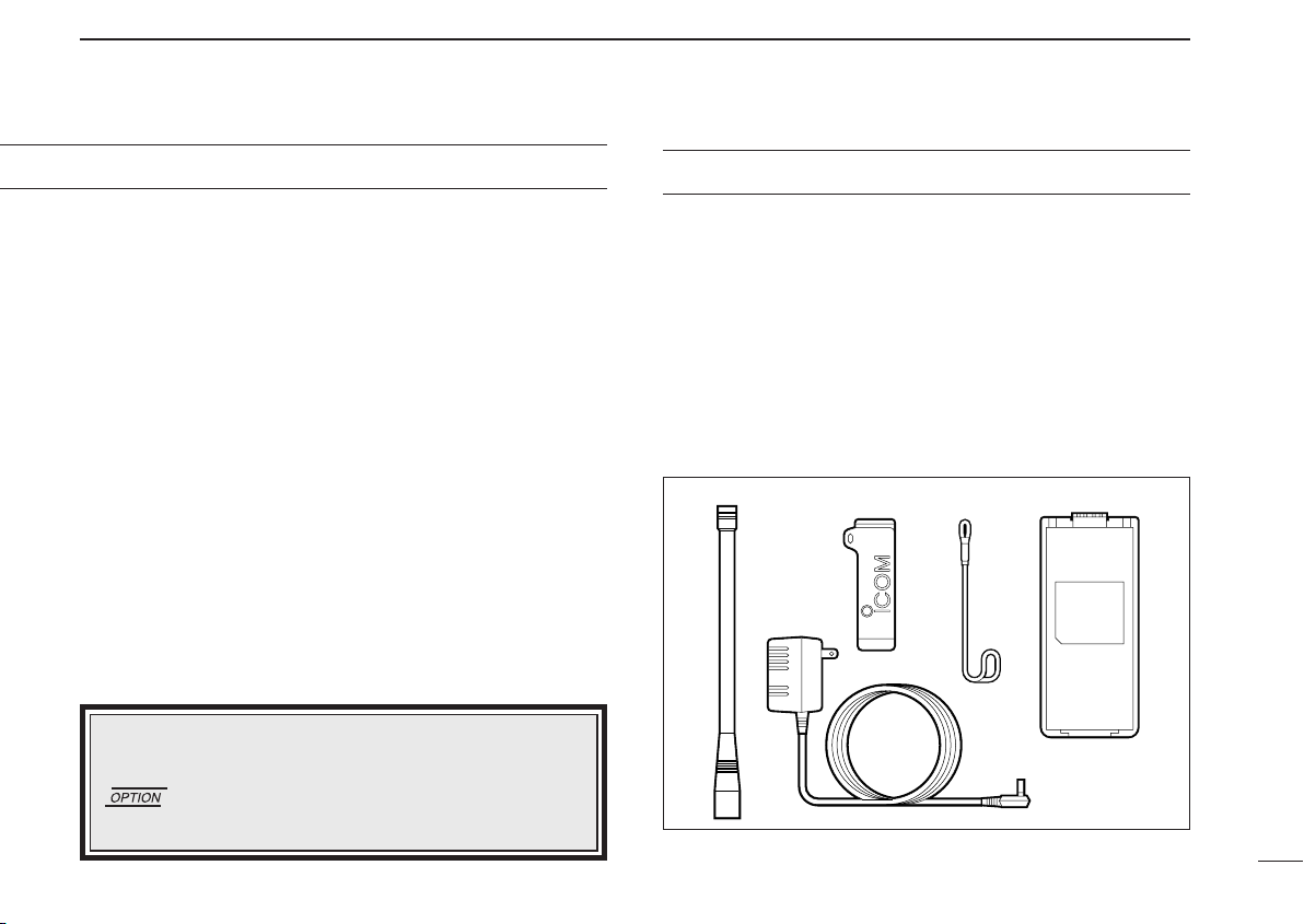
Accessories included with the transceiver: Qty.
q Antenna .......................................................................... 1
w Belt clip ........................................................................... 1
e Handstrap ........................................................................ 1
r Battery pack or battery case with Ni-Cd batteries* ... 1 set
t Wall charger* .................................................................. 1
*The battery pack(BP-195 or BP-196), battery case or wall
charger may differ depending on version. Some versions do not
include a battery pack and wall charger.
ii
Page 4

TABLE OF CONTENTS
FOREWORD ........................................................................ i
EXPLICIT DEFINITIONS ..................................................... i
CAUTIONS .......................................................................... i
SUPPLIED ACCESSORIES................................................. ii
TABLE OF CONTENTS ...................................................... iii
1 ACCESSORY ATTACHMENT ....................................... 1
2 PANEL DESCRIPTION ............................................ 2 – 4
■ Panel description ................................................... 2– 3
■ Function display .......................................................... 4
3 BASIC OPERATION ................................................ 5 – 7
■ Receiving and transmitting ......................................... 5
■ Setting squelch level ................................................... 6
■ Side tone function ....................................................... 6
■ Lock function .............................................................. 6
■ Display backlighting .................................................... 6
■ Low battery indicator .................................................. 6
■ Dial select function ..................................................... 7
4 SCAN OPERATION ...................................................... 8
■ Memory (lockout) scan ............................................... 8
■ VFO (full) scan ............................................................ 8
5 MEMORY PROGRAMMING .................................. 9– 10
■ Programming a memory channel ............................... 9
■ Memory names ......................................................... 10
6 OTHER FUNCTIONS .................................................. 11
■ Initial set mode .......................................................... 11
■ Resettng the CPU ..................................................... 11
7 BATTERY PACKS ................................................ 12– 14
■ Charging precautions ............................................... 12
■ Battery pack charging ............................................... 12
■ About the battery pack .............................................. 14
■ Installing batteries in the battery case ...................... 14
8 CLONING .................................................................... 15
9 TROUBLESHOOTING ................................................ 16
10 SPECIFICATIONS ....................................................... 17
11 OPTIONS ..................................................................... 18
iii
Page 5
ACCESSORY ATTACHMENT
1
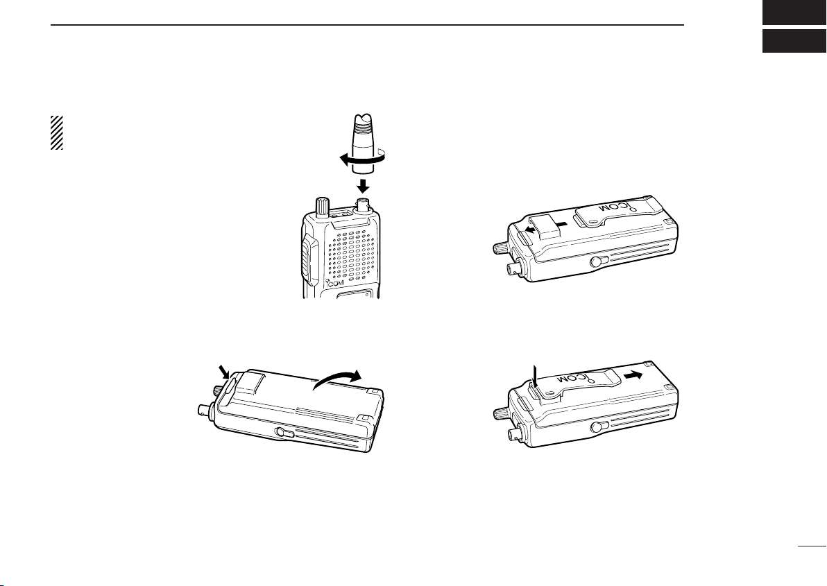
D Antenna
CAUTION:
antenna may damage the transceiver.
Insert the supplied antenna into the antenna connector and screw down the antenna as shown at right.
Keep the jack cover attached when jacks
are not in use to avoid bad contacts from
dust and moisture.
Transmitting without an
D Battery pack replacement
To remove:
Push and hold the battery release downwards,
then pull the battery pack
upwards as shown at
right.
To attach:
Mate the notched ends of the battery pack and the transceiver, and push the battery pack until it clicks into place.
D Belt clip
Conveniently attaches to your belt.
To attach:
Slide the belt clip into the plastic loop on the back of the battery case/pack.
To remove:
Push the top of the belt clip towards the transceiver and at
the same time, push it downward and free of the plastic loop.
1
Page 6
2
PANEL DESCRIPTION
■ Panel description
q
w
e
r
t
y
!4
!3
!2
!1
!0
o
i
u
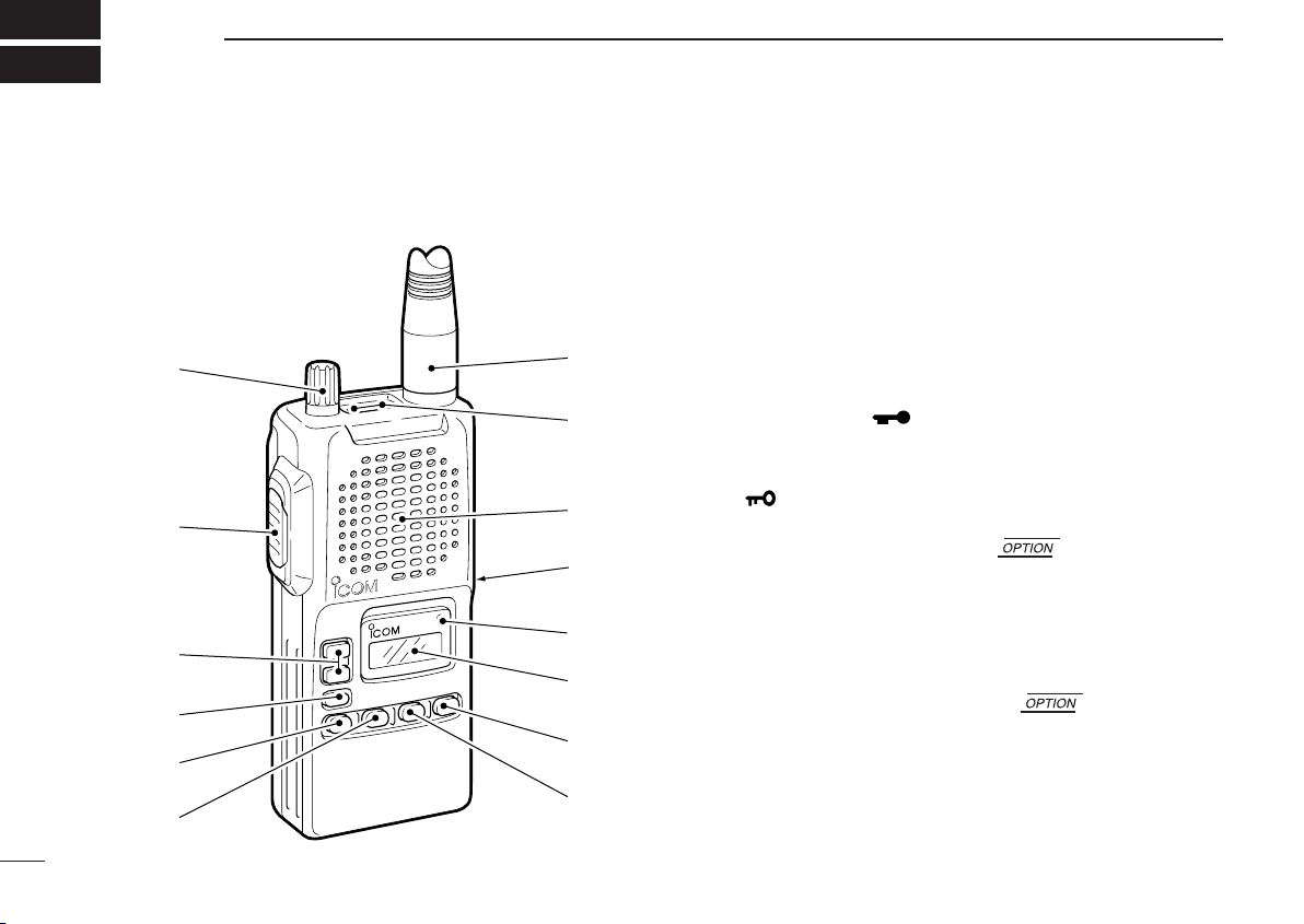
q VOLUME CONTROLS [VOL] (p. 5)
Turns power ON and adjusts the audio level.
w PTT SWITCH [PTT] (p. 5)
Push and hold to transmit; release to receive.
e CHANNEL UP/DOWN SWITCHES [Y]/[Z]
➥ Push to select the operating channel or frequency. (p. 5)
➥ Select item conditions in set mode.
r LOCK SWITCH [ ]
➥ Push and hold 2 sec. to toggle the key lock function ON
or OFF. (p. 6)
“ ” appears on the display.
•
t VFO/MEMORY SWITCH [V/M] *
➥ Push to select VFO mode or
memory mode. (pgs. 5, 8)
• “X” appears when memory mode is selected.
• The transceiver has 19 memory channels.
y MEMORY WRITE SWITCH [MW] *
➥ Push and hold for 5 sec. to write
information into memory channels. (p. 9)
u SCAN SWITCH [SCAN]
➥ Starts and stops the scan function:
2
Page 7

PANEL DESCRIPTION
2
VFO mode: VFO scan function. (option)
MEMORY mode: Memory channel scan function. (p. 10)
➥When memory mode is selected, this switch sets the
displayed channel as a scan lock-out channel when
pushed for 2 sec. (option)
• “SKIP” appears on the display.
i SQUELCH SWITCH [SQL]
➥ Push and hold to open the squelch. (p. 6)
➥ While pushing [SQL], push [Y]/[Z] to select the
squelch level. (p. 6)
• 9 squelch levels and squelch open are available.
o FUNCTION DISPLAY (p. 4)
!0 TRANSMIT INDICATOR
Lights red while transmitting.
!1 EXTERNAL DC POWER JACK [CHARGE]
Connect a 12 to 16 V DC power source using the optional
cables, CP-12L or OPC-254L, to charge the attached battery pack; or connect the BC-110V wall charger for charging.
CAUTION:This connection is for charging ONLY. Power
to the transceiver must be turned OFF during charging.
!2 SPEAKER/MICROPHONE
!3 EXTERNAL SPEAKER AND MICROPHONE JACKS
[SP/MIC]
➥ Connect an optional speaker-microphone or headset, if
desired. The internal microphone and speaker will not
function when either is connected. (See p. 18 for a list
of available options.)
➥ Side tone function is available when an optional head-
set adapter is connected. (pgs. 6, 18)
!4 ANTENNA CONNECTOR (p. 1)
Connects the supplied antenna.
*NOTE: The VFO/memory switch [V/M] and the memory
write switch [M/W] functions may not be available depending on version.
3
Page 8
PANEL DESCRIPTION
MR
SKIP
2
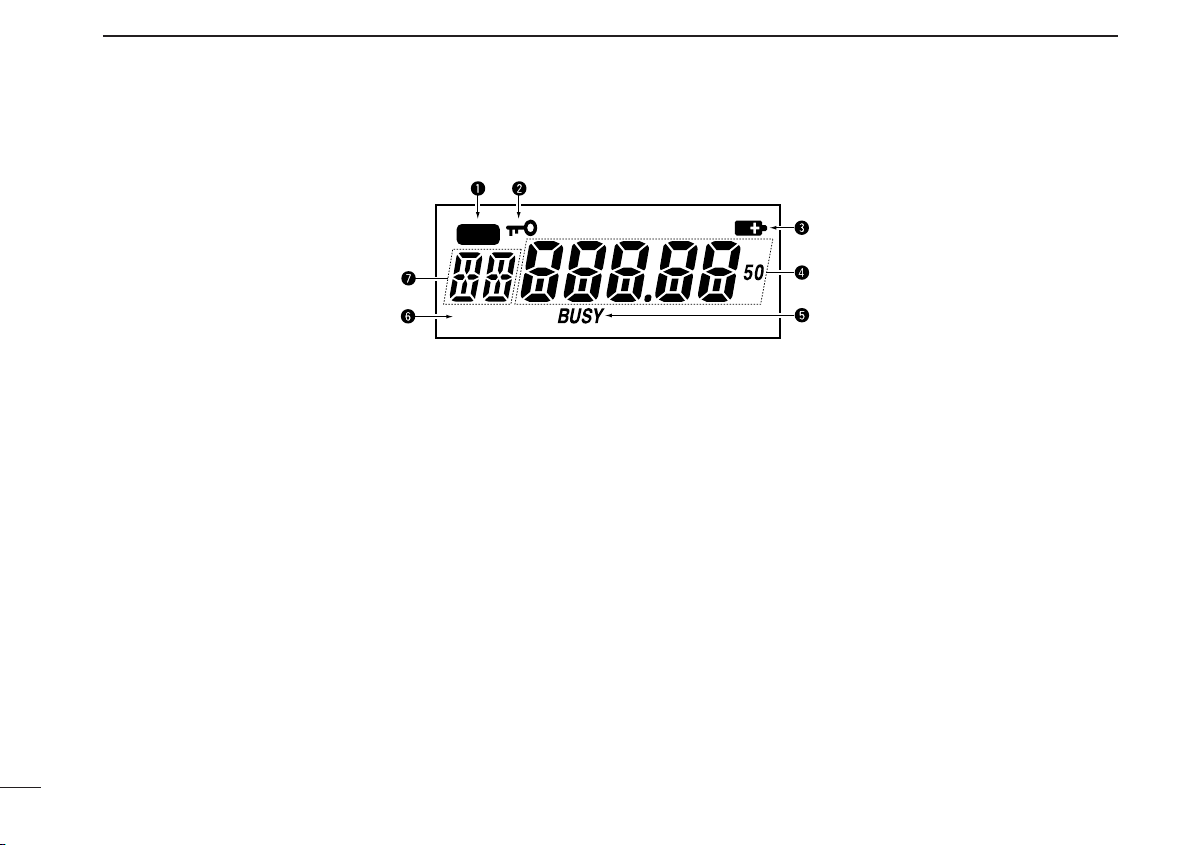
■ Function display
q MEMORY MODE INDICATOR (p. 9)
Appears when memory mode is selected.
w LOCK INDICATOR (p. 6)
Indicates that the lock function is in use.
e LOW BATTERY INDICATOR
➥ Appears when the battery is nearing exhaustion.
➥ Appears and flashes when battery replacement is nec-
essary.
r FREQUENCY DISPLAY (p. 11)
➥Shows the operating frequency.
➥Shows the channel name when the memory name func-
tion is selected. (p. 10)
t BUSY INDICATORS
➥ “BUSY” appears when receiving a signal or when the
squelch is open.
y MEMORY LOCKOUT INDICATOR
➥ “SKIP” appears when the memory channel is set as
lockout channel.
u MEMORY CHANNEL INDICATOR
➥Shows the memory channel number.
➥When the transceiver output power increases above a
specified level, a protection circuit stops the transmitting,
then “--” appears on the display instead of the memory
channel number. Release [PTT] then push it again to
continue transmitting.
4
Page 9

BASIC OPERATION
q Set volume
e [SQL] switch
r Speak into
microphone
r Push to transmit
t Release to
receive
e Select channel
or frequency
w [V/M] switch
3
■ Receiving and transmitting
CAUTION: Transmitting without an antenna may dam-
age the transceiver.
q Rotate [VOL] clockwise to turn power ON, then set to the
10 o’clock position.
w Push [V/M]* to select memory mode (or VFO mode: *op-
tion).
e Select the desired memory channel (or VFO frequency)
with the [Y]/[Z] keys.
•When receiving a signal, “BUSY” appears and audio is emitted
from the speaker.
• Further adjustment of [VOL] may be necessary at this point.
• Push [SQL] to toggle the squelch function ON and OFF. (p. 6)
•When the dial select function is selected, each push increments/decrements the frequency either 100 kHz or 1 MHz. (p. 7)
r Push and hold [PTT] to transmit, then speak into the mi-
crophone.
• Transmit indicator lights.
t Release [PTT] to receive.
ï Memory ➾ VFO
Memory channel contents can be moved to VFO .
q Select memory channel to be transferred:
➥ Push [V/M] to select memory mode, if necessary.
➥ Push [Y] or [Z] to select the memory channel.
w Push [V/M] key for 2 sec. to transfer the memory contents
to VFO.
• VFO mode is selected.
NOTE:
• Only frequency data is transferred even if the memory
channel has a memory name.
•When the preprogrammed memory frequency is outside
the range of the preprogrammed VFO edges, an error
beep tone sounds and no data is transferred.
5
Page 10

BASIC OPERATION
MR
“ ” appears when the
lock function is in use.
MR
SKIP
3
6
■ Setting squelch level
The transceiver has a noise squelch circuit to mute undesired
noise while receiving no signal.
➥ To open the squelch:
Push and hold [SQL] to open the squelch. This is useful to
listen to weak signals that do not open the squelch.
• “BUSY” appears on the display.
➥ To close the squelch:
Release [SQL] to close the squelch.
D Setting the squelch level
q While pushing [SQL], push [Y] or [Z] to select the squelch
level.
• ‘Sq 1’ is loose squelch and ‘Sq 9’ is tight squelch. (Initial
level is ‘Sq 5’)
• ‘oPEn’ indicates that the squelch circuit is turned off.
w Release [SQL] to return to regular operation.
■ Side tone function
When using an optional headset, such as those from the
David Clark Co. via the OPC-752
transceiver outputs your transmitted voice to the headset for
monitoring. (p. 18)
HEAD SET ADAPTOR, the
■ Lock function
The lock function prevents accidental channel changes and
accidental function access. [PTT] and [SQL] still function
while the lock function is in use.
➥ Push [ ] for 2 sec. to toggle the lock function ON and OFF.
■ Display backlighting
Display backlighting automatically turns on when a key is
pushed.
■ Low battery indicator
Low battery indicator appears
when the battery power has decreased to a specified level.
Page 11
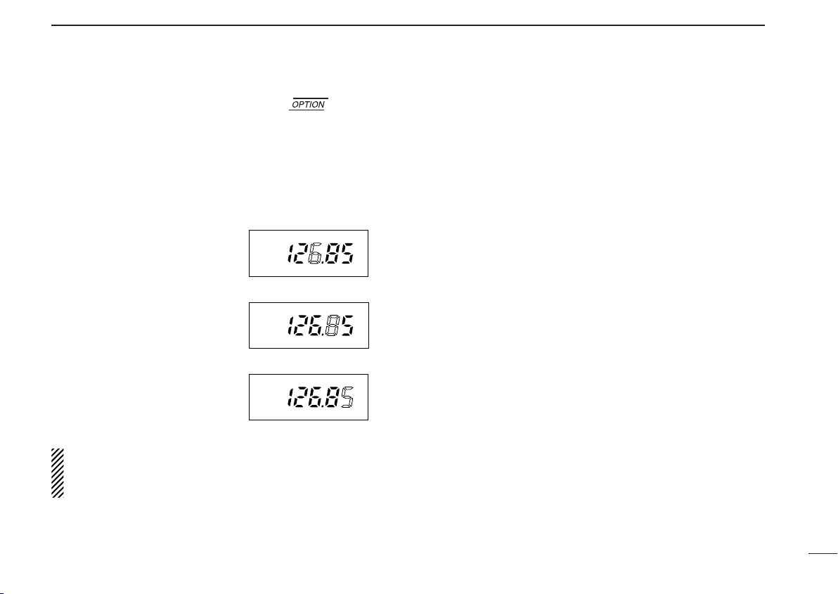
■ Dial select function
1 MHz tuning selected
100 kHz tuning selected
Regular tuning selected
Use the dial select function to adjust the tuning behavior of
the [Y]/[Z] keys—use 1 MHz tuning when you want to
change the frequency in large increments; use regular tuning
when you want to change the frequency in smaller increments.
q Push [V/M] to select VFO
mode.
w Push [V/M] for 2 sec. one or
more times to select the desired tuning increment.
• 1 MHz tuning, 100 kHz tun-
ing or regular tuning steps
can be selected. (see diagrams at right)
e Push any key to return to nor-
mal operation.
NOTE: Large tuning steps should be used only when you
want to change the frequency in large increments. Please
select regular tuning steps for normal operation.
BASIC OPERATION
3
7
Page 12

4
MR
MEMORY LOCKOUT(SKIP) SCAN
SKIP
SKIP
Mch 1
Mch 7
Mch 2 Mch 4
Mch 3 Mch 5 Mch 6
Mch 8
Mch 19 Mch 11 Mch 10 Mch 9
VFO SCAN (Full scan)
Scan
Jump
Start
highest
frequency
lowest
frequency
SCAN OPERATION
■ Memory (lockout) scan
Memory scan repeatedly scans all programmed memory
channels, except those set as lockout channels.
q Push [V/M] to select memory mode, if necessary.
• “ ” appears.
w Puch [SCAN] to start scan.
• To change the scan direction, push [Y] or [Z].
e Push [SCAN] again to stop the scan.
8
■ VFO (full) scan
VFO scan repeatedly scans between the VFO’s lowest
frequency and its highest frequency.
• To change the scan direction, push [Y] or [Z] during
scanning.
D Scan resume condition
When a signal is received during scanning, the scan pauses
on the signal until it disappears, then resumes.
NOTE: The VFO/memory switch [V/M] and the memory
write switch [M/W] functions may not be available depending on version.
Page 13

MR
■ Programming a memory
MR
MR
MR
MR
SKIP
Memory channel 15 is
set as a lockout channel.
channel
MEMORY PROGRAMMING
5
The transceiver has 19 memory channels for storage of often
-used frequencies.
q Push [V/M] to select VFO
mode, if necessary.
w Push [Y] or [Z] to select the
desired frequency.
• Push [V/M] one or more times
to use the dial select function, if
desired.
e Push [MW] for 5 sec. to enter
memory programming mode.
•“ ” and memory channel
number appear.
r Push [Y] or [Z] to select the
desired memory channel
number.
t Push [MW] for 2 sec. to pro-
gram the information into the
channel and return to VFO
mode.
D Setting lockout channels
In order to speed up the scan interval, you can set memory
channels you don’t wish to scan as lockout channels.
q Push [V/M] to select memory mode, if necessary.
• “ ” appears.
w Push [Y] or [Z] to select a memory channel to set as a
lockout channel.
e Push [SCAN] for 2 sec. to toggle the lockout setting
ON/OFF.
•“SKIP” appears when the channel is set as a lockout channel.
•If memory channel scan is accidentally started, push [SCAN] to
stop it.
*NOTE: The VFO/memory switch [V/M] and the memory
write switch [M/W] functions may not be available depending on version.
9
Page 14

MEMORY PROGRAMMING
MR
MR
MR
[EXAMPLE]: Setting the name to “TOWER”.
SCAN
+
MW
MW
SQL
or
or
MR
5
■ Memory names
ï Programming memory names
q Select the memory channel to be programmed:
➥ Push [V/M] to select memory mode.
➥ Push [Y] or [Z] to select the memory channel.
w Push [M/W] for 5 sec. to enter memory name writing mode.
• The first character of the name flashes.
e Push [SCAN] or [SQL] as many times as necessary to
enter the desired name.
• To erase a character, overwrite with a space (displayed as _).
•To move the cursor forwards or backwards, use [Y] or [Z].
• Push [ ]
r Push [M/W] to input the set name.
• Flashing stops.
•Memory channels can be programmed with names of up to 5
characters in length.
•When no name is programmed, the display shows the operating
frequency.
for 2 sec. to erase all characters.
for 5 sec.
• The following characters can be used in names:
➥ 0 to 9, A to Z (capitals), (space), “-”, #, $, &, (, ), “,”, •, /,
<, >, =, “, ‘, ?, ! and @.
for 2 sec.
10
Page 15
OTHER FUNCTIONS
6
■ Initial set mode
Initial set mode is accessed at power ON and allows you to
set seldom-changed settings. In this way you can “customize”
transceiver operations to suit your preferences and operating
style.
D Entering initial set mode
q While pushing [V/M] + [ ], turn power ON.
•The transceiver enters initial set mode and “mn”, “bP” or “St” appears on the display.
w Push[Y] or [Z] one or more times to select the desired
item as described below and at right.
e Push [ ] to select the desired condition.
r Push [MW] or [PTT] to exit initial set mode and select the
previous operating mode.
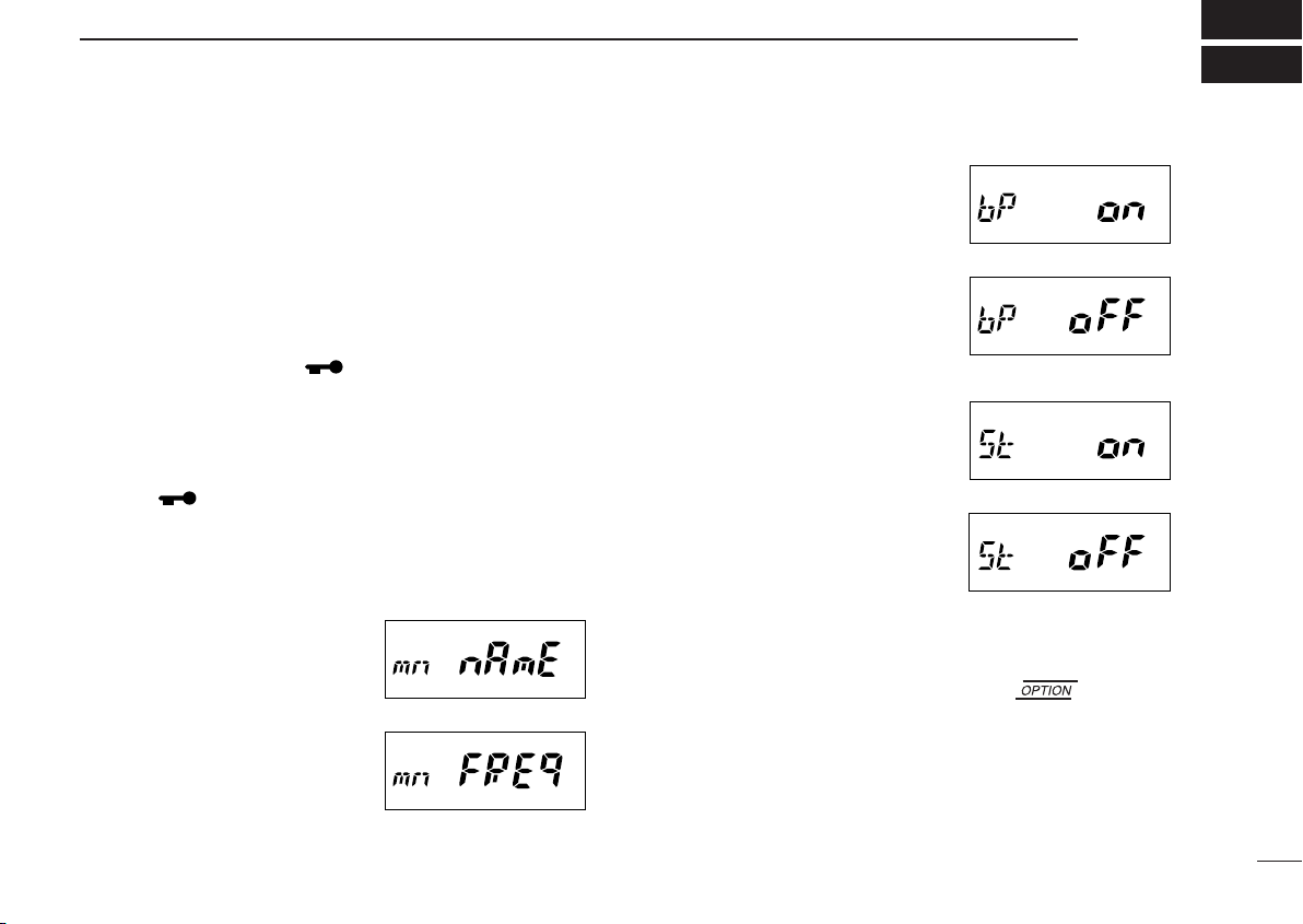
D Memory names
This item allows you to display a
memory name instead of frequency.
•When a memory channel has
not been programmed with a
name, frequency indication appears instead.
D Beep tones ON/OFF
Confirmation beep tones normally sound when you push a
key. These can be turned ON or
OFF as you prefer.
D Side tones ON/OFF
When using an optional headset
such as those from the David
Clark Co. via the adapter, the
transceiver outputs your transmitted voice to the headset for
monitoring.
• Optional OPC-752 HEADSET
ADAPTER
is required.
■ Resetting the CPU
Reset the CPU before operating the transceiver for the first
time, or when the internal CPU malfunctions.
➥ While pushing [V/M] + [MW] + [SCAN], turn power ON to
reset the transceiver.
•“CLEAR” appears briefly to indicate the CPU has been reset.
11
Page 16

7
BATTERY PACKS
■ Charging
precautions
NEVER attempt to charge dry cell bat-
teries. This will cause internal liquid
leakage and damage the battery case
and transceiver.
NEVER connect two or more chargers
at the same time.
Charging may not occur under temperatures of 10°C (50°F) or over temperatures of 40°C (104°F).
When using BC-119: If the charge
indicator flashes orange, vehicle battery voltage is low and charging is
not possible. Check the vehicle battery voltage in this case. If the
charge indicator flashes red, there
may be a problem with the battery
pack (or charger). Re-insert the battery pack or contact your dealer.
■ Battery pack
charging
The BP-195 or BP-196
includes rechargeable Ni-Cd batteries
and can be charged approx. 300 times.
Charge the battery pack before first operating the transceiver or when the battery pack becomes exhausted.
If you want to be able to charge the battery pack more than 300 times, the following points should be observed:
1. Avoid overcharging. The charging pe-
riod should be less than 48 hours.
2.Use the battery until it becomes al-
most completely exhausted under
normal conditions. We recommend
battery charging just after transmitting
becomes impossible.
BATTERY PACK
D
Rapid charging with the BC-119
The optional BC-119 provides rapid
charging of battery packs.
One AD-81 and an AC adapter (may be
supplied with the BC-119 depending on
version) are additionally required.
• Charging periods: 1.5 hours (w/BP-195)
2 hours (w/BP-196)
Turn power
OFF.
BC-119+
AD-81
BC-119+
AD-81
Check orientation
for correct charging.
(Packed together
as the AD-81.)
Check orientation
for correct charging.
(Packed together
as the AD-81.)
12
Page 17

BATTERY PACKS
IC-A4 with
attached
battery case
(pack)
BC-110A/D/V
CP-12L
(optional)
OPC-254L
(optional)
To a 12 to
16 V DC
power source
To
[CHARGE]
white
black
M
U
L
T
I-C
H
A
R
G
E
R
AC adapter
(not supplied with some versions)
Charge indicator
(each indicator function
independently)
7
D Multiple charging with the BC-121
The optional BC-121 allows up to 6 battery packs to be
charged simultaneously.
Six AD-81’s and an AC adapter (may be supplied with the
BC-121 depending on version) are additionally required.
• Charging periods: 1.5 hours (w/BP-195)
2 hours (w/BP-196)
D Regular charging
q Attach the battery pack to the transceiver.
w Be sure to turn the transceiver power OFF.
e Connect the AC adapter (BC-110A/D/V) or optional cable
(CP-12L or OPC-254L) as shown below.
• Charging periods: 10 hours (w/BP-195)
15 hours (w/BP-196)
13
Page 18
BATTERY PACKS
RBRC
RBRC
Ni-
Cd
7
■ About the battery pack
D Operating period
Depending on the attached battery pack, the operating period
of the transceiver varies. Refer to OPTIONS for battery pack
specifications.
D Battery pack life
If your battery pack seems to have no capacity even after
being fully charged, completely discharge it by leaving the
power ON overnight. Then, fully charge the battery pack
again.
If the battery pack still does not retain a charge (or very little),
a new battery pack must be purchased.
D Recycling information (U.S.A only)
The product that you have purchased may
contain a rechargeable battery. The battery
is recyclable. At the end of its life, under various state and local laws, it may be illegal to
dispose of this battery into the municipal
waste stream. Call 1-800-8-BATTERY for
battery recycling options in your area or contact your dealer.
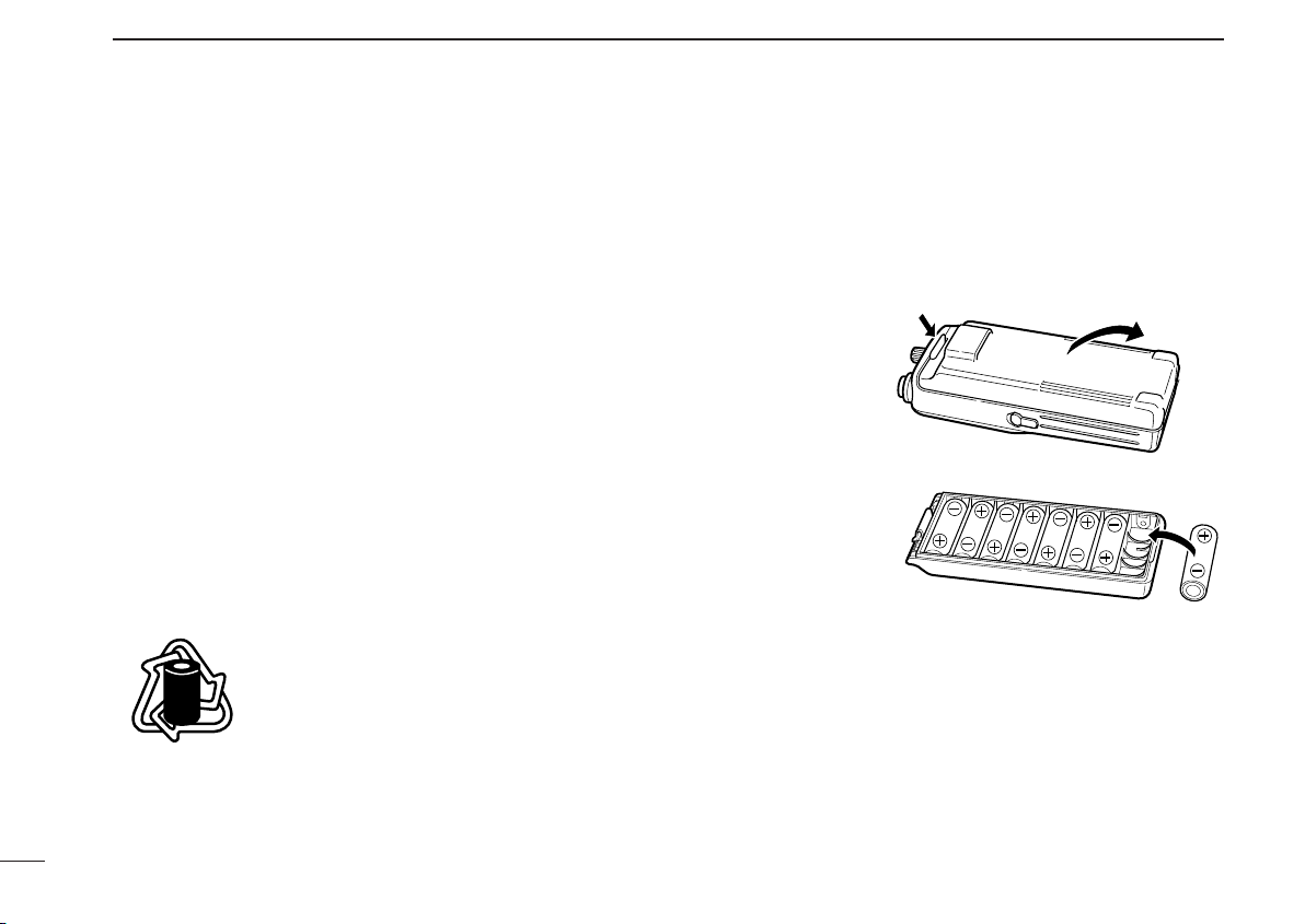
■ Installing batteries in the
battery case
When using a battery case, install 8 AA (R6) size Ni-Cd or alkaline batteries as illustrated below.
q Remove the bat-
tery case from the
transceiver.
w Install 8 × AA (R6)
size Ni-Cd or alkaline batteries.
•Be sure to observe
the correct polarity.
● NEVER connect DC power to the transceiver when in-
stalling dry cell or alkaline batteries. Such a connection will
damage the transceiver.
● Be careful of battery overcharging. When operating via external DC power, installed batteries are simultaneously
charged.
● Keep battery contacts clean. It’s a good idea to clean bat-
tery terminals once a week.
14
Page 19

CLONING
8
Cloning allows you to quickly and easyly
transfer the programmed contents from
one transceiver to another transceiver, or, data from PC to a
transceiver using the optional EX-2119 cloning software.
]
D Transceiver to transceiver cloning
q Connect the OPC-474
the [SP] jack of the master and slave transceivers.
• The master transceiver is used to send data to the slave transceiver.
w While pushing [Y] + [Z] + [V/M], turn power ON to enter
cloning mode (master transceiver only—power ON only for
slave transceiver).
•“CLonE” appears and the transceivers enter the clone
standby condition.
e Push [PTT] on the master
transceiver.
•“CLoUt” appears in the mas-
ter transceiver’s display.
•“CL in” appears automati-
cally in the slave transceiver’s display.
e When cloning is finished, turn
power OFF, then ON again to
exit cloning mode.
CLONING CABLE with adapter plugs to
D Cloning using PC
Data can be cloned to and from a PC (IBM compatible) using
the optional EX-2119
478
CLONING CABLE. Consult the EX-2119 CLONING SOFTWARE HELP
message for details.
CLONING SOFTWARE and the optional OPC-
D Cloning error
NOTE: DO NOT push [PTT] on the slave transceiver dur-
ing cloning. This will cause a cloning error.
When the display at right appears, a cloning error has occurred.
In this case, both transceivers automatically return to the
clone standby condition and cloning must be repeated.
15
Page 20

9
POSSIBLE CAUSE SOLUTION REF.
No power comes on. • The battery is exhausted.
• Bad connection to the battery pack.
• Recharge the battery pack.
• Check the connection to the
transceiver.
pgs. 12,
14
No sound comes from the
speaker.
• Squelch level is too deep.
• Volume level is too low.
• Set squelch to the threshold point.
• Set [VOL] to a suitable level.
pgs. 5, 6
Transmitting impossible. • Some channels are receive only.
• The battery is exhausted.
• Change channels.
• Recharge the battery pack.
p. 5
p. 12
The displayed channel
cannot be selected.
• Lock function is activated.
• Push for 2 sec. to cancel the
function.
p. 6
Scan does not start. • All memory channels are programmed
as lockout channels.
• Cancel the lockout settings of
desired channels.
p. 9
No beep sounds. • Beep tones turned OFF. • Turn the beep tone ON in set mode. p. 11
PROBLEM
If your transceiver seems to be malfunctioning, please check
the following points before sending it to a service center.
TROUBLESHOOTING
16
Page 21

SPECIFICATIONS
10
D General
• Frequency coverage : Tx 118 to 136.975 MHz
Rx 108 to 136.975 MHz
• Mode : AM (6K00A3E)
• Number of memory channels : 19
•Acceptable power supply : 9.6 V DC nominal
(negative ground) (authorized battery packs)
• Usable temp. range : –10˚C to +50˚C
• Frequency stability : ±10 ppm (0˚C to +50˚C)
• Current drain :
Tx 1.2 A (CW) max.
0.7 A (CW) typical
Rx 55 mA typical (at standby)
250 mA max. (at AF max.)
• Antenna impedance : 50 Ω (nominal)
•Dimensions : 58(W)✕140.5(H) ✕ 32.3(D) mm
(projections not incl.)
• Weight (with BP-195) : 425 g
D Transmitter
• Output power : 3.7 W (PEP) typical
1.0 W (CW) typical
• Modulation : Low level modulation
• Modulation limiting : 80 to 100 %
• Audio harmonic distortion : Less than 10 %
(at 60 % modulation)
• Hum and noise ratio : More than 35 dB
• Spurious emissions : More than 60 dB
D Receiver
• Receive system : Double conversion
superheterodyne
• Intermediate frequencies : 1st 28.95 MHz
2nd 450 kHz
•Sensitivity (with 50 Ω load) : 1 µV (at AM 6dB S/N)
• Squelch sensitivity : 1 µV
(with 50 Ω load)
• Selectivity : 8 kHz (at 6 dB)
25 kHz (at 60 dB)
• Spurious response : More than 60 dB
•Audio output power : 500 mW (at 10% distortion
(at 9.6 V DC) with an 8 Ω load)
• Noise and hum : More than 25 dB
• External SP connector : 3-conductor 3.5 (d) mm/8 Ω
All stated specifications are subject to change without
notice or obligation.
17
Page 22

11
yrettaB
kcap
egatloV yticapaC
doirepgnigrahC
gnitarepO
*doirep
1
llaW
regrahc
ro911-CB
121-CB
18-DAhtiw
491-PB
AArofesacyrettaB
)6R( × roenilakla8
sllecdC-iN
*srh01
2
A/N*srh6
2
591-PB V6.9hAm007srh01srh5.1srh6
691-PB V6.9
0501
hAm
srh51srh0.2srh0.9
OPTIONS
D Battery packs
1
Operating periods are calibrated for the following conditions:
at 25°C (77°F), Tx (high power) : Rx : standby = 5 : 5 : 90
*2When Ni-Cd batteries are installed.
D Other options
BC-110A/D/V WALL CHARGER
Used for regular charging of the connected battery pack.
BC-119
For rapid charging of battery packs. An AC adapter is supplied with the charger. Some BC-119 versions require the AD75 additionally. Charging time: 1.5 to 2 hrs.
BC-121
For rapid charging up to 6 battery packs simultaneously. An
AC adapter may be supplied depending on version. Six AD81’s are necessary. Charging time: 1.5 to 2 hrs.
18
DESKTOP CHARGER + AD-81 CHARGER ADAPTOR
MULTI-CHARGER
+ AD-81
CHARGER ADAPTOR
OPC-254L
CP-12L
DC POWER CABLE
CIGARETTE LIGHTER CABLE WITH NOISE FILTER
Allows you to charge a battery pack connected to the transceiver via a DC power source (12–16 V DC) For charging
ONLY—the transceiver cannot be simultaneously operated.
HM-119
SPEAKER MICROPHONE
Combination speaker and microphone.
SP-13
EARPHONE
Provides clear audio in noisy environments.
OPC-752
HEADSET ADAPTER
When using an optional headset, such as those from the
David Clark Co. via the adapter
, the transceiver outputs your
transmitted voice to the headset for monitoring. (p. 19)
EX-2119
FIELD PROGRAMMING SOFTWARE
Provides quick and easy programming of items, including private channels, scan settings, etc., via an IBM
®
compatible PC
to transceiver.
OPC-474
CLONING CABLE
Cloning cable for transceiver to transceiver.
OPC-478
Cloning cable for PC to transceiver.
IBM®is a registered trademark of International Business Machines.
CLONING CABLE
Page 23

OPTIONS
11
D OPC-752 (HEADSET ADAPTER)
When using an optional headset, such as those from the
David Clark Co. via the adapter
transmitted voice to the headset for monitoring. (pgs. 6, 11)
IC-A4
connection
, the transceiver outputs your
OPC-752
Clip the cable to the
handstrap loop on
the beltclip for support.
PTT
PTT switch
Use a PTT switch
with a 3.5 mm diameter plug, if required.
HEADSET
(Must be purchased
separately.)
19
Page 24

Count on us!
A-5523H-1EX
Printed in Japan
© 1998 Icom Inc.
6-9-16 Kamihigashi, Hirano-ku, Osaka 547-0004 Japan
 Loading...