

Page 1

THE TRANSCEIVER
i7850
Instruction Manual
A-7199H-1EX-0a
Printed in Japan
© 2015 Icom Inc.
Page 2

FOREWORD
Previous view
Thank you for choosing the IC-7850. The IC-7850 has many built-in high technology circuitry and unique functions, such as the Dualwatch on the Main and
Sub bands, a high speed spectrum scope scan, a high-resolution waterfall
screen, and many other outstanding features.
The internal frequency signals in a radio utilizing a PLL are not always sufficiently pure. This results in a considerable number of unwanted spurious
components, called phase noise, in its frequency spectrum. We focused intensively in drastically reducing the phase noise of LO (Local Oscillator) because
the phase noise degrades the interference rejection and noise characteristics
of the receiver. As a result, we succeeded in developing an LO with high purity outputs so that results in an RMDR (Reciprocal Mixing Dynamic Range)
of 101dB with newly developed 1.2kHz Optimum Roofing Filter. Currently no
competitors have been able to achieve this extremely high result performance.
We believe we would not have been able to exceed the standard specifications without our full focus on LO purity.
In addition, Icom that has chosen to base the IC-7850 on an up-conversion,
double super-heterodyne receiver design, which has many advantages over
traditional receiver designs.
We are proud to have developed the IC-7850 for your amateur radio activities,
and hope it brings you years of enjoyable operation.
Please read this instruction manual thoroughly before using the IC-7850.
i
Page 3

IMPORTANT
Previous viewPrevious view
READ THIS INSTRUCTION MANUAL CAREFULLY before at-
tempting to operate the transceiver.
SAVE THIS INSTRUCTION MANUAL. This manual contains important
safety and operating instructions for the IC-7850.
EXPLICIT DEFINITIONS
R DANGER!
R WARNING!
CAUTION
TRADEMARKS
Icom, Icom Inc. and the Icom logo are registered trademarks of Icom
Incorporated (Japan) in Japan, the United States, the United Kingdom,
Germany, France, Spain, Russia and/or other countries.
WORD DEFINITION
Personal death, serious injury or an explosion may occur.
Personal injury, fire hazard or electric shock may occur.
Equipment damage may occur.
NOTE
Recommended for optimum use. No risk of personal injury, fire or electric shock.
This product includes “zlib” open source software, and is licensed according to the open source software license.
This product includes “libpng” open source software, and is licensed according to the open source software license.
Refer to the Text files in the License folder of included CD for information on the open source software being used
by this product.
ii
Page 4

PRECAUTIONS
Previous viewPrevious view
R DANGER HIGH RF VOLTAGE! NEVER
attach an antenna or internal antenna connector
during transmission. This may result in an electrical
shock or burn.
R WARNING! NEVER operate the transceiver
with a headset or other audio accessories at high
volume levels. The continuous high volume operation
may cause a ringing in your ears. If you experience
the ringing, reduce the volume level or discontinue
use.
R WARNING! NEVER operate or touch the
transceiver with wet hands. This may result in an electric shock or damage to the transceiver.
R WARNING! NEVER let metal, wire or other ob-
jects protrude into the transceiver or into connectors
on the rear panel. This may result in an electric shock.
R WARNING! Immediately turn the transceiver
power OFF and remove the power cable if it emits an
abnormal odor, sound or smoke. Contact your Icom
dealer or distributor for advice.
CAUTION: NEVER put the transceiver in any un-
stable place (such as on a slanted surface or vibrated
place). This may cause injury and/or damage to the
transceiver.
CAUTION: NEVER put the transceiver’s rear
panel side down after lifting up the transceiver by
holding rack mounting handle. This may scratch the
surface of the place or damage the connectors on the
transceiver’s rear panel.
CAUTION: NEVER change the internal settings
of the transceiver. This may reduce transceiver performance and/or damage to the transceiver.
In particular, incorrect settings for transmitter circuits,
such as output power, idling current, etc., might damage the expensive final devices.
The transceiver warranty does not cover any problems caused by unauthorized internal adjustment.
CAUTION: NEVER block any cooling vents on the
top, rear or bottom of the transceiver.
CAUTION: NEVER expose the transceiver to rain,
snow or any liquids.
CAUTION: The transceiver weighs approximately
23.5 kg (52 lb). Always have two people available to
carry, lift or turn over the transceiver.
CAUTION: The line-voltage receptacle must be
near the transceiver and must be easily accessible.
DO NOT use extension cords.
DO NOT
cohol when cleaning, as they can damage the transceiver’s surfaces.
DO NOT
ally desire to transmit.
use harsh solvents such as benzine or al-
push the PTT switch when you don’t actu-
DO NOT use or store the transceiver in areas with
temperatures below ±0°C (+32°F) or above +50°C
(+122°F).
DO NOT place the transceiver in excessively dusty
environments or in direct sunlight.
DO NOT place the transceiver against walls or
putting anything on top of the transceiver. This may
overheat the transceiver.
Always place unit in a secure place to avoid inadvertent use by children.
BE CAREFUL! If you use a linear amplifier, set the
transceiver’s RF output power to less than the linear
amplifier’s maximum input level, otherwise, the linear
amplifier will be damaged.
BE CAREFUL!
cover when transmitting continuously for long periods
of time. The top cover may be hot.
Use Icom microphones only (supplied or optional).
Other manufacturers’ microphones have different pin
assignments, and connection to the IC-7850 may
damage the transceiver or microphone.
The LCD display may have cosmetic imperfections
that appear as small dark or light spots. This is not a
malfunction or defect, but a normal characteristic of
LCD displays.
During maritime mobile operation, keep the transceiver and microphone as far away as possible from
the magnetic navigation compass to prevent erroneous indications.
NEVER touch the transceiver top
CAUTION: NEVER install the transceiver in a
place without adequate ventilation. Heat dissipation
may be reduced, and the transceiver may be damaged.
Turn [I/O] switch (on the rear panel) OFF and/or disconnect the AC power cable from the AC outlet when
you will not use the transceiver for long period of time.
iii
Page 5

FCC INFORMATION
Previous viewPrevious view
FOR CLASS B UNINTENTIONAL RADIATORS
This equipment has been tested and found to comply
with the limits for a Class B digital device, pursuant to
part 15 of the FCC Rules. These limits are designed to
provide reasonable protection against harmful interference in a residential installation. This equipment generates, uses and can radiate radio frequency energy
and, if not installed and used in accordance with the
instructions, may cause harmful interference to radio
communications. However, there is no guarantee that
interference will not occur in a particular installation.
If this equipment does cause harmful interference to
radio or television reception, which can be determined
by turning the equipment off and on, the user is encouraged to try to correct the interference by one or
more of the following measures:
• Reorient or relocate the receiving antenna.
• Increase the separation between the equipment
and receiver.
• Connect the equipment into an outlet on a circuit different from that to which the receiver is connected.
• Consult the dealer or an experienced radio/TV
technician for help.
This device complies with Part 15 of the FCC Rules.
Operation is subject to the following two conditions: (1)
this device may not cause harmful interference, and
(2) this device must accept any interference received,
including interference that may cause undesired operation.
WARNING: MODIFICATION OF THIS DEVICE TO
RECEIVE CELLULAR RADIOTELEPHONE SERVICE
SIGNALS IS PROHIBITED UNDER FCC RULES AND
FEDERAL LAW.
CAUTION: Changes or modifications to this device,
not expressly approved by Icom Inc., could void your
authority to operate this device under FCC regulations.
ABOUT THE SUPPLIED CD
The following instructions and installers are included
on the CD.
• Instruction manual
Instructions for the full operations, the same as this
manual
• Schematic diagram
Includes the schematic and block diagrams
• Adobe® Reader® Installer
Installer for Adobe® Reader
To read the Instruction manual or Schematic diagram,
Adobe® Reader® is required. If you have not installed it,
please install the Adobe® Reader® on the CD or downloaded it from Adobe Systems Incorporated’s web
A PC with the following Operating System is required.
• Microsoft® Windows® 8.1, Microsoft® Windows
8, Microsoft® Windows® 7 , or Microsoft® Windows
®
Vista
®
site.
®
D
Starting the CD
Insert the CD into the CD drive. q
• Double click “Menu.exe” on the CD.
• Depending on the PC setting, the Menu screen shown
below is automatically displayed.
Click the desired button to open the file. w
• To close the Menu screen, click [Quit].
Opens the
Instruction manual
(this manual)
Installs the Adobe® Reader
®
Opens the
Schematic diagram
Quits the menu screen
iv
Page 6
FUNCTIONS AND FEATURES of Adobe® Reader
Previous viewPrevious view
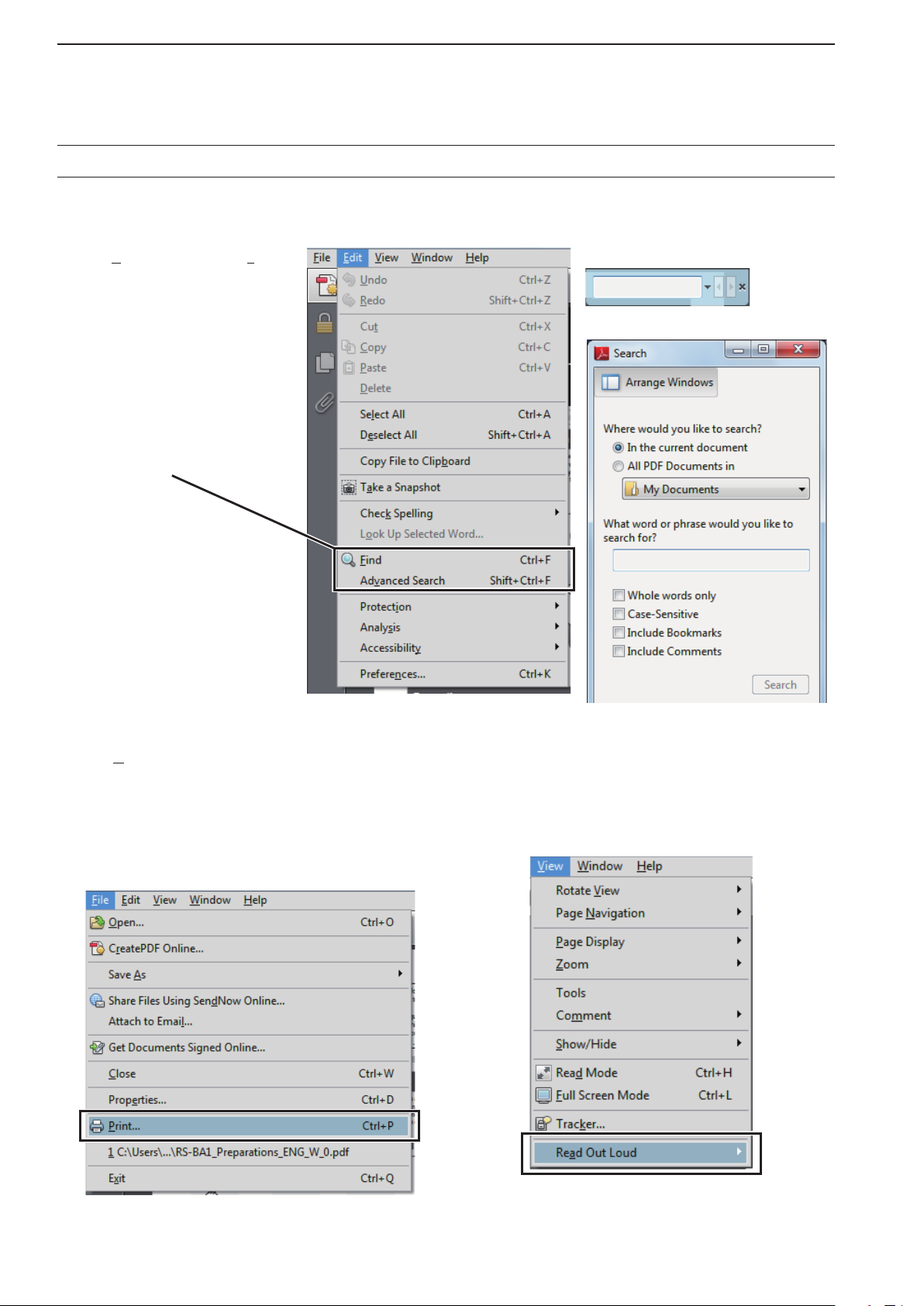
The following functions and features can be used with Adobe® Reader®.
• Keyword search
Click “Find (Ctrl+F)” or “Advanced
Search (Shift+Ctrl+F)” in the Edit
menu to open the search screen.
This is convenient when search-
ing for a particular word or phrase
in this manual.
* The menu screen may differ, de-
pending on the Adobe® Reader®
version.
Click to open the find or search
screen or advanced search screen.
• Find screen
• Advanced search screen
®
• Printing out the desired pages.
Click “Print...(Ctrl+P)” in File menu, and then select
the paper size and page numbers you want to print.
* The printing setup may differ, depending on the
printer. Refer to your printer’s instruction manual
for details.
* Select “A4” size to print out the page in the equal-
ized size.
• Read Out Loud feature.
The Read Out Loud feature reads aloud the text in
this Instruction Manual.
Refer to the Adobe® Reader® Help for the details.
( This feature may not be usable, depending on your
PC environment including the operating system.)
* The screen may differ, depending on the Adobe® Reader®
version.
v
Page 7
DESCRIPTION INFORMATION
Previous viewPrevious view
This instruction manual is described based on the following manner.
“ ” (Quotation marks): Used to indicate icons, setting items, and screen titles displayed on the screen.
[ ] (brackets): Used to indicate keys, dials, and knobs.
Routes to the Set Mode and setting screen descriptions
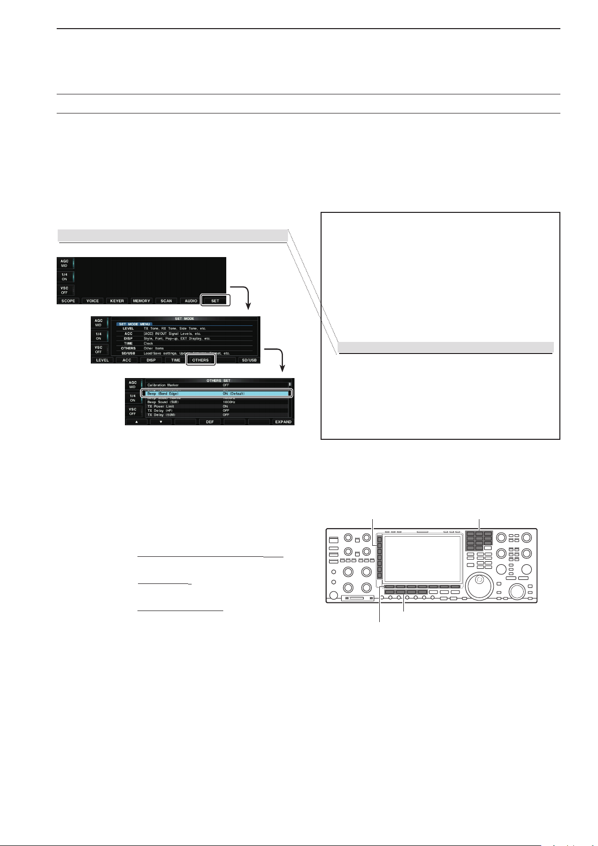
Routes to the Set Mode, setting screen and the setting items are described in the following manner.
Band edge warning beep
SET [F-7] OTHERS [F-5] Beep (Band Edge)
The normal screen
The SET MODE screen
The OTHERS SET screen
This function allows you to hear a beep tone when
you tune in or out of an amateur band’s frequency
range. A regular beep sounds when you tune into a
range, and a lower tone error beep will sound when
you tune out of a range.
Select the “Beep (Band Edge)” item in the Oth- q
ers set screen.
SET [F-7] OTHERS [F-5] Beep (Band Edge)
Rotate [MAIN DIAL] to select the option. w
• Band Edge Beep options:
OFF: Band edge beep is OFF.
ON (Default): When you tune into or out of the de-
fault amateur band’s frequency range,
a beep sounds. (default)
About the transceiver’s illustrations
To indicate the keys and knobs in the operating steps, the transceiver is illustrated as illustrated below.
Also, the keys and knobs are described in the following
manner.
() Multi-function keys
Example:
(F) Function key
Example: Push [SCOPE](F).
Mode key
Example: P
About the LCD monitor display
Due to the printing matter, the Display type differs from the defaults setting.
Push the Multi-function [METER]() key.
ush the Mode key [SSB].
() Multi-functionkeys Band key
Mode keys
(F) Function keys
vi
Page 8
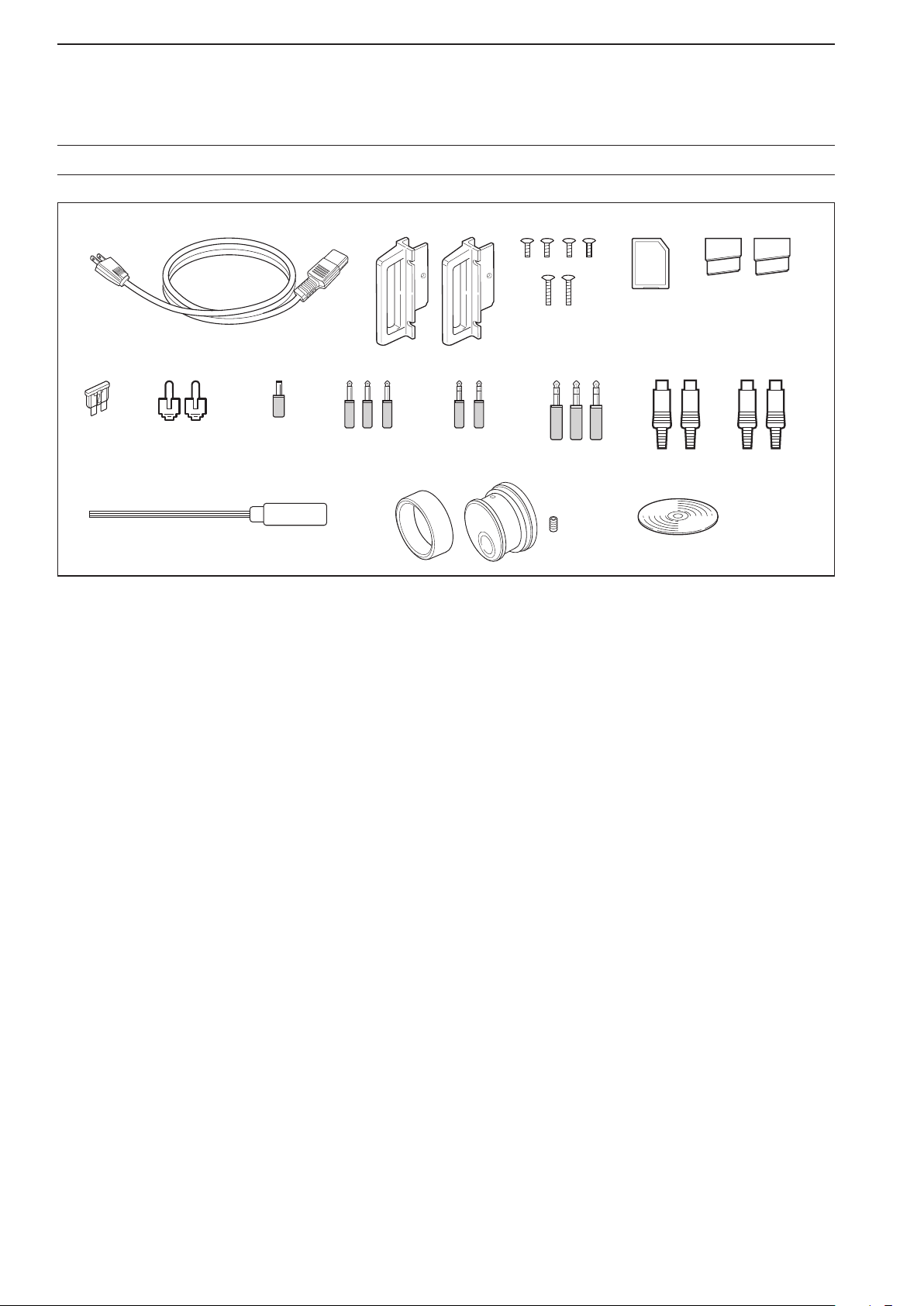
SUPPLIED ACCESSORIES
q
!0 !1 !2 !3
!4 !6!5
yu io
w
er t
Previous viewPrevious view
AC power cable q
†
.................................................. 1
Rack mounting handles w ................................ 1 pair
Screws for rack mounting handles e ................... 1 set
SD card r ................................................................. 1
Feet t .............................................................. 1 pair
Spare fuse (2 A) y .................................................. 1
RCA plugs u ........................................................... 2
DC plug i ............................................................... 1
2-conductor o
1
⁄8″ plugs .......................................... 3
!0 3-conductor 1⁄8″ plugs .......................................... 2
!1 3-conductor 1⁄4″ plugs .......................................... 3
!2 ACC plugs (7-pin) ................................................ 2
!3 ACC plugs (8-pin) ................................................ 2
!4 Hexagonal wrench‡ .............................................. 1
!5 Main dial‡ ............................................................. 1
!6 CD ....................................................................... 1
†
May differ from that shown depending on the version.
‡
See page 3-3 for the main dial attachment details.
vii
Page 9

TABLE OF CONTENTS
Previous viewPrevious view
PANEL DESCRIPTION Section 1
F ront panel ……………………………………………………………… 1-2
R ear panel ……………………………………………………………… 1-12
D isplay …………………………………………………………………… 1-14
S creen menu arrangement …………………………………………… 1-16
SET MODE ITEMS Section 2
A bout the Setting screen configuration ……………………………… 2-2
S COPE SET …………………………………………………………… 2-3
V OICE SET ……………………………………………………………… 2-4
K EYER 001 ……………………………………………………………… 2-4
K EYER CW-KEY ……………………………………………………… 2-5
R TTY LOG SET ………………………………………………………… 2-5
R TTY DECODE SET …………………………………………………… 2-5
P SK LOG SET ………………………………………………………… 2-6
P SK DECODE SET …………………………………………………… 2-6
S CAN SET ……………………………………………………………… 2-6
A UDIO SCOPE SET …………………………………………………… 2-6
L EVEL SET ……………………………………………………………… 2-7
A CC SET ………………………………………………………………… 2-8
D ISPLAY SET …………………………………………………………… 2-10
T IME SET ……………………………………………………………… 2-11
O THERS SET ……………………………………………………………2-11
L OAD SET ……………………………………………………………… 2-16
S AVE SET ……………………………………………………………… 2-16
A NT TYPE ……………………………………………………………… 2-16
V OX ……………………………………………………………………… 2-17
N B …………………………………………………………………………2-17
F ILTER SHAPE SET …………………………………………………… 2-17
INSTALLATION AND CONNECTIONS Section 3
U npacking ……………………………………………………………… 3-2
S electing a location …………………………………………………… 3-2
G rounding ……………………………………………………………… 3-2
A ttaching the rack mounting handle ………………………………… 3-2
C onnecting antenna …………………………………………………… 3-3
R equired connections ………………………………………………… 3-4
D Front panel (Electronic keyer and microphone) ………………… 3-4
D Rear panel (Basic connection) …………………………………… 3-4
A dvanced connections ………………………………………………… 3-5
D Front panel (Microphone, headphones and SD card) …………… 3-5
D Rear panel (Optional products and external equipment) ……… 3-5
D Rear panel (Optional products and external equipment) ……… 3-6
D Rear panel (External keypad and meter) ………………………… 3-6
L inear amplifier connections ………………………………………… 3-7
D Connecting the IC-PW1/EURO …………………………………… 3-7
D Connecting a non-Icom linear amplifier …………………………… 3-7
T ransverter jack information …………………………………………… 3-8
F SK and AFSK (SSTV) connections ………………………………… 3-8
M icrophones (optional products) ……………………………………… 3-9
viii
Page 10

TABLE OF CONTENTS
Previous viewPrevious view
D SM-50 ………………………………………………………………… 3-9
D SM-30 ………………………………………………………………… 3-9
D HM-36 ………………………………………………………………… 3-10
BASIC OPERATION Section 4
W hen first applying power …………………………………………… 4-2
P ower ON ……………………………………………………………… 4-3
R D esetting the CPU (initial setup) …………………………………… 4-3
A djusting the Volume level …………………………………………… 4-4
A djusting the Squelch level …………………………………………… 4-4
A djusting the RF gain ………………………………………………… 4-4
S electing Main and Sub bands ……………………………………… 4-5
S electing the VFO or memory mode ………………………………… 4-5
S electing an operating band…………………………………………… 4-6
U D sing the band stacking registers ………………………………… 4-6
S etting the frequency ………………………………………………… 4-7
T D uning with [DIAL] …………………………………………………… 4-7
A D bout the Quick tuning step ………………………………………… 4-7
S D electing the Fine tuning function ………………………………… 4-8
A D bout the Auto tuning step function ……………………………… 4-8
A D bout the 1⁄4 tuning step function ………………………………… 4-9
E D ntering the frequency with the keypad …………………………… 4-9
O perating mode selection ………………………………………………4-10
S electing the Meter readout …………………………………………… 4-11
D D igital multi-function meter ………………………………………… 4-11
S D electing the meter type …………………………………………… 4-12
D ial lock function ……………………………………………………… 4-12
B asic transmit operation ……………………………………………… 4-13
T D ransmitting ………………………………………………………… 4-13
A D djusting the microphone gain …………………………………… 4-13
D D rive gain adjustment ……………………………………………… 4-14
T D ransmit power limit …………………………………………………4-14
B and edge warning beep ……………………………………………… 4-15
E D ntering the user band edge ……………………………………… 4-16
A bout the 5 MHz frequency band operation (USA version only) …4-18
RECEIVE AND TRANSMIT Section 5
C onvenient functions for Receive …………………………………… 5-2
C onvenient functions for Transmit …………………………………… 5-3
O perating SSB ………………………………………………………… 5-4
O perating CW …………………………………………………………… 5-5
A D bout the CW pitch control ………………………………………… 5-6
A D PF (Audio Peak Filter) operation ………………………………… 5-6
A D djusting the Key speed …………………………………………… 5-7
A D bout the CW reverse mode ……………………………………… 5-7
C D W side tone function ……………………………………………… 5-7
A D bout 137 kHz band operation (Europe version only) ………… 5-8
E lectronic keyer functions ……………………………………………… 5-9
M D emory keyer screen ……………………………………………… 5-10
E D diting a Keyer memory …………………………………………… 5-11
ix
Page 11

TABLE OF CONTENTS
Previous viewPrevious view
C D ontest number set mode ………………………………………… 5-12
K D eyer set mode ……………………………………………………… 5-13
O perating RTTY (FSK) ………………………………………………… 5-14
A D bout the RTTY reverse mode …………………………………… 5-15
T D win peak filter ……………………………………………………… 5-15
F D unctions for the RTTY decoder display ………………………… 5-16
S D etting the decoder threshold level ………………………………… 5-17
R D TTY memory transmission ……………………………………… 5-17
A D utomatic transmission/reception setting ………………………… 5-18
E D diting the RTTY memory ………………………………………… 5-19
T D urning ON the RTTY log …………………………………………… 5-20
C D onfirm the RTTY log contents …………………………………… 5-21
R D TTY decode set mode …………………………………………… 5-22
O perating PSK ………………………………………………………… 5-24
V D ector indicator and Waterfall display ……………………………… 5-25
F D unctions for the PSK decoder display …………………………… 5-26
A D bout the BPSK and QPSK modes ……………………………… 5-27
A D bout the BPSK31 and BPSK63 modes ………………………… 5-27
S D etting the decoder threshold level ………………………………… 5-28
A D bout the PSK reverse mode ……………………………………… 5-28
A D FC/NET function …………………………………………………… 5-28
P D SK memory transmission ………………………………………… 5-29
A D utomatic transmission/reception setting ………………………… 5-30
E D diting the PSK memory …………………………………………… 5-31
T D urning ON the PSK log …………………………………………… 5-32
C D onfirm the PSK log contents ……………………………………… 5-33
P D SK decode set mode ……………………………………………… 5-34
O perating AM or FM …………………………………………………… 5-36
R epeater operation …………………………………………………… 5-37
C D hecking the repeater input signal ………………………………… 5-37
R D epeater tone frequency setting …………………………………… 5-38
T one squelch operation ………………………………………………… 5-39
D ata mode (AFSK) operation ………………………………………… 5-40
SCOPE OPERATION Section 6
S pectrum scope screen ……………………………………………… 6-2
O D perating the Spectrum scope …………………………………… 6-3
C D enter mode ………………………………………………………… 6-4
F D ixed mode …………………………………………………………… 6-5
D D ual scope screen …………………………………………………… 6-6
M D ini scope screen …………………………………………………… 6-6
S D cope attenuator …………………………………………………… 6-7
A D djusting the Reference level ……………………………………… 6-8
S D weep speed ………………………………………………………… 6-9
S D cope set screen …………………………………………………… 6-10
U D SB mouse operation ……………………………………………… 6-14
A udio scope screen …………………………………………………… 6-15
A D udio scope set mode ……………………………………………… 6-16
x
Page 12

TABLE OF CONTENTS
Previous viewPrevious view
Functions for Receive Section 7
P reamplifier ……………………………………………………………… 7-2
A ttenuator ……………………………………………………………… 7-2
R IT function ……………………………………………………………… 7-3
ï RIT monitor function ………………………………………………… 7-3
A GC function control …………………………………………………… 7-4
ï Selecting the preset value ………………………………………… 7-4
ï Adjusting the AGC time constant ………………………………… 7-4
ï Setting the AGC time constant preset value ……………………… 7-4
T win PBT operation …………………………………………………… 7-5
I F filter selection ………………………………………………………… 7-6
ï IF filter selection ……………………………………………………… 7-6
ï DSP filter shape ……………………………………………………… 7-7
ï Roofing filter selection ……………………………………………… 7-7
ï 1.2 kHz Filter calibration …………………………………………… 7-8
ï Filter shape set mode ……………………………………………… 7-9
D ualwatch operation …………………………………………………… 7-10
N oise blanker …………………………………………………………… 7-11
ï NB Set mode ………………………………………………………… 7-11
N oise reduction ………………………………………………………… 7-12
D igital selector ………………………………………………………… 7-12
N otch function ……………………………………………………………7-13
ï Auto notch function ………………………………………………… 7-13
ï Manual notch function ……………………………………………… 7-13
FUNCTIONS FOR TRANSMIT Section 8
About the VOX function ………………………………………………… 8-2
Turning ON D the VOX function ……………………………………… 8-2
A D djusting the VOX function ………………………………………… 8-2
V D OX set mode ……………………………………………………… 8-3
About the Break-in function …………………………………………… 8-4
S D emi break-in operation …………………………………………… 8-4
F D ull break-in operation ……………………………………………… 8-4
About the ⊿TX function ……………………………………………… 8-5
⊿ D TX monitor function ……………………………………………… 8-5
About the Monitor function …………………………………………… 8-5
Setting the Speech compressor (SSB only) ………………………… 8-6
Setting the Transmit filter width (SSB only) ………………………… 8-6
Operating the Split frequency ………………………………………… 8-7
About the Quick split function ………………………………………… 8-8
S D plit lock function …………………………………………………… 8-8
VOICE RECORDER FUNCTIONS Section 9
R ecording function ……………………………………………………… 9-2
R ecording a QSO ……………………………………………………… 9-3
ï Quick recording ……………………………………………………… 9-3
ï Basic recording ……………………………………………………… 9-3
P laying back the recorded audio (QSO) ……………………………… 9-4
O perating while playing back ………………………………………… 9-5
D eleting recorded audio file …………………………………………… 9-6
xi
Page 13

TABLE OF CONTENTS
Previous viewPrevious view
D eleting recorded audio folder ………………………………………… 9-6
R X Voice Memory ……………………………………………………… 9-7
R ecording the RX Voice Memory …………………………………… 9-8
P laying back the recorded audio ……………………………………… 9-8
ï Quick playing back ………………………………………………… 9-8
R ecording or playing back a TX message …………………………… 9-9
ï Recording …………………………………………………………… 9-9
ï Playing back ………………………………………………………… 9-9
ï Programming a record name ……………………………………… 9-10
T ransmitting a recorded message …………………………………… 9-11
ï Single TX …………………………………………………………… 9-11
ï Repeat TX …………………………………………………………… 9-11
ï Setting the transmit level …………………………………………… 9-12
V oice Set mode ………………………………………………………… 9-13
S aving a voice memory onto an SD card or USB flash drive ……… 9-14
USING AN SD CARD OR USB MEMORY Section 10
A bout the SD card ……………………………………………………… 10-2
ï Inserting the SD card ……………………………………………… 10-2
ï Removing the SD card ……………………………………………… 10-2
S aving the setting data onto an SD card or USB flash drive ……… 10-3
L oading the saved data files onto an SD card or USB flash drive … 10-4
S aving with a different file name ……………………………………… 10-5
D eleting a data file ……………………………………………………… 10-6
F ormatting an SD card or USB flash drive …………………………… 10-6
U nmounting an SD card or USB flash drive ………………………… 10-7
“ SD/USB-MEMORY SET” screen …………………………………… 10-8
ï “LOAD SET” screen ………………………………………………… 10-9
ï “SAVE SET” screen ……………………………………………… 10-10
MEMORY OPERATION Section 11
M emory channels ……………………………………………………… 11-2
M emory channel selection …………………………………………… 11-2
U D sing the M-CH [p] or [q] keys …………………………………… 11-2
U D sing the keypad …………………………………………………… 11-2
M emory list screen ……………………………………………………… 11-3
S D electing a memory channel using the Memory List screen …… 11-3
C D onfirming programmed memory channels ……………………… 11-3
Entering Memory channel contents ………………………………… 11-4
Entering D in the VFO mode ………………………………………… 11-4
Entering D in the Memory mode ………………………………………11-4
C opying Memory contents …………………………………………… 11-5
C D opying in the VFO mode ………………………………………… 11-5
C D opying in the Memory mode ……………………………………… 11-5
M emory names ………………………………………………………… 11-6
E D diting (programming) memory names …………………………… 11-6
M emory clearing………………………………………………………… 11-6
M emo pads ……………………………………………………………… 11-7
E D ntering frequencies and operating modes into Memo pads …… 11-7
C D alling up a frequency and operating mode from Memo pads …11-8
U D sing the Memo pad list screen …………………………………… 11-8
xii
Page 14

TABLE OF CONTENTS
Previous viewPrevious view
SCANS Section 12
S can types ……………………………………………………………… 12-2
P reparation ……………………………………………………………… 12-3
S can set mode ………………………………………………………… 12-4
P rogrammed scan ……………………………………………………… 12-5
F ine programmed scan ………………………………………………… 12-6
M emory scan operation ……………………………………………… 12-7
S elect memory scan operation ……………………………………… 12-7
S etting select memory channels ………………………………………12-8
S D etting in the Scan screen ………………………………………… 12-8
S D etting in the Memory list screen ………………………………… 12-8
E D rasing the select scan setting …………………………………… 12-8
⊿ F scan operation……………………………………………………… 12-9
F ine ⊿F scan …………………………………………………………… 12-9
T one scan …………………………………………………………… 12-10
V oice squelch control function ……………………………………… 12-10
ANTENNA TUNER OPERATION Section 13
A ntenna connection and selection …………………………………… 13-2
R eceive Antenna-I/O selection ……………………………………… 13-2
A ntenna memory settings ……………………………………………… 13-3
A D ntenna type selection ……………………………………………… 13-4
A D ntenna selection mode …………………………………………… 13-5
T D emporary memory ………………………………………………… 13-5
R D eceive antenna I/O setting ………………………………………… 13-6
A bout the Antenna tuner ……………………………………………… 13-7
U sing the Antenna tuner operation …………………………………… 13-7
I D f the tuner cannot tune the antenna ……………………………… 13-8
CLOCK AND TIMERS Section 14
T ime set mode ………………………………………………………… 14-2
S D etting the Date ……………………………………………………… 14-2
S D etting the Current time …………………………………………… 14-2
S D etting the UTC Offset ……………………………………………… 14-2
S D electing the CLOCK2 Function …………………………………… 14-3
S D etting the CLOCK2 UTC Offset …………………………………… 14-3
E D ntering the CLOCK2 Name ……………………………………… 14-3
S D etting the NTP Function …………………………………………… 14-4
S D etting the NTP Server address …………………………………… 14-4
S etting the Daily timer ………………………………………………… 14-5
S etting the Sleep timer ………………………………………………… 14-6
T imer operation ………………………………………………………… 14-6
SET MODE Section 15
Set mode description …………………………………………………… 15-2
D Set mode operation ………………………………………………… 15-2
D Screen arrangement …………………………………………………15-3
xiii
Page 15

TABLE OF CONTENTS
Previous viewPrevious view
Level Set mode ………………………………………………………… 15-4
ACC set mode ………………………………………………………… 15-6
Display set mode …………………………………………………… 15-10
Time set mode ……………………………………………………… 15-12
Others set mode ……………………………………………………… 15-13
MAINTENANCE Section 16
A djusting the Main dial brake ………………………………………… 16-2
U sing the Voice synthesizer operation ……………………………… 16-2
S WR reading …………………………………………………………… 16-3
C alibration the Frequency (approximate) …………………………… 16-4
S etting My call sign …………………………………………………… 16-5
C leaning ………………………………………………………………… 16-7
R esetting the CPU ……………………………………………………… 16-7
A bout protection indications …………………………………………… 16-8
O pening the transceiver’s case ……………………………………… 16-8
F use replacement ……………………………………………………… 16-9
C lock backup battery replacement …………………………………… 16-9
T roubleshooting ……………………………………………………… 16-10
D Transceiver power ………………………………………………… 16-10
D Transmit and receive ……………………………………………… 16-10
D Scanning …………………………………………………………… 16-11
D Display ……………………………………………………………… 16-11
UPDATING THE FIRMWARE Section 17
G eneral ………………………………………………………………… 17-2
D Checking the firmware version …………………………………… 17-2
P reparation ……………………………………………………………… 17-3
D File downloading …………………………………………………… 17-3
F irmware update— using an SD card/USB flash drive …………… 17-4
CONTROL COMMAND Section 18
Remote control (CI-V) information …………………………………… 18-2
CI-V connection D …………………………………………………… 18-2
Preparing D …………………………………………………………… 18-2
Data format D …………………………………………………………… 18-2
Data content description D ………………………………………… 18-10
SPECIFICATIONS AND OPTIONS Section 19
S pecifications …………………………………………………………… 19-2
D General ……………………………………………………………… 19-2
D Transmitter …………………………………………………………… 19-2
D Receiver ……………………………………………………………… 19-3
D Antenna tuner ………………………………………………………… 19-3
O ptions ………………………………………………………………… 19-4
xiv
Page 16

TABLE OF CONTENTS
Previous viewPrevious view
CONNECTOR INFORMATION Section 20
A CC socket ……………………………………………………………… 20-2
M icrophone connector ………………………………………………… 20-3
[ ELEC-KEY] jack ……………………………………………………… 20-3
[ KEY] jack ……………………………………………………………… 20-3
[ EXT KEYPAD] jack …………………………………………………… 20-4
[ REF I/O] connector …………………………………………………… 20-4
[ X-VERTER] connector ………………………………………………… 20-4
[ RELAY] jack …………………………………………………………… 20-4
[ METER] jack …………………………………………………………… 20-5
[ REMOTE] jack ………………………………………………………… 20-5
[ DC OUT] jack …………………………………………………………… 20-5
[ EXT-SP] jack …………………………………………………………… 20-5
[ S/P DIF] jack …………………………………………………………… 20-5
[ RX-I/O] connector ……………………………………………………… 20-5
INDEX
xv
Page 17

PANEL DESCRIPTION Section 1
Previous viewPrevious view
F ront panel ……………………………………………………………… 1-2
R ear panel ……………………………………………………………… 1-12
D isplay …………………………………………………………………… 1-14
S creen menu arrangement …………………………………………… 1-16
1-1
Page 18
1-2
1
PANEL DESCRIPTION
dash
dot
com
Previous viewPrevious view
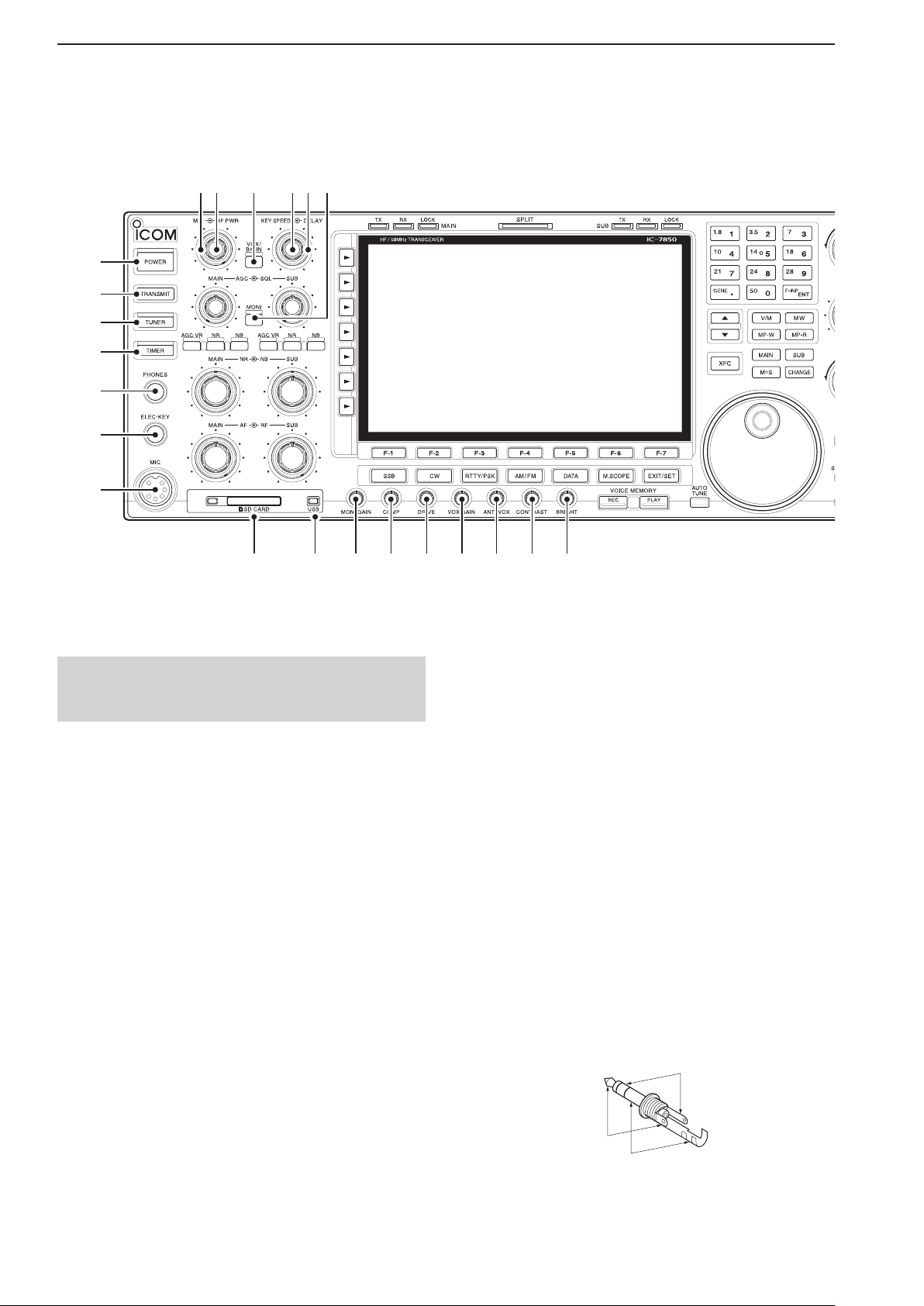
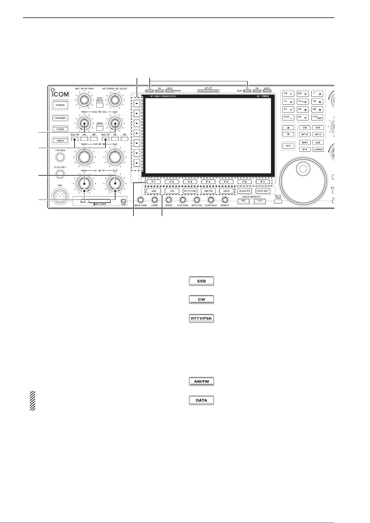
Front panel
q
w
e
r
t
y
u
@2
@1
@0
!9
!8
!7
i o !0 !1 !2 !3 !4 !5 !6
q POWER KEY [POWER] (pp. 4-3, 14-6)
First, turn ON the internal power supply. The internal
power supply switch is located on the rear panel.
(p. 1-12)
Push to turn ON the transceiver power.
• The [POWER] indicator above this key lights blue.
Hold down for 1 second to turn OFF the power.
• The [POWER] indicator lights orange when the transceiver is OFF, but the internal power supply is turned
ON.
w TRANSMIT KEY [TRANSMIT] (p. 4-13)
Push to transmit, release to receive.
• The [TX] indicator lights red while transmitting and the
[RX] indicator lights green when the squelch is open.
e ANTENNA TUNER KEY [TUNER] (p.13-7)
Momentarily push to turn the tuner ON or OFF
(bypass.)
• The [TUNER] indicator above this key lights white
when the tuner is turned ON, and goes off when the
tuner is turned OFF (bypassed).
Hold down for 1 second to manually start the
tuner.
•
The [TUNER] indicator blinks red during manual tuning.
• When the tuner cannot tune the antenna, the tuning
circuit is automatically bypassed after 20 seconds.
r TIMER KEY [TIMER] (p. 14-5)
Push to turn ON or OFF the sleep or daily timer
function.
• The [TIMER] indicator above this key lights white
when the timer is in use.
Hold down for 1 second to enter the Timer set
screen.
t HEADPHONE JACK [PHONES]
(p. 3-5)
Connect standard stereo headphones.
• Output power: 50 mW with an 8 Ω load.
• When headphones are connected, the internal speaker
and any connected external speaker do not function.
y
ELECTRONIC KEYER JACK [ELEC-KEY] (p. 20-3)
Connect a paddle to activate the internal electronic
keyer for CW operation.
• Select the internal electronic keyer, bug-key or straight
key operation in the Keyer set screen. (p. 5-13)
• A straight key jack is located on the rear panel. See
[KEY] on page 1-13.
• Set the keyer polarity (dot and dash) in the Keyer set
screen. (p. 5-13)
• Eight keyer memory channels can be used. (p. 5-11)
Page 19

1-3
1
PANEL DESCRIPTION
Previous viewPrevious view
u MICROPHONE CONNECTOR [MIC]
Connect an optional microphone.
• See page 3-4 for appropriate microphones.
• See page 20-3 for microphone connector information.
i SD CARD SLOT [SD CARD] (pp. 3-5, 10-2)
Insert the supplied SD card for both reading and storing a wide variety of the transceiver’s information and
data.
• The indicator beside the slot lights, or blinks when reading from or writing to the card.
• Push the card once to remove it.
o USB INDICATOR [USB]
(p. 10-4)
Lights while accessing a USB flash drive inserted to
the [USB A] port.
!0
MONITOR GAIN CONTROL [MONI GAIN] (p. 8-5)
Rotate to adjust the transmit IF signal monitor level.
!1 COMPRESSION LEVEL CONTROL [COMP]
(p. 8-6)
Rotate to adjust the speech compression level in
SSB.
!2 DRIVE GAIN CONTROL [DRIVE] (p. 4-14)
Rotate to adjust the transmitter level at the driver
stage. Activates in all modes
OFF)
.
(except SSB with [COMP]
!3 VOX GAIN CONTROL [VOX GAIN] (p. 8-2)
Rotate to adjust the transmit/receive switching
threshold level for VOX operation.
!9 ELECTRONIC CW KEYER SPEED CONTROL
[KEY SPEED] (p. 5-7)
Rotate to adjust the internal electronic CW keyer’s
speed to between 6 wpm (minimum) and 48 wpm
(maximum).
• The keyer’s speed is displayed.
@0 VOX/BREAK-IN KEY [VOX/BK-IN]
Push to turn the VOX function ON or OFF in the
SSB, AM, or FM mode. (p. 8-2)
Push to turn the break-in function ON (Semi break-
in, Full break-in)
or OFF in the CW mode. (p. 8-4)
Hold down for 1 second to enter the VOX set
screen. (p. 8-3)
What is the VOX function?
The VOX function (voice operated transmission) starts
transmission without pushing the transmit key or PTT
switch when you speak into the microphone, then automatically returns to receive when you stop speaking.
What is the break-in function?
The break-in function toggles between transmit and
receive with CW keying. Full break-in (QSK) can monitor the receive signal during keying.
@1 RF POWER CONTROL [RF PWR] (p. 4-13)
Rotate to continuously vary the RF output power
from less than 5 watts (minimum) to 200* watts
(maximum).
*AM mode: less than 5 W to 50 W
• The output power setting is displayed.
!4 ANTI VOX CONTROL [ANTI VOX] (p. 8-2)
Adjusts the VOX deactivate level to prevent un-
wanted VOX activation from the speaker or other
sounds.
!5 DISPLAY CONTRAST CONTROL [CONTRAST]
Adjusts the display contrast.
!6 DISPLAY BRIGHTNESS CONTROL [BRIGHT]
Adjusts the display brightness.
!7 MONITOR KEY [MONI] (p. 8-5)
Push to monitor your transmitted signal.
• The CW sidetone functions regardless of the [MONI] key
setting in the CW mode.
• The [MONI] indicator above this key lights white while
the function is activated.
!8 BREAK-IN DELAY CONTROL [DELAY] (p. 8-4)
Rotate to adjust the transmit-to-receive switching
delay time in the CW semi-break-in mode.
@2 MIC GAIN CONTROL [MIC]
Rotate to adjust microphone gain.
• The transmit audio tone in the SSB, AM, or FM mode
can be independently adjusted in the Level set screen.
(p. 4-13)
How to set the microphone gain.
Adjust the [MIC] control so that the ALC meter swings
within the ALC range during normal voice level transmission in the SSB or AM mode. (The ALC meter must
be selected.)
Page 20
1-4
1
PANEL DESCRIPTION
Previous viewPrevious view
Front panel (Continued)
@9#0
@3
@4
@5
@6
@7
@8
@3 AGC CONTROL [AGC] (p. 7-4)
Rotate to adjust the continuously-variable AGC cir-
cuit time constant.
• To use the [AGC] control, push the appropriate band’s
[AGC VR] (The [AGC VR] indicator lights white).
@4 AGC VOLUME KEY [AGC VR] (p. 7-4)
Push to toggle the [AGC] control ON or OFF.
• Use the [AGC] control to set the AGC time constant
when switched ON.
• The [AGC VR] indicator above this key lights white
when the control is ON.
Hold down for 1 second to turn OFF the AGC
function.
@5 AF CONTROL [AF] (p. 4-4)
Rotate to adjust the audio output level of the speak-
er or headphones.
@6 RF GAIN CONTROL [RF] (p. 4-4)
Rotate to adjust the RF gain level.
While rotating the RF gain control, you may hear
noise. This comes from the DSP unit and does
not indicate a malfunction.
@7 FUNCTION KEYS [F-1]–[F-7]
Push to select the function indicated in the display
above these keys.
• Functions vary, depending on the operating mode.
@8 MODE KEYS
Selects the desired mode. (p. 4-10)
•
The Voice synthesizer announces the selected mode.
(p. 16-2)
Push to alternately
select the USB or
LSB mode.
Push to alternately select the CW or
CW-R (CW reverse) mode.
Push to toggle between the RTTY and
PSK modes.
Hold down for 1 second to toggle be-
tween the RTTY and RTTY-R (RTTY re-
verse)
modes.
Hold down for 1 second to toggle be-
tween the PSK and PSK-R (PSK reverse)
modes.
Push to alternately
select the
AM or FM
mode.
Push to toggle between
the
SSB, AM, or
FM data (USB-D, LSB-D, AM-D, FM-D) and
voice modes.
Hold down for 1 second to toggle be-
tween D1, D2, and D3.
@9 TRANSMIT INDICATOR [TX]
Lights red while transmitting.
• The SUB band’s [TX] indicator lights only when in split
operation.
Page 21
1-5
1
PANEL DESCRIPTION
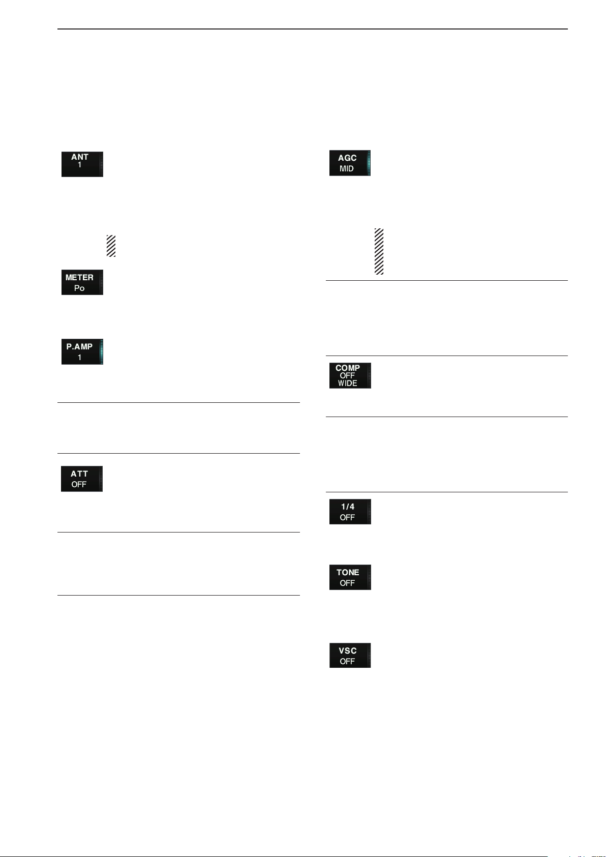
#0 MULTI-FUNCTION KEYS
Previous viewPrevious view
Push to select the functions indicated in the display
to the right of these keys.
• Functions vary, depending on the operating mode.
Push to select the ANT1, ANT2, ANT3 or
ANT4 antenna connector. (p. 13-2)
Hold down for 1 second to display the
antenna selection memory. (p.13-5)
• When the receive antenna is activated, the
antenna that is connected to [ANT4] is used
only for receive.
When a transverter is used, this [ANT]
does not function and “TRV” appears.
Push to select the RF power (Po), SWR,
ALC, COMP, Vd or Id metering while
transmitting. (p. 4-11)
Hold down for 1 second to turn the Digital
multi-function meter ON or OFF. (p. 4-11)
Push to select one of two receive RF
preamps, or bypass them. (p. 7-2)
• “P.AMP1” activates a 10 dB preamp.
• “P.AMP2” activates a 16 dB high-gain pre-
amp.
What is a preamp?
A preamp amplifies received signals in the front end
circuit to improve S/N ratio and sensitivity. Select
“P.AMP1” or “P.AMP2” when receiving weak signals.
Push to select the 6 dB, 12 dB or 18 dB
attenuator. (p. 7-2)
Hold down for 1 second to select the 3
dB, 6 dB, 9 dB, 12 dB, 18 dB, or 21 dB
attenuator. (p. 7-2)
What is an attenuator?
An attenuator prevents a desired signal from distorting
when very strong signals are near the desired frequency, or when very strong electric fields, such as from a
broadcasting station, are near your location.
Push to activate and then select the
“FAST,” “MID,” or “SLOW” AGC time constant. (p. 7-4)
• In the FM mode, only “FAST” is selectable.
Hold down for 1 second to enter the AGC
set mode. (p. 7-4)
The AGC time constant can be set be-
tween 0.1 to 8.0 second (depending on the
mode)
, or turned OFF. When AGC is
“OFF,” the S-meter does not function.
What is AGC?
The AGC controls receiver gain to produce a constant
audio output level, even when the received signal
strength varies dramatically. Select “FAST” for tuning
and then select “MID” or “SLOW” depending on the receiving condition.
Turns the speech compressor ON or
OFF in the SSB mode. (p. 8-6)
Selects the narrow, middle or wide com-
pression when held down for 1 second.
What is a speech compressor?
A speech compressor compresses the transmitter audio input to increase the average audio output level,
and therefore increase the talk power. This function
is effective for long-distance communication, or when
propagation conditions are poor.
Push to turn the 1⁄4-speed tuning func-
tion ON or OFF in the SSB data, CW,
RTTY and PSK modes. (p. 4-9)
• 1⁄4 function sets the dial rotation to 1⁄4 of the
normal speed for fine tuning.
In the FM mode, push to toggle between
the tone encoder, tone squelch function
and no-tone operation. (p. 5-39)
In the FM mode, hold down for 1 second
to enter the Tone set mode. (pp. 5-38,
5-39)
Push to turn the Voice squelch control
function ON or OFF. This is useful for
scanning. (p. 12-10)
Page 22
1-6
1
PANEL DESCRIPTION
S-meter
squelch
Noise squelch
Squelch
is open.
Squelch
threshold
Previous viewPrevious view
Front panel (Continued)
#1
#2
#3
#4
#5
$8 $6 $3$9%0
$5 $4
#6 #7$7#8 $1#9 $0 $2
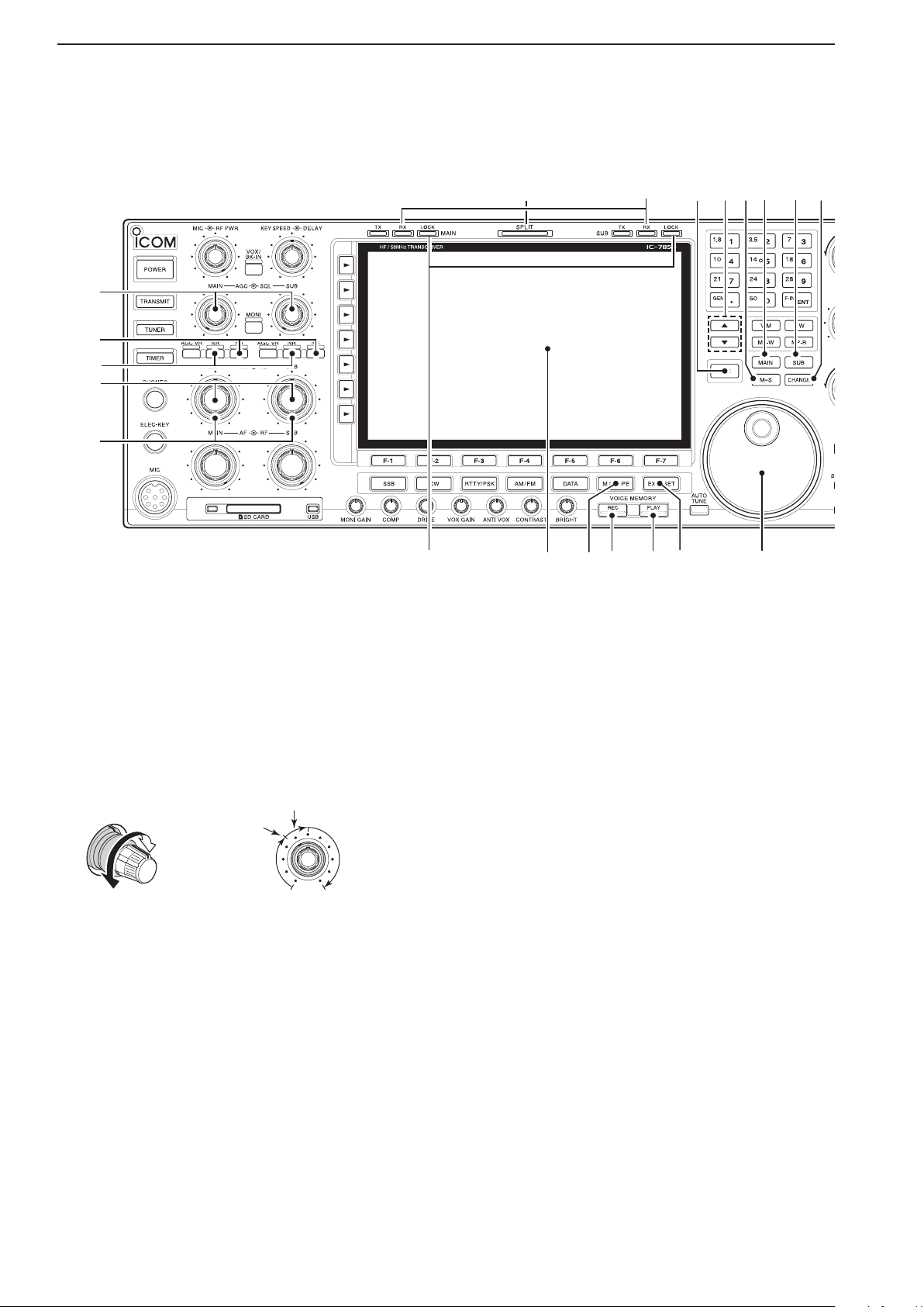
#1 SQUELCH CONTROL [SQL] (p. 4-4)
Rotate to adjust the squelch threshold level. The
squelch removes noise output from the speaker
(closed condition) when no signal is received.
• The squelch is particularly effective for FM. It is also
available for other modes.
• 11 to 12 o’clock position is recommended for any setting
of the [SQL] control.
#2 NOISE BLANKER KEY [NB] (p. 7-11)
Push to turn the noise blanker ON or OFF.
The noise blanker reduces pulse-type noise such
as that generated by automobile ignition systems.
This function cannot be used in the FM mode, or
for non-pulse-type noise.
• The [NB] indicator above this key lights white while
the function is activated.
Hold down for 1 second to enter the Noise blank-
er set mode.
#3
NOISE REDUCTION KEY [NR]
(p. 7-12)
Push to turn the DSP noise reduction ON or OFF.
• The [NR] indicator above this key lights white when the
function is activated.
#4 NOISE REDU
CTION LEVEL CONTROL [NR]
(p. 7-12)
Adjusts the DSP noise reduction level when the noise
reduction is in use. Set for maximum readability.
• To use this control, push the appropriate Main or Sub
band’s [NR].
#5 NOISE BLANKER CONTROL [NB] (p. 7-11)
Adjust the noise blanker threshold level.
• To use this control, push appropriate band’s [NB] key.
#6 LOCK INDICATOR [LOCK] (p. 4-12)
Lights when the dial lock function is activated.
#7 FUNCTION DISPLAY (p. 1-14)
Shows the operating frequency, function key menus,
Spectrum scope screen, Memory channel screen,
Page 23

1-7
1
PANEL DESCRIPTION
Previous viewPrevious view
Set mode settings, and so on.
#8
MINI SPECTRUM SCOPE KEY [M.SCOPE] (p. 6-2)
Push to t
urn the mini spectrum scope screen ON
or OFF.
• You can simultaneously display the mini spectrum
scope screen with other screens, such as the memory or set mode screens.
Hold down for 1 second to t
urn ON the regular
spectrum scope screen.
#9 VOICE MEMORY RECORD KEY [REC]
Push to store the previous received signal for the
preset time period. This function is called Instant
replay. (p. 9-7)
• The preset time period can be set in the Voice set
screen. (p. 9-13)
Hold down for 1 second to record a QSO (Communication) audio onto a memory device. (p. 9-3)
• Hold down again for 1 second to stop recording.
• The recorded memory device can be selected in the
Voice set screen. (p. 9-13)
$0 VOICE MEMORY PLAY BACK KEY [PLAY]
(pp. 9-2, 9-8)
Push to playback the last 5 seconds of the Instant
replay memory.
• The playback time can be changed in the Voice set
screen.
Hold down for 1 second to playback all of the in-
stant replay memory.
• The recording time can be changed in the Voice set
screen.
$1 EXIT/SET KEY [EXIT/SET]
Push to exit, or return to the previous screen in-
dication during Spectrum scope, Memory, Scan
or Set screen display.
Hold down for 1 second to display the Set mode
screen. (p. 15-3)
$4 SUB BAND ACCESS KEY [SUB]
Push to select the Sub band readout.
• The Sub band readout frequency is clearly displayed.
$5 MAIN BAND ACCESS KEY [MAIN]
Push to select the Main band readout.
• The Main band readout frequency is clearly displayed.
The Sub band readout functions only during split operation or Dualwatch.
$6 MAIN/SUB EQUALIZING KEY [M=S] (p. 8-7)
Hold down for 1 second to equalize the Sub band
readout frequency to the Main band readout frequency.
$7 MEMORY CHANNEL UP/DOWN KEYS [p]/[q]
(p. 11-2)
Push to select the desired memory channel.
• Memory channels can be selected both in the VFO and
the memory modes.
$8 TRANSMIT FREQUENCY CHECK KEY [XFC]
(p. 6-5)
Hold down to monitor the transmit frequency (includ-
ing ∂TX frequency offset)
during split frequency op-
eration.
• While holding down, the transmit frequency can be
changed with [MAIN DIAL], keypad, memo pad or [Y]/
[Z] keys.
• When the split lock function is turned ON, push [XFC] to
cancel the Dial lock function. (pp. 8-7, 8-8)
$9 RECEIVE INDICATOR [RX]
Lights green while receiving a signal and when the
squelch is open.
%0 SPLIT OPERATION INDICATOR [SPLIT] (p. 8-7)
Lights white during split frequency operation.
$2 MAIN DIAL
Changes the displayed frequency (Main band), se-
$3
Push to toggle the frequency and selected memory
• When the split frequency function is ON, push to toggle
lects set mode option, and so on.
MAIN/SUB CHANGE KEY [CHANGE] (pp. 7-10, 8-7)
channel between the Main and Sub band readouts.
between the transmit frequency and the receive frequency.
Page 24
1-8
1
PANEL DESCRIPTION
Previous viewPrevious view
Front panel (Continued)
^4%9^3 ^2
^1
^0
%1 %2
%8
%7
%6
%5
%4
%3
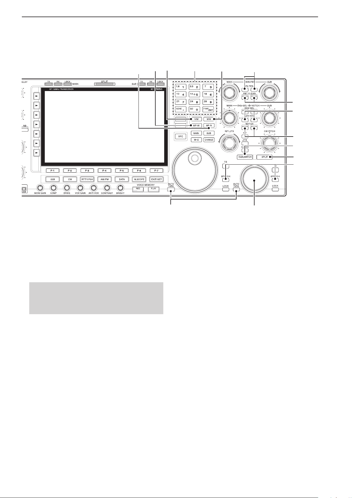
%1 AUTOMATIC TUNING KEY [AUTO TUNE]
Push to turn ON the Automatic tuning function in the
CW or AM mode.
IMPORTANT!
When receiving a weak signal, or receiving a signal
with interference, the automatic tuning function may
tune the receiver to an undesired signal.
%2 SUB DIAL
Changes the displayed frequency in the Sub band.
%3 SPEECH KEY [SPEECH] (p. 16-2)
Push to announce the S-meter level and the se-
lected operating frequency.
• You can change the speech language, speech speed,
and speech contents in the Others set screen.
(p. 15-14)
Hold down for 1 second to announce the select-
ed operating mode.
%4 SPLIT KEY [SPLIT] (pp. 8-7, 8-8)
Push to turn the split function ON or OFF.
Hold down for 1 second to turn the split func-
tion ON and equalize the Sub band frequency to
the Main band in non-FM modes, and then sets
the Sub band readout for frequency input mode.
(Quick split function)
• In the FM mode, the Sub band frequency is shifted
by the preset frequency offset from the Main band
readout frequency. (p. 15-14)
• The quick split function can be turned OFF in the Others set screen. (p. 15-13)
After entering a frequency offset, push to turn
ON the split function. The Sub band frequency
is shifted the offset amount from the Main band
frequency.
%5 DUALWATCH KEY [DUALWATCH] (p. 7-10)
Push to turn the Dualwatch function ON or OFF.
Hold down for 1 second to turn the Dualwatch
function ON, and equalize the Main/Sub band
frequency to the Sub/Main band. (Quick dualwatch function)
• The Quick Dualwatch function can be turned OFF in
the Others set screen. (p. 15-13)
Page 25

1-9
1
PANEL DESCRIPTION
AN
APF
TPF
Previous viewPrevious view
%6 NOTCH KEY [NOTCH]
(p. 7-13)
Push to select the Notch function between auto,
manual, or OFF in the SSB or AM mode.
Push to turn the Manual notch function ON or
OFF in the CW, RTTY, or PSK mode.
Push to turn the Auto notch function ON or OFF
in the FM mode.
• “MN” is displayed when the Manual notch filter is in
use.
• “
” is displayed when the Auto notch filter is in
use.
Hold down for 1 second to select the Manual
notch width from wide, mid, or narrow.
What is the Notch function?
The notch function eliminates unwanted CW or AM
carrier tones while preserving the desired voice signal.
The DSP circuit automatically adjusts the filtering frequency to effectively eliminate unwanted tones.
%7 AUDIO PEAK FILTER/TWIN PEAK FILTER KEY
[APF/TPF]
During CW mode operation (p. 5-6)
Push to turn the Audio peak filter ON or OFF.
• “
” appears when audio peak filter is in use.
Hold down for 1 second to select the APF pass-
band width from WIDE, MID, or NAR or from 320,
160, or 80 Hz, depending on the APF type setting.
During RTTY mode operation (p. 5-15)
Push to turn the Twin peak filter ON or OFF.
• “
” appears when twin peak filter is in use.
%8 PBT CLEAR KEY [PBT CLEAR] (p. 7-5)
Hold down for 1 second to clear the PBT settings.
• The [PBT CLEAR] indicator above this key lights when
the PBT function is in use.
%9 FILTER KEY [FILTER] (p. 7-6)
Push to select one of three IF filter settings.
Hold down for 1 second to enter the Filter
screen.
^0 MEMORY WRITE KEY [MW] (p. 11-4)
Hold down for 1 second to store the selected fre-
quency and operating mode into the displayed
memory channel.
• This function is usable in both the VFO and memory
modes.
^1 KEYPAD
Push to select the operating band.
• Push [GENE] to select the general coverage band.
Push the same key 2 or 3 times to call up other
stacked frequencies in the band. (p. 4-6)
• Icom’s triple band stacking register memorizes 3 frequencies in each band.
After pushing [F-INP], push to enter a frequency
or memory channel. Pushing [ENT] or [p]/[q] to
save and exit. (pp. 4-9, 11-2)
• Example: To enter 14.195 MHz, push [F-INP] [1] [4]
[•] [1] [9] [5] [ENT].
^2 VFO/MEMORY KEY [V/M]
Push to toggle the selected operating mode be-
tween the VFO and memory. (pp. 4-5, 11-2)
Hold down for 1 second to copy the memory con-
tents to the VFO. (p. 11-5)
^3 MEMO PAD-WRITE KEY [MP-W] (p. 11-7)
Enters the selected frequency and operating mode
into a memo pad.
• The ve most recent entries remain in the memo pads.
• The number of memo pads can be expanded from 5 to
10 in the Others set screen. (p. 15-15)
^4 MEMO PAD-READ KEY [MP-R] (p. 11-8)
Push to call up a frequency and operating mode
in a memo pad.
The 5 (or 10) most recently entered frequencies
and operating modes can be recalled, starting
from the most recent.
• The number of memo pads can be expanded from 5
to 10 in Others set screen. (p. 15-15)
Hold down for 1 second to enter the Memo pad
list screen.
Page 26
1-10
1
PANEL DESCRIPTION
Previous viewPrevious view
Front panel (Continued)
&5 &4
&3
&2
&1
&0
^9
^8
^7
^6
^5 LOCK KEY [LOCK] (p. 4-12)
Push to turn the Dial lock function ON or OFF.
^6 QUICK TUNING KEY [TS]
Push to turn the Quick Tuning step function ON or
OFF. (p. 4-7)
• While the Quick Tuning icon, “Z,” is displayed above
the frequency readout, the frequency can be changed
in selected kHz steps.
• 0.1, 1, 5, 9, 10, 12.5, 20 and 25 kHz steps can be
independently set for each operating mode.
When the Quick tuning step is OFF, hold down
for 1 second to turn the 1 Hz tuning step ON or
OFF. (p. 4-8)
When the Quick Tuning step is ON, hold down
for 1 second to enter the Quick Tuning step set
screen. (p. 4-7)
^7 CLEAR KEY [CLEAR] (pp. 7-3, 8-5)
You can clear the RIT/∂TX shift frequency by hold-
ing down for 1 second or pushing, depending on the
quick RIT/∂TX clear function setting (p. ?12-18).
^8 ∂TX KEY [∂TX] (p. 8-5)
Push to turn the ∂TX function ON or OFF.
• Rotate the [RIT/∂TX] control to vary the ∂TX fre-
quency.
Hold down for 1 second to add the ∂TX shift fre-
quency to the operating frequency.
What is the ∂TX function?
∂TX shifts the transmit frequency without shifting the
receive frequency. This is useful for simple split frequency operation in CW, and so on.
^5
^9 RIT KEY [RIT] (p. 7-3)
Push to turn the RIT function ON or OFF.
• Rotate the [RIT/∂TX] control to vary the RIT frequen-
cy.
Hold down for 1 second to add the RIT shift fre-
quency to the operating frequency.
What is the RIT function?
Receiver incremental tuning (RIT) shifts the receive
frequency without shifting the transmit frequency.
This is useful for fine tuning stations calling you on
off-frequency or when you prefer to listen to slightly
different-sounding voice characteristics, and so on.
&0 CW PITCH CONTROL [CW PITCH] (p. 5-6)
Shifts the received CW audio pitch and the CW side
tone pitch without changing the operating frequency.
&1 MANUAL NOTCH FILTER CONTROL [NOTCH]
(p. 7-13)
Varies the “valley” frequency of the manual notch
filter to reject an interfering signal while the manual
notch function is ON.
• Notch lter center frequency:
SSB : –1060 Hz ~ 4040 Hz
CW : CW pitch frequency + 2540 Hz ~ CW pitch
frequency –2540 Hz
AM : –5100 Hz ~ 5100 Hz
&2 DIGITAL RF SELECTOR CONTROL [DIGI-SEL]
(p. 7-12)
Adjusts the digital RF selector center frequency.
• The control can be reassigned as the Audio peak lter
adjustment (p. 15-15)
Page 27
1-11
1
PANEL DESCRIPTION
&3 DIGITAL RF SELECTOR KEY [DIGI-SEL]
PBT2
PBT1
Low cutHigh cut Center
–+
Previous viewPrevious view
(p. 7-12)
Push to turn the digital RF preselector ON or OFF.
• The [DIGI-SEL] indicator lights white when the preselector is in use.
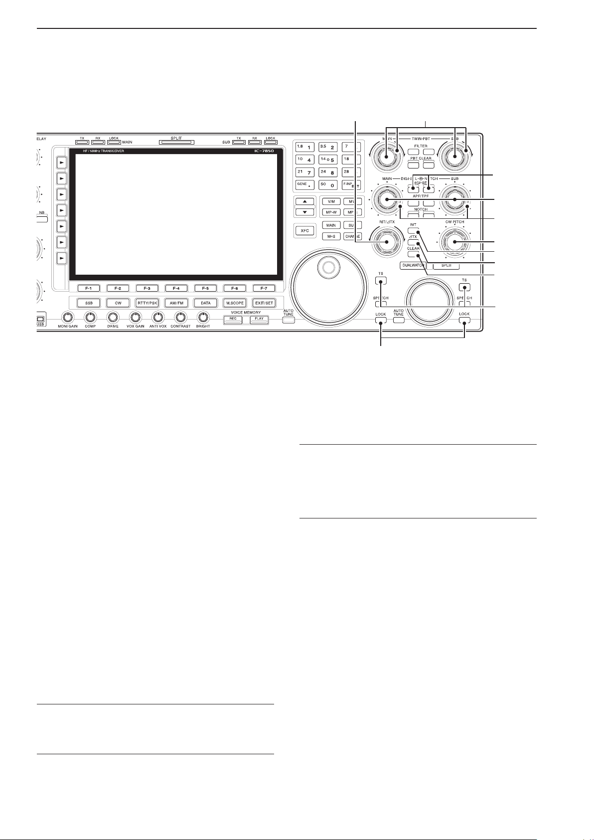
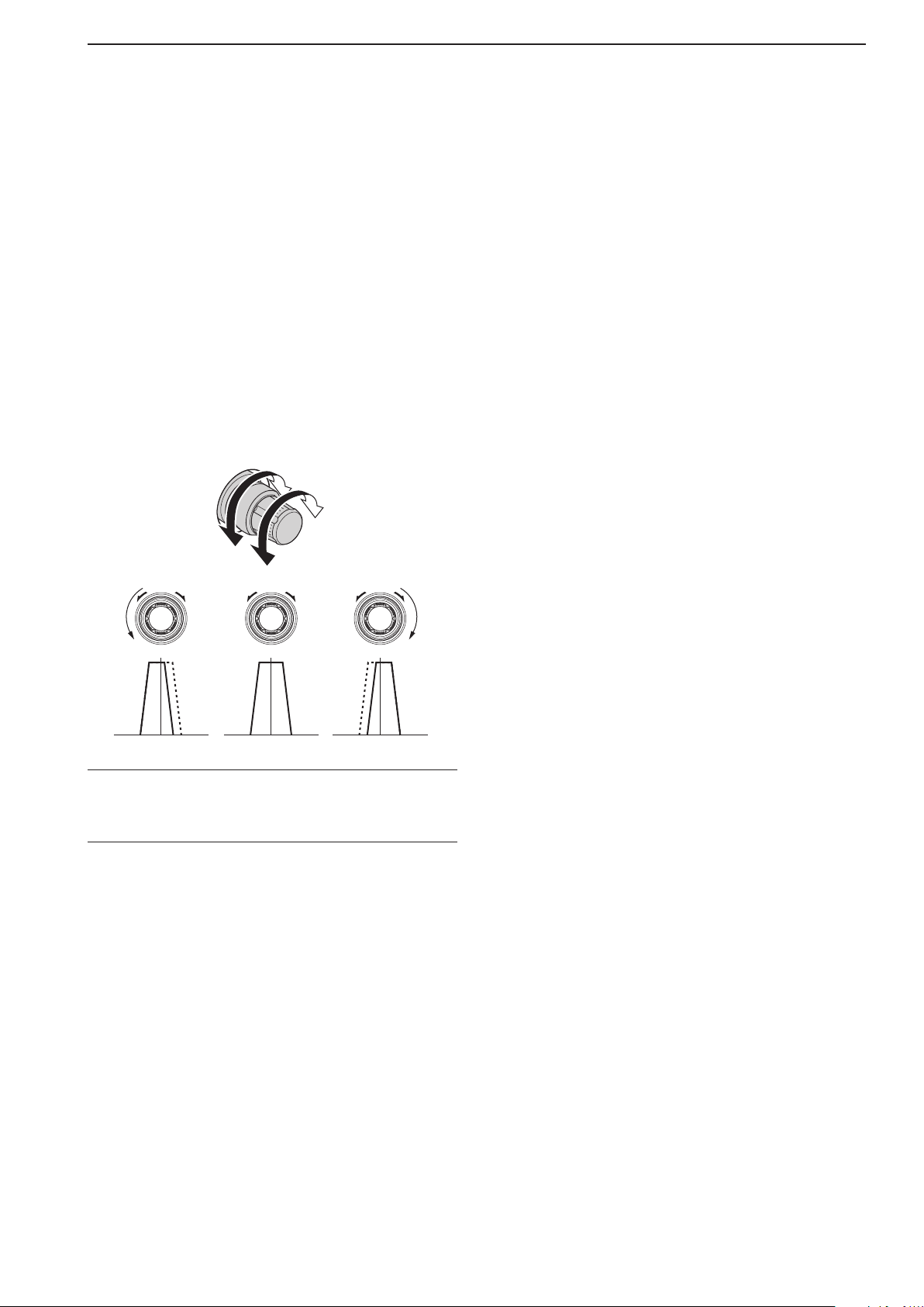
&4 PASSBAND TUNING CONTROLS [TWIN PBT]
(p. 7-5)
Adjusts the receiver’s IF filter “passband width” us-
ing the DSP.
• The passband width and shift frequency are displayed in
the Multi-function display.
•
Hold down [PBT CLEAR] for 1 second to clear the PBT
settings.
• The adjustment range is half of the selected lter passband width, and the value is adjustable in 25 Hz steps
for the SSB/CW/RTTY/PSK modes, and 100 Hz steps
for the AM mode.
What is the PBT control?
The PBT function electronically modifies the IF passband
width to reject interference. This transceiver uses the DSP
circuit for the PBT function.
&5 RIT/∂TX CONTROL [RIT/∂TX] (pp. 7-3, 8-5)
Shifts the receive and/or transmit frequency without
changing the transmit and/or receive frequency.
• Rotate the control clockwise to increase the frequency,
or rotate the control counterclockwise to decrease the
frequency. The RIT or ∂TX functions must be ON.
• The shift frequency range is ±9.999 kHz in 1 Hz steps (or
±9.99 kHz in 10 Hz steps).
Page 28
1-12
1
PANEL DESCRIPTION
L
B
q
!1!2!4 !3!5!6!7!8!9@0@1@2@3@4@5@6@7@8
r t y u i
o
!0
w e
Previous viewPrevious view
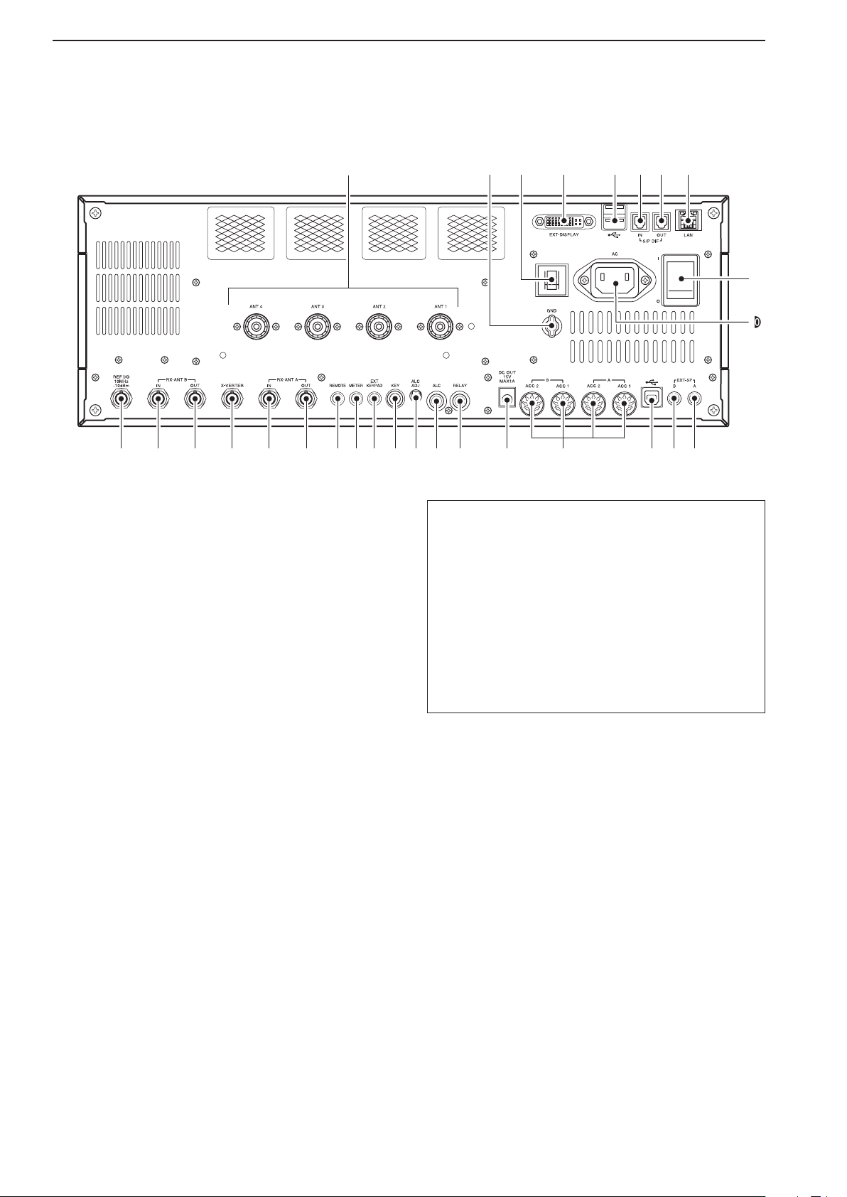
Rear panel
q ANTENNA CONNECTOR [ANT 1–4] (p. 3-4)
Connects to a 50 Ω antenna with a PL-259 plug
connector.
w GROUND TERMINAL [GND] (p. 3-2)
Connect this terminal to ground to prevent electrical
shocks, TVI, BCI and other problems.
e CIRCUIT BREAKER
Cuts off the AC input if excessive current flows.
r EXTERNAL DISPLAY TERMINAL [EXT-DISPLAY]
(p. 3-6)
Connects to an external display monitor.
• At least 800×600 pixel display is necessary.
t USB (Universal Serial Bus) PORT [USB A]
Insert a USB flash drive* for both reading and
storing a wide variety of the transceiver’s information and data.
• The indicator lights or blinks when the transceiver
reads or writes to the memory data.
• An unmount operation should be performed before
removing the USB flash drive*.
Connects to a PC keyboard for RTTY and PSK
operations.
• USB keyboards* are supported.
*: A USB flash drive or USB keyboard is not supplied
by Icom.
About the [USB A] connector:
• Supports only a USB ash drive, keyboard, mouse
or hub.
• Turn the transceiver power OFF when connecting
or disconnecting a USB keyboard, mouse or hub.
• DO NOT connect the following devices:
- Two or more of the same kind of USB devices.
(Example: Two USB hubs or two USB mice)
- A Multimedia adapter
- A USB HDD
- A USB flash drive larger than 32 GB
- A Bluetooth® keyboard or mouse.
y S/P DIF INPUT TERMINAL [S/P DIF– IN]
u S/P DIF OUTPUT TERMINAL [S/P DIF– OUT]
Connects to external equipment that supports S/P
DIF input/output.
i ETHERNET CONNECTOR [LAN] (p. 3-6)
Connects to a PC network through a LAN (Local
Area Network).
o MAIN POWER KEY [I/O] (p. 4-3)
Turns the internal power supply ON or OFF.
!0 AC POWER SOCKET [AC] (p. 3-4)
Connects the supplied AC power cable to an AC re-
ceptacle.
!1
EXTERNAL SPEAKER JACK MAIN [EXT-SP A]
(p. 3-5)
!2
EXTERNAL SPEAKER JACK SUB [EXT-SP B]
(p. 3-5)
Connects to an external speaker (4–8 Ω), if de-
sired.
Page 29
1-13
1
PANEL DESCRIPTION
+
_
_
+
_
Previous viewPrevious view
!3
USB PORT [USB B]
USB B type port connects to a PC.
• A USB A-USB B cable is required.
!4 ACCESSORY SOCKET [A ACC1]
ACCESSORY SOCKET [A ACC2]
ACCESSORY SOCKET [B ACC1]
ACCESSORY SOCKET [B ACC2]
Connects to external equipment such as a linear
amplifier, an automatic antenna selector/tuner, a
TNC for data communications, and so on.
• See page 20-2 for detailed socket information.
!5 DC OUTPUT JACK [DC OUT] (p. 20-5)
Outputs regulated 14 V DC (approximately) for external equipment. Connected in parallel with 13.8 V
outputs of [ACC 1] and [ACC 2]. (maximum 1 A in
total)
!6 T/R CONTROL JACK [RELAY] (pp. 3-5, 20-4)
Goes to ground when transmitting to control an ex-
ternal unit, such as a non-Icom linear amplifier.
NOTE: T/R control voltage and current must be
lower than 16 V DC/0.5 A (or 250 V AC,
200 mA with MOS-FET switching).
!7 ALC INPUT JACK [ALC] (p. 3-5)
Connects to the ALC output jack of a non-Icom lin-
ear amplifier.
!8 ALC LEVEL ADJUSTMENT POT [ALC ADJ]
Rotate to adjust the ALC levels.
No adjustment is required when the ALC output lev-
el of the connected non-Icom linear amplifier is 0 to
–4 V DC.
@1 METER JACK [METER] (p. 20-5)
Outputs the received signal strength, transmit out-
put power, VSWR, ALC, speech compression, V
d or
Id levels for an external meter.
@2 CI-V REMOTE CONTROL JACK [REMOTE]
(p. 20-5)
Connects to a PC through the optional CT-17
l e v e l c o n v e r t e r for external control of the trans-
c i -v
ceiver.
Used for transceive operation with another Icom
CI-V transceiver or receiver.
@3 RECEIVE ANTENNA A OUT [RX ANT A– OUT]
@4 RECEIVE ANTENNA A IN [RX ANT A– IN]
Located between the transmit/receive switching cir-
cuit and the receiver’s RF stage in the Sub band
(Main band in the split frequency mode).
Connects to an external unit, such as preamplifier
or RF filter, using BNC connectors, if desired.
When no external unit is connected, [RX ANT A–
IN] and [RX ANT A– OUT] must be deactivated
and internally shorted by the switching relay. This
setting is available in the Antenna screen. (p. 13-6)
@5 TRANSVERTER CONNECTOR [X-VERTER]
(p. 20-4)
Connects to an external transverter for input/out-
put.
Activated by a voltage applied to [ACC 2] pin 6, or
when the transverter function is in use. (pp. 20-2,
15-14)
@6 RECEIVE ANTENNA B OUT [RX ANT B– OUT]
@7 RECEIVE ANTENNA B IN [RX ANT B– IN]
Located between the transmit/receive switching cir-
cuit and receiver’s RF stage in the Main band (Sub
band during split operation).
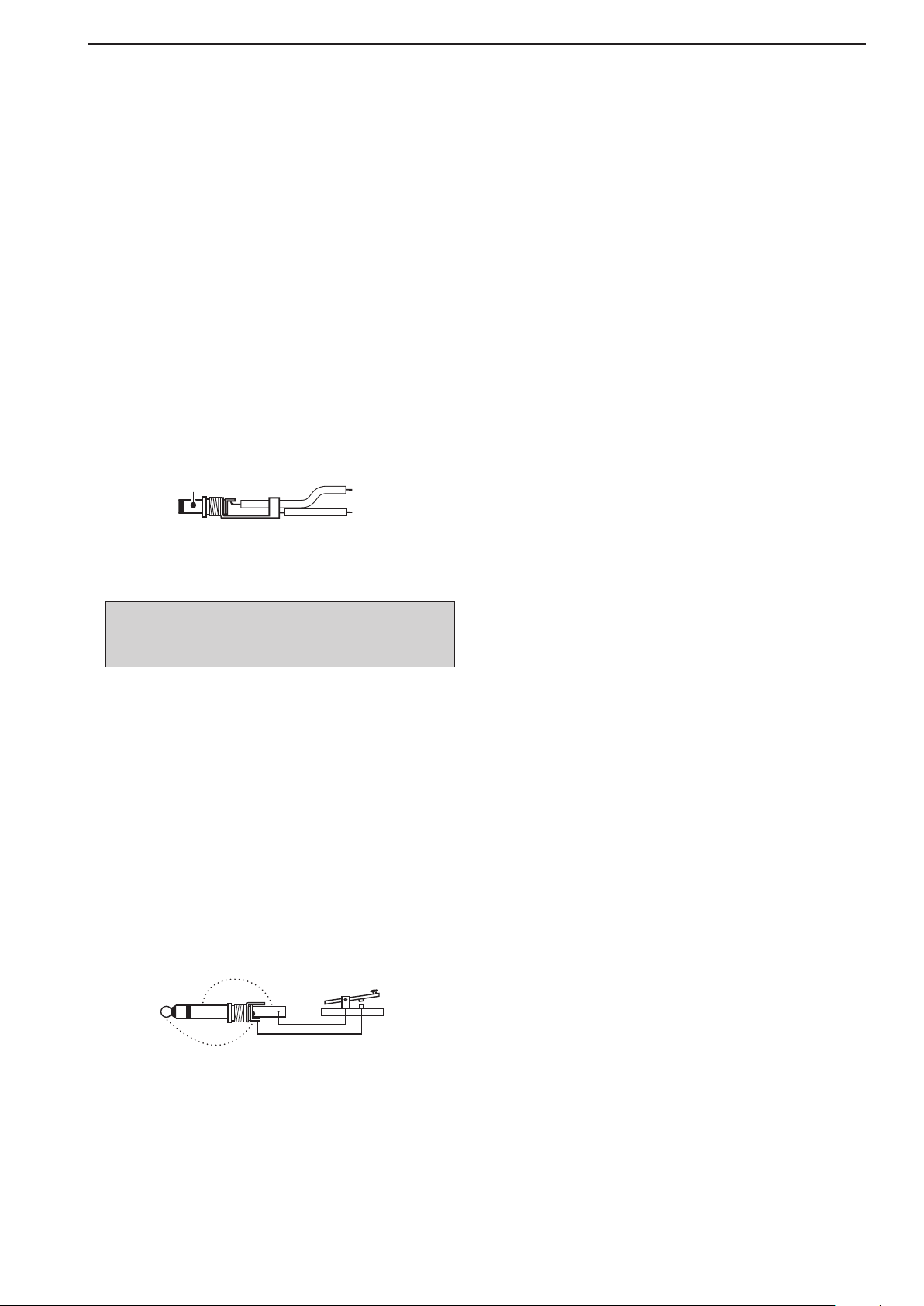
!9 STRAIGHT KEY JACK [KEY] (p. 20-3)
Connects to a straight key or external electronic
• [ELEC-KEY] on the front panel can be used for a straight
@0 EXTERNAL KEYPAD JACK [EXT KEYPAD]
Connects to an external keypad for direct voice
A transceiver mute control line (both transmit and
keyer with
key or external electronic keyer. Deactivate the internal
electronic keyer in the Keyer set screen. (p. 5-13)
1
⁄4 inch standard plug.
(p. 20-4)
memory (p. 9-11), memory keyer (p. 5-10), RTTY
memory (p. 5-17) or PSK memory (p. 5-29) trans-
mission.
receive) is also supported.
Connects an external unit, such as preamplifier or
RF filter, using BNC connectors, if desired.
When no external unit is connected, [RX ANT B–
IN] and [RX ANT B– OUT] must be deactivated
and internally shorted by the switching relay. This
setting is available in the Antenna screen. (p. 13-6)
@8 REFERENCE SIGNAL INPUT/OUTPUT
TERMINAL [REF I/O]
Input or output for a 10 MHz reference signal.
Page 30
1-14
1
PANEL DESCRIPTION
TX
TX
TX
Previous viewPrevious view
Display
!0
!3
!2
!1
o
e er ry yu uiq
qw wt
t
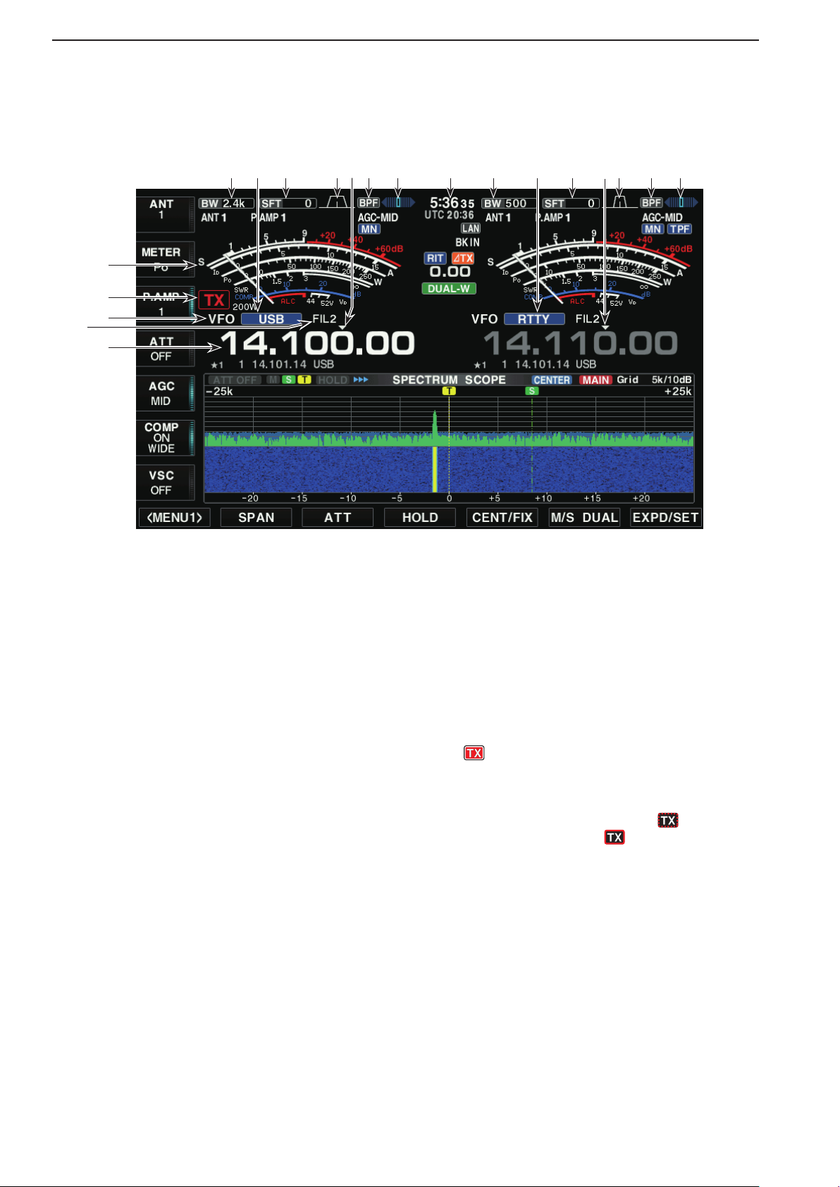
q BAND WIDTH INDICATOR (p. 7-5)
Displays the passband width of the IF filter.
w MODE INDICATOR
Displays the selected mode.
e SHIFT FREQUENCY INDICATOR (p. 7-5)
Displays the shift frequency of the IF filter.
r PASSBAND WIDTH INDICATOR (p. 7-5)
Graphically displays the passband width for twin
PBT operation and the center frequency for IF shift
operation.
t QUICK TUNING INDICATOR (p. 4-7)
Appears when the Quick Tuning step function is ON.
y BANDPASS FILTER INDICATOR
Appears when the narrow filter (500 Hz or less) is
selected in the CW, RTTY, or PSK mode.
u RTTY TUNING INDICATOR
Displays the tuning level in the RTTY mode.
i CLOCK READOUT
Displays the current time.
o FREQUENCY READOUTS
Displays the operating frequency.
• Gray characters are used for a non-active frequency.
!0 IF FILTER INDICATOR
Displays the selected IF filter number.
!1 VFO/MEMORY CHANNEL INDICATOR (p. 4-5)
Indicates the VFO mode or selected memory chan-
nel number.
!2 TX ICON
“
” appears while transmitting.
Indicates the frequency used for transmit.
• Displays on the Sub readout when the split function
is turned ON.
• A TX icon with doted rectangle, “
instead of the regular “
quency outside of an amateur band frequency range
is selected. This function can be turned OFF in the
Other set screen, if desired. (p. 4-5)
” TX icon, when a fre-
” is displayed,
!3 S/RF METER (p. 4-11)
Displays the signal strength while receiving. Dis-
plays the relative output power, SWR, ALC or compression levels while transmitting.
Page 31

1-15
1
PANEL DESCRIPTION
Previous viewPrevious view
Display (Continued)
!4
!9
!5
!8
!4 LAN INDICATOR
Displays when the Remote station accesses the
transceiver through the LAN connector. (An optional
RS-BA1 is required.)
!5 MULTI-FUNCTION SCREEN
Display screen for the Digital multi-function me-
ter, Spectrum scope, Audio scope, Voice recorder,
Memory channel, Scan, Memory keyer, RTTY decoder, PSK decoder, IF filter selection, and Set
modes.
!6 DISPLAY FUNCTION KEY GUIDE
Indicates the current function of the Display Func-
tion keys ([F-1] – [F-7]).
MEMORY CHANNEL READOUTS
!7
Displays the selected memory channel contents
in the VFO mode.
Displays the VFO contents in memory mode.
SELECT MEMORY CHANNEL INDICATOR
!8
(p. 12-7)
Indicates the displayed memory channel that is as-
signed as a Select memory channel.
The desired memory channels can be assigned to 3
select groups, for fast, convenient scanning.
!8!7 !7
!6
!9 MULTI-FUNCTION KEY GUIDE
Displays the function of the Multi-function keys.
Page 32

1
Previous viewPrevious view
PANEL DESCRIPTION
Screen menu arrangement
The following screens can be selected from the Start
Up screen. Choose the desired screen using the following guide.
• Start Up screen
F-1
• Spectrum scope screen (p. 6-2)
F-2
F-3 F-4 F-5 F-6 F-7
Pushing [EXIT/SET] several times returns to the Start
Up screen. See page 15-3 for set mode arrangement.
• PSK decode screen (p. 5-26)
F-3
• Memory channel screen (p. 11-3)
F-4
• Scan screen (VFO mode: p. 12-5)
F-5
• Voice recorder screen (p. 9-3)
F-2 F-5
• Memory keyer screen (CW mode: p. 5-10)
F-3
• RTTY decode screen (p. 5-16) • Set mode menu screen (p. 15-3)
• Scan screen (Memory mode: p. 12-7)
• Audio scope screen (p. 6-15)
F-6
F-3
F-7
1-16
Page 33

SET MODE ITEMS Section 2
Previous viewPrevious view
A bout the Setting screen configuration ……………………………… 2-2
S COPE SET …………………………………………………………… 2-3
V OICE SET ……………………………………………………………… 2-4
K EYER 001 ……………………………………………………………… 2-4
K EYER CW-KEY ……………………………………………………… 2-5
R TTY LOG SET ………………………………………………………… 2-5
R TTY DECODE SET …………………………………………………… 2-5
P SK LOG SET ………………………………………………………… 2-6
P SK DECODE SET …………………………………………………… 2-6
S CAN SET ……………………………………………………………… 2-6
A UDIO SCOPE SET …………………………………………………… 2-6
L EVEL SET ……………………………………………………………… 2-7
A CC SET ………………………………………………………………… 2-8
D ISPLAY SET …………………………………………………………… 2-10
T IME SET ……………………………………………………………… 2-11
O THERS SET ……………………………………………………………2-11
L OAD SET ……………………………………………………………… 2-16
S AVE SET ……………………………………………………………… 2-16
A NT TYPE ……………………………………………………………… 2-16
V OX ……………………………………………………………………… 2-17
N B …………………………………………………………………………2-17
F ILTER SHAPE SET …………………………………………………… 2-17
2-1
Page 34

2
Previous viewPrevious view
SET MODE ITEMS
About the Setting screen conguration
The transceiver Setting consists of the following items.
SETTING SCREEN REF.
SPECTRUM SCOPE SCOPE SET pp. 2-3, 6-10
VOICE MEMORY VOICE SET pp. 2-4, 9-13
MEMORY KEYER KEYER 001 pp. 2-4, 5-12
KEYER CW-KEY pp. 2-5, 5-13
RTTY DECODE RTTY LOG SET pp. 2-5, 5-20
RTTY DECODE SET pp. 2-5, 5-22
PSK DECODE PSK LOG SET pp. 2-6, 5-32
PSK DECODE SET pp. 2-6, 5-34
SCAN SCAN SET pp. 2-6, 12-3
AUDIO SCOPE AUDIO SCOPE SET pp. 2-6, 6-16
SET MODE LEVEL SET pp. 2-7, 15-4
ACC SET pp. 2-8, 15-6
DISPLAY SET pp. 2-10, 15-10
TIME SET pp. 2-11, 15-12
OTHERS SET pp. 2-11, 15-13
SD/USB-MEMORY SET SETTING LOAD LOAD SET pp. 2-16, 10-9
SETTING SAVE SAVE SET pp. 2-16, 10-10
CAPTURE LIST —
FIRMWARE UPDATE p. 17-4
FORMAT p. 10-6
UNMOUNT p. 10-7
ANT ANT TYPE pp. 2-16, 13-4
VOX pp. 2-17, 8-3
NB pp. 2-17, 7-11
FILTER FILTER SHAPE SET pp. 2-17, 7-9
2-2
Page 35

SET MODE ITEMS
Previous viewPrevious view
SCOPE SET
SCOPE [F-1] EXPD/SET [F-7]
ITEMS DESCRIPTIONS RANGE OR VALUE REF.
Scope during Tx (CENTER Type) Transmit signal spectrum indication setting. OFF, ON p. 6-10
Max Hold Peak level holding function setting. OFF, 10s Hold, ON
2
CENTER Type Display Center frequency setting when using the
Center type scope.
Marker Position (FIX Type) Marker position setting when using the
Fixed type scope.
VBW Video band width setting. Narrow, Wide
Averaging Averaging function setting for the spectrum
scope.
Waveform Type Spectrum display type setting. Fill, Fill+Line p. 6-11
Waveform Color (Current) Spectrum fill color setting. 0~255 (in 1 digit steps)
Waveform Color (Line) Spectrum outline color setting. 0~255 (in 1 digit steps)
Waveform Color (Max Hold) Spectrum color setting for peak hold. 0~255 (in 1 digit steps)
Waterfall Display
Waterfall Speed Waterfall speed setting. SLOW, MID, FAST
Waterfall Size (Expand Scope) Waterfall height setting while using the ex-
Waterfall Peak Color Level Waterfall color level setting. Grid 1 ~ Grid 10
Dual Scope Type Main and Sub scope screen arrangement
Dual Scope Auto Select Main/Sub scope screen access setting
Fixed Edges (0.03 – 1.60) Scope edge frequencies settings when us-
Fixed Edges (1.60 – 2.00) 1.600 MHz ~ 2.000 MHz
Fixed Edges (2.00 – 6.00) 2.000 MHz ~ 6.000 MHz
Fixed Edges (6.00 – 8.00) 6.000 MHz ~ 8.000 MHz
Fixed Edges (8.00 – 11.00) 8.000 MHz ~ 11.000 MHz
Fixed Edges (11.00 – 15.00) 11.000 MHz ~ 15.000 MHz
Fixed Edges (15.00 – 20.00) 15.000 MHz ~ 20.000 MHz
Fixed Edges (20.00 – 22.00) 20.000 MHz ~ 22.000 MHz
Fixed Edges (22.00 – 26.00) 22.000 MHz ~ 26.000 MHz p. 6-13
Fixed Edges (26.00 – 30.00) 26.000 MHz ~ 30.000 MHz
Fixed Edges (30.00 – 45.00) 30.000 MHz ~ 45.000 MHz
Fixed Edges (45.00 – 60.00) 45.000 MHz ~ 60.000 MHz
Waterfall setting for spectrum scope.
panded scope screen is displayed.
during dual scope.
linked to the [MAIN]/[SUB] key operation.
ing the Fixed type scope.
Up to 3 types can be set to each band.
Filter Center,
Carrier Point Center,
Carrier Point Center
(Abs. Freq.)
Filter Center, Carrier Point
OFF, 2, 3, 4
OFF, ON
Small, Mid, Large
Over/Under, Side by Side
OFF, ON
0.030 MHz ~ 1.600 MHz p. 6-12
2-3
Page 36

2-4
2
SET MODE ITEMS
Previous viewPrevious view
VOICE SET
VOICE [F-2] SET [F-7]
ITEMS DESCRIPTIONS RANGE OR VALUE REF.
VOICE 1st Menu Root screen selection that displays first after
[VOICE](F) is pushed.
VOICE TX Auto Monitor Automatic monitor function setting when
transmitting a voice memory recording.
VOICE-Root, VOICE-TX p. 9-13
OFF, ON
VOICE TX Repeat Time Interval setting for the voice repeat transmis-
sion.
QSO REC Storage Media Storage media selection for the QSO re-
corder.
QSO REC REC Mode Recording mode selection for the QSO re-
corder.
QSO REC TX REC Audio Recording TX audio selection for the QSO
recorder.
QSO REC RX REC Condition The squelch relation setting to record RX au-
dio for the QSO recorder.
QSO REC File Split The file split function setting. OFF, ON
QSO REC PTT Auto REC The PTT Automatic Recording function set-
ting.
QSO REC PRE-REC for PTT Auto
REC
QSO PLAY Skip Time Skip time setting for both forwarding and re-
INSTANT REPLAY REC Time Instant record time setting when [REC] is
INSTANT REPLAY Play Time Instant playback time setting when [PLAY] is
RX audio recording status setting for the PTT
Automatic Recording function.
winding during QSO player operation.
pushed.
pushed.
1 ~ 15 seconds
(in 1 second steps)
SD CARD, USB-Memory
TX&RX, RX Only
Direct, Monitor
Always, Squelch Auto
OFF, ON p. 9-14
OFF, 5, 10, 15 seconds
3, 5, 10, 30 seconds
5 ~ 30 seconds
(in 1 second steps)
3 ~ 10 seconds
(in 1 second steps)
KEYER 001
KEYER [F-3] [EXIT/SET] 001 [F-3]
ITEMS DESCRIPTIONS RANGE OR VALUE REF.
Number Style Contest (serial) numbering system setting.
Count Up Trigger Count up trigger channel selection. M1, M2, M3, M4, M5, M6, M7,
Present Number Present Number setting. Rotate [MAIN DIAL] to change
Normal, 190ANO, 190ANT,
90NO, 90NT
M8
the number, or hold down
[001CLR] for 1 second to reset
the current number to 001.
p. 5-12
Page 37

2-5
2
SET MODE ITEMS
Previous viewPrevious view
KEYER CW-KEY
KEYER [F-3] [EXIT/SET] CW KEY [F-4]
ITEMS DESCRIPTIONS RANGE OR VALUE REF.
Keyer Repeat Time Interval setting for the memory keyer trans-
mission repeat.
Dot/Dash Ratio Dot/Dash ratio setting for ELE-KEY. 1:1:2.8 ~ 1:1:4.5
Rise Time Rise time of the transmitting CW envelope
setting.
Paddle Type Paddle polarity setting. Normal, Reverse
Keyer Type
MIC Up/Down Keyer Microphone [UP]/[DN] keys to be used as a
Keyer type setting for the keyer which is connected to [ELEC-KEY] on the front panel.
paddle setting.
1 ~ 60 seconds
(in 1 second steps)
(in 0.1 steps)
2, 4, 6, 8 milliseconds
Straight, BUG-KEY,
ELEC-KEY
OFF, ON
RTTY LOG SET
DECODE [F-3] <MENU1> [F-1] LOG [F-4]
p. 5-13
ITEMS DESCRIPTIONS RANGE OR VALUE REF.
RTTY Log RTTY log use. OFF, ON p. 5-20
RTTY Log File Type RTTY log file saving format selection. Text, HTML
RTTY Log Storage Media Storage media selection for saving an RTTY
log file.
SD CARD, USB-Memory
RTTY DECODE SET
DECODE [F-3] <MENU1> [F-1] SET [F-6]
ITEMS DESCRIPTIONS RANGE OR VALUE REF.
RTTY FFT Scope Averaging
RTTY FFT Scope Waveform Col
RTTY Decode USOS RTTY decode USOS (UnShift On Space)
RTTY Decode New Line Code RTTY internal decoder new line code set-
RTTY Diddle RTTY diddle setting. OFF, BLANK, LTRS
RTTY TX USOS RTTY TX USOS setting. OFF, ON
RTTY Auto CR+LF by TX RTTY automatic new line code (CR+LF)
RTTY Time Stamp RTTY decode screen Time stamp setting. OFF, ON
RTTY Time Stamp (Time) Clock selection for the RTTY time stamp. Local, UTC
RTTY Time Stamp (Frequency) Frequency information stamp setting for the
RTTY Font Color (Receive)
RTTY FFT scope averaging function setting.
or RTTY FFT scope waveform color setting. 0~255 (in 1 digit steps)
function setting.
ting.
transmission setting.
RTTY time stamp.
Text color setting for the received characters.
OFF, 2, 3, 4 p. 5-22
OFF, ON
CR, LF, CR+LF, CR+LF
OFF, ON p. 5-23
OFF, ON
0~255 (in 1 digit steps)
RTTY Font Color (Transmit) Text color setting for the transmitted char-
acters.
RTTY Font Color (Time Stamp) Text color setting for the time stamp. 0~255 (in 1 digit steps)
RTTY Font Color (TX Buffer) Text color setting in the TX buffer screen. 0~255 (in 1 digit steps)
0~255 (in 1 digit steps)
Page 38

2-6
2
SET MODE ITEMS
Previous viewPrevious view
PSK LOG SET
DECODE [F-3] <MENU1> [F-1] LOG [F-4]
ITEMS DESCRIPTIONS RANGE OR VALUE REF.
PSK Log PSK log use. OFF, ON p. 5-32
PSK Log File Type PSK log file saving format selection. Text, HTML
PSK Log Storage Media Storage media selection for saving a PSK
log file.
SD CARD, USB-Memory
PSK DECODE SET
DECODE [F-3] <MENU1> [F-1] SET [F-6]
ITEMS DESCRIPTIONS RANGE OR VALUE REF.
PSK FFT Scope Averaging PSK FFT scope averaging function setting. OFF, 2, 3, 4 p. 5-34
PSK FFT Scope Waveform Color PSK FFT scope waveform color setting. 0~255 (in 1 digit steps)
PSK AFC Range PSK AFC (Automatic Frequency Control)
function's functioning range setting.
±15Hz, ±8Hz
PSK Time Stamp Time stamp setting on the PSK decode
screen.
PSK Time Stamp (Time) Clock selection for the PSK time stamp. Local, UTC
PSK Time Stamp (Frequency) Frequency information stamp setting for
PSK time stamp.
PSK Font Color (Receive) Text color setting for the received charac-
ters.
PSK Font Color (Transmit) Text color setting for the transmitted char-
acters.
PSK Font Color (Time Stamp) Text color setting for the time stamp. 0~255 (in 1 digit steps)
PSK Font Color (TX Buffer) Text color setting in the TX buffer screen. 0~255 (in 1 digit steps)
OFF, ON
OFF, ON
0~255 (in 1 digit steps) p. 5-35
0~255 (in 1 digit steps)
SCAN SET
SCAN [F-5] SET [F-7]
ITEMS DESCRIPTIONS RANGE OR VALUE REF.
SCAN Speed Scan speed setting. LOW, HIGH p. 12-3
SCAN Resume Scan resume function setting. OFF, ON
AUDIO SCOPE SET
AUDIO [F-6] SET [F-7]
FFT Scope Waveform Type Waveform type setting for the FFT audio
FFT Scope Waveform Color Waveform color setting for the FFT audio
FFT Scope Waterfall Display Waterfall setting for the FFT audio scope. OFF, ON
Oscilloscope Waveform Color
ITEMS DESCRIPTIONS RANGE OR VALUE REF.
Fill, Line p. 6-16
scope.
0~255 (in 1 digit steps)
scope.
Waveform color setting for the Oscilloscope.
0~255 (in 1 digit steps)
Page 39

2-7
2
SET MODE ITEMS
Previous viewPrevious view
LEVEL SET
SET [F-7] LEVEL [F-1]
ITEMS DESCRIPTIONS RANGE OR VALUE REF.
SSB RX HPF/LPF HPF (High-Pass Filter)/LPF (Low-Pass Fil-
ter) cut-off frequency setting for the received
audio in SSB mode.
SSB RX Tone (Bass) RX Tone level setting
SSB RX Tone (Treble) Treble
AM RX HPF/LPF HPF (High-Pass Filter)/LPF (Low-Pass Fil-
AM RX Tone (Bass) RX Tone level setting
AM RX Tone (Treble) Treble
FM RX HPF/LPF HPF (High-Pass Filter)/LPF (Low-Pass Fil-
FM RX Tone (Bass) RX Tone level setting
FM RX Tone (Treble) Treble
CW RX HPF/LPF HPF (High-Pass Filter)/LPF (Low-Pass Fil-
RTTY RX HPF/LPF
PSK RX HPF/LPF
SSB TX Tone (Bass) TX Tone level set-
SSB TX Tone (Treble) Treble
AM TX Tone (Bass) Bass
AM TX Tone (Treble) Treble
FM TX Tone (Bass) Bass p. 15-5
FM TX Tone (Treble) Treble
SSB TBW (WIDE) Transmission passband width setting for the
SSB TBW (MID) Transmission passband width setting for the
SSB TBW (NAR) Transmission passband width setting for the
for SSB.
ter) cut-off frequency setting for the received
audio in AM mode.
for AM.
ter) cut-off frequency setting for the received
audio in FM mode.
for FM.
ter) cut-off frequency setting for the reception.
ting.
"WIDE" selection.
"MID" selection.
"NAR" selection.
Bass –5~+5 (in 1 digit steps)
Bass –5~+5 (in 1 digit steps)
Bass –5~+5 (in 1 digit steps)
Bass –5~+5 (in 1 digit steps)
HPF 100Hz ~ 2000Hz
LPF 500Hz ~ 2400Hz
HPF 100Hz ~ 2000Hz
LPF 500Hz ~ 2400Hz
HPF 100Hz ~ 2000Hz
LPF 500Hz ~ 2400Hz
HPF 100Hz ~ 2000Hz
LPF 500Hz ~ 2400Hz
Lower freq. :
100, 200, 300 and 500 Hz
Higher freq. :
2500, 2700, 2800
and 2900 Hz
p. 15-4
Speech Level Voice synthesizer audio output level set-
ting.
Side Tone Level CW side tone output level setting. 0~100% (in 1% steps)
Side Tone Level Limit CW side tone output level limit function set-
ting.
APF AF Level Audio output level setting while APF is
used.
Beep Level Beep audio output level setting. 0~100% (in 1% steps)
Beep Level Limit Sets the limit of the beep output level. OFF, ON
Phones Level Ratio setting for audio output level from the
headphone toward to the internal speaker.
Phone L/R Mix Main/Sub bands audio mix output setting to
the headphone.
0~100% (in 1% steps)
OFF, ON
0~+6 dB (in 1dB steps)
–15~+15 (in 1 digit steps)
OFF, ON
Page 40

2-8
2
SET MODE ITEMS
Previous viewPrevious view
ACC SET
SET [F-7] ACC [F-2]
ITEMS DESCRIPTIONS RANGE OR VALUE REF.
ACC-A AF/SQL Output Select [A ACC1] Band selection for the
ACC-B AF/SQL Output Select [B ACC1]
ACC-A Output Select [A ACC1] Output signal setting. AF, IF
ACC-A AF/IF XFC Output (SPLIT
ON)
ACC-A AF Output Level AF Output Level setting. 0~100% (in 1% steps)
AF/SQL signal output.
Band selection for the
AF/IF signal output while
holding down [XFC] during the split operation.
MAIN, SUB p. 15-6
MAIN, SUB
ACC-A AF SQL Squelch relation setting
when AF signal output
is set.
ACC-A AF Beep/Speech... Output
ACC-A IF Output Level IF Output Level setting. 0~100% (in 1% steps)
ACC-B Output Select [B ACC1] Output signal setting. AF, IF
ACC-B AF/IF XFC Output (SPLIT
ON)
ACC-B AF Output Level AF Output Level setting 0~100% (in 1% steps)
ACC-B AF SQL Squelch relation setting
ACC-B AF Beep/Speech... Output
ACC-B IF Output Level IF Output Level setting. 0~100% (in 1% steps)
S/PDIF Output Select [S/P DIF] Output signal setting. AF, IF
S/PDIF AF/IF XFC Output (SPLIT
ON)
S/PDIF AF Output Level AF Output Level setting. 0~100% (in 1% steps)
S/PDIF AF SQL Squelch relation setting
S/PDIF AF Beep/Speech... Output
S/PDIF IF Output Level IF Output Level setting. 0~100% (in 1% steps)
Beep and voice synthesizer audio output setting
when the AF signal output is set.
Band selection for the
AF/IF signal output while
holding down [XFC] during split operation.
when the AF signal output is set.
Beep and voice synthesizer audio output setting
when the AF signal output is set.
Band selection for the
AF/IF signal output while
holding down [XFC] during split operation.
when the AF signal output is set.
Beep and voice synthesizer audio output setting
when the AF signal output is set.
OFF(OPEN), ON
OFF, ON
MAIN, SUB
OFF(OPEN), ON
OFF, ON p. 15-7
MAIN, SUB
OFF(OPEN), ON
OFF, ON
Page 41

2-9
2
SET MODE ITEMS
Previous viewPrevious view
ACC SET(Continued)
SET [F-7] ACC [F-2]
ITEMS DESCRIPTIONS RANGE OR VALUE REF.
USB Output Select [USB B] Output signal setting. AF, IF p. 15-7
USB AF/IF XFC Output (SPLIT
ON)
USB AF Output Level AF Output Level setting. 0~100% (in 1% steps)
USB AF SQL Squelch relation setting
USB AF Beep/Speech... Output Beep and voice synthe-
USB IF Output Level IF Output Level setting. 0~100% (in 1% steps) p. 15-8
LAN Output Select [LAN] Output signal setting. AF, IF
LAN AF SQL Squelch relation setting
ACC-A MOD Level [A ACC1] Modulation signal input
ACC-B MOD Level [B ACC1]
S/PDIF MOD Level [S/P DIF]
USB MOD Level [USB B]
LAN MOD Level [LAN]
DATA OFF MOD Modulation input
connector selec-
DATA1 MOD When data 1 mode (D1)
DATA2 MOD When data 2 mode (D2)
DATA3 MOD When data 3 mode (D3)
tion.
Band selection for the
AF/IF signal output while
holding down [XFC] during split operation.
when the AF signal output is set.
sizer audio output setting
when the AF signal output is set.
when the AF signal output is set.
level.
When data mode is not
in use.
is in use.
is in use.
is in use.
MAIN, SUB
OFF(OPEN), ON
OFF, ON
OFF(OPEN), ON
0~100% (in 1% steps)
MIC,
ACC-A,
ACC-B,
MIC,ACC-A,
MIC,ACC-B,
ACC-A,ACC-B,
MIC,ACC-A,ACC-B,
S/PDIF,
USB,
LAN
p. 15-9
ACC-A BAND Voltage Output [A ACC2] Band selection for the
ACC-B BAND Voltage Output [B ACC2]
SEND Relay Type SEND relay type setting. Reed, MOS-FET
External Meter Output (M) Output signal set-
ting from [METER].
External Meter Output (S) SUB Auto, S(SUB), Po, SWR, ALC,
External Meter Level (M) MAIN 0~100% (in 1% steps) p. 15-10
External Meter Level (S) SUB
REF IN/OUT [REF I/O] Transceiver's reference
REF Adjust Internal reference signal
band control signal.
MAIN Auto, S(MAIN), Po, SWR,
signal status setting.
frequency adjustment.
MAIN, SUB, TX
ALC, COMP, VD, ID
COMP, VD, ID
IN, OFF, OUT
0~100% (in 1% steps)
Page 42

2-10
2
SET MODE ITEMS
Previous viewPrevious view
DISPLAY SET
SET [F-7] DISP [F-3]
ITEMS DESCRIPTIONS RANGE OR VALUE REF.
LCD Unit Bright LCD unit brightness setting. 0 (dark) to 100% (bright) range
Backlight (Switches) Switch illumination brightness setting.
Display Type Screen image type setting. A, B, 50th Anniversary
Display Font Frequency readout font setting.
(in 1% steps)
Basic (1), Basic (2), Basic (3),
Italic (1), Italic (2), Italic (3),
Round (1), Round (2), Round (3)
p. 15-10
Meter Response Standard and Edgewise meter needle re-
sponse speed setting.
Meter Type (Normal Screen) Meter type setting during normal screen. Standard, Edgewise, Bar
Meter Type (Expand Screen) Meter type setting during expanded screen
or mini scope is displayed.
Meter Peak Hold (Bar) The meter peak hold function setting. OFF, ON
Memory Name Memory name indication setting. OFF, ON
APF-Width Popup (APF OFF
ON)
MN-Q Popup (MN OFFON)
Screen Saver Function Screen saver function setting. OFF, 15, 30, 60 minutes p. 15-11
Screen Saver Type Screen saver type setting.
External Display External monitor use. OFF, ON
External Display Resolution Screen resolution setting for the external
External Display Frame Rate
Shift
External Display Sync Pulse Synchronous pulse level setting for the ex-
Opening Message
Pop-up indication setting for the APF filter
width selection.
Pop-up indication setting for the manual
notch filter width selection.
monitor.
Frame rate shift setting for the external
monitor.
ternal monitor.
Opening message screen indication setting.
SLOW, MID, FAST
Edgewise, Bar
OFF, ON
OFF, ON
Bounce, Rotation, Twist, Sleep
800×480, 800×600
OFF, ON
L, H
OFF, ON
My Call Introductory text setting for the opening
screen.
Page 43

2-11
2
SET MODE ITEMS
Previous viewPrevious view
TIME SET
SET [F-7] TIME [F-4]
ITEMS DESCRIPTIONS RANGE OR VALUE REF.
Date Date setting. Year 2000~2099,
Month/Day 1- 1~12-31
Time (Now) Clock setting. 0:00~23:59
NTP Function NTP server client function setting. OFF, ON
NTP Server Address NTP server address setting.
UTC Offset Offset time setting from the UTC. –14:00~+14:00
(in 5 minute steps)
CLOCK2 Function Clock 2 indication setting. OFF, ON
CLOCK2 UTC Offset Clock 2 Offset time setting. –14:00~±0:00~+14:00
CLOCK2 Name Clock 2 name setting. Up to 3 characters
p. 15-12
OTHERS SET
SET [F-7] OTHERS [F-5]
ITEMS DESCRIPTIONS RANGE OR VALUE REF.
Calibration Marker Calibration marker setting. OFF, ON p. 15-13
Beep (Confirmation) Confirmation beep setting. OFF, ON
Beep (Band Edge) Band edge beep setting. OFF, ON (Default), ON (User),
ON (User) & TX Limit
Beep Sound (MAIN) MAIN Confirmation beep audio
Beep Sound (SUB) SUB
TX Power Limit Transmit output power limit function setting. OFF, ON
TX Delay (HF) HF bands TX delay time setting for
TX Delay (50M) 50 MHz band
Time-Out Timer (CI-V) Time-Out Timer function setting for the re-
mote or the [TRANSMIT] key operation.
Quick Dualwatch Quick Dualwatch function setting. OFF, ON
Quick SPLIT Quick SPLIT function setting. OFF, ON
FM SPLIT Offset (HF) HF bands Offset frequency setting
FM SPLIT Offset (50MHz) 50 MHz band
SPLIT LOCK Split Lock function setting. OFF, ON
Tuner (Auto Start) Automatic tuning start function setting for
the HF bands.
frequency setting.
the liner amplifier operation.
for the Quick SPLIT function.
500 ~2000 Hz (in 10Hz steps)
OFF, 10, 15, 20, 25,
30 milliseconds
OFF, 3, 5, 10, 20, 30 minutes
–9.999 ~ +9.999 MHz
(in 1 kHz steps)
OFF, ON
p. 15-14
Tuner (PTT Start) Automatic tuning start function with PTT
setting.
Tuner Preset Memory Clear Antenna selection for the tuner preset mem-
ory clearing.
OFF, ON
ANT1, ANT2, ANT3, ANT4,
ALL
Page 44

2
Previous viewPrevious view
SET MODE ITEMS
OTHERS SET(Continued)
SET [F-7] OTHERS [F-5]
ITEMS DESCRIPTIONS RANGE OR VALUE REF.
Transverter Function Transverter function setting. ON, Auto p. 15-14
Transverter Offset Offset frequency setting for the transverter
operation.
RTTY Mark Frequency RTTY mark frequency setting. 1275, 1615, 2125 (Hz)
RTTY Shift Width RTTY shift width setting. 170, 200, 425 (Hz)
RTTY Keying Polarity RTTY keying polarity setting. Normal, Reverse
PSK Tone Frequency PSK tone frequency setting. 1000, 1500, 2000 (Hz)
SPEECH Language Speech language setting for the voice syn-
thesizer.
SPEECH Speed Speech speed setting for the voice synthe-
sizer.
0.000 to 99.999 MHz
(in 1 kHz steps)
English, Japanese
LOW, HIGH
SPEECH S-Level S-Level announcement setting for the voice
synthesizer.
SPEECH [MODE] Switch Operating mode speech setting when a
mode switch is pushed.
Memo Pad Quantity Number of memo pad channel setting. 5, 10
MAIN DIAL Operation [MAIN DIAL] accessible band setting. MAIN, MAIN/SUB
MAIN DIAL Auto TS Automatic tuning step function setting for
[MAIN DIAL].
SUB DIAL Auto TS Automatic tuning step function setting for
[SUB DIAL].
MIC Up/Down Speed Rate setting for frequency change when the
microphone's [UP]/[DN] switches are held
down.
Quick RIT/⊿TX Clear RIT/⊿TX frequency quick clearing function
setting.
[NOTCH] Switch (SSB) for SSB mode Selectable notch
[NOTCH] Switch (AM) for AM mode
DIGI-SEL VR Operation Controllable function setting for the [DIGI-
SEL] control.
FILTER Screen MAIN/SUB Select
FILTER Screen MAIN/SUB band select setting.
type setting.
OFF, ON
OFF, ON p. 15-15
OFF, LOW, HIGH
LOW, HIGH
OFF, ON
Auto, Manual, Auto/Manual
DIGI-SEL, APF
Fix, Auto (by FILTER,PBT Operation)
SSB/CW Synchronous Tuning Displayed frequency shift setting when op-
OFF, ON
erating mode is toggled between SSB and
CW.
2-12
Page 45

OTHERS SET(Continued)
Previous viewPrevious view
SET [F-7] OTHERS [F-5]
ITEMS DESCRIPTIONS RANGE OR VALUE REF.
CW Normal Side Carrier point setting for the CW mode op-
eration.
APF Type Audio filter shape setting for APF. SOFT, SHARP
MIC AF Out Band selection for audio output from [MIC]
(pin 8).
MIC Input DC Bias Bias voltage setting for modulation input line
([MIC] pin 1).
External Keypad (VOICE)
External Keypad (KEYER) Memory keyer trans-
External Keypad (RTTY) RTTY memory trans-
External Keypad (PSK) PSK memory trans-
[EXT KEYPAD] (rear
panel), or [MIC] (front
panel)
Voice memory transmission setting for
an external keypad.
mission setting for
an external keypad.
mission setting for
an external keypad.
mission setting for
an external keypad.
LSB, USB p. 15-16
MAIN+SUB, SUB
OFF, ON
OFF, ON
SET MODE ITEMS
2
Keyboard [F1]–[F8] (VOICE) [USB A] (rear panel) Voice memory trans-
mission for the connected keyboard
([F1]~[F8] keys).
Keyboard [F1]–[F8] (KEYER) Memory keyer trans-
mission for the connected keyboard
([F1]~[F8] keys).
Screen Capture [POWER] SW Screen capture function setting for the
[POWER] switch operation.
Screen Capture Keyboard [Print
Screen]
Screen Capture Storage Media Storage media setting for the captured
Screen Capture Data Format Saving file format setting for the captured
Shutdown Function Shutdown option selection for the remote
CI-V Baud Rate CI-V data transfer speed setting. 4800, 9600, 19200 (bps), Auto
CI-V Address Transceiver's address setting for the CI-V
CI-V Transceive Transceive function setting for the CI-V re-
CI-V USB/LANREMOTE Trans-
ceive Address
Screen capture function setting for the [Print
Screen] key on the connected keyboard.
screen image file to save.
screen image file.
power control.
remote control.
mote control.
CI-V address setting for the 2nd transceiver or receiver controlled by the transceive
function.
OFF, ON
OFF, ON p. 15-17
SD CARD, USB-Memory
PNG, BMP
Shutdown,
Standby/Shutdown
02h~8Eh~DFh
OFF, ON
00h~DFh
CI-V Output (for ANT) Antenna controller Status data output set-
ting.
2-13
OFF, ON p. 15-18
Page 46

2-14
2
SET MODE ITEMS
Previous viewPrevious view
OTHERS SET(Continued)
SET [F-7] OTHERS [F-5]
ITEMS DESCRIPTIONS RANGE OR VALUE REF.
CI-V USB Port Link setting for CI-V signal line between
[USB B] and [REMOTE].
Link to [REMOTE], Unlink from
[REMOTE]
p. 15-18
CI-V USB Baud Rate CI-V data transfer speed setting for the re-
mote control through [USB B].
CI-V USB Echo Back Echo back setting for the remote control
through [USB B].
Decode Baud Rate Decode data transfer speed setting for
RTTY and PSK operation.
USB SEND Data line setting for the SEND control
through [USB B].
USB Keying (CW) Data line setting for the CW keying control
through [USB B].
USB Keying (RTTY) Data line setting for the RTTY (FSK) keying
control through [USB B].
Keyboard Type Language setting for the keyboard. English, Japanese,
Keyboard Repeat Delay Keyboard repeat delay time setting. 100 ~ 1000 milliseconds
Keyboard Repeat Rate Keyboard repeat rate setting. 2.0 ~ 30.0 cps
Mouse Pointer Speed Mouse pointer speed setting. SLOW, MID, FAST
Mouse Pointer Acceleration Mouse Pointer Acceleration setting. OFF, ON
DHCP (Valid after Reboot) DHCP server client setting. OFF, ON
IP Address (Valid after Reboot) Transceiver's IP address setting for IP re-
mote control.
Subnet Mask (Valid after Reboot) Subnet mask setting for the IP remote con-
trol.
4800, 9600, 19200, 38400,
57600, 115200 (bps), Auto
OFF, ON
4800, 9600, 19200, 38400
(bps)
OFF, USB1 DTR, USB1 RTS,
USB2 DTR, USB2 RTS
United Kingdom, French,
French (Canadian), German,
Portuguese,
Portuguese (Brazilian),
Spanish,
Spanish (Latin American),
Italian
(in 50 milliseconds steps)
p. 15-19
Default Gateway (Valid after Reboot)
Primary DNS Server (Valid after
Reboot)
Default gateway setting for the IP remote
control.
Primary DNS (Domain Name System) server address setting for the IP remote control.
Page 47

2-15
2
SET MODE ITEMS
OTHERS SET(Continued)
Previous viewPrevious view
SET [F-7] OTHERS [F-5]
ITEMS DESCRIPTIONS RANGE OR VALUE REF.
2nd DNS Server (Valid after Reboot)
Network Name Network name setting for the optional RS-
Network Control (Valid after Reboot)
Control Port (UDP) (Valid after
Reboot)
Secondary DNS (Domain Name System)
server address setting for the IP remote
control.
BA1 operation.
Remote control setting for the optional RSBA1 operation.
Control port number setting for the optional
RS-BA1 operation.
Up to 15 characters
OFF, ON
p. 15-20
Serial Port (UDP) (Valid after Reboot)
Audio Port (UDP) (Valid after Reboot)
Internet Access Line (Valid after
Reboot)
Network User1/2/3 ID User ID setting for the IP remote control op-
Network User1/2/3 Password Password setting for the IP remote control
Network User1/2/3 Administrator Administrative privileges setting for the IP
Network Radio Name Radio name setting for the optional RS-BA1
Serial port number setting for the optional
RS-BA1 operation.
Audio port number setting for the optional
RS-BA1 operation.
Internet access line setting for the IP remote
control.
eration.
operation.
remote control operation.
operation.
FTTH, ADSL/CATV
Up to 16 characters
At least 8 characters, up to 16
characters
NO, YES
Up to 16 characters
p. 15-21
Page 48

2-16
2
SET MODE ITEMS
Previous viewPrevious view
LOAD SET
SET [F-7] SD/USB [F-7] LOAD [F-1]
ITEMS DESCRIPTIONS RANGE OR VALUE REF.
Load Contents Loading contents setting. All, Select p. 10-9
ANT Memory Antenna memory load setting. YES, NO
REF IN/OUT, REF Adjust, Filter
CAL
CI-V Address CI-V address load setting. YES, NO
Other Memory & Settings Other memory and set items status load set-
Voice TX Memory TX voice memory load setting. YES, NO
Voice RX Memory RX voice memory load setting. YES, NO
Reference frequency signal, Reference frequency adjustment value, and 1.2 kHz filter
calibration value load setting.
ting.
YES, NO
YES
SAVE SET
SET [F-7] SD/USB [F-7] SAVE [F-2]
ITEMS DESCRIPTIONS RANGE OR VALUE REF.
SAVE Contents Saving contents setting. All, Select p. 10-10
Memory & Settings Memory and set items status save setting. YES
Voice TX Memory TX voice memory save setting. YES, NO
Voice RX Memory RX voice memory save setting. YES, NO
ANT TYPE
Multi function key [ANT](≈) ANT TYPE [F-7]
ITEMS DESCRIPTIONS RANGE OR VALUE REF.
ANT2 Type [ANT2] Antenna usage setting. OFF, TX/RX p. 13-4
ANT3 Type [ANT3]
ANT4 Type [ANT4] OFF, TX/RX, RX
Page 49

2-17
2
SET MODE ITEMS
Previous viewPrevious view
VOX
[VOX/BK-IN]
ITEMS DESCRIPTIONS RANGE OR VALUE REF.
VOX Delay VOX delay time setting. 0.0 ~ 2.0 sec.
(in 0.1 sec. steps)
VOX Voice Delay VOX voice delay setting for VOX operation. OFF, Short, Mid, Long
p. 8-3
NB
[NB]
ITEMS DESCRIPTIONS RANGE OR VALUE REF.
NB Depth Noise blanker depth level setting 1~10 (in 1 digit steps) p. 7-11
NB Width Noise blanker pulse width setting. 1~100 (in 1 digit steps)
FILTER SHAPE SET
[FILTER] SHAPE [F-7]
ITEMS DESCRIPTIONS RANGE OR VALUE REF.
HF SSB (600Hz – ) HF bands SSB mode Filter shape setting when
HF SSB-D (600Hz – ) SSB-D mode
HF CW ( – 500Hz) CW mode Filter shape setting when
HF CW (600Hz – ) Filter shape setting when
50M SSB (600Hz – ) 50 MHz
band
50M SSB-D (600Hz – ) SSB-D mode
50M CW ( – 500Hz) CW mode Filter shape setting when
50M CW (600Hz – ) Filter shape setting when
SSB mode Filter shape setting when
600 Hz or narrower width
is set.
500 Hz or narrower width
is set.
600 Hz or wider width is
set.
600 Hz or wider width is
set.
500 Hz or narrower width
is set.
600 Hz or wider width is
set.
SHARP, SOFT p. 7-9
Page 50

INSTALLATION AND CONNECTIONS Section 3
Previous viewPrevious view
Unpacking ……………………………………………………………… 3-2
Selecting a location …………………………………………………… 3-2
Grounding ……………………………………………………………… 3-2
Attaching the rack mounting handle ………………………………… 3-2
Connecting antenna …………………………………………………… 3-3
Required connections ………………………………………………… 3-4
D Front panel (Electronic keyer and microphone) ………………… 3-4
D Rear panel (Basic connection) …………………………………… 3-4
Advanced connections ………………………………………………… 3-5
D Front panel (Microphone, headphones and SD card) …………… 3-5
D Rear panel (Optional products and external equipment) ……… 3-5
D Rear panel (Optional products and external equipment) ……… 3-6
D Rear panel (External keypad and meter) ………………………… 3-6
Linear amplifier connections ………………………………………… 3-7
D Connecting the IC-PW1/EURO …………………………………… 3-7
D Connecting a non-Icom linear amplifier …………………………… 3-7
FSK and AFSK (SSTV) connections ………………………………… 3-8
Microphones (optional products) ……………………………………… 3-9
D SM-50 ………………………………………………………………… 3-9
D SM-30 ………………………………………………………………… 3-9
D HM-36 ………………………………………………………………… 3-10
CAUTION: The transceiver weights approximately 23.5 kg
(52 lb). Always have two people available to carry, lift or turn
over the transceiver.
3-1
Page 51

3-2
3
INSTALLATION AND CONNECTIONS
M4×9
M4×15
L
B
Previous viewPrevious view
Unpacking
After unpacking, immediately report any damage to
the delivering carrier or dealer. Keep the shipping cartons.
For a description and a diagram of accessory equipment included with the IC-7850, see ‘Supplied accessories’ on page vii of this manual.
Selecting a location
Select a location for the transceiver that allows adequate air circulation, free from extreme heat, cold, or
vibrations, and away from TV sets, TV antenna elements, radios and other electromagnetic sources.
The base of the transceiver has optional angled front
feet for desktop use. If desired, place the optional feet
over the standard feet. Be sure the angle of the bottom
of the feet are such that the front of the transceiver is
angled up, and is stable.
Grounding
To prevent electrical shock, television interference
(TVI), broadcast interference (BCI) and other problems, ground the transceiver through the GROUND
terminal on the rear panel.
For best results, connect a heavy gauge wire or strap
to a long earth-sunk copper rod. Make the distance
between the [GND] terminal and ground as short as
possible.
R WARNING! NEVER connect the [GND] ter-
minal to a gas or electric pipe, since the connection
could cause an explosion or electric shock.
Attaching the rack mounting handle
Remove the two screws from each side of the front
panel and the one screw from each side of the side
panel. Attach the rack mounting handles to the sides
of the transceiver using only the supplied accessory
screws.
CAUTION: NEVER put the transceiver’s rearpanel
side down after lifting up the transceiver by holding
rack mounting handle. This may scratch the surface
of the place or damage the connectors on the transceiver’s rear panel.
Page 52

3-3
3
INSTALLATION AND CONNECTIONS
Connecting antenna
Dial brake adjusting lever
q
Dial brake
w
Less than 1mm (0.04 in)
set-screw
Screw hole
Shaft hole
er
t
Previous viewPrevious view
For radio communications, the antenna is of critical
importance, along with the output power and receiver
sensitivity. Select antennas, such as a well-matched
50 Ω antenna, and feedline.
If you use only one antenna, connect it to the [ANT1]
connector.
CAUTION: Protect your transceiver from light-
ning by using a lightning arrestor.
Main dial attachment
The Main Dial is shipped unattached to the transceiver
to prevent possible damage to the dial shaft or rotary
encoder during shipping. Please attach the dial as described below.
q Slide the dial brake adjustment to the right posi-
tion.
• The dial brakes move inward as shown.
w Insert the Main Dial set-screw into the screw hole of
the main dial, then tighten the screw until the screw
extends into the shaft hole out slightly using supplied hexagonal wrench (2 mm).
• Be careful that the screw does not extend out more than
1 mm (0.04 in).
e Attach the main dial as illustrated.
• Be careful to match the correct orientation of the flat
face of the shaft and the screw hole of the dial knob.
r Tighten the screw using supplied hexagonal wrench
as illustrated.
t Install the rubber cover to the Main Dial little by lit-
tle.
• Be careful to match the correct position of the convex
part of the rubber cover and the concave part of the dial
knob.
• Never install the rubber cover on the Main Dial by force.
This may cause damage to the dial shaft or rotary encoder.
Page 53

3-4
3
INSTALLATION AND CONNECTIONS
Microphones (pp. 3-9, 3-10)
CW key
A straight or bug key can be used when the
internal electronic keyer is turned OFF in
keyer set mode. (p. 5-13)
Optional
HM-36
Optional
SM-50
Optional
SM-30
L
B
Straight key
Antenna 1, 2, 3, 4 (p. 13-2)
Ground
(p. 3-2)
Use the heaviest gauge
wire or strap available and
make the connection as
short as possible.
Grounding prevents
electrical shock, TVI and
other problems.
AC outlet
R WARNING!
Use only the supplied
AC power cable.
NOTE: Attach the sup-
plied antenna connector cap when no antenna or external equipment is connected.
[Example]: ANT1 for the 1.8–18 MHz bands, ANT 2 for the 21–28 bands
ANT3 for the 50 MHz band, and ANT 4 for a receive antenna.
+
_
Previous viewPrevious view
Required connections
D Front panel (Electronic keyer and microphone)
D Rear panel (Basic connection)
Page 54

3-5
3
INSTALLATION AND CONNECTIONS
Headphones
MIC
External equipment for AFSK operation (p. 3-8), or an external keypad (p.
20-3) can also be connected to [MIC].
SD card
Impedance: 8 Ω~16 Ω
L
B
External speaker (p. 20-5)
ACC sockets
(p. 20-2)
Antenna 1, 2, 3, 4 (p. 13-2)
Connects to a linear amplifier,
antenna selector, and so on.
[X-VERTER]
Connects to a transverter for VHF, UHF or
other bands.
[RELAY], [ALC] (p.3-7)
Used to connect to a
non-Icom linear amplifier.
SP-34 (optional)
Impedance:
4Ω~8Ω
[REMOTE] (p. 20-5)
Used for remote control and transceive operation.
The optional CT-17 is required when
connecting a PC to [REMOTE].
Previous viewPrevious view
Advanced connections
D Front panel (Microphone, headphones and SD card)
D Rear panel (Optional products and external equipment)
Page 55

3-6
3
INSTALLATION AND CONNECTIONS
L
B
External Display
Connects to a PC-style
monitor display. (DVI-I)
Connects to a USB device such as keyboard, mouse, hub or memory (USB flash
drive).
• Turn OFF the transceiver’s power before connecting or disconnecting a USB device.
• Do not connect two devices of the same type. (example: Connecting two USB mice.)
• The following devices are not supported.
Multimedia adaptor, USB HDD, Bluetooth® mouse, Bluetooth® keyboard,
a USB flash drive of more than 32 GB.
Connects to a PC
for remote control
through a LAN or
the Internet using
the RS-BA1, or
for updating the
CPU firmware.
Ethernet connector (p. 18-2)
USB PORT
L
B
External keypad
Connects to an external keypad for voice memory, memory
keyer, PSK memory and RTTY memory content transmission.
(p. 20-4)
�For your information:
An external keypad can also be connected
to the microphone connector on the front
panel. See page 20-3 for details.
[METER]
MAIN band
meter
SUB band
meter
+_
+_
Previous viewPrevious view
Advanced connections (Continued)
D Rear panel (Optional products and external equipment)
D Rear panel (External keypad and meter)
Page 56

3-7
3
INSTALLATION AND CONNECTIONS
Linear amplifier connections
L
B
To an
antenna
ACC-1
ANT
ANT2
ANT1
ACC 2
INPUT1
INPUT2
REMOTE
EXCITER
1
1&2
GND
GND
IC-PW1/EURO
AC outlet
(Non-European versions : 100–120/220–240 V
European version: 230 V)
Ground
Tr ansceiver
REMOTE
Remote control cable
(supplied with the IC-PW1/EURO)
ACC cable
(supplied with the IC-PW1/EURO)
Be sure to connect
the cable to the 7-pin
ACC 2 jack.
Coaxial cable*
*Optional
Connect [INPUT2]
if necessary
Coaxial cable
(supplied with the
IC-PW1/EURO)
RF OUTPUT RF INPUT
ALC
SEND
L
B
50 Ω
coaxial
cable
Tr ansceiver
ANT1
ALC
RELAY
To an
antenna
Non-Icom linear amplifier
Previous viewPrevious view
D Connecting the IC-PW1/EURO
D Connecting a non-Icom linear amplier
R WARNING!
Set the transceiver output power and linear amplifier ALC output level referring to the linear amplifier
instruction manual.
The ALC input level must be in the range 0 V to
–4 V. The transceiver does not accept positive volt-
age. Non-matched ALC and RF power settings
could cause a fire or damage the linear amplifier.
The maximum control level of [RELAY] jack
is 16 V/0.5 A DC with the initial setting, and
250 V/200 mA with the “MOS-FET” setting (see p.
20-4 for details). Use an external relay unit when
your non-Icom linear amplifier requires a control
voltage and/or current greater than specified.
When using a linear amplifier that has a time delay
between receiving and transmitting, a high SWR
might cause the linear amplifier to malfunction. To
prevent this, slow the TX Delay the “TX Delay (HF),
(50M)” settings in the Others Set mode. (p. 15-13)
SET (F-7) > OTHERS (F-5) > TX Delay (HF), (50M)
Page 57

3-8
3
INSTALLATION AND CONNECTIONS
PC
PC
[USB B] port
To USB port
USB cable (Purchase separately)
(2) When using the ACC socket or the microphone connector
(1) When using the USB port
8
2
7
6
1
3
5
4
CE B
No connection
No connection
Shield cable
2 k˘㸸2 k˘ 10 k˘
2 k˘:2 k˘
ACC1
10 k˘
4.7 k˘
4.7 k˘
RTS
GND
10 k˘
(Trimpot)
10 k˘
(Trimpot)
Connection to
COM port of PC
D-Sub25
D-Sub9
Pin 4
Pin 7
Pin 7
Pin 5
Pin 2
Pin 3
Shield cable
Shield cable
Shield cable
Shield cable
CE B
TXD
The sections shown in squares are required
only when Baudot RTTY is used in FSK (RTTY) mode.
(Other digital mode operations such as SSTV or PSK are not required.)
*1 NPN transistor
(2SC1815)
(Rear panel view)
(Front panel view)
¡When connecting to [ACC1]
¡When connecting to [MIC]
*2 switching diode
(1S1588)
*1
*1
*2
*2
A
A
B
B
C
C
D
D
E
E
1
2
3
4
5
6
7
8
B
F
E
D
C
*3 Connect to [C] when using ACC1.
Connect to [F] when using the microphone connector.
Example interface circuit for digital modes
(Not provided by Icom)
*3
Connection to
LINE IN or MIC
IN of PC
Connection to
SP OUT of PC
NOTE:
Yo u cannot operate RTTY
(FSK) operation when you
connect the circuit to the
microphone connector.
Previous viewPrevious view
FSK and AFSK (SSTV) connections
The transceiver has a Modem function for RTTY and
PSK. However, if you want to use a PC to operate
these digital modes, it is necessary to prepare the following interface circuit, or use a similar 3rd party device.
Refer to the instruction manual for the device prior to
connecting it.
Set a USB condition on the "USB keying (RTTY)" setting when operating RTTY. (p. 15-19)
Page 58

3-9
3
INSTALLATION AND CONNECTIONS
Microphones (optional products)
q
r
w
e
q
w
t
MIC GAIN
ONOFF
LOW CUT
yr
MIC GAIN
y
Previous viewPrevious view
D SM-50
TOP VIEW
BOTTOM VIEW
q PTT SWITCH
Hold down to transmit, release to receive.
w PTT LOCK SWITCH
Push to lock the PTT switch in the transmit mode.
e UP/DOWN SWITCHES [UP]/[DN]
Change the selected readout frequency or memory
channel.
• Holding down continuously changes the frequency or
memory channel.
• While holding down [XFC], the transmit readout frequency can be controlled while in the split frequency mode.
• The [UP]/[DN] switch can simulate a key paddle. Preset
in the keyer set mode. (p. 5-13)
D SM-30
TOP VIEW
r LOW CUT SWITCH
Push (SM-50)/Slide (SM-30) to cut out the low fre-
quency components of input voice signals.
t PTT LOCK INDICATOR [LOCK]
(Only for the SM-30)
Lights red when the PTT lock switch (w) is ON.
y MIC GAIN VOLUME [MIC GAIN]
Rotate to adjust the microphone output level.
• Use this control as an addition to the microphone gain
setting of the transceiver.
Rotating the control too far clockwise may result
in an output level that is too high and transmit
signal distortion.
BOTTOM VIEW
Page 59

3
w
q
Previous viewPrevious view
INSTALLATION AND CONNECTIONS
Microphones (optional products) (Continued)
D HM-36
q PTT SWITCH
Hold down to transmit, release to receive.
w UP/DOWN SWITCHES [UP]/[DN]
Change the selected readout frequency or memory
channel.
• Holding down continuously changes the frequency or
memory channel.
• While holding down [XFC], the transmit readout frequency can be controlled while in the split frequency mode.
• The [UP]/[DN] switch can simulate a key paddle. Preset
in the keyer Set mode. (p. 5-13)
3-10
Page 60

BASIC OPERATION Section 4
Previous viewPrevious view
W hen first applying power …………………………………………… 4-2
P ower ON ……………………………………………………………… 4-3
R D esetting the CPU (initial setup) …………………………………… 4-3
A djusting the Volume level …………………………………………… 4-4
A djusting the Squelch level …………………………………………… 4-4
A djusting the RF gain ………………………………………………… 4-4
S electing the Main and Sub bands …………………………………… 4-5
S electing the VFO or Memory mode ………………………………… 4-5
S electing an operating band…………………………………………… 4-6
U D sing the band stacking registers ………………………………… 4-6
S etting the frequency ………………………………………………… 4-7
T D uning with [DIAL] …………………………………………………… 4-7
A D bout the Quick tuning step ………………………………………… 4-7
S D electing the Fine tuning function ………………………………… 4-8
A D bout the Auto tuning step function ……………………………… 4-8
A D bout the 1⁄4 tuning step function ………………………………… 4-9
E D ntering the frequency with the keypad …………………………… 4-9
Selecting the Operating mode ……………………………………… 4-10
S electing the Meter readout …………………………………………… 4-11
D D igital multi-function meter ………………………………………… 4-11
S D electing the meter type …………………………………………… 4-12
D ial lock function ……………………………………………………… 4-12
B asic transmit operation ……………………………………………… 4-13
T D ransmitting ………………………………………………………… 4-13
A D djusting the microphone gain …………………………………… 4-13
Adjusting the d D rive gain …………………………………………… 4-14
T D ransmit power limit …………………………………………………4-14
B and edge warning beep ……………………………………………… 4-15
E D ntering the user band edge ……………………………………… 4-16
A bout the 5 MHz frequency band operation (USA version only) …4-18
4-1
Page 61

4-2
4
BASIC OPERATION
wer
t
y
u
o
q
i
!0
!1
!2 !3 !4 !5 !6 !7
!8
!9
@0
Previous viewPrevious view
When rst applying power
Before first applying power, confirm the following connections or settings:
• Antennas are properly connected. (p. 3-4)
• A ground wire is properly connected. (p. 3-2)
• External devices such as a liner amplier, if used, are
properly connected. (pp. 3-5~3-7).
• All controls are set as shown below.
No. Control Position No. Control Position
DELAY control Fully counterclockwise
q
KEY SPEED control
w
RF PWR control Fully clockwise
e
MIC control 12 o'clock
r
AGC control 12 o'clock
t
SQL control Fully counterclockwise
y
NR control Fully counterclockwise
u
NB control Fully counterclockwise
i
AF control Fully counterclockwise
o
RF control Fully clockwise
!0
All keys of this transceiver are non lock type.
When turned ON, the transceiver starts with all keys' status as they were previously set. However, the [TRANSMIT]
key always in the OFF (receive) condition at power ON.
Fully counterclockwise
MONI GAIN control 12 o'clock
!1
COMP control 12 o'clock
!2
DRIVE control 12 o'clock
!3
VOX GAIN control 12 o'clock
!4
ANTI VOX control 12 o'clock
!5
CONTRAST control 12 o'clock
!6
BRIGHT control 12 o'clock
!7
CW PITCH control 12 o'clock
!8
NOTCH control 12 o'clock
!9
DIGI-SEL control 12 o'clock
@0
Page 62

4-3
4
BASIC OPERATION
Power ON
Previous viewPrevious view
Push [I/O] on the rear panel to turn ON the main q
power.
• The transceiver power is still OFF but the [POWER] indicator lights orange.
• When first applying power, refer to the ‘Resetting the
CPU (initial setup).’
Push [POWER] on the front panel. w
• The transceiver’s power is ON, and the power indicator
lights blue.
• After 4 seconds, the transceiver displays the opening
screen, and then displays the initial screen.
• To turn OFF the power, hold down [POWER] for 1 second.
• If you don’t operate the transceiver for a long period of
time, turn OFF the main power.
[POWER] indicator
NOTE:
Before turning OFF the main power, make sure the
transceiver’s power is OFF and the [POWER] indicator lights orange.
[POWER]
• Opening screen • Opening screen (with opening message)
[I/O]
Before first applying power, if a malfunction occurs, or
you want to return the transceiver to the original settings, reset the transceiver using the following procedure.
• The transceiver’s power is ON, and the power indicator
• After “ALL CLEAR” is displayed, the transceiver displays
D Resetting the CPU (initial setup)
While holding down [F-INP] and [MW], push [POW-
ER] to turn ON the power.
lights blue.
the initial screen.
[POWER] indicator
[POWER] [F-INP] [MW]
Page 63

4-4
4
BASIC OPERATION
S-meter squelch
Noise squelch
Squelch is
open
S-meter squelchSquelch is
open
Previous viewPrevious view
Adjusting the Audio level
Rotate the [AF] control to adjust the audio output
level.
• Set a suitable audio level.
Independently adjust the Main and Sub bands.
Adjusting the Squelch level
[AF] MAIN, SUB
Noise squelch:
In the FM mode, rotate the [SQL] control and adjust to
the point where the noise just disappears and the RX
indicator goes OFF.
The noise squelch works only in the FM mode.
S-meter squelch:
The S-meter squelch disables the audio output from
the speaker or headphones when the received signal
is weaker than the specified level.
Rotate the [SQL] control clockwise from the 12 o’clock
position to adjust the S-meter level (threshold level).
The S-meter squelch works in all modes.
Independently adjust the Main and Sub bands.
• In the FM mode
[SQL] MAIN, SUB
•
In other than the FM mode
(SSB/CW/RTTY/PSK/AM)
Adjusting the RF gain
The [RF] control adjusts the receiver sensitivity. This is
usually set for maximum sensitivity (maximum clockwise).
When you rotate the [RF] control counterclockwise, the
receive sensitivity decreases. At this time, the S-meter
indicates the relative sensitivity level.
If you do not want to receive signals or noises from
a nearby strong station, rotate the [RF] control to the
point the just a little lower than the S-meter level.
Independently adjust the Main and Sub bands.
[RF] MAIN, SUB
Page 64

4-5
4
BASIC OPERATION
Selecting the Main and Sub bands
Previous viewPrevious view
The IC-7850 has 2 identical receivers, Main and Sub.
The Main band is displayed on the left hand side, and
the Sub band is displayed on the right hand side of the
LCD. Some functions can only be applied to the selected band, and transmission occurs on only the Main
band (except during split frequency operation).
Push [MAIN] to select the Main band.
• The key backlight for [MAIN] lights.
• The Main band’s frequency readout is highlighted.
Push [SUB] to select the Sub band.
• The key backlight for [SUB] lights.
• The Sub band’s frequency readout is highlighted.
Selecting the VFO or Memory mode
Push [V/M] to toggle between the VFO and Memory
modes.
• “VFO” appears when in the VFO mode, and the selected
memory channel number appears when in the Memory
mode.
• Hold down [V/M] for 1 second to transfer the contents of
the selected memory channel to the VFO. (p. 11-5)
[MAIN] [SUB]
[V/M]
VFO indicator
Memory channel
number
Page 65

4-6
4
BASIC OPERATION
Previous viewPrevious view
Selecting an operating band
The triple band stacking register provides three memories for each band to store frequencies and operating
modes.
If a band key is pushed once, the last used frequency
and operating mode are called up. When the key is
pushed again, the next previous stored frequency and
operating mode are called up.
• Push the band key that corresponds to the desired
operating bands [1.8]~[50] to select the amateur
band.
• The frequency and operating mode are memorized
into the band register of the selected frequency.
See the table below for a list of the selectable frequency
bands and their default frequency and mode settings.
BAND REGISTER 1 REGISTER 2 REGISTER 3
1.8 MHz 1.900000 MHz CW 1.910000 MHz CW 1.915000 MHz CW
3.5 MHz 3.550000 MHz LSB 3.560000 MHz LSB 3.580000 MHz LSB
7 MHz 7.050000 MHz LSB 7.060000 MHz LSB 7.020000 MHz CW
10 MHz 10.120000 MHz CW 10.130000 MHz CW 10.140000 MHz CW
14 MHz 14.100000 MHz USB 14.200000 MHz USB 14.050000 MHz CW
18 MHz 18.100000 MHz USB 18.130000 MHz USB 18.150000 MHz USB
21 MHz 21.200000 MHz USB 21.300000 MHz USB 21.050000 MHz CW
24 MHz 24.950000 MHz USB 24.980000 MHz USB 24.900000 MHz CW
28 MHz 28.500000 MHz USB 29.500000 MHz USB 28.100000 MHz CW
50 MHz 50.100000 MHz USB 50.200000 MHz USB 51.000000 MHz FM
General* 15.000000 MHz USB 15.100000 MHz USB 15.200000 MHz USB
Band keys
* The “General” band stores the frequencies that are out of the frequency ranges of the other bands, [1.8]~[50].
D Using the band stacking registers
[Example: Operating in the 21 MHz band]
Push the [21] key, and then select a frequency and/ q
or operating mode.
• The selected frequency and operating mode are memorized in the first band stacking register for that band.
Push [21] again, and then select another frequency w
and/or operating mode.
• The selected frequency and operating mode are memorized in the second band stacking register.
Push [21] again, and then select another frequency e
and/or operating mode.
• The selected frequency and operating mode are memorized in the third band stacking register.
Push other band keys, and then push [21] again. r
• The last used frequency and operating mode in the 21
MHz band are displayed.
• Each push of [21] selects the next band staking register.
Page 66

4-7
4
BASIC OPERATION
Setting the frequency
Previous viewPrevious view
The transceiver has several setting methods for convenient frequency setting.
D Tuning with [DIAL]
Select the desired band with the band keys. q
Rotate [MAIN DIAL] to set the desired frequency in w
the Main band.
Rotate [SUB DIAL] to set the desired frequency in
the Sub band.
CONVENIENT!
The [SUB DIAL] is always ready to tune the Sub band.
The Sub dial allows you to quickly tune the Sub band
without changing from Main to Sub.
D About the Quick tuning step
The operating frequency can be changed in kHz steps
for quick tuning. The Quick tuning function can be independently set for the Main and Sub bands.
• Tuning
Push [TS]. q
• “” is displayed and the Quick tuning function is turned
ON.
Rotate [MAIN DIAL]. w
• The frequency changes in kHz steps.
Push [TS] again. e
• “” disappears and the Quick tuning function is turned
OFF.
Mode keys
TS icon
Band keys
[MAIN DIAL] [SUB DIAL]
[MAIN DIAL]
[EXIT/SET] [TS] MAIN, SUB
[SUB DIAL]
TS icon
• Selecting the desired “kHz” step
q Push [TS].
• “” is displayed and the Quick tuning function is turned
ON.
Hold down [TS] for 1 second. w
• The “TS” screen is displayed.
Push the desired Mode key. e
• The operating mode is selected.
Rotate [MAIN DIAL] to select a tuning step. r
• Selectable tuning steps:
0.1, 1, 5, 9, 10, 12.5, 20, or 25 kHz
• Push [DEF](F) for 1 second to return the tuning step to
the default setting.
Repeat steps t e and r to select Quick tuning steps
for other modes, if desired.
Push [EXIT/SET] to exit the setting display. y
The “TS” screen can be entered from the Main or Sub
band.
The selected tuning step is used for both the Main
and Sub bands.
• “TS” screen
Page 67

4-8
4
BASIC OPERATION
Quick tuning OFF
(10Hz)
• Operation of the [TS] keys
Fine tuning
(1Hz)
Quick tuning ON (“�” is displayed)
(Default:1 kHz, 10 kHz (only FM mode))
“TS” screen
(0.1, 1, 5, 9, 10, 12.5, 20, or 25 kHz)
Push
[TS]
Push
[TS]
Hold down
[TS]
Hold down
[TS]
Previous viewPrevious view
Setting the frequency (Continued)
D Selecting the Fine tuning function
The minimum tuning step of 1 Hz can be used for fine
tuning.
With the Quick tuning function OFF.
q Hold down [TS] for 1 second.
• The 1 Hz digit is displayed.
Rotate [MAIN DIAL] to tune the frequency. w
• The frequency changes in 1 Hz steps.
• The RIT or ∂TX frequency also changes in 1Hz steps.
• Pushing the [UP] or [DN] key on the microphone chang-
es the frequency in 50 Hz steps, even if this Fine tuning
function is ON.
• To turn OFF the Fine tuning function, hold down [TS] for
1 second with the Quick tuning function OFF.
NOTE: 1 Hz tuning step functions for both Main and
Sub bands simultaneously. Therefore, either [TS]
can be used to select the 1 Hz tuning steps.
1Hz digit 1Hz digit
D About the Auto tuning step function
When rapidly rotating [MAIN DIAL] or [SUB DIAL], the
tuning speed automatically accelerates as selected.
Select the “MAIN DIAL Auto TS” item in the Others q
set screen.
SET [F-7] OTHERS [F-5] MAIN DIAL Auto TS
• “MAIN DIAL Auto TS” for [MAIN DIAL], “SUB DIAL Auto
TS” for [SUB DIAL] selection.
Rotate [MAIN DIAL] to select the option. w
• Auto tuning step options
HIGH: Approximately 5 times faster when the tuning step
is set to 1 kHz or smaller steps. Approximately 2
times faster when the tuning step is set to 5 kHz
or larger steps.
LOW: Approximately 2 times faster.
OFF: Auto tuning step is turned OFF.
Push [EXIT/SET] several times. e
• Exits the Set screen.
(F) Function keys [MAIN DIAL][EXIT/SET]
Page 68

4-9
4
BASIC OPERATION
[EXAMPLE]
7.00000 MHz
21.24000 MHz
21.24000 MHz 21.36000 MHz
Push
Push
Push
F-INP
ENT
Push
F-INP
F-INP
D About the 1⁄4 tuning step function
Previous viewPrevious view
When operating in the SSB data, CW, RTTY or PSK
modes, the 1⁄4 tuning function is selectable. When the
function is ON, the dial speed is reduced to 1⁄4 of the
normal speed, for finer tuning control.
Push the Multi-function [1/4]() key to toggle the
tuning function ON or OFF.
• “ ” is displayed when the function is ON.
1
⁄4
1/4 tuning step OFF 1/4 tuning step ON
D Entering the frequency with the keypad
The transceiver has a keypad for direct frequency entry, as described below.
Push [F-INP]. q
• The “
• The keypad backlight lights and the keys stand by for
key entry.
Enter the desired frequency from the highest digit. w
• The frequency disappears and the entered number is
displayed on the right end digit.
Enter the next digit. e
• The previously entered number shifts one digit left.
After entering the MHz digit, push [ r
point).
• The previously entered numbers shift to the MHz digit.
After entering the 100 kHz and lower digits, push t
[ENT].
• The “
set.
• If the 100 kHz or lower digits are all ‘0,’ directly push
[ENT] to automatically enter ‘0s.’
• If you want to change only the 100 kHz or lower digits,
skip steps w and e.
•
To cancel the entry, push any key (except [Y]/[Z]) before
pushing [ENT].
” indicator is displayed.
•
] (decimal
” indicator disappears and the frequency is
Keypad
Key entries
Page 69

4-10
4
BASIC OPERATION
USB
CW
AM
Hold down Mode
key for 1 second.
Push Mode key.
LSB
CW-R
RTTY-R RTTY PSK PSK-R
FM
DATA
OFF
After selecting the desired mode, hold down [DATA] for 1 second
to select D1, D2, and D3 in order.
DATA
ON
D2
USB
LSB
AM
FM
D3
USB
LSB
AM
FM
D1
USB
LSB
AM
FM
USB
LSB
AM
FM
Previous viewPrevious view
Selecting the Operating mode
The following modes are selectable.
• SSB (USB/LSB) and SSB data (USB data/LSB
data) modes
• CW and CW reverse (CW-R) modes
• RTTY and RTTY reverse (RTTY-R) modes
• PSK and PSK reverse (PSK-R) modes
• AM and AM data modes
• FM and FM data modes
Select the desired operating mode as follows.
To select an operating mode
q Push the desired Mode key.
w Push the key again to toggle between USB and
LSB, CW and CW-R, RTTY/RTTY-R and PSK/PSKR, AM and FM, if desired.
e Hold down the key for 1 second to toggle between
RTTY and RTTY-R, PSK and PSK-R.
Mode keys
See the diagram to the right for the order of selection.
When the data mode is selected, the microphone signals may be muted, depending on the Set mode setting.
• Selecting the SSB mode
Push [SSB] to select USB or LSB.
• USB is selected rst when operating above 10 MHz,
LSB is selected first when operating below 10 MHz.
USA version:
USB is selected when the 5 MHz band is selected.
• After USB or LSB is selected, push to toggle between
USB and LSB.
• Selecting the CW mode
Push [CW] to select CW.
• After CW is selected, push to toggle between CW and
CW reverse mode.
• Selecting the RTTY or PSK mode
Push [RTTY/PSK] to select RTTY or PSK.
• After RTTY or PSK is selected, push to toggle between
RTTY and PSK.
• After RTTY or PSK is selected, hold down for 1 second
to toggle between RTTY and RTTY reverse, or, PSK
and PSK reverse mode, respectively.
• Selecting the AM or FM mode
Push [AM/FM] to select AM or FM.
• After AM or FM is selected, push to toggle between AM
• Selecting the DATA mode
After USB, LSB, AM or FM is selected, push [DATA]
• After a data mode is selected, push to toggle between
• After the data mode is selected, hold down for 1 second
and FM.
to select the USB data, LSB data, AM data or FM
data mode, respectively.
regular voice and data mode.
to sequentially select data 1, 2, and 3.
[DATA]
Page 70

4-11
4
BASIC OPERATION
Selecting the Meter readout
S
1
0
0
0
1
2
5
10
10
10
20
44
52V
50 100
150
200
250
15
3
1.5
ID
VD
dB
W
A
Po
SWR
COMP
ALC
5
9
+
20
+
40
+
60dB
Previous viewPrevious view
The S/RF meter readout during transmit can be selected from the following items.
Push the Multi-function [METER]( ) key several
times to select the desired meter item.
• The selectable meters are:
P
o SWR ALC COMP Vd Id in that order.
Displays the RF output power in watts.
Displays the VSWR on the transmission
line.
Displays the ALC level. The ALC circuit be-
gins to activate when the RF output power
reaches a preset level.
Displays the compression level when the
speech compressor is in use.
Displays the drain current of the final amplifier MOS-FETs.
Displays the drain terminal voltage of the
final amplifier MOS-FETs.
Signal strength level
readout
d readout
I
Power level readout
SWR readout
Compression level
readout
() Multi-function keys
ALC level readout V
d readout
D Digital multi-function meter
The digital multi-function meter can simultaneously
display all transmit parameters on the LCD display.
Hold down the Multi-function [METER]( ) key for 1
second.
• The digital multi-function meter is displayed.
• Hold down the Multi-function [METER]() key for 1 sec-
ond to turn OFF the meter.
Push [P-HOLD](F) to turn ON the peak level hold
function.
• “P-HOLD” is displayed in the window title when the function is ON.
Pushing [P-HOLD](F) toggles ON and OFF.
Page 71

4-12
4
BASIC OPERATION
Previous viewPrevious view
Selecting the Meter readout (Continued)
D Selecting the meter type
A total of 3 meter types are selectable.
The meter types are Standard, Edgewise and Bar meters. Follow the instructions to select the meter type.
Select the “Meter Type (Normal Screen)” item in the q
Display set screen.
SET [F-7] DISPLAY [F-3] Meter Type (Normal
screen)
Rotate [MAIN DIAL] to select the option. w
Push [EXIT/SET] several times. e
• Exits the Set screen.
(F) Function keys [MAIN DIAL][EXIT/SET]
• Bar meter
Dial lock function
The Dial lock function prevents frequency changes by
accidental movement of the tuning dial. The lock function electronically locks the dial.
Push [LOCK].
• Each push toggles the Dial lock function ON or OFF.
• The [LOCK] indicator lights when the function is ON.
• [MAIN DIAL] or [SUB DIAL] is locked when the function
is ON.
• Edgewise meter
[LOCK] indicator MAIN, SUB
[LOCK] MAIN, SUB
[SUB DIAL][MAIN DIAL]
Page 72

4-13
4
BASIC OPERATION
S
1
0
0
0
1
2
5
10
10
10
20
44
52V
50 100
150
200
250
15
3
1.5
ID
VD
dB
W
A
Po
SWR
COMP
ALC
5
9
+
20
+
40
+
60dB
ALC zone
Previous viewPrevious view
Before transmitting, monitor your selected operating frequency to make sure you don’t cause interference to other stations on the same frequency. It’s good amateur practice to listen first, and then, even if
nothing is heard, ask “is the frequency in use” once or twice, before you being operating.
Basic transmit operation
D Transmitting
q Push [TRANSMIT] or [PTT] (microphone) to trans-
mit.
• The main band’s [TX] indicator lights red.
• When split operation is selected, the Sub band’s [TX]
indicator lights.
w Push [TRANSMIT] again or release [PTT] (micro-
phone) to receive.
Adjusting the transmit output power
Rotate [RF PWR].
• Adjustable range: Less than 5 W to 200 W
(AM mode: Less than 5 W to 50 W)
[TRANSMIT]
[RF PWR] TX indicator (MAIN)
TX power readout (approx.)
“<5W” is displayed when the power is set less than 5 W.
q Push the Multi-function [METER]() key to select
w Push [PTT] to transmit.
• Talk into the microphone at your normal voice level.
e While talking, rotate [MIC] so that the ALC meter
r Release [PTT] to receive.
D Adjusting the microphone gain
the ALC meter.
reading doesn’t go outside the ALC zone (see to
the right).
[TRANSMIT]
[MIC]
TX indicator (MAIN)
Page 73

4-14
4
BASIC OPERATION
S
1
0
0
0
1
2
5
10
10
10
20
44
52V
50 100
150
200
250
15
3
1.5
ID
VD
dB
W
A
Po
SWR
COMP
ALC
5
9
+
20
+
40
+
60dB
Drive gain range
Previous viewPrevious view
Basic transmit operation (Continued)
D Adjusting the drive gain
The drive gain is active for all modes except SSB with-
out speech compressor. The [DRIVE] control adjusts
the amplifying gain at the driver stage.
q Push the Multi-function [METER]() key to select
the ALC meter.
w Push [PTT] (microphone; SSB with [COMP] ON,
AM or FM), key down (CW) or push [TRANSMIT]
(RTTY or PSK) to transmit.
e While speaking into the microphone, keying down or
transmitting, rotate [DRIVE] so that the ALC meter
reading swings within 30 to 50% of the ALC scale.
(see to the right)
• Speak into the microphone at your normal voice level.
r Release [PTT], stop keying or push [TRANSMIT]
again to receive.
[DRIVE]
D Transmit power limit
The transceiver can be set to a maximum output power
on each operating band.
You can separately set the maximum output power for
operating in the DATA mode
Select the “TX Power Limit” item in the Others set q
screen.
SET [F-7] OTHERS [F-5] TX Power Limit
Rotate [MAIN DIAL] to select “ON.” w
• When ON is selected, the TX Power Limit is active.
Push [LIMIT](F). e
• The TX POWER LIMIT screen is displayed.
Push the band key. r
• Select the desired band to set the TX Power Limit.
• In the Phone mode (SSB, AM, or FM mode), push [DATA]
to select the Data mode.
Rotate [MAIN DIAL] to set the maximum power. t
Push [EXIT/SET] several times. y
• Exits the Set screen.
Band key
(F) Function keys [MAIN DIAL]
When ON is selected
[EXIT/SET]
[LIMIT] key is displayed
TX POWER LIMIT screen
Page 74

4-15
4
BASIC OPERATION
Band edge warning beep
TX
Previous viewPrevious view
This function allows you to hear a beep tone when you
tune in or out of an amateur band’s frequency range. A
regular beep sounds when you tune into a range, and
a lower tone error beep will sound when you tune out
of a range.
Also, the TX indicator describes if the selected frequency is in or out of an amateur band, when an option
other than “OFF” is set.
• A TX icon with a doted rectangle, “TX” is displayed, in-
stead of the regular “
side of an amateur band frequency range is selected.
Select the “Beep (Band Edge)” item in the Others q
set screen.
SET [F-7] OTHERS [F-5] Beep (Band Edge)
Rotate [MAIN DIAL] to select the option. w
• Band Edge Beep options:
OFF: Band edge beep is OFF.
ON (Default): When you tune into or out of the default
amateur band’s frequency range, a beep
sounds. (default)
ON (User): When you tune outside of, or back into
a user programmed amateur band’s fre-
quency range, a beep sounds.
ON (User) & TX Limit:
When you tune outside of, or back into a
user programmed amateur band’s frequen-
cy range, a beep sounds. Transmission is
also inhibited outside the programmed
range.
Push [EXIT/SET] several times. e
• Exits the Set screen.
” TX icon, when a frequency out-
(F) Function keys [MAIN DIAL]
() Multi-function keys
ON(Default) is selected
[EXIT/SET]
• About setting the User band edge
When the “ON (User)” or “ON (User) & TX Limit” option
is selected, up to 30 band edges can be registered.
Push [BAND](F).
• The “BAND EDGE” screen is displayed, and then you
can change, add, or delete the frequency range.
When the transverter function is in use, the band
edge warning beep sounds at the default settings.
• When no beep sounds:
When the “Beep Level” item in the Level set mode is
set to 0%, no beep sounds. (p. 15-5)
(SET [F-7] > LEVEL [F-1] > Beep Level)
The beep output level can be set in the Level set
mode.
[BAND] key is displayed
ON(User) is selected
• BAND EDGE screen
While setting the frequency range
See the next page for details of entering a frequency
range on the BAND EDGE screen.
Page 75

4-16
4
BASIC OPERATION
Previous viewPrevious view
Band edge warning beep (Continued)
D Entering the user band edge
Up to 30 frequency ranges can be set.
• In the default setting, all frequency ranges that can
be used, are entered.
When new band edge is entered, change or delete
the band edge that includes the duplicate frequency
range.
• Register the Band edge
q Select the “Beep (Band Edge)” item in the Others
set screen.
SET [F-7] OTHERS [F-5] Beep (Band Edge)
Rotate [MAIN DIAL] to select either the “ON (User)” w
or “ON (User) & TX Limit” option.
• The [BAND] key is displayed in the Function keys.
• When the “ON (User) & TX Limit” option is selected, the
transmit ranges are also limited in the ranges you can
enter.
e Push [BAND](F).
• The band edge screen is displayed.
r Push [p](F) or [q](F) to select the band edge that
is changed or deleted.
• Hold down to continuously move the lines.
• Push [Ω ≈](F) to toggle between the entry cells of the
upper and lower band edge frequencies.
• Push [INS]() to insert a new blank line.
• Hold down [DEL]() for 1 second to delete the selected
line.
• Hold down [DEF](F) for 1 second to reset all band edge
frequencies.
The band edge initialize screen appears as shown to the
right, then push [OK](F) to reset all frequencies.
t Enter the Band edge frequencies with the keypad.
q Push [F-INP] to enter the frequency input mode.
w Enter the desired frequency.
e Push [ENT] to save the frequency.
• Push [•] to input decimal point (“.”) between the MHz and
kHz digits.
• Enter each channel from left to right and each frequency
must be higher than the preceding frequency.
• A frequency that is duplicated, or out of an amateur
band, cannot be entered.
Push [EXIT/SET] several times. y
• Exits the Set screen.
NOTE: The duplicated frequency with the already
registered frequency range, cannot be registered.
Keypad
(F) Function keys
() Multi-function keys
ON (User) & TX Limit is selected
[EXIT/SET]
[MAIN DIAL]
• Band edge screen
While setting the frequency range
Confirmation window
Page 76

4-17
4
BASIC OPERATION
• The Multi-function keys for entering the frequen-
Previous viewPrevious view
cy range:
When inserting a blank line, push [p](F) or [q](F) to
select the line below the one where you want to insert
a new line. And then push [INS]().
• If 30 band edges are already entered, a new line cannot
be inserted.
To delete a frequency range, push [p](F) or [q](F) to
select the line that you want to delete. And then hold
down [DEL]() for 1 second.
• Be careful! The deleted frequency range cannot be recalled.
However, hold down [DEF](F) for 1 second to call the confirmation window and to reset all band edges to their default
settings.
Multi-function keys Description
Insert a line above the selected line
Delete the selected frequency range
Page 77

4
Previous viewPrevious view
BASIC OPERATION
About the 5 MHz frequency band operation (USA version only)
Operation on the 5 MHz frequency band is allowed on
5 discrete frequencies and must adhere to the following:
• The USB, USB Data, CW, and PSK modes.
• Maximum of 100 watts ERP (Effective Radiated Power)
• 2.8 kHz bandwidth (maximum)
It is your responsibility to set all controls so that transmission in this frequency band meets the stringent
conditions under which amateur operations may use
these frequencies.
To assist you in operating within the rules specified
by the FCC, transmission is illegal on any frequencies other than the five shown in the tables below.
• For the USB and USB Data modes
The FCC specifies center frequencies on the 5 MHz
frequency band. However, the transceiver displays
carrier frequency. Therefore, tune the transceiver to
1.5 kHz below the specified FCC channel center frequency.
NOTE: We recommend that you store these frequencies, modes and filter settings into memory
channels, for easy recall.
Transceiver Displayed
Frequency
5.33050 MHz 5.33200 MHz
5.34650 MHz 5.34800 MHz
5.35700 MHz 5.35850 MHz
5.37150 MHz 5.37300 MHz
5.40350 MHz 5.40500 MHz
FCC Channel
Center Frequency
• For the CW and PSK modes
The transceiver displays the center frequency. Therefore, tune the transceiver to the specified FCC channel
frequency when you operate in these modes.
Transceiver Displayed
Frequency
5.33200 MHz 5.33200 MHz
5.34800 MHz 5.34800 MHz
5.35850 MHz 5.35850 MHz
5.37300 MHz 5.37300 MHz
5.40500 MHz 5.40500 MHz
FCC Channel
Center Frequency
4-18
Page 78

RECEIVE AND TRANSMIT Section 5
Previous viewPrevious view
C onvenient functions for Receive …………………………………… 5-2
C onvenient functions for Transmit …………………………………… 5-3
O perating SSB ………………………………………………………… 5-4
O perating CW …………………………………………………………… 5-5
A D bout the CW pitch control ………………………………………… 5-6
A D PF (Audio Peak Filter) operation ………………………………… 5-6
A D djusting the Key speed …………………………………………… 5-7
A D bout the CW reverse mode ……………………………………… 5-7
C D W side tone function ……………………………………………… 5-7
A D bout 137 kHz band operation (Europe version only) ………… 5-8
E lectronic keyer functions ……………………………………………… 5-9
M D emory keyer screen ……………………………………………… 5-10
E D diting a Keyer memory …………………………………………… 5-11
C D ontest number set mode ………………………………………… 5-12
K D eyer set mode ……………………………………………………… 5-13
O perating RTTY (FSK) ………………………………………………… 5-14
A D bout the RTTY reverse mode …………………………………… 5-15
T D win peak filter ……………………………………………………… 5-15
F D unctions for the RTTY decoder display ………………………… 5-16
S D etting the decoder threshold level ………………………………… 5-17
R D TTY memory transmission ……………………………………… 5-17
A D utomatic transmission/reception setting ………………………… 5-18
E D diting the RTTY memory ………………………………………… 5-19
T D urning ON the RTTY log …………………………………………… 5-20
C D onfirm the RTTY log contents …………………………………… 5-21
R D TTY decode set mode …………………………………………… 5-22
O perating PSK ………………………………………………………… 5-24
V D ector indicator and Waterfall display ……………………………… 5-25
F D unctions for the PSK decoder display …………………………… 5-26
A D bout the BPSK and QPSK modes ……………………………… 5-27
A D bout the BPSK31 and BPSK63 modes ………………………… 5-27
S D etting the decoder threshold level ………………………………… 5-28
A D bout the PSK reverse mode ……………………………………… 5-28
A D FC/NET functions ………………………………………………… 5-28
P D SK memory transmission ………………………………………… 5-29
A D utomatic transmission/reception setting ………………………… 5-30
E D diting the PSK memory …………………………………………… 5-31
T D urning ON the PSK log …………………………………………… 5-32
C D onfirm the PSK log contents ………………………………………5-33
P D SK decode set mode ……………………………………………… 5-34
O perating AM or FM …………………………………………………… 5-36
R epeater operation …………………………………………………… 5-37
C D hecking the repeater input signal ………………………………… 5-37
R D epeater tone frequency setting …………………………………… 5-38
T one squelch operation ………………………………………………… 5-39
D ata mode (AFSK) operation ………………………………………… 5-40
5-1
Page 79

5-2
5
RECEIVE AND TRANSMIT
Previous viewPrevious view
This section, describes particular operations for each
operating mode, such as operating the Memory keyer
in the CW mode, or operating the Encoder or Decoder
in the RTTY or PSK mode.
If you use functions that are described in Section 6:
Scope operation, Section 7: Functions for Receive, or
Section 8: Functions for Transmit, you can operate the
transceiver more conveniently.
Convenient functions for Receive
All operating modes
Preamplier (p. 7-2)
The preamp amplifies received signals in the receiver
front end, to improve the S/N ratio and sensitivity. When
receiving weak signals, select to P.AMP 1 or P.AMP 2.
Push [P.AMP] several times to turn ON preamp 1 or
preamp 2 or, to turn OFF the preamp.
• “P.AMP1” or “P.AMP2” is displayed when preamp 1 or
preamp 2 is ON. (The Main and Sub bands have independent preamp controls.)
Attenuator (p. 7-2)
The attenuator prevents a desired signal from becoming distorted when very strong signals are near the
frequency, or when very strong electric fields, such as
from broadcasting stations, are near your location.
Push [ATT] several times to set the attenuator in 6
dB steps.
• Hold down [ATT] for 1 second to set the attenuator in 3
dB steps.
• “ATT” and the attenuation level are displayed when the
attenuator is ON.
Notch lter (p. 7-13)
The Auto notch function uses DSP to automatically attenuates beat tones, tuning signals, and so on, even if
they are moving.
The Manual notch can be set to attenuate a frequency
by rotating the [NOTCH] control.
• When the SSB or AM mode is selected:
Auto notch or Manual notch can be used.
• When the CW, RTTY, or PSK mode is selected:
Only the Manual notch can be used.
• When the FM mode is selected:
Only the Auto notch can be used.
Push the [NOTCH] key to turn the Auto or Manual
notch function ON or OFF.
• Rotate the [NOTCH] control to set the “valley” frequency
for the Manual notch function.
• The Notch indicator (above the [NOTCH] key) lights
when either the Auto or Manual notch function is ON.
SSB/CW/RTTY/PSK/AM modes
Noise blanker (p. 7-11)
The noise blanker eliminates pulse-type noise such as
the noise from car ignitions.
Push the [NB] key to turn the noise blanker ON or
OFF, and then rotate the [NB] control to adjust the
threshold level.
• The Noise blanker indicator (above the [NB] key) lights
when the noise blanker is ON.
• Hold down the [NB] key for 1 second to enter the Noise
blanker set screen.
Noise reduction (p. 7-12)
The Noise reduction function reduces random noise
components and enhances desired signals that are
buried in noise. The DSP does the random noise reduction function.
Push the [NR] key to turn the Noise reduction ON
or OFF.
• Rotate the [NR] control to adjust the noise reduction
level.
• The Noise reduction indicator (above the [NR] key) lights
when the Noise reduction is ON.
AGC (p. 7-4)
The AGC (Auto Gain Control) controls receiver gain to
produce a constant audio output level even when the
received signal strength greatly varies.
Twin PBT (p. 7-5)
The PBT (Passband Tuning) electronically narrows
the IF passband width by shifting the IF frequency to
slightly outside of the IF filter passband, to reject interference. The IC-7850 uses DSP for the PBT function.
Moving both the [TWIN PBT] controls to the same position shifts the IF.
Rotate the [TWIN PBT] controls (inner/outer).
• Hold down [PBT CLEAR] for 1 second to clear the settings.
Page 80

5-3
5
RECEIVE AND TRANSMIT
Previous viewPrevious view
Convenient functions for Receive (Continued)
SSB data/CW/RTTY/PSK modes
1
⁄4 function (p. 4-9)
When operating in the SSB data, CW, RTTY or PSK
mode, the 1⁄4 tuning function is selectable. When the
function is ON, the Dial speed is reduced to 1⁄4 of the
normal speed, for finer tuning control.
Push the Multi-function [1/4]( ) key to turn the 1⁄4
function ON or OFF.
• “ ” is displayed when the function is ON.
Convenient functions for Transmit
SSB/AM/FM modes
VOX function (p. 8-2)
The VOX (Voice-Operated Transmission) function
switches between transmit and receive with your voice.
This function provides hands-free operation.
Push [VOX/BK-IN] to turn the VOX function ON or
OFF.
• “VOX” is displayed when the VOX function is ON.
Transmit monitor (p. 8-5)
The Monitor function allows you to monitor your transmit signals.
Audio tone control (p. 15-4)
You can adjust the transmit voice characteristics (Bass
or Treble).
SSB mode
Speech compressor (p. 8-6)
The speech compressor increases average RF output
power, improving signal strength and readability.
Push the Multi-function [COMP]( ) key to turn the
Speech compressor ON or OFF.
CW/AM modes
Auto tuning function
Push [AUTO TUNE] to turn ON the Auto tuning func-
tion.
• When the CW mode is selected:
The transceiver automatically tunes the desired signal within a ±500 Hz range.
• When the AM mode is selected:
The transceiver automatically tunes the desired signal within a ±5 kHz range.
IMPORTANT!
When receiving a weak signal, or receiving a signal with interference, the Automatic tuning function may not tune, or
may tune to an undesired signal.
CW mode
Break-in function (p. 8-4)
The break-in function is used to automatically toggle
the transceiver between transmit and receive when
keying. The IC-7850 is capable of full break-in or semi
break-in CW operation.
• Semi-break-in operation:
In the semi break-in mode, the transceiver transmits when
keying, then automatically returns to receive after a preset
time after you stop keying.
• Full break-in operation:
In the full break-in mode, the transceiver automatically
transmits while keying and returns to receive immediately
after you stop keying.
Push [VOX/BK-IN] several times to select the break-
in OFF, semi break-in or full break-in.
• “BK IN” or “F-BK IN” is displayed when the Semi break-in
or Full break-in function is ON.
Transmit lter width (p. 8-6)
Hold down the Multi-function [COMP]( ) key for 1
second to select the compression bandwidth between Wide, Mid, and Narrow.
Page 81

5-4
5
RECEIVE AND TRANSMIT
Previous viewPrevious view
Operating SSB
Before transmitting, monitor your selected operating
frequency to make sure you don’t cause interference
to other stations on the same frequency.
Push a band key to select desired band. q
Push the Mode key [SSB] to select the SSB mode. w
• “USB” or “LSB” is displayed.
• Below 10 MHz LSB is automatically selected, above 10
MHz USB is automatically selected.
• Push [SSB] again to select the LSB or USB mode.
Rotate [MAIN DIAL] to tune a desired signal. e
• The S-meter indicates received signal strength when a
signal is received.
Rotate [AF] to set the audio to a comfortable listen- r
ing level.
Rotate [RF PWR] to adjust the output power. t
• The TX power readout displays the setting level.
Push the Multi-function [METER]( y ) key to select
the ALC meter.
Transmit. u
• Push [TRANSMIT] or [PTT] (microphone).
• The [TX] indicator lights red.
Rotate [MIC] to adjust the microphone gain. i
• While speaking into the microphone at your normal voice
level, adjust the microphone gain so that the ALC meter
reading swings within 30 to 50% of the ALC scale.
After your transmission is finished, returns to re- o
ceive.
• Push [TRANSMIT] or release [PTT].
[TRANSMIT]
[RF PWR]
() Multi-function keys
Microphone connector
[MIC]
TX indicator MAIN
TX power readout
Mode keys
Mode icon
Band keys
[MAIN DIAL]
Page 82

5-5
5
RECEIVE AND TRANSMIT
Operating CW
Previous viewPrevious view
Before transmitting, monitor your selected operating
frequency to make sure you don’t cause interference
to other stations on the same frequency.
Push a band key to select the desired band. q
Push the Mode key [CW] to select the CW mode. w
• “CW” or “CW-R” is displayed.
• Push [CW] again to select the CW or CW-R mode.
• The carrier point of the CW mode is the LSB side by
default. You can change it to the USB side in the “CW
Normal Side” item of the Others set screen.
(SET [F-7] > OTHERS [F-5] > CW Normal Side)
Rotate [MAIN DIAL] to tune a desired signal. e
• Try to match the specied signal’s tone to the side tone
frequency.
• The S-meter indicates the received signal strength when
signal is received.
Rotate [AF] to set the audio to a comfortable listen- r
ing level.
Rotate [RF PWR] to adjust the output power. t
• The TX power readout displays the setting level.
Transmit. y
• Push [TRANSMIT].
• The [TX] indicator lights red.
Use the electric keyer or a paddle to key your CW u
signals.
• The power meter indicates transmitted CW output power.
Push the Multi-function [METER]( i ) key to select
the ALC meter.
Rotate [DRIVE] to adjust the Drive gain. o
• While keying, adjust the Drive gain so that the ALC me-
ter reading swings within 30 to 50% of the ALC scale.
• If the ALC meter reading goes outside the ALC zone,
the rise time becomes faster than the setting time in the
Keyer set screen (p. 5-13).
!0 After your transmission is finished, returns to re-
ceive.
• Push [TRANSMIT].
[TRANSMIT]
[RF PWR]
() Multi-function keys
Connect a paddle (or connect an Electric key or external electric keyer
to the [KEY] jack on the Rear panel).
TX indicator MAIN
[DRIVE]
Mode icon
TX power readout
Band keys
Mode keys [MAIN DIAL]
Page 83

5-6
5
RECEIVE AND TRANSMIT
BPF
BPF
Previous viewPrevious view
Operating CW (Continued)
DAbout the CW pitch control
The received CW audio pitch and CW side tone can be
adjusted to suit your preference. This does not change
the operating frequency.
Rotate [CW PITCH] to suit your preference. q
• Adjustable between 300 to 900 Hz in 5 Hz steps.
Hold down [FILTER] for 1 second. w
• The Filter screen is displayed.
• The Filter screen graphically displays the CW pitch.
(Shown to the right.)
Digital IF filter Filter screen
The CW pitch frequency is
Below 500 Hz
Passband
width
Above 600 Hz
changed in 5 Hz steps.
• “
” is displayed.
The CW pitch frequency is
changed in 25 Hz steps.
• “
” disappears.
[CW PITCH]
• Filter screen
CW PITCH display (Example: 700 Hz)
Push [EXIT/SET]. e
• Exits the Set screen.
DAPF (Audio Peak Filter) operation
The APF changes the audio frequency response by
boosting a particular frequency to enhance a desired
CW signal.
In the CW mode, push [APF/TPF] to turn the audio q
peak filter ON or OFF.
• “ APF” is displayed and the [APF/TPF] indicator
above this key lights white.
Hold down [APF/TPF] for 1 second. w
• Hold down [APF/TPF] for 1 second selects the Audio
filter width.
APF type* Filter width
SOFT
SHARP
* The audio filter shape is also selectable between
“SOFT” and “SHARP” in the “APF TYPE” item of the
Others set screen. (p. 15-14)
(SET [F-7] > OTHERS [F-5] > APF TYPE)
Rotate the [DIGI-SEL] control to suit your prefer- e
ence.
• The peak frequency can be adjusted with the [DIGI-SEL]
control when “APF” is selected in the “DIGI-SEL VR Op-
eration” item of the Others set screen (p. 15-15).
(SET [F-7] > OTHERS [F-5] > DIGI-SEL VR Operation)
WIDE, MID, NAR
320 Hz, 160 Hz, 80 Hz
APF/TPF indicator MAIN, SUB
[APF/TPF] MAIN, SUB
[DIGI-SEL] MAIN, SUB
The APF audio level can be adjusted in the Level set
screen (p. 15-5).
(SET [F-7] > LEVEL [F-1] > APF AF LEVEL)
Page 84

5-7
5
RECEIVE AND TRANSMIT
DAdjusting the Key speed
Push
BFO
CW-R mode (USB side)
BFO
Desired signal
CW mode (LSB side)
Interference
Desired signalInterference
Previous viewPrevious view
When using the internal electric keyer, you can adjust
the Key speed.
Rotate [KEY SPEED].
• The key speed popup appears. You can conrm the adjusted speed by numeral.
• Selectable speed: 6 ~ 48 WPM (Word Per Minutes).
[KEY SPEED]
Key speed popup
DAbout the CW reverse mode
The CW-R (CW Reverse) mode uses the opposite side
band to receive CW signals.
Use when interfering signals are near a desired signal
and you want to use CW-R to reduce the interference.
In the CW mode, push [CW] to select the CW and
CW-R mode.
The carrier point of the CW mode is the LSB side by
default. You can change it to the USB side in the “CW
Normal Side” item of the Others set screen.
(SET [F-7] > OTHERS [F-5] > CW Normal Side)
• When this setting is set to “USB,” the CW and CW-R modes
are reversed.
DCW side tone function
When the transceiver is in standby (and the break-in
function is OFF— p. 8-4) you can listen to the CW side
tone without actually transmitting.
This allows you to match your transmit frequency exactly to another station’s by matching the audio tone.
You can also use the CW side tone (be sure to turn
OFF break-in!) to practice CW sending. The CW side
tone level can be adjusted in the Level set mode (p.
15-5).
(SET [F-7] > LEVEL [F-1] > Side Tone Level)
Page 85

5-8
5
RECEIVE AND TRANSMIT
L
B
PA
BPF
or
LPF
Power amplifier with T/R switching unit
for 137 kHz
to [X-VERTER]
to [RELAY] (for transmit/receive control)
to [ACC 2] pin 6*
Previous viewPrevious view
Operating CW (Continued)
DAbout 137 kHz band operation (Europe version only)
The 137 kHz band, between the 135.7 kHz to 137.8
kHz, operation in the CW mode is optionally available.
The RF signal from [X-VERTER] is used for the 137
kHz band operation, and an external amplifier unit is
necessary.
See the connection diagram below for reference.
• Connection diagram for 137 kHz band operation
NOTE: Set the transverter offset in the Others
set mode to “0.000 MHz.”
See page 15-14 for details.
* Transverter ON/OFF control signal related to the power
amplifier unit main power, if desired.
• ON: 2 ~ 13.8 V DC input (more than 10 kΩ impedance)
• OFF: Less than 2 V DC
Page 86

5-9
5
RECEIVE AND TRANSMIT
Electronic keyer functions
Previous viewPrevious view
The IC-7850 has a number of convenient functions for
the built-in electronic keyer.
The Multi-function screens are OFF:
Push the Mode key [CW]. q
Push [KEYER](F). w
• The Memory keyer screen is displayed.
Push [EXIT/SET]. e
• The Memory keyer menu screen is displayed.
r
Push one of the Function keys ([F-1] to [F-4]).
• The selected menu screen is displayed. See the diagram
below.
• To return to the Memory keyer menu screen, push [EXIT/
SET].
[EXIT/SET]Mode keys(F) Function keys
• Memory keyer screen (p. 5-10)
• Memory keyer menu screen
• Keyer edit screen (p. 5-11)
• KEYER 001 screen (p. 5-12)
• KEYER CW-KEY screen (p. 5-13)
Page 87

5-10
5
RECEIVE AND TRANSMIT
Previous viewPrevious view
Electronic keyer functions (Continued)
DMemory keyer screen
Preset characters can be sent using the Memory keyer
screen. Contents of the memory keyer are entered in
the Keyer edit screen.
• Transmitting
The Multi-function screens are OFF:
Push the Mode key [CW]. q
Push [KEYER](F). w
• The Memory keyer screen is displayed.
Push [1–4/5–8] to select the Memory bank. e
• M5 ~ M8 are blank by default, edit the contents to use
these memories.
Push [TRANSMIT], or turn ON the Break-in function r
(p. 8-4).
Push one of the function keys [M1] ~ [M4] or [M5]~ t
[M8].
• Send the selected Memory keyer content.
• M1 ~ M8 and the contents are highlighted orange.
• Holding down for 1 second to repeatedly send the con-
tents.
• Set the repeat interval in the “Keyer Repeat Time” item
of the Keyer set screen. (p. 5-13)
• To cancel sending the content, push any function key.
Count up trigger
The contest number counter advances each time the
contents are sent. The counter is 4 digits.
• The count up trigger can be assigned in the Keyer 001
screen. (p. 5-12)
• The arrow icon indicates the assigned memory keyer.
In the default setting, Memory keyer M2 is assigned.
• Push [–1](F) to reduce the contest number advances
by one before sending the Memory keyer contents to a
station a second time.
After your transmission is finished, returns to re- y
ceive.
• Push [TRANSMIT].
Push [EXIT/SET]. u
• Exits the Memory keyer screen.
[TRANSMIT]
[EXIT/SET]Mode keys(F) Function keys
• Memory keyer screen (SEND)
• Functions in the Memory keyer screen
Function Action
Sends the Memory keyer content.
Repeatedly sends the Memory
keyer content.
M1 ~ M8
–1
1–4/5–8
Push
Hold down
Reduces the contest number counter advances by one.
• You can change or reset the number in the
Keyer 001 screen.
Selects the Memory bank.
• Toggles between M1 ~ M4 and M5 ~ M8.
For your convenience
When an external keypad or PC keyboard is connected, the preset contents, M1 ~ M4 or M5 ~ M8, can
be transmitted without selecting the Memory keyer
screen.
See pages 3-6 and 15-16 for details.
Page 88

5-11
5
RECEIVE AND TRANSMIT
DEditing a Keyer memory
Previous viewPrevious view
The contents of the Memory keyer memories can be
set in the Memory keyer edit screen. The Memory keyer can memorize and retransmit eight CW key codes
for often-used CW sentences, contest serial numbers,
and so on. The capacity of the Memory keyer is 70
characters per memory.
• Programming contents
The Multi-function screens are OFF:
Push [KEYER](F). q
• The Memory keyer screen is displayed.
Display the Memory keyer menu screen, then push w
[EDIT](F).
[EXIT/SET] EDIT [F-2]
• The Keyer edit screen is displayed.
Push [M1..M8] several times. e
• Push [M1..M8] to select the memory keyer.
(M1 M2 M3 M8 M1)
Rotate [MAIN DIAL] to select the character. r
Keys Input mode/Action
[ABC]()
[123]()
[Symbol]()
[DEL](F) Deletes a character.
[SPACE](F) Enters a space.
• When a keyboard is connected to the [USB A] port on
the rear panel, you can directly enter the contents using
the keyboard.
• Push keypad to enter 0 ~ 9 or a period (.).
Push [ t t](F) or [u](F) to move the cursor.
Repeat steps y r and t to input the desired char-
acters.
After editing the contents, push [EXIT/SET]. u
• Exits the Keyer edit screen.
• Selectable characters (with [MAIN DIAL])
Selects the Alphabet input mode.
Selects the Number input mode.
• Push to toggle between [123]() and
[Symbol]().
Selects the Symbol input mode.
A B C D E F G H I J K L M N O P Q R S T
U V W X Y Z
() Multi-function keys
[EXIT/SET] [MAIN DIAL](F) Function keys
• Keyer edit screen
• Example: Entering “QSL TU DE JA3YUA TEST” into the
Memory keyer M3
• Preset contents
CH Contents
M1 CQ TEST CQ TEST DE ICOM ICOM TEST
M2
UR 5NN BK
M3 CFM TU
M4 QRZ?
About the Symbols:
“^” is used to transmit a string of characters with no intercharacter space. Put a “^” before a text string such as
^AR, and the string “a r ” is sent with no space.
“” is used to insert the CW contest number. The number automatically advances by 1. This function is available for only one memory keyer channel at a time. “”
is used in memory keyer channel M2 by default.
1 2 3 4 5 6 7 8 9 0
/ ? ^ . , @
Page 89

5-12
5
RECEIVE AND TRANSMIT
Previous viewPrevious view
Electronic keyer functions (Continued)
DContest number set mode
This mode is used to set the Number style, Count up
trigger and Present number.
• Setting contents
The Multi-function screens are OFF:
Push [KEYER](F). q
• The Memory keyer screen is displayed.
Display the Memory keyer menu screen, then push w
[001](F).
[EXIT/SET] 001 [F-3]
• The Keyer 001 screen is displayed.
Push [ e p](F) or [q](F) to select the item.
Rotate [MAIN DIAL] to set the desired setting. r
• Hold down [DEF](F) for 1 second to select the default
setting.
Push [EXIT/SET]. t
Exits the Keyer 001 screen.
[EXIT/SET](F) Function keys
• KEYER 001 screen
Number Style (Default: Normal)
This item sets the numbering system used for contest
(serial) numbers— normal or short morse numbers.
• Normal: Does not use short morse numbers
• 190ANO: Sets 1 as A, 9 as N and 0 as O.
• 190ANT: Sets 1 as A, 9 as N and 0 as T.
• 90 NO: Sets 9 as N and 0 as O.
• 90 NT: Sets 9 as N and 0 as T.
Count Up Trigger (Default: M2)
This selects which of the four memories will contain
the contest serial number exchange. The count up trigger allows the serial number to be automatically incremented after each complete serial number exchange
is sent.
• Selectable memory: M1 ~ M8.
Present Number (Default: 001)
This item shows the current number for the count-up
trigger channel set above.
• Rotate [MAIN DIAL] to change the number (001 ~
9999), or hold down [001CLR](F) for 1 second to reset the current number to 001.
Page 90

5-13
5
RECEIVE AND TRANSMIT
DKeyer set mode
DASH
Weight setting:
1:1:3 (default)
Weight setting:
Adjusted
DASH
DOT (fixed*)
Adjustable range SPACE (fixed*)
*SPACE and DOT length can be
adjusted only with [KEY SPEED].
Key action
Tx output power
• About rise time
Rise time
Tx
Rx
Set Tx power level
Time
0
Previous viewPrevious view
This Set mode is used to set the memory keyer repeat
time, dash weight, paddle specifications, keyer type,
and so on.
• Setting contents
The Multi-function screens are OFF:
Push [KEYER](F). q
• The Memory keyer screen is displayed.
Display the Memory keyer menu screen, then push w
[CW KEY](F).
[EXIT/SET] CW KEY [F-4]
• The Keyer CW-KEY screen is displayed.
Push [ e p](F) or [q](F) to select the item.
Rotate [MAIN DIAL] to set the desired setting. r
• Hold down [DEF](F) for 1 second to select the default
setting.
Push [EXIT/SET]. t
• Exits the Keyer CW-KEY screen.
• KEYER CW-KEY screen
[EXIT/SET](F) Function keys
Keyer Repeat Time (Default: 2s)
When sending CW using the repeat timer, set the time
between transmission.
• Selectable time: 1 ~ 60 seconds in 1 second steps.
Dot/Dash Ratio (Default: 1:1:3.0)
Sets the dot/dash ratio.
• Selectable ratio: 1:1:2.8 ~ 1:1:4.5 in 0.1 steps.
Keying weight example: Morse code “K”
Rise Time (Default: 4ms)
Sets the rise time of the transmitted CW envelope.
• Selectable time: 2, 4, 6 or 8 milliseconds.
Paddle Polarity (Default: NORMAL)
Sets the paddle polarity.
• Normal: Right – Dash, Left – Dot.
• Reverse: Right – Dot , Left – Dash.
Keyer Type (Default: ELEC-KEY)
Selects the keyer type for the [ELEC-KEY] connector
on the front panel.
• Selectable key: Straight, BUG-KEY, or ELEC-KEY.
MIC Up/Down Keyer (Default: OFF)
Sets the microphone [UP]/[DN] switches to be used
as a key. (The microphone [UP]/[DN] switches do not
work as a “squeeze key.”)
• ON: The [UP]/[DN] switches can be used as a key
for CW.
• OFF: The [UP]/[DN] switches cannot be used as a
key for CW.
NOTE: When “ON” is selected, the frequency and
the Memory channels cannot be changed using the
[UP]/[DN] switches.
Page 91

5-14
5
RECEIVE AND TRANSMIT
2125/170
1560 2860
FFT Scope
Waterfall
Previous viewPrevious view
Operating RTTY (FSK)
A DSP-based high-quality Baudot RTTY encoder/decoder is built-in to the IC-7850. When connecting a PC
keyboard, you can operates RTTY without an external
RTTY terminal or PC.
If you would rather use your RTTY terminal, consult
the equipment manual.
Before transmitting, monitor your selected operating
frequency to make sure you don’t cause interference
to other stations on the same frequency.
Connect a keyboard to the [USB A] port on the rear
panel:
The Multi-function screens are OFF:
Push a band key to select a desired band. q
Push the Mode key [RTTY/PSK] to select the RTTY w
mode.
• After the RTTY mode is selected, hold down [RTTY/PSK] for
1 second to toggle between the RTTY and RTTY-R modes.
• “RTTY” or “RTTY-R” is displayed.
Push [DECODE](F). e
• The RTTY decode screen is displayed.
r Rotate [MAIN DIAL] to tune a desired signal.
• Aim for a symmetrical wave form, and ensure the peak
points align with the mark (2125 Hz) and shift (170 Hz)
frequency lines in the FFT scope.
Rotate [RF PWR] to adjust the output power. t
• The TX power readout displays the setting level.
Push the Multi-function [METER]( y ) key to select
the Po meter.
u
Push [F12] on the keyboard to transmit.
• The [TX] indicator lights red.
Type on the keyboard to enter the contents that you i
want to transmit.
• The typewritten contents are displayed in the TX buffer
screen and immediately transmitted.
• The text color will be changed when transmitted.
• Push one of [F1]–[F8] to transmit the TX memory con-
tents.
Push [F12] on the keyboard to return to receive. o
[RF PWR]
() Multi-function keys
• Waterfall display
TX indicator MAIN
Band keys
Mode keys [MAIN DIAL]
Mode icon
For your convenience
The desired text can be typed before being transmitted.
Do steps q q to r above.
Type on the keyboard to enter the message that you w
want to transmit.
• The typewritten contents are displayed in the TX buffer
screen.
Push [F12] on the keyboard to transmit the typewrit- e
ten contents.
• The color of displayed text in the TX buffer screen, will
change when transmitted.
• To cancel the transmission, push [F12] twice.
Push [F12] on the keyboard to return to receive. r
TX power readout
For your convenience
When an external keypad is connected, the preset contents, RT1 ~ RT4 or RT5 ~ RT8, can be transmitted.
See pages 3-6 and 15-16 for details.
Page 92

5-15
5
RECEIVE AND TRANSMIT
DAbout the RTTY reverse mode
Normal Reverse
Space
Mark
BFO
Space
Mark
BFO
170 Hz 2125 Hz 170 Hz2125 Hz
Previous viewPrevious view
Received characters are occasionally garbled when
the received signal has the Mark and Space tones
reversed. This reversal can be caused by incorrect
TNC connections, setting, or commands. To receive
reversed RTTY signals correctly, select the RTTY-R
mode.
In the RTTY mode, hold down [RTTY/PSK] for 1
second to select the RTTY and RTTY-R modes.
DTwin peak lter
The Twin peak filter changes the audio frequency response by boosting the mark and space frequencies
(2125 and 2295 Hz) for better reception of RTTY signals.
In the RTTY mode, push [APF/TPF] to turn the Twin
peak filter ON or OFF.
• “TPF” is displayed and the [APF/TPF] indicator above
this key lights white while the filter is in use.
NOTE: When the Twin peak filter is used, the audio
output may increase. This is a normal, not a malfunction.
APF/TPF indicator MAIN, SUB
[APF/TPF] MAIN, SUB
Page 93

5-16
5
RECEIVE AND TRANSMIT
Previous viewPrevious view
Operating RTTY (FSK) (Continued)
DFunctions for the RTTY decoder display
Push the Mode key [RTTY/PSK] to select the RTTY q
mode.
• After the RTTY mode is selected, hold down [RTTY/PSK]
for 1 second to toggle between the RTTY and RTTY-R
modes.
• “RTTY” or “RTTY-R” appears.
Push [DECODE](F). w
• The RTTY decode screen is displayed.
• When tuned to an RTTY signal, the decoded characters
are displayed in the RX contents screen.
Function Action
<MENU1>
<MENU2>
HOLD/
CLR
TX MEM Enters the RTTY memory screen.
ADJ Enters the threshold level setting mode.
MAIN/
SUB
LOG
LOG
VIEW
SET Enters the RTTY decode set screen.
EXPAND
• The Dualwatch function should be ON when the Sub
band is selected (p. 7-10).
Push [EXIT/SET]. e
• Exits
Selects the Function menu.
Turns ON or OFF the Hold func-
Push
Hold down
Toggles between the Main and Sub bands.
Enters the RTTY log set screen.
• Starts/Stop making a log le, or sets the
File type or Storage media.
Displays a log file.
• You can view the log contents.
Toggles between the Expanded or Normal
screens.
the RTTY decode screen.
tion.
• “
current screen freezes.
Clears the displayed characters.
• While the Hold function is ON,
clears the characters and releases the function.
” is displayed and the
(F) Function keys
• RTTY decode screen (MENU1)
• Fucntion menu (MENU2)
Mode keys
[EXIT/SET]
Page 94

5-17
5
RECEIVE AND TRANSMIT
DSetting the decoder threshold level
Previous viewPrevious view
Adjust the RTTY decoder threshold level if some
characters are displayed, even though no signal is received.
Display the RTTY decode screen, then push [ADJ] q
(F).
DECODE [F-3] ADJ [F-5]
• The threshold setting screen is displayed.
Rotate [MAIN DIAL] to adjust the RTTY decoder w
threshold level.
• Hold down [DEF](F) for 1 second to select the default
setting.
Push [EXIT/SET]. e
• Exits the Setting screen.
• RTTY threshold setting screen
DRTTY memory transmission
Preset characters can be sent using the RTTY memory.
Contents of the memory are entered in the RTTY memory edit screen.
The Multi-function screens are OFF:
Push [DECODE](F). q
• The RTTY decode screen is displayed.
Push [TX MEM](F) to select the RTTY memory w
screen.
Push [1–4/5–8] to select the RTTY memory bank. e
Push the desired function key [RT1](F) ~ [RT4](F) or r
[RT5](F) ~ [RT8](F).
• When no keyboard is connected, the selected memory
contents will be immediately transmitted.
• When a keyboard is connected, the memory contents
will be immediately transmitted when the function key
is pushed, or transmitted after [F12] on the keyboard is
pushed, depending on the Auto transmission/reception
setting (see page 5-18).
• The transmission date, time, reception date and/or time
may be displayed in RX contents screen, depending on
the setting.
For your convenience
When an external keypad is connected, the preset contents, RT1 ~ RT4 or RT5 ~ RT8, can be transmitted.
See pages 3-6 and 15-16 for details.
TX indicator MAIN
(F) Function keys
• RTTY memory screen (RT1-RT4)
• RTTY memory screen (RT5-RT8)
Page 95

5-18
5
RECEIVE AND TRANSMIT
Previous viewPrevious view
Operating RTTY (FSK) (Continued)
DAutomatic transmission/reception setting
Display the RTTY decode screen, then push [TX q
MEM](F).
DECODE [F-3] TX MEM [F-4]
• The RTTY memory screen is displayed.
Push [EDIT](F). w
• The RTTY memory edit screen is displayed.
Push [RT1..RT8](F) several times. e
• Push [RT1..RT8] to select the TX memory.
(RT1 RT2 RT3 RT8 RT1)
Push [AUTO TX](F) several times. r
• Push [AUTO TX](F) to select the Auto TX/RX setting.
( AUTO TX/RXAUTO TXAUTO RX (No indication)
AUTO TX/RX)
Selection Action
AUTO
TX/RX
AUTO
TX
AUTO
RX
No indica-
tion
Automatically transmits the selected
memory and returns to receive.
Automatically transmits the selected
memory. To return to receive, push [F12]
on the keyboard.
Push [F12] on the keyboard to transmit the
selected memory. Automatically returns to
receive after transmission.
Push [F12] on the keyboard to transmit the
selected memory and push [F12] again to
return to receive.
[EXIT/SET](F) Function keys
• RTTY memory edit screen
NOTE: When no keyboard is connected, the trans-
ceiver always functions using the “AUTO TX/RX”
setting.
Push [EXIT/SET]. t
• Exits the RTTY memory edit screen.
Page 96

5-19
5
RECEIVE AND TRANSMIT
DEditing the RTTY memory
Previous viewPrevious view
The contents of the RTTY memories can be set using the Memory edit menu. The memory can store and
retransmit 8 RTTY message for often-used RTTY content. The capacity of the memory is 70 characters per
memory channel.
• Programming contents
Display the RTTY decode screen, then push [TX q
MEM](F).
DECODE [F-3] TX MEM [F-4]
• The RTTY memory screen is displayed.
Push [EDIT](F). w
• The RTTY memory edit screen is displayed.
Push [RT1..RT8](F) several times. e
• Push [RT1..RT8] selects the TX memory.
(RT1 RT2 RT3 RT8 RT1)
Rotate [MAIN DIAL] to select the character. r
Keys Input mode/Action
Selects the Upper case letters alphabet
[ABC]()
[abc]()
[123]()
[Symbol]()
[DEL](F) Deletes a character.
[SPACE](F) Enters a space.
[t u](F)
• When a keyboard is connected to the [USB A] port on
the rear panel, you can directly enter the Names or contents using the keyboard.
• Push keypad to enter 0 ~ 9 or a period (.).
Push [ t t](F) or [u](F) to move the cursor.
Repeat steps y r and t to input the desired charac-
ters or names.
After editing the contents, push [EXIT/SET]. u
• Exits the RTTY memory edit screen.
input mode.
• Push to toggle between [abc]() and
[ABC]().
Selects the Lower case letters alphabet
input mode.
• Selectable for only the Name item.
Selects the Number input mode.
• Push to toggle between [123]() and
[Symbol]().
Selects the Symbol input mode.
Toggles between the Name (Title) and
Content items.
() Multi-function keys
[EXIT/SET] [MAIN DIAL](F) Function keys
• RTTY memory edit screen
• Preset contents
CH Name Contents
RT1 MYCALLx2
RT2 MYCALLx3
RT3 QSLUR599
RT4 DE+UR599
RT5 73 GL SK
RT6 CQ CQ CQ
RT7 RIG&ANT
RT8 EQUIP.
↵DE ICOM ICOM K↵
↵DE ICOM ICOM ICOM K↵
↵QSL UR 599–599 BK↵
↵QSL DE ICOM ICOM UR 599–599
BK↵
↵73 GL SK↵
↵CQ CQ CQ DE ICOM ICOM ICOM
K↵
↵MY TRANSCEIVER IS IC–7850 &
ANTENNA IS A 3–ELEMENT
TRIBAND YAGI.↵
↵MY RTTY EQUIPMENT IS
INTERNAL FSK UNIT &
DEMODULATOR OF THE IC–7850. ↵
• Selectable characters (with [MAIN DIAL])
A B C D E F G H I J K L M N O P Q R S T
U V W X Y Z
Selectable only in the Name item:
a b c d e f g h i j k l m n o p q r s t u v w x
y z
1 2 3 4 5 6 7 8 9 0
Name:
! # $ % & \ ? ” ’ ` ^ + – / . , : ; =
< > ( ) [ ] { } | _ ~ @
Contents: ! $ & ? ” ’ – / . , : ; ( ) ↵
Page 97

5-20
5
RECEIVE AND TRANSMIT
Previous viewPrevious view
Operating RTTY (FSK) (Continued)
DTurning ON the RTTY log
Turn ON the RTTY log to store your RTTY operating
record, both TX and RX, onto an SD card or USB flash
drive.
Be sure to insert an SD card or USB flash drive, otherwise this function does not work.
q
Display the RTTY decode screen, then push
[<MENU1>](F).
DECODE [F-3] <MENU1> [F-1] Displays <MENU2>
• The function menu changes to Menu 2.
Push [LOG](F). w
• The RTTY log set screen is displayed.
Push [ e p](F) or [q](F) to select the desired item.
• When the “RTTY LOG” item is set to “ON,” the File type
or the Storage media cannot be changed. Before starting the Log function, set these settings.
Rotate [MAIN DIAL] to select the desired setting. r
• Set the “RTTY Log File Type” and “RTTY Log Storage
Media” items.
• Hold down [DEF](F) for 1 second to select the default
setting.
Select the “RTTY Log” item, and then select “ON.” t
• To cancel the Log function, select “OFF. ”
Push [EXIT/SET]. y
• Exits the Set screen.
[EXIT/SET] [MAIN DIAL](F) Function keys
• Fucntion menu (MENU2)
Displays after the RTTY log starts
RTTY Log (Default: OFF)
Starts or Stops making the RTTY log file.
• OFF: The RTTY log function is OFF.
• ON: The RTTY log is made onto an selected stor-
age media. Make the log file for each transmission or reception.
RTTY Log File Type (Default: Text)
Selects file type to make a log file onto a storage media in the Text or HTML format.
• Text: The RTTY log is saved in the Text format.
• HTML: The RTTY log is saved in the HTML format.
RTTY Log Storage Media (Default: SD CARD)
Selects the Storage media between an SD card and
USB flash drive.
Page 98

5-21
5
RECEIVE AND TRANSMIT
DConrm the RTTY log contents
Previous viewPrevious view
You can confirm the RTTY log contents on the transceiver display.
q
Display the RTTY decode screen, then push
[<MENU1>](F).
DECODE [F-3] <MENU1> [F-1] Displays <MENU2>
• The function menu changes to Menu 2.
Push [LOG VIEW](F). w
• The RTTY log list screen is displayed.
Push [ e p](F) or [q](F) to select a desired file.
• “” is displayed at left of the file name that indicates the
active log making file, so the file cannot be opened.
Push [VIEW](F) to display the log contents. r
After checking the log file, push [EXIT/SET] twice. t
• Exits the RTTY log list screen.
• Fucntion menu (MENU2)
• RTTY log list screen
[EXIT/SET](F) Function keys
• Functions in the RTTY log list screen
Function Action
SD/USB
p
q
VIEW
DEL
EXPAND
• Example: Text format
• Example: HTML format
Toggles between an SD card and USB flash
drive.
Selects a log file.
Displays the log contents.
• You can see the log contents.
Hold down for 1 second to display the dialog
box for deleting.
Toggles between the Expanded and normal
screens.
Page 99

5-22
5
RECEIVE AND TRANSMIT
Previous viewPrevious view
Operating RTTY (FSK) (Continued)
DRTTY decode set mode
This Set mode is used to set the decode USOS function, time stamp setting, and other RTTY settings.
q
Display the RTTY decode screen, then push
[<MENU1>](F).
DECODE [F-3] <MENU1> [F-1] Displays <MENU2>
• The function menu changes to Menu 2.
Push [SET](F). w
• The RTTY decode set screen is displayed.
Push [ e p](F) or [q](F) to select the desired item.
Rotate [MAIN DIAL] to select the desired setting. r
• Hold down [DEF](F) for 1 second to select the default
setting.
• Push [Ω ≈](F) to select the set contents for some
items.
Push [EXIT/SET]. t
• Exits the Set screen.
[EXIT/SET] [MAIN DIAL](F) Function keys
• Fucntion menu (MENU2)
• RTTY decoder set screen
RTTY FFT Scope Averaging (Default: OFF)
Sets the FFT scope waveform averaging function from
2 to 4 or OFF.
Recommendation!
Use the default or smaller number FFT scope waveform setting for tuning.
RTTY FFT Scope Waveform Color
Sets the color of the FFT scope waveform.
• The color is set in the RGB format.
• Push [
• The color is displayed in the box beside the RGB
t u](F)
(Blue). Rotate [MAIN DIAL] to adjust the ratio from
0 to 255.
scale.
(Default: (R) 51 (G) 153 (B) 255)
to select R (Red), G (Green) and B
RTTY Decode USOS (Default: ON)
Turns the letter code decoding capability ON or OFF
after receiving a “space.”
(USOS: UnShift On Space function)
• ON: Decodes as a letter code.
• OFF: Decodes as a character code.
RTTY Decode New Line Code
Selects the internal RTTY decoder new line code.
CR: Carriage Return, LF: Line Feed
• CR,LF,CR+LF: Makes new line with any codes.
• CR+LF: Makes new line with CR+LF code
only.
(Default: CR,LF,CR+LF)
RTTY Diddle (Default: BLANK)
Selects the diddle status.
• BLANK: Transmits blank code during no code transmission.
• LTRS: Transmits letter code during no code transmission.
• OFF: Turns the diddle function OFF.
RTTY TX USOS (Default: ON)
Explicitly inserts the FIGS character, even though it is
not required by the receiving station.
• ON: Inserts FIGS.
• OFF: Does not insert FIGS.
Page 100

5-23
5
RECEIVE AND TRANSMIT
Previous viewPrevious view
RTTY Auto CR+LF by TX (Default: ON)
Selects sending a new line code (CR+LF) once when
transmitting.
• ON: Transmits the CR+LF code once.
• OFF: Does not transmit the CR+LF code.
RTTY Time Stamp (Default: ON)
Turns the time stamp (date, transmission or reception
time) display ON or OFF.
• ON: Displays the time stamp.
• OFF: Does not display the time stamp.
RTTY Time Stamp (Time) (Default: Local)
Selects the Clock display for the time stamp.
• Local: Selects the time that is set in “Time (Now).”
• UTC*: Selects the time that is set in “CLOCK2.”
* The name of the Clock 2 may differ, depending on
the“CLOCK2 Name” setting (p. 14-3). “UTC” is the
default name of CLOCK2.
NOTE: The time won’t be displayed when “OFF” is
selected in “RTTY Time Stamp” as above.
RTTY Font Color (Time Stamp)
Sets the text color for time stamp display.
• The color is set in the RGB format.
• Push [
• The color is displayed in the box beside the RGB
t u](F)
(Blue). Rotate [MAIN DIAL] to adjust the ratio from
0 to 255.
scale.
(Default: (R) 0 (G) 155 (B) 189)
to select R (Red), G (Green) and B
RTTY Font Color (TX Buffer)
Sets the text color in the TX buffer screen.
• The color is set in the RGB format.
• Push [
• The color is displayed in the box beside the RGB
t u](F)
(Blue). Rotate [MAIN DIAL] to adjust the ratio from
0 to 255.
scale.
(Default: (R) 255 (G) 255 (B) 255)
to select R (Red), G (Green) and B
RTTY Time Stamp (Frequency)
Selects the operating frequency display for the time
stamp.
• ON: Displays the operating frequency.
• OFF: Does not display the operating frequency.
NOTE: The frequency won’t be displayed when
“OFF” is selected in “RTTY Time Stamp” above.
(Default: ON)
RTTY Font Color (Recieve)
Sets the text color for received characters.
• The color is set in the RGB format.
• Push [
• The color is displayed in the box beside the RGB
t u](F)
(Blue). Rotate [MAIN DIAL] to adjust the ratio from
0 to 255.
scale.
(Default: (R) 128 (G) 255 (B) 128)
to select R (Red), G (Green) and B
RTTY Font Color (Transmit)
(Default: (R) 255 (G) 106 (B) 106)
Sets the text color for transmitted characters.
• The color is set in the RGB format.
• Push [
• The color is displayed in the box beside the RGB
t u](F)
(Blue). Rotate [MAIN DIAL] to adjust the ratio from
0 to 255.
scale.
to select R (Red), G (Green) and B
 Loading...