

Technical
Product Review
by Mark Spencer, WA8SME
Mark J. Wilson, K1RO, k1ro@arrl.org
Icom IC-7300 HF and
6 Meter Transceiver
Icom’s software dened radio (SDR) in a box with knobs.
Reviewed by Steve Ford, WB8IMY
QST Editor
wb8imy@arrl.org
Calling a piece of
technology a “gamechanger” is to invoke
a cliché of the highest order, but it’s difficult to avoid when
discussing the Icom
IC-7300. A gamechanger is usually defined as a product that
has the potential to disrupt a
market. When a game-changer appears
on the scene, competitors are challenged,
buying preferences change, and the market
veers off in a new direction (the introduction
of the Apple iPhone is a classic example).
The game-changing aspect of the IC-7300
is not the fact that it is a software defined
radio (SDR). Hams have been exposed to
SDR technology for more than a decade,
and QST has reviewed several highly competent SDRs from other manufacturers.
Instead, what makes the IC-7300 disruptive is that it offers the performance and
flexibility of SDR with a touchscreen in
a user-friendly package that is unlike any
other — and it does this at a price point
that is guaranteed to be attractive to a large
segment of the amateur community. It’s
similar in concept and price point to Icom’s
previous generation IC-7410, but offers
more features and better performance in
many areas.
SDR with Knobs
For those who may be unfamiliar with the
technology, a software defined radio takes
the analog signal arriving at the antenna
1
R. Lindquist, WW3DE, “Icom IC-7410 HF and
6 Meter Transceiver,” Product Review, QST
Oct 2011, pp 49 – 54.
1
,
input and “samples” it
at an extremely high
rate, effectively con-
verting the analog
signal into a stream
of digital information. Once a signal
has been converted
to data, it can be pro-
cessed by software in
ways that are not pos-
sible — or at least practical
— with analog technology.
Any form of modulation can
be decoded, noise can be removed
(or greatly suppressed), and extraordinarily
sharp filters can be applied to the result.
To transmit, the process is essentially reversed. Software massages the desired
signal, which is then converted to analog
and amplified.
In the early days of Amateur Radio SDR,
a receiver board performed quadrature
mixing on the incoming RF signal, creating in-phase (I) and quadrature (Q) analog
Bottom Line
Icom’s IC-7300 is a 160 – 6 meter,
100 W, software defined radio (SDR)
in a conventional package. Aimed at
the “entry level” segment of the market, it offers a wide range of features
and excellent performance often
found in higher-priced transceivers.
QST® – Devoted entirely to Amateur Radio www.arrl.org Reprinted with permission from August 2016 QST
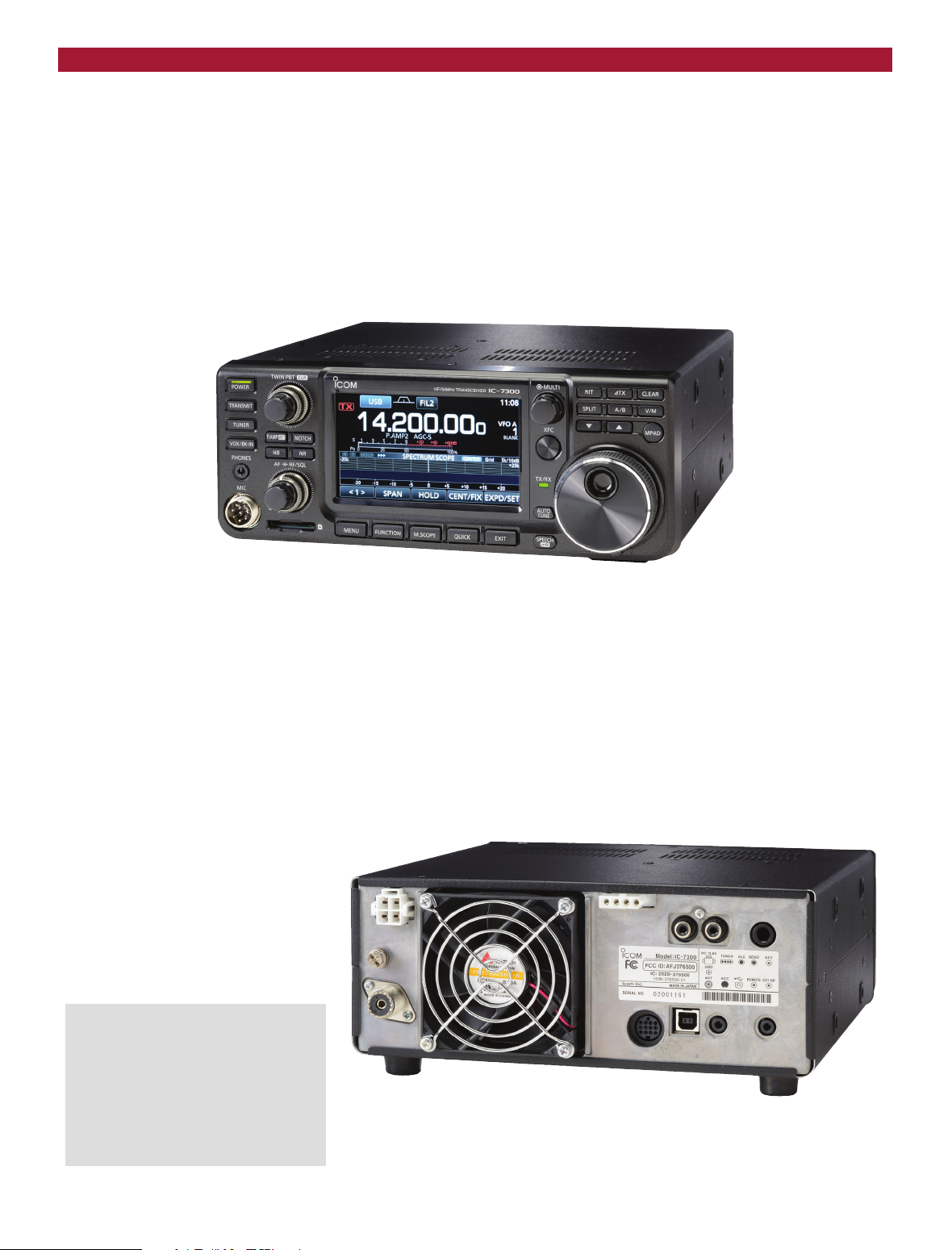
Figure 1 — The IC-7300’s rear panel has connections for a CW paddle for the internal keyer or
external key/keyer; an external speaker; ALC and TR switching for an amplifier; remote control via
the optional RS-BA1 software or an Icom CI-V device; a USB port for radio control and digital mode
operation; an ACC socket for connecting a TNC or PC for digital modes, and a jack for connection to
any of Icom’s accessory antenna tuners or tuned antennas.
Key Measurements
Summary
Icom IC-7300 HF and
6 Meter Transceiver
RM
500
Hz
102
–47
114
123
123
90
97
123
123
95
…
–30
–57
*
…
–58
–95
–122
–139
5
kHz50kHz
60
20
20 kHz Reciprocal Mixing Dynamic Range
BG
70
20
20 kHz Blocking Gain Compression (dB)
I
3
50
20
20 kHz 3rd-Order IMD Dynamic Range (dB)
RM
60
2
2 kHz Reciprocal Mixing Dynamic Range
BG
70
2
2 kHz Blocking Gain Compression (dB)
I
3
50
2
2 kHz 3rd-Order IMD Dynamic Range (dB)
I
3
TX
–20
Transmit 3rd-Order IMD (dB)
I
9
TX
–20
Transmit 9th-Order IMD (dB)
–35
bw
–55
TX
Transmit Keying Bandwidth (dB)
–80 –140
θ
–110 –150
TX
PR107
Transmit Phase Noise (dB)
Key:
20 M80 M
*
Typical
…
Note: Measurements with preamp off and IP+ on.
See text and Table 1.
Worst case band, 10 meters
140
140
110
140
140
110
–42
–35
–70
–70
–95
Table 1
Icom IC-7300, serial number 02001161
Manufacturer’s Specifications Measured in the ARRL Lab
Frequency coverage: Receive, 0.03 – 74 MHz; Receive and transmit, as specified;
transmit, 160 – 6 meter amateur bands. (5.255 – 5.405 MHz, 60 meters).
Power requirement: Receive, 0.9 A (standby), At 13.8 V dc: Receive, 1.05 A (maximum
1.25 A (maximum audio); transmit, 21 A at volume); transmit, 18.5 A (typical);
maximum power output at 13.8 V dc ±15 %. 5 mA (power off).
Modes of operation: SSB, CW, AM, FM, RTTY. As specified.
Receiver Receiver Dynamic Testing
CW sensitivity, <0.16 µV (1.8 – 29.999 MHz, Noise floor (MDS), 500 Hz bandwidth:
preamp 1 on), <0.13 µV (50 MHz preamp 1 With IP+ (Dither) Off (See text)
on), <0.16 µV (70 MHz, preamp 1 on). Preamp Off 1 2
0.137 MHz –85 –83 –82 dBm
0.475 MHz –96 –116 –118 dBm
1.0 MHz –114 –123 –125 dBm
3.5 MHz –133 –141 –143 dBm
14 MHz –133 –141 –143 dBm
28 MHz –132 –141 –143 dBm
50 MHz –130 –139 –141 dBm
With IP+ (Dither) On (See text)
3.5 MHz –123 –135 –139 dBm
14 MHz –124 –136 –140 dBm
28 MHz –122 –135 –138 dBm
Noise figure: Not specified. 14 MHz, IP+ off, preamp off/1/2:
14/6/4 dB; 50 MHz, 17/8/6 dB.
AM sensitivity: 10 dB S/N, <12.6 µV 10 dB (S+N)/N, 1-kHz, 30% modulation,
(0.5 –1.8 MHz preamp 1 on); <2.0 µV 9 kHz bandwidth:
(1.8 – 29.999 MHz, preamp 1 on); <1.0 µV Preamp Off 1 2
(50 and 70 MHz preamp 2 on). 1.0 MHz 12.20 4.16 3.71 µV
3.8 MHz 1.64 0.61 0.56 µV
29 MHz 1.82 0.66 0.58 µV
50.4 MHz 2.19 0.76 0.66 µV
FM sensitivity: 12 dB SINAD, <0.5 µV 12 dB SINAD, 15 kHz bandwidth:
(28 –29.990 MHz, preamp 1 on), 0.25 µV Preamp Off 1 2
(50 and 70 MHz, preamp 2 on). 29 MHz 0.50 0.17 0.16 µV
52 MHz 0.62 0.21 0.17 µV
Spectral sensitivity: Not specified. Preamp off/1/2: –100/–114/–118 dBm.
Blocking gain compression dynamic range: Blocking gain compression dynamic range,
Not specified. 500 Hz bandwidth†:
20 kHz offset 5/2 kHz offset
Preamp off/1/2 Preamp off
3.5 MHz 123/118/116 dB 123/123 dB
14 MHz 123/118/116 dB 123/123 dB
*
50 MHz 122/118/116 dB 122/122 dB
Reciprocal mixing dynamic range: Not specified. 14 MHz, 20/5/2 kHz offset:
preamp off, IP+ off: 114/107/101 dB;
preamp off, IP+ on, 114/108/102 dB.
ARRL Lab Two-Tone IMD Testing (500 Hz bandwidth)
Measured Measured
Band (Preamp/IP+) Spacing IMD Level Input Level‡ IMD DR
3.5 MHz (off/off) 20 kHz –133 dBm –53 dBm 80 dB
–97 dBm –16 dBm
3.5 MHz (off/on) 20 kHz –123 dBm –33 dBm 90 dB
–97 dBm –16 dBm
14 MHz (off/off) 20 kHz –133 dBm –56 dBm 77 dB
–97 dBm –16 dBm
14 MHz (two/on) 20 kHz –140 dBm –38 dBm 102 dB
–97 dBm –38 dBm
14 MHz (off/off) 5 kHz –133 dBm –56 dBm 77 dB
–97 dBm –16 dBm
14 MHz (two/on) 5 kHz –140 dBm –40 dBm 100 dB
–97 dBm –39 dBm
14 MHz (off/off) 2 kHz –133 dBm –56 dBm 77 dB
–97 dBm –21 dBm
14 MHz (off/on) 2 kHz –124 dBm –29 dBm 95 dB
–97 dBm –21 dBm
Reprinted with permission from August 2016 QST ARRL, the national association for Amateur Radio
®
www.arrl.org
Manufacturer’s Specifications Measured in the ARRL Lab
QS1608-ProdRev04
14 MHz (one/off) 2 kHz –141 dBm –63 dBm 78 dB
–97 dBm –34 dBm
14 MHz (one/on) 2 kHz –136 dBm –36 dBm 100 dB
–97 dBm –34 dBm
14 MHz (two/off) 2 kHz –143 dBm –64 dBm 79 dB
–97 dBm –34 dBm
14 MHz (two/on) 2 kHz –140 dBm –40 dBm 100 dB
–97 dBm –39 dBm
50 MHz (off/off) 20 kHz –130 dBm –41 dBm 89 dB
–97 dBm –15 dBm
50 MHz (two/on) 20 kHz –139 dBm –41 dBm 98 dB
–97 dBm –30 dBm
Second-order intercept point: Not specified. Preamp off/1/2:‡
14 MHz, +69/+45/+41 dBm;
21 MHz, +65/+67/+67 dBm;
50 MHz, +71/+71/+71 dBm.
DSP noise reduction: Not specified. 15 dB (maximum).
Audio Output: >2.5 W into 8 Ω at 10% THD. At 10% THD, 2.4 W into 8 Ω.
THD at 1 V
FM adjacent channel rejection: Not specified 29 MHz, 82 dB; 52 MHz, 79 dB.
RMS
, 0.2%.
FM two-tone third order dynamic range: 20 kHz spacing, 29 MHz, 82 dB*;
Not specified. 52 MHz, 79 dB.* 10 MHz spacing,
29 MHz, 97 dB; 52 MHz, 99 dB.
Squelch sensitivity: SSB, 5.6 µV, FM, <1 µV. At threshold: 1.58 µV 14 MHz (SSB,
preamp off); 0.08 µV (29 MHz, p2 on).
Notch filter depth: Not specified. Manual notch, 52 dB; auto-notch, 52 dB
(45 dB two tones). Attack time, 198 ms
(single tone), 2080 ms (two tones).
S-meter sensitivity: Not specified. S-9 signal, (preamp off/1/2):
14 MHz, 70.7/31.2/18.8 µV;
50 MHz, 78.4/37.5/24.5 µV.
Audio filter response: Not specified. Range at –6 dB points:**
CW (500 Hz): 342 – 860 Hz (518 Hz);
Equivalent Rectangular BW: 514 Hz;
USB (2.4 kHz): 234 – 2632 Hz (2398 Hz);
LSB (2.4 kHz): 250 – 2656 Hz (2406 Hz);
AM (9 kHz), 166 – 4477 Hz (8622 Hz).
Transmitter Transmitter Dynamic Testing
Power output: 2 – 100 W; 1 – 25 W (AM). HF, 0.7 – 104 W typical; 50 MHz,
0.5 – 97 W. 70 W typical at minimum
specified dc voltage input.
Spurious-signal and harmonic suppression: HF, typically 64 dB, 57 dB (worst case
>50 dB (1.8 – 28 MHz); >63 dB (50 MHz). 160 m), 50 MHz, 76 dB.
SSB carrier suppression: >50 dB. >70 dB.
Undesired sideband suppression: >50 dB. >70 dB.
Third-order intermodulation distortion (IMD) 3rd/5th/7th/9th order, 100 W PEP:
HF, –42/–38/–46/–57 dB (typical)
–30/–37/–44/–58 dB (worst case, 10 m);
50 MHz, –26/–37/–39/–44 dB (100 W);
50 MHz, –33/–37/–44/–62 dB (80 W)
CW keyer speed range: Not specified. 6 to 48 WPM, iambic mode B.
CW keying characteristics: Not specified. See Figures 2 and 3.
Transmit-receive turn-around time (PTT release S-9 signal, AGC fast, 15 ms.
to 50% audio output): Not specified. QSK transmit to receive time, 35 ms.
Receive-transmit turn-around time (tx delay): SSB, 14. ms; FM, 15 ms (29 MHz
Not specified. and 52 MHz).
Composite transmitted noise: Not specified. See Figure 4.
Size (height, width, depth, including protrusions): 4.0 × 9.4 × 10.7 inches. Weight, 9.3 lbs.
Price: $1500.
†
Blocking occurs at ADC overload threshold. Blocking level is same for IP+ on or off.
‡
There was no intercept of the IMD input signal and receiver IMD at the S5 (–97 dBm) level.
Figures are at threshold of ADC overload or spurious receiver response. Second-order
intercept points were determined using S5 reference.
*Measurement was noise limited at the value indicated.
**
Default values; bandwidth is adjustable.
QS1608-ProdRev02
0 0.01 0.02 0.03 0.04 0.05 0.06 0.07 0.08
Time (s)
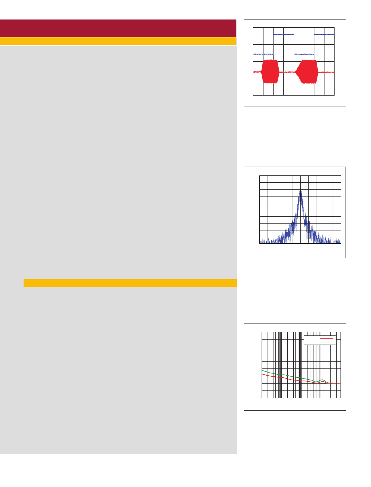
Figure 2 — CW keying waveform for the Icom
IC-7300 showing the first two dits using external
keying. Equivalent keying speed is 60 WPM.
The upper trace is the actual key closure; the
lower trace is the RF envelope. (Note that the
first key closure starts at the left edge of the
figure.) Horizontal divisions are 10 ms. The
transceiver was being operated at 100 W output
on the 14 MHz band.
0
–10
–20
–30
–40
–50
–60
Response (dB)
–70
–80
–90
–100
fc-4 fc-2 fc+2 fc+4
Frequency in kHz
QS1608-ProdRev03
f
c
Figure 3 — Spectral display of the Icom
IC-7300 transmitter during keying sideband testing. Equivalent keying speed is 60 WPM using
external keying. Spectrum analyzer resolution
bandwidth is 10 Hz, and the sweep time is 30
seconds. The transmitter was being operated
at 100 W PEP output on the 14 MHz band, and
this plot shows the transmitter output ±5 kHz
from the carrier. The reference level is 0 dBc,
and the vertical scale is 10 dB/division.
0
–
20
–
40
–
60
–
80
–
100
–
120
Level in dBc/Hz
–
140
–
160
–
180
100 Hz 1 kHz 10 kHz 100 kHz 1 MHz
14 MHz
50 MHz
Frequency Offset
Figure 4 — Spectral display of the Icom IC-7300
transmitter output during phase noise testing.
Power output is 100 W on the 14 MHz band
(red trace) and 50 MHz band (green trace). The
carrier, off the left edge of the plot, is not shown.
This plot shows composite transmitted noise
100 Hz to 1 MHz from the carrier. The reference
level is 0 dBc, and the vertical scale is in dBc/Hz.
QST® – Devoted entirely to Amateur Radio www.arrl.org Reprinted with permission from August 2016 QST

baseband signals. This IQ baseband signal
was converted to digital information by a
computer sound card, and software was
used to demodulate the received signal.
As technology improved, the signal mixing and IQ digital conversion stages were
combined in a single box, and the resulting
data was streamed to the computer for processing, typically over a USB connection.
Today, most software defined transceivers do not rely on outboard computers for
processing; all conversion and processing
takes place within dedicated circuitry that
functions as a complete transceiver. The
computer merely functions as an interface
between the transceiver and its human operator.
The IC-7300 takes the next step by eliminating the computer interface completely
and substituting knobs, buttons, and a
highly responsive touchscreen. As a result, if you
are comfortable operating a
conventional transceiver, you
can operate an IC-7300 just
as easily. You’ll find buttons
and knobs that are entirely
familiar. Best of all, the complicated menu systems found
The IC-7300 takes
the next step by
eliminating the
computer interface
completely and
substituting knobs,
buttons, and a highly
responsive
touchscreen.
in other transceivers have
been greatly streamlined in the IC-7300
through the use of the touchscreen. Navigation is as simple as tapping your finger on a
screen icon or “button.”
Some amateurs may miss the ability to
direc tly tap into the IQ stream (the
IC-7300 does not offer an IQ output), but
the IC-7300 is clearly designed to appeal
to a different audience. The hams who
embrace the IC-7300 are those who desire
the performance of an SDR, yet are put off
by the need to have a computer or some
other interfacing device between them and
the radio.
The Basics
The IC-7300 is a 100 W output, 160 through
6
meter transceiver capable of operating
SSB, CW, FM, AM, and digital modes.
The chassis is compact at 9.4 inches wide,
3.7 inches high, and 9.4 inches deep. It is
somewhat light at only 9.3 pounds, of interest for portable operation as well as home
station use. All of the knobs and buttons
have a high-quality feel.
The transceiver comes with a handheld
microphone and a printed “basic” manual.
Reprinted with permission from August 2016 QST ARRL, the national association for Amateur Radio
An accompanying CD-ROM contains a
much more detailed manual and a complete set of schematic diagrams.
Looking over the schematics, it’s obvious
that the IC-7300 wastes no time getting
from analog to digital. Received signals
are filtered, amplified, and then sent to an
analog-to-digital converter (ADC). Then
they are fed to an FPGA (field programmable gate array) for conversion and processing. All of this is transparent to the
user, though...if you sat down in front of
an IC-7300 without knowing about its architecture, you’d never guess that you were
looking at an SDR.
The “No Manual Test”
When a transceiver makes the claim of
being “user friendly,” that’s my cue to perform the No Manual Test. I simply leave
the manual in the box and attempt to set up
and operate the radio without any assistance other than
my own experience.
It took less than 5 minutes
to plug in the dc power
cord (the radio draws 21 A
maximum) and connect the
coaxial cable from my an-
tenna to the IC-7300’s single
SO-239 port. That antenna port is used for
all bands from 160 through 6 meters, and
also 4 meters — 70 MHz — in other markets. There’s no provision for a separate
receiving antenna such as a Beverage for
the low bands.
The rear panel (see Figure 1) also has connections for a CW paddle for the internal
keyer or external key/keyer, an external
speaker, digital mode interfaces, and other
accessories. I pressed the
POWER
button
and the large touchscreen came to life with
a frequency display and a bright spectrum
scope and waterfall. The audio and RF
gain knobs operated as expected, as did the
passband tuning.
I noticed the
TUNER
button and assumed
that it operated the built-in antenna tuner.
I held it down for about a second and was
rewarded with rapid clicking noises as the
tuner went to work. A few seconds later,
the IC-7300 had tuned to a flat 1:1 SWR.
You can’t miss the large VFO knob, so I
gave it a spin across the signal peaks appearing in the spectrum scope. Being in the
SSB mode at the time, I marveled at how
good the received audio sounded.
But how would I change bands? There were
no mechanical band buttons to be found, so
I knew I had to resort to the touchscreen.
Being on 20 meters, I tapped my index
finger on “14” on the frequency display.
Sure enough, an array of band-button icons
appeared. I tapped on “7” and was immediately transported to 40 meters. Through this
exercise, I also discovered that tapping on
various portions of the frequency display
also effectively altered the tuning rate of the
VFO. Direct frequency entry is also possible through the same window.
I plugged in the microphone, and within a
couple of minutes I found a fellow calling
CQ. I answered and received an outstanding signal report (he remarked that my
audio sounded particularly good). The
elapsed time from power application to
conversation was less than 10 minutes. The
IC-7300 had passed the No Manual Test
with high marks.
Of course, you will probably want to peruse
the full version (PDF format) of the manual
at some point to look a bit deeper into what
the IC-7300 can do. The manual is well organized and well written, with illustrations
and helpful hints throughout. The manual
is also available for download from Icom’s
website.
On the Air in Depth
The SDR aspects of the IC-7300 become
apparent as you spend more time listening
to signals and using the various features.
The sensitivity and selectivity of the radio
never failed to impress. Even in crowded
conditions, the IC-7300 clearly outperformed my older analog transceiver.
The manual warns that the IC-7300 could
distort in the presence of very strong signals. The receiver is indeed very “hot” —
so hot that I found myself turning off the
dual preamps and even switching in the
attenuator on occasion. Receiver sensitivity
without the preamps is adequate virtually
all of the time.
The IC-7300 has an IP+ feature, which
inserts a dither signal when you activate it.
You could say this is somewhat like adding
a strong signal off frequency, which has the
clever effect of reducing the intermodulation distortion (IMD) products. The dither
signal is noise and it raises the noise floor a
bit. As shown in Table 1, the best possible
measured performance is with IP+ and Preamp 1 on. However, as with other radios,
®
www.arrl.org

Lab Notes: Icom IC-7300
By Bob Allison, WB1GCM
Assistant Laboratory Manager
Starting with this review, the ARRL Lab will offer comments and observations about HF transceivers tested. The
Icom IC-7300 uses an RF direct sampling system. Analog
signals are picked up via the antenna and go through the
appropriate band-pass filter. Then all incoming analog signals are digitized, processed, and manipulated by software
and then converted back to analog audio for listening with
the speaker or headphones. This is quite different from
current traditional receiver architecture, in which the signal
path stays analog until the digital signal processing stage is
reached.
A key component of an RF direct sampling system is the
analog-to-digital converter (ADC). The digitization of an
analog signal is done in small steps. These steps are a type
of non-linearity that forms intermodulation (IMD) products at
low signal levels that can coherently add up.† To prevent this
unwanted effect, a dither signal (random noise) is added.
The result is an improved two-tone third-order intermodulation distortion dynamic range (3 IMD DR). The dither signal
inside the IC-7300 can be turned on and off by using the
IP+ key. With IP+ on, the sensitivity is reduced by the dither
signal, but the overall 3 IMD DR is improved. Table 1 shows
the minimum discernible signal level and the 3 IMD DR with
and without the dither signal.
All ADCs have an input signal limit. If a high enough signal
level is present at the antenna jack, the ADC can go into
an overload state. The signal level at which the overload
state is attained is known as the ADC threshold. At this
signal level, the receiver is not usable. Fortunately, the ADC
threshold is high in the IC-7300 — an in-passband signal
does not overload, even at >10 dBm. No signal blocking appears until the ADC threshold level from an adjacent signal
is reached.
The reciprocal mixing dynamic range (RMDR) and gain
compression (blocking) dynamic range figures are very
good. RMDR in particular shows the benefit of Icom’s new
synthesizer design. At 2 kHz spacing, it is nearly 25 dB better than the previous generation IC-7410. Note that these
dynamic ranges are measured with the AGC off. With the
AGC on, no blocking is observed, but the background noise
increases as the ADC threshold level is approached with
an adjacent signal 2 kHz away. Still, overall performance is
excellent for an entry-level transceiver.
For decades, it’s been generally accepted that an S-meter
reading of S-9 corresponds to an input signal level of
50 µV (–73 dBm), and that each S unit represents a change
of 6 dB (S-8 = –79 dBm, S-7 = –85 dBm, and so on). Our
measurements indicate that some manufacturers do a good
job of hitting the S-9/50 µV level, but many ARRL members
have told me that they wish there were more uniformity
with the rest of the S-meter scale. Unfortunately, in most
transceivers the S-meter scale does not accurately report
6 dB/S unit. The Icom IC-7300 uses a 3 dB/S unit scale,
for example. I hope that manufacturers will improve upon
this by adding a dBm signal level scale for more accurate
reports, and also make the meter read the same level with
the preamp(s) on or off. Turning the preamp on does not
magically add voltage at the antenna jack!
The transmitter of the IC-7300 is clean, with low phase
noise and reasonable keying sidebands. On most HF
bands, the transmit IMD third-order products are excellent,
among the best we’ve tested in 13.8 V transceivers, but the
fifth and seventh order products are on the high side. On
6 meters, all transmit IMD products are high at full RF
power output. Reducing the RF output to 80 W PEP reduces odd order products considerably.
I did not see any power overshoot in CW mode but did
find some in SSB mode. It happens very quickly, for less
than 2 ms, and can only be seen on a scope with screen
persistence. I tested the IC-7300 with an amplifier that has
protection circuitry that is sensitive to overshoot. The amplifier’s peak power meter does indicate a higher power on the
first syllable — 1800 W — then it settles down to 1500 W.
This very brief overshoot did not trip the amplifier’s protection circuitry, and appears to be of no concern. Icom recommends operating the IC-7300 with the speech compressor
off to minimize the probability of overshoot when using an
external power amplifier.
A concern pointed out by a member is the appearance of
RF output at the antenna jack for 3 ms, after the amplifier
key line opens (confirmed in the ARRL Lab). If used during
QSK (full break-in) CW operation with an amplifier with very
fast PIN diode TR switching, it is possible that the amplifier
could switch back to receive mode while RF is still flowing
from the IC-7300. In such a case, hot-switching can cause
key clicks.
At the beginning of the transmission, there is an adjustable transmit delay for RF to start flowing after the key line
closes. The delay is 6 ms with the default setting. If you use
the IC-7300 with an amplifier, check the amplifier switching
time. You will probably need to set the delay to 10 or 15 ms
(or longer), to avoid hot-switching and subsequent damage
to amplifier switching circuitry.
†
See QST
, February 2010, page 52 for more information.
it is best to leave the preamp off unless
needed. For the weakest signals, I would
turn off the IP+ for maximum sensitivity.
Speaking of noise, the IC-7300’s noise
blanker is a thing to behold. I’ve never experienced this level of noise blanker performance in a radio in this price class. All but
the worst clicks and pops were completely
eliminated. The noise reduction feature
was equally impressive. It manages to
greatly reduce background hiss and static
QST® – Devoted entirely to Amateur Radio www.arrl.org Reprinted with permission from August 2016 QST
without introducing excessive distortion
of its own.
AGC is highly adjustable. FAST, MID, and
SLOW settings are available with separate
settings for SSB, CW/RTTY, and AM
modes. Time constants are adjustable from
0.1 – 6 seconds for SSB and CW/RTTY,
and up to 8 seconds for AM. FM is fixed at
a 0.1 second FAST setting. At the default set-
ting of 6 seconds, on SSB the AGC is very
slow to recover in the presence of a strong
signal. As noted in the manual, a faster
setting works better when receiving weak
signals if strong signals are also present.
As
with many current transceivers, any kind of
impulse noise captures the AGC when the
noise blanker is off.
As with all SDR rigs, you can adjust the
filtering to whatever parameters you desire. In the IC-7300, this is accomplished
through the touchscreen. Each operating
mode provides three filter selections and

Figure 5 — The built-in RTTY decoder features
a window on the lower right with a visual tuning
aid — just line up the mark and space signals
with the vertical bars. Up to four lines of decoded text are displayed at the lower left.
Figure 6 — The IC-7300’s real-time spectrum
scope shows both panadapter and waterfall
displays. The frequency span is adjustable in
several steps and can be set to show a fixed
portion of the band or centered around the operating frequency.
Figure 7 — The SWR graphing function offers
a visual indication of antenna system SWR over
an adjustable frequency range.
you can change the bandwidths of each
one, as well as the shape between “sharp”
and “soft.”
When operating CW, it was a pleasure to
select a sharp 250 Hz filter and just slowly
tune through crowded bands, listening to
individual signals without a hint of ringing. When it comes to sending CW, earlier
SDRs occasionally had latency issues (a
lag between pressing the key and sending
or receiving the CW), but none of this is
present in the IC-7300. I quickly found that
I could send CW every bit as well as I could
with my analog rig. Break-in operation
is selected by a front panel switch, either
with full break-in (QSK) or an adjustable
delay for semi break-in. Note that in QSK
operation, the turnaround time is 35 ms,
which is slower than, for example, the
IC-7100, which is 29 ms. This limits QSK
operation at higher speeds. The
AUTO TUNE
button can help you to tune in a CW signal
to the proper pitch.
The IC-7300 includes a CW keyer with
adjustable speed, weighting, and so forth.
You can program up to eight memories to
send your call sign, signal reports, contest
exchanges, and other information. Once recorded, memories can be played back using
buttons on the lower portion of the screen
or with an external keypad. (Icom doesn’t
offer a keypad, but the manual shows the
connections needed.) There’s a similar
“voice keyer” provision for recording and
sending up to eight short voice messages.
Split frequency operation is similar to
other Icom transceivers. With
enabled, simply press and hold the
QUICK SPLIT
SPLIT
button. The transceiver turns on the split
function and sets VFO A and B to be equal.
The VFO B frequency (which will be used
for transmitting) is displayed near the bot-
Reprinted with permission from August 2016 QST ARRL, the national association for Amateur Radio
tom of the screen. Use the
XFC
button to set
your transmit frequency, or to listen on the
transmit frequency.
Audio can be tailored with the
TROL
menu. Bass and treble are adjustable
TONE CON-
separately for each voice mode (SSB, AM,
and FM), with separate adjustments for
receive and transmit. Other adjustments
include high-pass and low-pass filter cutoff frequencies for receive audio for each
mode and transmit bandwidth for SSB.
The rear panel includes TR switching and
ALC connections for using an external
power amplifier. Transmit delay is adjustable in several steps up to 30 ms to allow
amplifier relays to settle and avoid hot
switching. The Lab did observe that RF
output appears at the IC-7300’s antenna
jack for about 3 ms after the amplifier key
line opens so hot-switching an amplifier is
possible at the end of transmission during
full break-in (QSK) operation if the amplifier uses fast switching (see the accompanying sidebar).
Once you have the IC-7300 configured to
your liking, you can save the configuration
to the SD memory card (the memory card is
not included). In this way, you can store different configurations for different types of
operating. The SD card will also store many
other types of information, including received audio and transmit voice keyer audio.
Digital Modes
The IC-7300 offers a built-in RTTY decoder (see Figure 5). I tested this function, along with the “twin peaks” RTTY
filtering, and it performed quite well. The
text appears in a small window within the
main display. The radio can also save the
decoded text to the SD card for later review.
The RTTY feature includes transmit
memories for various “canned” messages.
These would be highly useful for DX hunting, especially in pileup situations. You
could program your call and response, and
simply tap the touchscreen to send.
For most digital operating generally, the
IC-7300’s USB connection is the way
to go. Transmit and receive audio, and
transmit/receive keying, are all handled
smoothly over a single cable between the
radio and your computer — no hardware
interfaces required. You only need to keep
in mind that the IC-7300 presents itself as
a “sound device” (USB Audio CODEC),
which you’ll have to select in your software
setup. For transmit/receive keying, the
IC-7300 appears as a virtual serial COM
port. To hunt down the assigned COM port
number, I had to access Device Manager
in Windows 10 and open the list of ports.
In my computer, the IC-7300’s interface
appeared as “Silicon Labs CP210x USB to
UART Bridge” and had been assigned to
COM 9 (the COM port number will likely
be different in your computer). So, once I
configured my software to use COM 9 for
rig keying, all was right with the world.
I operated the IC-7300 on several digital
modes with ease — exactly as I would with
a conventional transceiver.
With RTTY contesting in mind, I used
the IC-7300’s USB connection to handle
receive audio and FSK keying with the
popular MMTTY RTTY software and did
a little searching and pouncing during
the Alessandro Volta RTTY competition. Once again, the IC-7300 performed
perfectly. Rich Donahue, KØPIR, has a
video on YouTube at https://youtu.be/
ZCkiuzAMuZI that shows you how to
set up MMTTY for use with the IC-7300.
If you already own a digital interface, and
®
www.arrl.org

prefer to continue using it instead, don’t
worry. The IC-7300 still offers a multipin accessory port on the rear panel to accommodate your interface connections.
About that Screen
I quickly learned to love the IC-7300’s
touchscreen. It is bright and easy to read,
including the waterfall and spectrum scope
(see Figure 6). Both scopes are adjustable
and you can even zoom in for a closer look
at individual signals, or select an additional
display of the audio characteristics of the
signal. (This was particularly helpful when
sending PSK31. I could see the modulation
characteristics of my transmit signal right
there on the screen.) Tapping a signal on
the scope tunes the transceiver to that frequency. Even passband tuning is rendered
graphically. When you twist either of the
passband tuning knobs, you see the result
as an animated graphic that shows the effect of what you are doing.
While exploring the myriad features, I also
ran across a very cool SWR graphing function that behaves like an antenna analyzer.
You set your frequency parameters and
then repeatedly press the
TRANSMIT
button.
With each press, the SWR is measured and
plotted on the graph (see Figure 7). This is a
good time to mention that while the built-in
antenna tuner is designed for mismatches
that result in a maximum 3:1 SWR, it offers
a so-called “Emergency Mode” that allows
it to grapple with SWRs as high as 10:1,
albeit at reduced RF output.
Overall, the screen was well suited to my
needs, even with my aging vision, but if
you want something bigger, Icom offers
the optional $100 RS-BA1 remote control
software. With this software you can control the transceiver and display the entire
screen on your computer monitor. You can
even control the IC-7300 remotely via the
Internet.
Conclusion
So is the IC-7300 really a game-changer?
In my opinion, it clearly meets the criteria.
The IC-7300 takes the familiar ergonomic
design of an analog transceiver and blends
it seamlessly with software defined radio
technology — all at a moderate price. I
have a feeling that this approach to amateur
transceiver design is likely to spread rapidly, even to lower-end models. Years from
now we may look back at the IC-7300 and
see its introduction as the moment when
everything changed.
Manufacturer: Icom America, 12421 Willows Road NE, Kirkland, WA 98034; tel
800-872-4266; www.icomamerica.com.
See the Digital
Edition of QST
for a video
overview of the
Icom IC-7300 HF
and 6 meter
transceiver.
–
QST® – Devoted entirely to Amateur Radio www.arrl.org Reprinted with permission from August 2016 QST
 Loading...