

Page 1

FULL MANUAL
INTRODUCTION
1 PANEL DESCRIPTION
2 INSTALLATION AND CONNECTIONS
3 BASIC OPERATION
4 RECEIVING AND TRANSMITTING
HF/50 MHz TRANSCEIVER
i7300
5 SCOPE OPERATION
6 VOICE RECORDER FUNCTIONS
7 VOICE TX MEMORY OPERATION
8 USING AN SD CARD
9 MEMORY OPERATION
10 SCANS
11 ANTENNA TUNER OPERATION
12 SET MODE
13 OTHER FUNCTIONS
14 MAINTENANCE
15 UPDATING THE FIRMWARE
16 SPECIFICATIONS
17 OPTIONS
18 CONNECTOR INFORMATION
19 CONTROL COMMAND
INDEX
ABOUT CE
Page 2
Thank you for choosing this Icom product. The IC-7300 HF/50 MHz TRANSCEIVER is designed and built with Icom’s
Previous view
state of the art technology and craftsmanship. With proper care, this product should provide you with years of
trouble-free operation. We appreciate you making the IC-7300 your transceiver of choice, and hope you agree
with Icom’s philosophy of “technology rst.” Many hours of research and development went into the design of
your IC-7300.
IMPORTANT
READ ALL INSTRUCTIONS carefully completely
before using the transceiver.
SAVE THIS INSTRUCTION MANUAL— This
instruction manual contains full operating instructions
for the IC-7300
.
FEATURES
• RF Direct Sampling System
The IC-7300 employs an RF direct sampling system.
RF signals are directly converted to digital data and
processed in the FPGA. This system is a leading
technology marking an epoch in amateur radio.
• Real-Time Spectrum Scope
The spectrum scope is class-leading in resolution,
sweep speed and dynamic range. When you touch the
scope screen on the intended signal, the touched area is
magnied. The large 4.3 inch color TFT touch LCD offers
intuitive operation.
• New “IP+” Function
The new IP Plus function improves 3rd order intercept
point (IP3) performance. When a weak signal is received
adjacent to strong interference, the AD converter is
optimized against signal distortion.
• Class Leading RMDR and Phase Noise
Characteristics
The RMDR is improved to about 97dB (typical value) and
Phase Noise characteristics are also improved about
15dB (at 1 kHz frequency separation) compared to the
IC-7200.
• A 4.3 inch touch screen color display
• A built-in automatic antenna tuner
• Multi-function control for easy settings
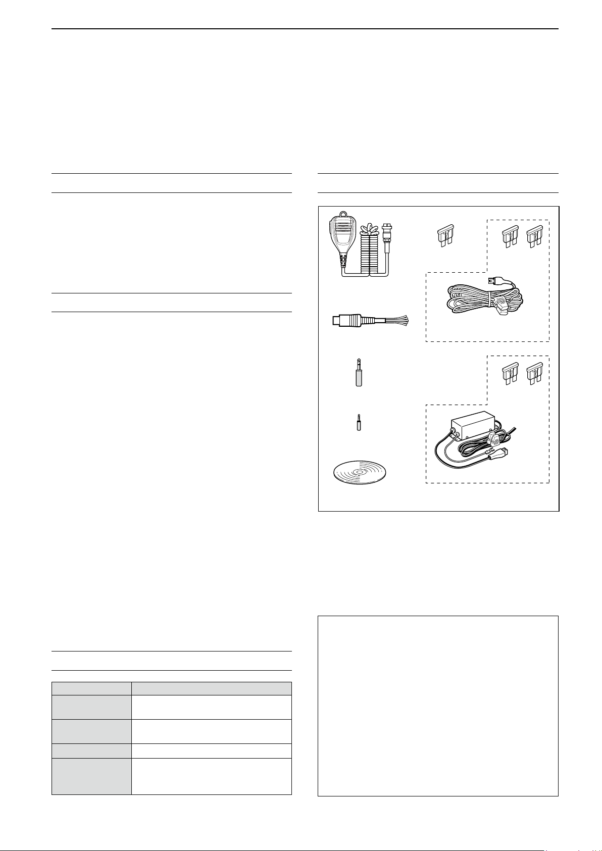
SUPPLIED ACCESSORIES
Spare fuse
(5 A)
Hand microphone
(HM-219)
DC power cable
ACC plug
(13 pin)
CW key plug
(6.35 mm: 1/4" Stereo)
Speaker plug
(3.5 mm: 1/8" Stereo)
CD
L Different types of accessories may be supplied, or may
not be supplied depending on the transceiver version.
(3 m: 9.8 ft)
For European versions
This product includes RTOS “RTX” software, and is
licensed according to the software license.
Spare fuse
(25 A)
Spare fuse
(30 A)
DC power cable
EXPLICIT DEFINITIONS
R DANGER!
R WARNING!
WORD DEFINITION
Personal death, serious injury or an
explosion may occur.
Personal injury, fire hazard or electric
shock may occur.
CAUTION
NOTE
Equipment damage may occur.
Recommended for optimum use. No
risk of personal injury, fire or electric
shock.
This product includes “zlib” open source software,
and is licensed according to the open source
software license.
This product includes “libpng” open source software,
and is licensed according to the open source
software license.
Refer to the Text les in the License folder of
included CD for information on the open source
software being used by this product.
i
Page 3
FCC INFORMATION
Previous view
This equipment has been tested and found to comply with the limits for a Class B digital device, pursuant to part
15 of the FCC Rules. These limits are designed to provide reasonable protection against harmful interference
in a residential installation. This equipment generates, uses and can radiate radio frequency energy and, if not
installed and used in accordance with the instructions, may cause harmful interference to radio communications.
However, there is no guarantee that interference will not occur in a particular installation. If this equipment does
cause harmful interference to radio or television reception, which can be determined by turning the equipment off
and on, the user is encouraged to try to correct the interference by one or more of the following measures:
• Reorient or relocate the receiving antenna.
• Increase the separation between the equipment and receiver.
• Connect the equipment into an outlet on a circuit different from that to which the receiver is connected.
• Consult the dealer or an experienced radio/TV technician for help.
WARNING: MODIFICATION OF THIS DEVICE TO RECEIVE CELLULAR RADIOTELEPHONE SERVICE
SIGNALS IS PROHIBITED UNDER FCC RULES AND FEDERAL LAW.
CAUTION: Changes or modications to this device, not expressly approved by Icom Inc., could void your
authority to operate this device under FCC regulations.
DISPOSAL
The crossed-out wheeled-bin symbol on your product, literature, or packaging reminds you that in the
European Union, all electrical and electronic products, batteries, and accumulators (rechargeable
batteries) must be taken to designated collection locations at the end of their working life. Do not
dispose of these products as unsorted municipal waste.
Dispose of them according to the laws in your area.
ABOUT CE AND DOC
Hereby, Icom Inc. declares that the versions of IC-7300 which have the “CE” symbol on the product,
comply with the essential requirements of the Radio Equipment Directive, 2014/53/EU, and the
restriction of the use of certain hazardous substances in electrical and electronic equipment Directive,
2011/65/EU.
The full text of the EU declaration of conformity is available at the following internet address:
http://www.icom.co.jp/world/support
TRADEMARKS
Icom, Icom Inc. and the Icom logo are registered trademarks of Icom Incorporated (Japan) in Japan, the United States, the
United Kingdom, Germany, France, Spain, Russia, Australia, New Zealand and/or other countries.
Microsoft and Windows are registered trademarks of Microsoft Corporation in the United States and/or other countries.
Adobe, Acrobat, and Reader are either registered trademarks or trademarks of Adobe Systems Incorporated in the United
States and/or other countries.
All other products or brands are registered trademarks or trademarks of their respective holders.
Icom is not responsible for the destruction, damage to, or performance of any Icom or non-Icom equipment, if the
malfunction is because of:
• Force majeure, including, but not limited to, res, earthquakes, storms, oods, lightning, or other natural
disasters, disturbances, riots, war, or radioactive contamination.
• The use of Icom transceivers with any equipment that is not manufactured or approved by Icom.
ii
Page 4
ABOUT THE TOUCH SCREEN
Previous view
D Touch operation
In the Full manual or Basic manual, the touch
operation is described as shown below.
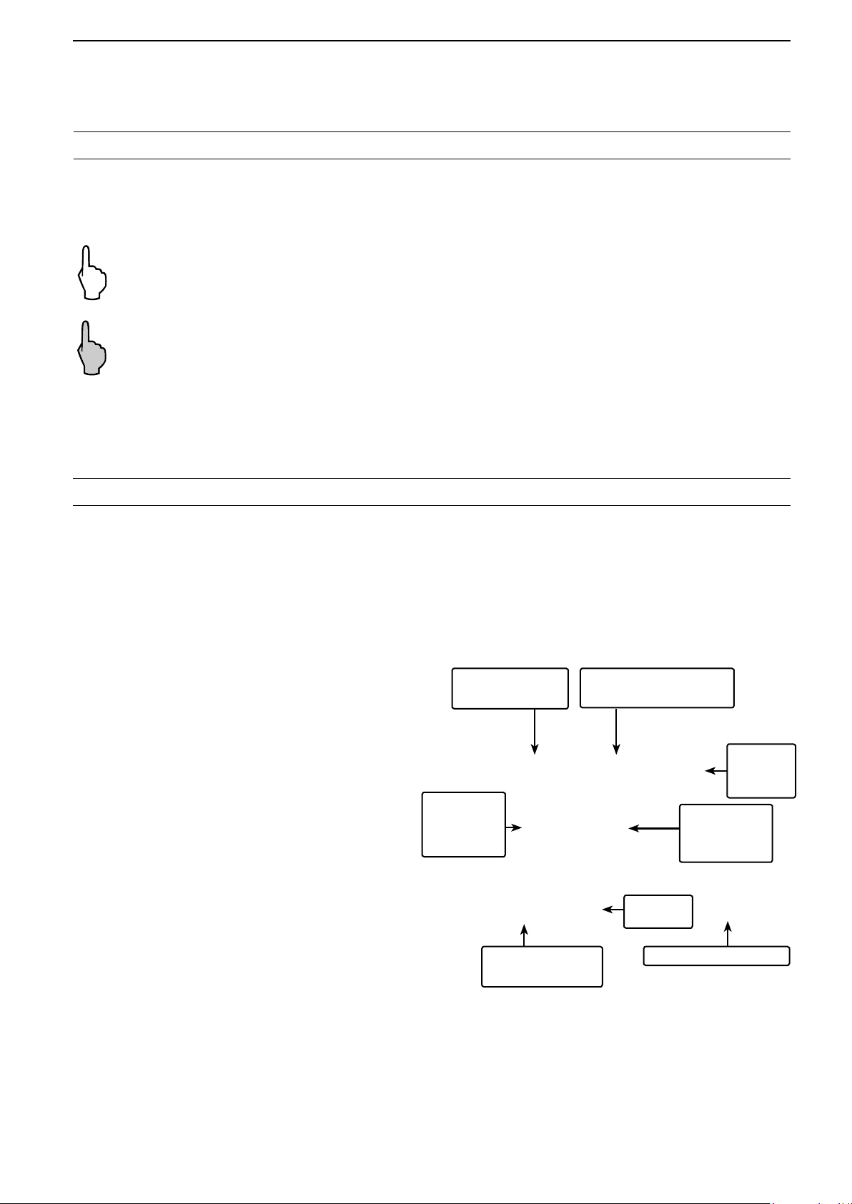
Touch
If the display is touched briey, one short beep
sounds.
Touch for 1 second
If the display is touched for 1 second, one
short and one long beep sound.
ABOUT THE SUPPLIED CD
The following items are included on the CD.
• Full manual (English)
Instructions for full operations in English, the same
as this manual.
• Basic manual (English)
Instructions for basic operations in English.
D Touch screen precautions
• The touch screen may not properly work when the
LCD protection lm or sheet is attached.
• Touching the screen with your nger nails, sharp
topped object and so on, or touching the screen
hard may damage it.
• Tablet PC’s operations such as ick, pinch in and
pinch out cannot be performed on this touch screen.
D Touch screen maintenance
• If the touch screen becomes dusty or dirty, wipe it
clean with a soft, dry cloth.
• When you wipe the touch screen, be careful not to
push it too hard or scratch it with your nger nails.
Otherwise you may damage the screen.
Starting the CD
1. Insert the CD into the CD drive.
2. Double click “Menu.exe” on the CD.
• Depending on the PC setting, the menu screen shown
below is automatically displayed.
3. Click the desired button to open the file.
L To close the Menu screen, click [Quit].
• Full manual (German)
Instructions for full operations in German.
• Basic manual (Multi-language)
Instructions for basic operations in multiple
languages.
• Schematic diagram
Includes the schematic and block diagrams.
• HAM radio Terms (English)
A glossary of HAM radio terms in English.
®
• Adobe
Acrobat® Reader® Installer
Installer for Adobe® Acrobat® Reader®.
To read the manuals or Schematic diagram,
®
Adobe
not installed it, please install the Adobe® Acrobat
Acrobat® Reader® is required. If you have
®
Reader® on the CD or download it from Adobe
Systems Incorporated’s website.
A PC with the following Operating System is required.
• Microsoft
®
Windows® 10
• Microsoft® Windows® 8.1
• Microsoft® Windows® 7
Opens the English
Basic manual
Opens
the multilanguage
Basic manual
Installs the Adobe®
Acrobat
L Different types of menu screen may be displayed,
depending on the transceiver version.
®
Opens the English Full
manual (this manual)
Opens the
Glossary
®
Reader
Opens the
German Full
manual
Closes the Menu screen
Opens the
Schematic
diagram
iii
Page 5
Functions and features of Adobe® Acrobat® Reader
Previous view
The following functions and features can be used with Adobe® Acrobat® Reader®.
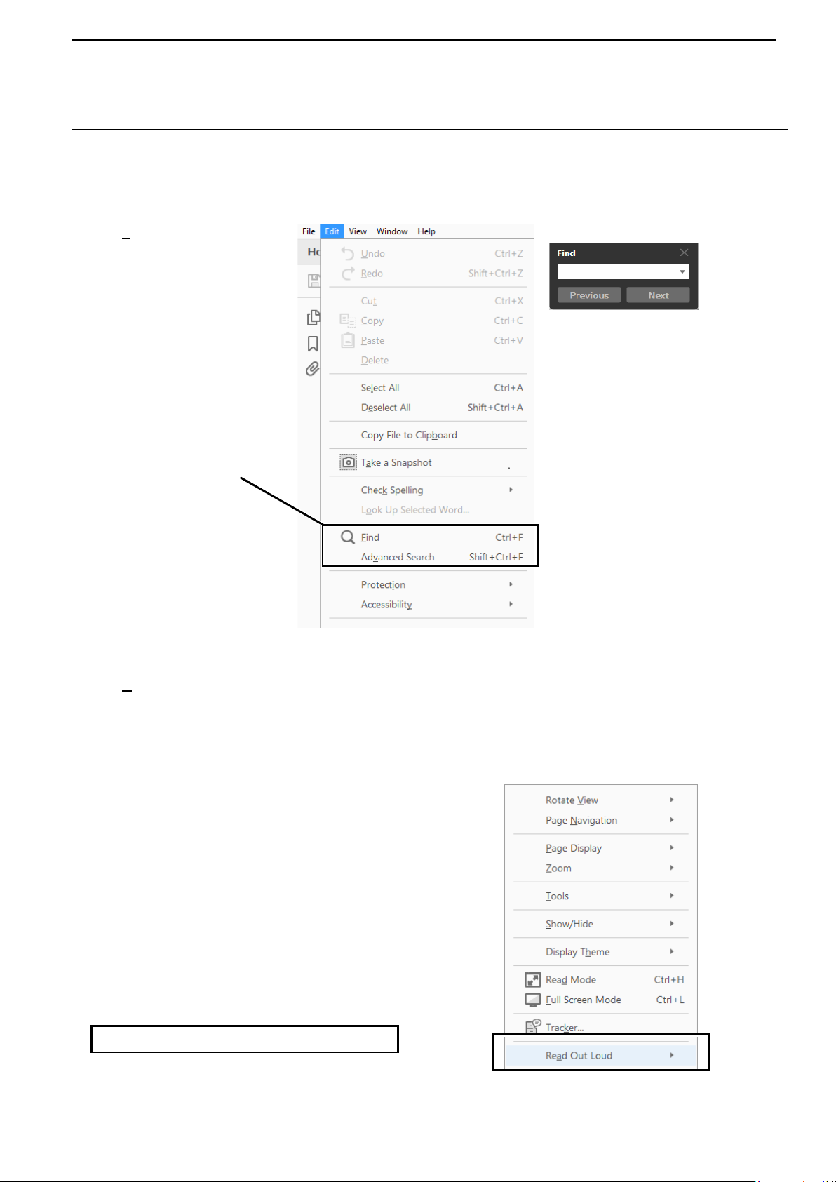
• Keyword search
Click “Find (Ctrl+F)”
or “Advanced Search
(Shift+Ctrl+F)” in the Edit menu
to open the search screen.
This is convenient when
searching for a particular word or
phrase in this manual.
* The menu screen may differ,
depending on the Adobe
®
Reader
version.
®
Acrobat®
Click to open the nd or search
screen or advanced search screen.
• Find screen
• Advanced search screen
®
• Printing out the desired pages.
Click “Print” in File menu, and then select the paper
size and page numbers you want to print.
* The printing setup may differ, depending on the
printer. Refer to your printer’s instruction manual
for details.
* Select “A4” size to print out the page in the
equalized size.
• Read Out Loud feature.
The Read Out Loud feature reads aloud the text in
this Instruction Manual.
Refer to the Adobe
®
Acrobat® Reader® Help for the
details.
( This feature may not be usable, depending on your
PC environment including the operating system.)
* The screen may differ, depending on the Adobe® Acrobat®
Reader
iv
®
version.
Page 6
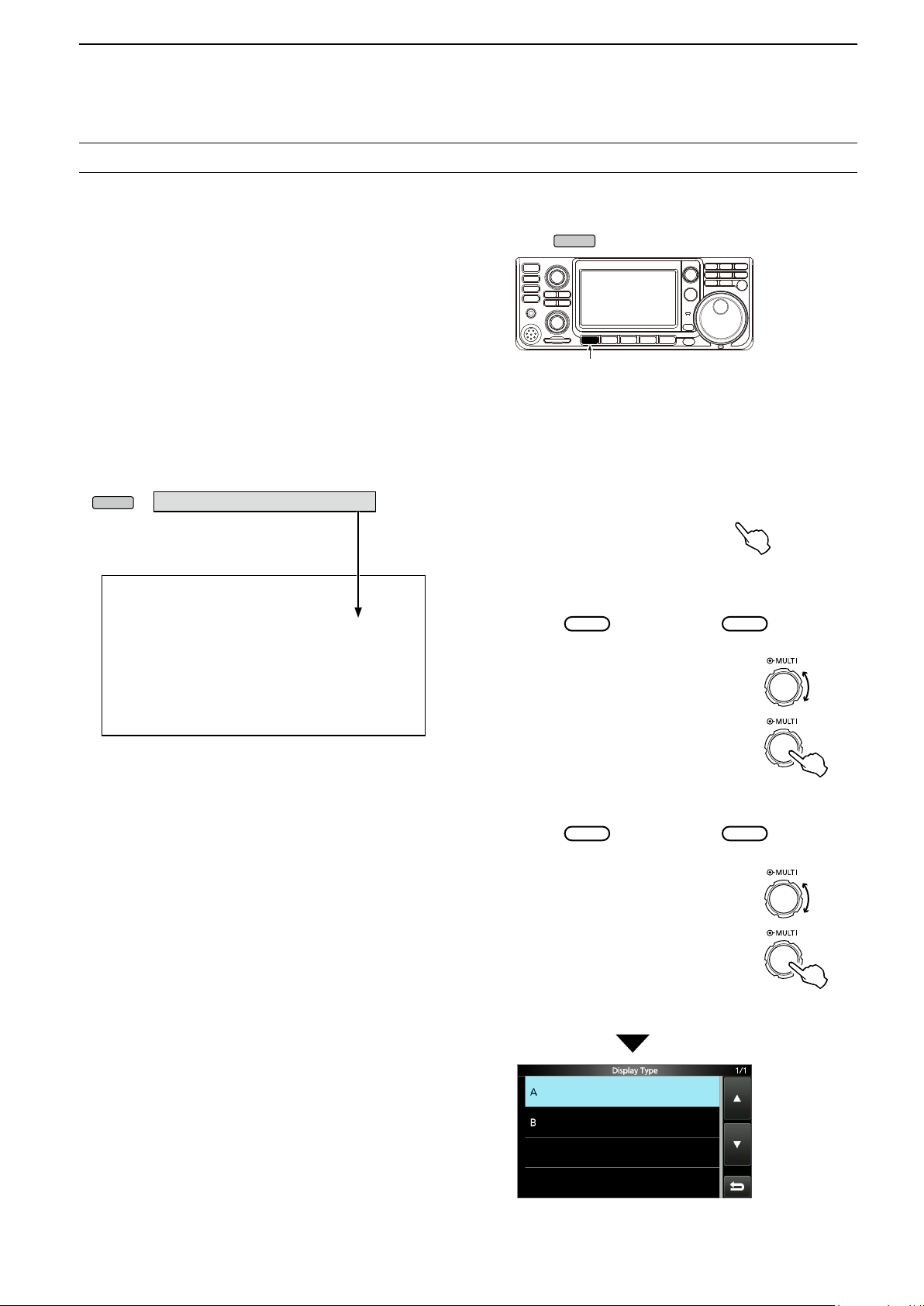
ABOUT THE INSTRUCTIONS
MENU
MENU
MULTI
MULTI
Rotate
MULTI
MULTI
Rotate
Previous view
The Full and Basic manuals are described based on
the following:
“ ” (Quotation marks):
Used to indicate icons, setting items, and screen titles
displayed on the screen.
The screen titles are also indicated in uppercase letters.
(Example: FUNCTION screen)
[ ] (brackets):
Used to indicate keys.
Routes to the set modes and setting screens
Routes to the set mode, setting screen and the setting
items are shown in the following manner.
» SET > Display > Display Type
Instruction example
Detailed instruction
1. Push
• Opens the MENU screen.
.
Push
2. Touch [SET].
MENU screen
• Opens the SET screen.
3. Rotate
, and then push
“Display.”
to select
4. Rotate
“Display Type.”
SET screen
, and then push
DISPLAY screen
Push
to select
Push
“Display Type” screen
v
Page 7

PRECAUTIONS
Previous view
R DANGER HIGH RF VOLTAGE! NEVER touch an
antenna or antenna connector while transmitting. This could
cause an electrical shock or burn.
R DANGER! NEVER operate the transceiver near
unshielded electrical blasting caps or in an explosive
atmosphere. This could cause an explosion and death.
R WARNING RF EXPOSURE! This device emits Radio
Frequency (RF) energy. Extreme caution should be
observed when operating this device. If you have any
questions regarding RF exposure and safety standards
please refer to the Federal Communications Commission
Ofce of Engineering and Technology’s report on
Evaluating Compliance with FCC Guidelines for Human
Radio Frequency Electromagnetic Fields (OET Bulletin 65).
R WARNING! NEVER operate the transceiver with a
headset or other audio accessories at high volume levels. If
you experience a ringing in your ears,reduce the volume or
discontinue use.
R WARNING! NEVER apply AC power to the [DC13.8V]
socket on the transceiver rear panel. This could cause a re
or damage the transceiver.
R WARNING! NEVER apply more than 16 V DC to the
[DC13.8V] socket on the transceiver rear panel. This could
cause a re or damage the transceiver.
R WARNING! NEVER reverse the DC power cable
polarity. This could cause a re or damage the transceiver.
R WARNING! NEVER remove the fuse holder on the DC
power cable. Excessive current caused by a short could
cause a re or damage the transceiver.
R WARNING! NEVER let metal, wire or other objects
contact the inside of the transceiver, or make incorrect
contact with connectors on the rear panel. This could cause
an electric shock or damage the transceiver.
R WARNING! NEVER operate or touch the transceiver
with wet hands. This could cause an electric shock or
damage to the transceiver.
R WARNING! Immediately turn OFF the transceiver power
and remove the DC power cable from the transceiver if it
emits an abnormal odor, sound or smoke. Contact your
Icom dealer or distributor for advice.
R WARNING! NEVER put the transceiver on an unstable
place where the transceiver may suddenly move or fall.
This could cause an injury or damage the transceiver.
R WARNING! NEVER operate the transceiver during a
lightning storm. It may result in an electric shock, cause
a re or damage the transceiver. Always disconnect the
power source and antenna before a storm.
CAUTION: NEVER expose the transceiver to rain, snow or
any liquids.
CAUTION: NEVER change the internal settings of the
transceiver. This could reduce transceiver performance
and/or damage to the transceiver. The transceiver warranty
does not cover any problems caused by unauthorized
internal adjustments.
CAUTION: NEVER install or place the transceiver in a
place without adequate ventilation, or block any cooling
vents on the top, rear, sides or bottom of the transceiver.
Heat dissipation may be reduced and damage the
transceiver.
CAUTION: NEVER use harsh solvents such as Benzine or
alcohol when cleaning, as they will damage the transceiver
surfaces.
CAUTION: NEVER leave the transceiver in areas with
temperatures below –10°C (+14°F) or above +60°C
(+140°F) for mobile operations.
CAUTION: NEVER place the transceiver in excessively
dusty environments. This could damage the transceiver.
DO NOT place the transceiver against walls or putting
anything on top of the transceiver. This may overheat the
transceiver.
BE CAREFUL! The Main unit will become hot when
operating the transceiver continuously for long periods of
time.
CAUTION: If you use a linear amplier, set the
transceiver’s RF output power to less than the linear
amplier’s maximum input level, otherwise a high input
could damage the linear amplier.
CAUTION: Use only Icom supplied or optional
microphones. Other manufacturer’s microphones may have
different pin assignments, and could damage the connector
and/or the transceiver.
NEVER leave the transceiver in an insecure place to avoid
use by unauthorized persons.
Turn OFF the transceiver’s power and/or disconnect the AC
power cable when you will not use the transceiver for a long
period of time.
Turn OFF the transceiver’s power and/or disconnect the DC
power cable when you will not use the transceiver for long
period of time.
The LCD display may have cosmetic imperfections
that appear as small dark or light spots. This is not a
malfunction or defect, but a normal characteristic of LCD
displays.
vi
Page 8

Section 1 PANEL DESCRIPTION
Previous view
Front panel ............................................................................. 1-2
Rear panel .............................................................................. 1-4
Touch screen .......................................................................... 1-5
D Multi-function menus ....................................................... 1-7
D MENU screen ................................................................. 1-7
D FUNCTION screen ......................................................... 1-7
D QUICK MENU ................................................................. 1-7
Keyboard entering and editing................................................ 1-8
D Entering and editing characters ...................................... 1-8
D Keyboard types ............................................................... 1-8
D Entering and editing ........................................................ 1-8
D Entering and editing example ......................................... 1-9
1-1
Page 9
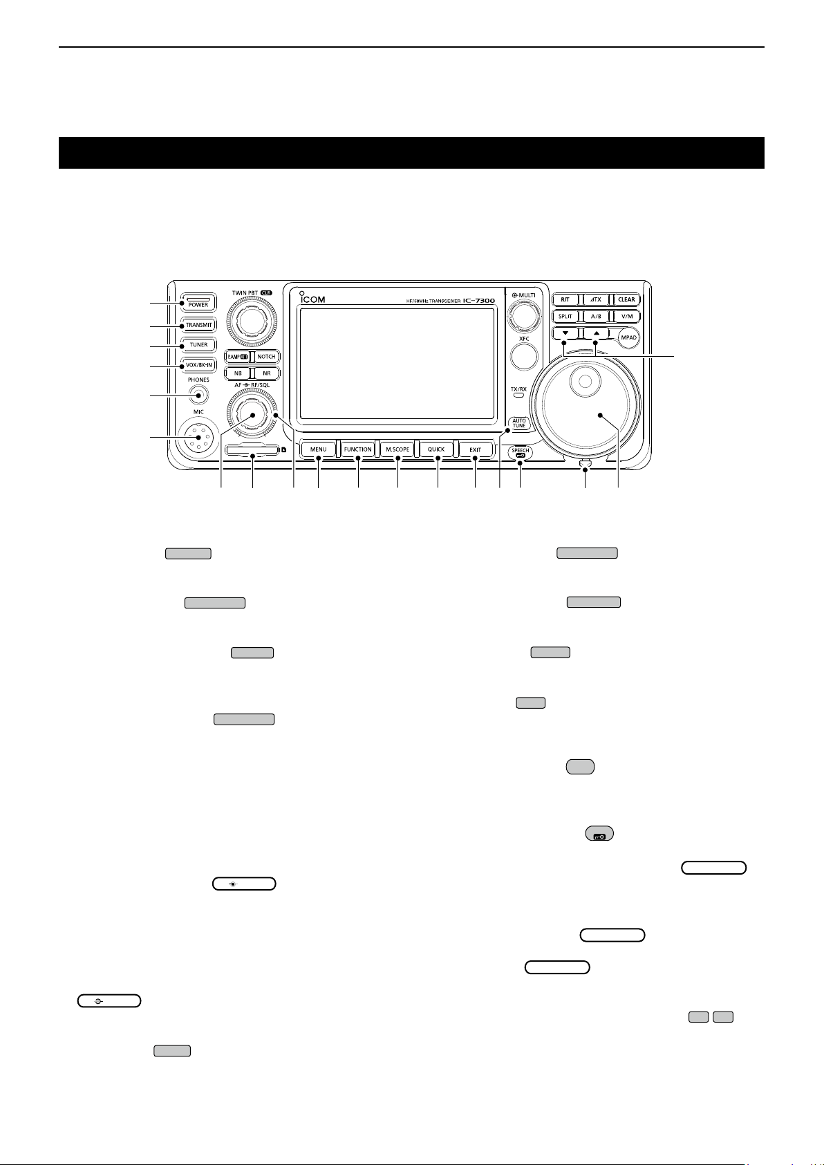
PANEL DESCRIPTION
POWER
TRANSMIT
TUNER
VOX/BK-IN
AF RF/SQL
AF RF/SQL
MENU
FUNCTION
M.SCOPE
QUICK
EXIT
AUTO
TUNE
SPEECH
MAIN DIAL
MAIN DIAL
MAIN DIAL
Previous view
1
Front panel
This section describes the keys, controls and dials that you use to operate the IC-7300.
Refer to the pages posted beside each key, control, or dial for details.
q
w
e
r
t
y
!9
i !0 !1 !2 !3 !4 !6 !7u o !8!5
q POWER KEY
(p. 3-2)
Turns the transceiver ON or OFF.
w TRANSMIT KEY
(p. 3-10)
Toggles between transmit and receive.
e ANTENNA TUNER KEY
(p. 11-2)
Turns the antenna tuner ON or OFF, or activates
the tuner.
r VOX/BREAK-IN KEY
Turns the VOX function (p. 4-10) and Break-in
function (p. 4-15) ON or OFF.
t HEADPHONE JACK [PHONES] (p. 2-2)
Connects to a standard stereo headphones.
y MICROPHONE CONNECTOR [MIC] (p. 2-2)
Connects to the supplied or an optional microphone.
u VOLUME CONTROL
(p. 3-2)
Adjusts the audio output level.
i SD CARD SLOT [SD CARD] (p. 8-2)
Accepts an SD card.
o RF GAIN CONTROL/SQUELCH CONTROL
(p. 3-10)
Adjusts the RF gain and squelch threshold levels.
!0 MENU KEY
(p. 1-7)
Opens the MENU screen.
!1 FUNCTION KEY
(p. 1-7)
Displays the FUNCTION screen.
!2 MINI SCOPE KEY
(p. 5-2)
Displays the Mini Scope or Spectrum Scope.
!3 QUICK KEY
(p. 1-7)
Displays the QUICK MENU.
!4 EXIT KEY
(p. 1-7)
Exits a setting screen or returns to the previous
screen.
!5 AUTO TUNE KEY
(p. 4-16)
Automatically tunes the operating frequency to a
received CW signal.
!6 SPEECH/LOCK KEY
Announces the operating frequency or receiving
mode (p. 13-2), or electronically locks
(p.3-10).
!7 FRICTION ADJUSTER (13-2)
Adjusts the friction of
!8 MAIN DIAL
(p. 3-4)
.
Changes the operating frequency.
!9 MEMORY CHANNEL UP/DOWN KEY ▲/▼
(p. 9-3)
Changes the Memory channel.
1-2
Page 10
PANEL DESCRIPTION
MPAD
V/M
CLEAR
A/B
TX
RIT
SPLIT
MULTI
XFC
NOTCH
TWIN PBT
P.AMP
ATT
Previous view
1
Front panel (Continued)
@0 MEMO PAD KEY
#3#4
(p. 9-6)
#2
#1 #0
Sequentially calls up the contents in the Memo
Pads, or saves the displayed contents into the
Memo Pad.
@1 VFO/MEMORY KEY
(p. 3-2)
Switches between the VFO and Memory mode, or
copies the memory channel contents to the VFO.
@8@9 @3
@6
@5@7 @4
@2
@1
@0
@8 TRANSMIT FREQUENCY CHECK KEY
(p. 4-13)
Enables you to monitor the transmit frequency while
holding it down in the Split mode.
@9 TX/RX INDICATOR (p. 3-10)
Lights red while transmitting and lights green while
receiving.
@2 CLEAR KEY
Clears the RIT (p. 4-3) or TX shift frequency
(p. 4-11).
@3 A/B KEY
(p. 3-2)
Switches between VFO A and VFO B, or sets the
selected VFO’s frequency to the other VFO.
@4 TX KEY
(p. 4-11)
Turns the TX function ON or OFF.
@5 RIT KEY
(p. 4-3)
Turns the Receiver Incremental Tuning (RIT)
function ON or OFF.
@6 SPLIT KEY
(p. 4-13)
Turns the Split function ON or OFF.
@7 MULTI-FUNCTION CONTROL
(p. 1-7)
Displays the Multi-function menu for various
adjustments, or selects a desired item.
#0 NOISE REDUCTION KEY NR (p. 4-9)
Turns the Noise Reduction function ON or OFF.
#1 NOTCH KEY
(p. 4-9)
TurnstheNotchlterONorOFF.
#2
TWIN PASSBAND TUNING CONTROL
CLR
(p. 4-5)
AdjuststheIFlter’spassbandwidthbyrotating,
and clears the setting by holding down for 1 second.
#3 PREAMP/ATTENUATOR KEY
(p. 4-3)
Turns ON or OFF, and selects one of two receive
RFpreampliersorturnstheAttenuatorONorOFF.
#4 NOISE BLANKER KEY NB (p. 4-8)
Turns the Noise Blanker ON or OFF.
1-3
Page 11
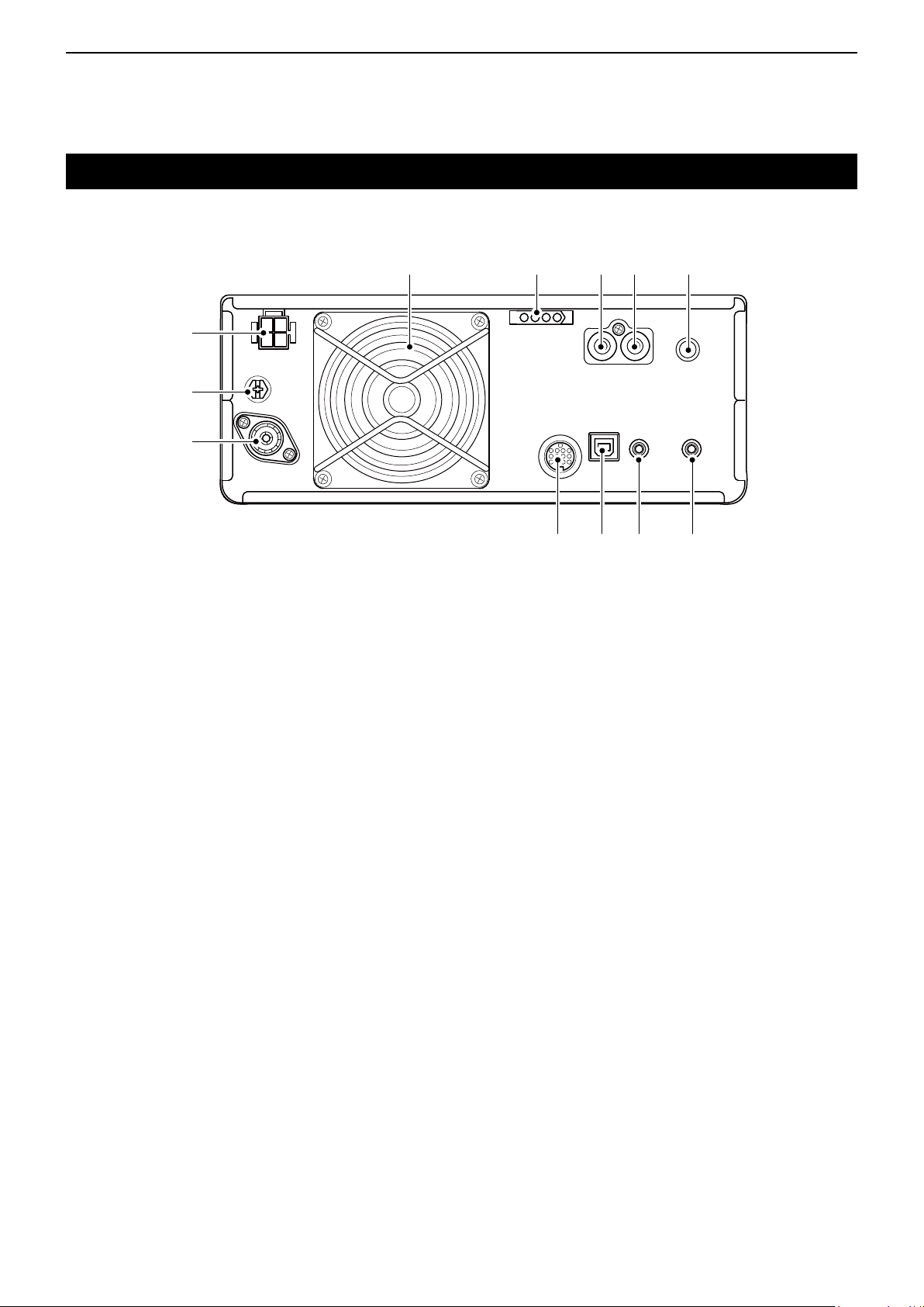
PANEL DESCRIPTION
Previous view
1
Rear panel
o!0!1 i!2
q
w
e
q DC POWER SOCKET [DC 13.8 V] (p. 2-3)
Accepts 13.8 V DC through the DC power cable.
w GROUND TERMINAL [GND] (p. 2-2)
Connects to ground to prevent electrical shocks,
TVI, BCI and other problems.
e ANTENNA CONNECTOR [ANT] (p. 2-3)
Connectstoa50ΩPL-259coaxconnector.
r SOCKET [ACC] (p. 2-3)
Connects to devices to control an external unit or to
control the transceiver.
t USB PORT (B TYPE) [USB] (p. 2-3)
Connects to a PC.
y CI-V REMOTE CONTROL JACK [REMOTE]
(p. 2-3)
Connects to a PC or other transceiver for external
control.
r y ut
i KEY JACK [KEY] (p. 2-3)
Connects to a straight key, external electronic
keyer,orapaddlewith6.35mm(1⁄4")stereoplug.
o SEND CONTROL JACK [SEND] (p. 2-3)
Connects to control transmit with non-Icom external
units.
!0 ALC INPUT JACK [ALC] (p. 2-3)
Connects to the ALC output jack of a non-Icom
linearamplier.
!1 TUNER CONTROL SOCKET [TUNER] (p. 2-3)
Accepts the control cable from an optional
AH-4 automatic antenna tuner or AH-740
automatic tuning antenna.
!2 COOLING FAN
Cools the PA unit when necessary.
u EXTERNAL SPEAKER JACK [EXT-SP] (p. 2-3)
Acceptsa4~8Ωexternalspeaker.
1-4
Page 12

PANEL DESCRIPTION
Previous view
1
Touch screen
This section describes the icons, screens, dialogs, readouts and so on that are displayed on the IC-7300 screen.
Refer to the pages posted beside each item for details.
q w e t i o !0 !1 !2
q TUNE ICON (p. 11-2)
Appears while tuning the antenna.
w MODE INDICATOR (p. 3-3)
Displays the selected operating mode.
e PASSBAND WIDTH INDICATOR
(p. 4-5)
Graphically displays the passband width for twin
PBT operation and the center frequency for IF shift
operation.
r TONE INDICATOR (p. 4-29)
Displays the selected tone type in the tone
operation mode.
t IF FILTER INDICATOR (p. 4-6)
DisplaystheselectedIFlter.
yr u
!3
!4
!5
o M1~M8/T1~T8/OVF ICON
Displays “M1”~“M8” while “External Keypad” on
the CONNECTORS screen is set to ON and using
the Memory Keyer function (p. 4-18). Displays
“T1”~“T8” while using the Voice TX memory. (p. 7-4)
Displays “OVF” when an excessively strong signal is
received.
!0 VOICE RECORDER ICON (p. 6-2)
Appears while recording.
!1 SD CARD ICON (p. 8-2)
Appears when an SD card is inserted, or blinks
while accessing the SD card.
!2 CLOCK READOUT (p. 12-11)
Displays the current local time.
Touch the readout to display both the current local
time and UTC time.
y QUICK TUNING ICON (p. 3-4)
Appears when the Quick Tuning Step function is
ON.
u IP PLUS ICON (p. 4-7)
Appears when the IP Plus function is ON.
i MEMORY NAME READOUT/AUTO TUNE ICON
Displays the memory name if entered (p. 9-5), or
displays the “AUTOTUNE” icon when the Auto
Tuning function is ON (p. 4-16).
!3 SPLIT ICON (p. 4-13)
Appears when the Split function is ON.
!4 VFO/MEMORY ICON (p. 3-2)
“VFO A” or “VFO B” appears when the VFO
mode is selected, and “MEMO” appears when the
Memory mode is selected.
!5 MEMORY CHANNEL READOUT (p. 3-2)
Displays the selected memory channel number.
1-5
Page 13
PANEL DESCRIPTION
AF RF/SQL
TX
Previous view
1
Touch screen (Continued)
@7
@6
@5
!6
@4
@3
@2
!6 LOCK ICON
(p. 3-10)
Appears while the Lock Function is ON.
appears while the 1/4 Tuning function is ON.
(p. 3-5)
!7 RIT ICON (p. 4-2)
Appears while the RIT function is ON.
!8 TX ICON (p. 4-11)
Appears while the TX function is ON.
!9 SHIFT FREQUENCY READOUT
Displays the shift offset of the RIT (p. 4-2) or
TX (p. 4-11) functions, while the functions are ON.
@0 SPECTRUM SCOPE SCREEN (p. 5-2)
Displayed while using the Spectrum Scope.
!7
!8
!9
@0
@1
@3 RF GAIN ICON (p. 3-10)
Appears when
(outer) is set to the
counterclockwise from the 11 o’clock position. The
icon indicates that the RF gain is reduced.
@4 BK-IN/F-BKIN/VOX INDICATOR (p. 4-15)
Appears while the Semi Break-in, Full Break-in or
VOX function is ON.
@5 FREQUENCY READOUT (p. 3-4)
Displays the operating frequency.
@6 LMT ICON (p. 13-4)
Appearsifthepowerampliertemperature
becomes extremely high and the Protection
function is activated after transmitting continuously
for long periods of time.
@1 FUNCTION DISPLAY
Displays the operating parameters, modes,
@2 MULTI-FUNCTION METER (p. 3-11)
Displays various strengths and levels, depending
frequencies and indicators, depending on your
selections.
on the function you select.
@7 TX STATUS INDICATOR (p. 3-10)
Displays the transmit status of the displayed
frequency.
• appears while transmitting.
•
appears when the selected frequency is outside of
the amateur band frequency range.
•
appears while transmitter is inhibited (p. 3-4)
1-6
Page 14
PANEL DESCRIPTION
MULTI
VOX/BK-IN
NOTCH
MULTI
MENU
FUNCTION
EXIT
QUICK
Previous view
1
Touch screen (Continued)
D Multi-function menus
Touch the edge to
turn ON and OFF
Multi-function menu
z Open the Multi-function menu by pushing
(Multi-function control).
z Open different types of menus by holding down
, NB, NR, or
z While the Multi-function menu is opened, touch the
desired item and rotate
value.
Multi-function menu items
SSB SSB-D CW RTTY
RF POWER RF POWER RF POWER RF POWER
MIC GAIN MIC GAIN KEY SPEED
*
COMP
MONITOR
RF POWER RF POWER LEVEL LEVEL
MIC GAIN MIC GAIN DEPTH
MONITOR
NOTCH VOX BK-IN
POSITION GAIN DELAY
WIDTH
*
MONITOR
FM AM NB NR
*
MONITOR
*
ANTI VOX
DELAY
VOICE DELAY
SHORT
*
*
*
* Touch the edge to turn the function ON or OFF, or
adjust.
for 1 second.
to set the desired
CW PITCH
MONITOR
WIDTH
TPF
*
Rotate
Push
*
D FUNCTION screen
Function
name
Selected
value
Lights blue
or orange
when used
FUNCTION screen
z Open the FUNCTION screen by pushing
LTo close the FUNCTION screen, push
.
FUNCTION screen list
*
P.AMP/ATT AGC
OFF FAST OFF OFF
P.AMP1 MID AN ON
P.AMP2 SLOW MN
*
1
ATT
*
2
NR
OFF OFF OFF OFF
ON ON ON BKIN
*
2
COMP
OFF OFF WIDE OFF
ON TONE MID ON
*
2
MONI
OFF
ON
2
IP+ VOX
*
2
TONE
TSQL NAR
*
NOTCH
2
*
2
TBW 1/4
NB
BKIN
F-BKIN
*1 Touch for 1 second to select the function.
*2 Touch for 1 second to open its function menu.
D QUICK MENU
.
*
2
*
2
D MENU screen
z Open the MENU screen by pushing
z Open the QUICK MENU by pushing
.
.
1-7
Page 15
PANEL DESCRIPTION
MENU
QUICK
MENU
Previous view
1
Keyboard entering and editing
D Entering and editing characters
You can enter and edit the items in the following table.
Category Screen Selectable characters
MENU MY CALL
MEMORY MEMORY NAME
A to Z, 0 to 9, (space), / @ - .
A to Z, a to z, 0 to 9, (space), @ % & # +
-=[]/():;˄!?.,
Total
characters
10
10
Information
KEYER MEMORY
FUNCTION
SD Card FILE NAME
RTTY MEMORY
VOICE TX
RECORD
AtoZ,0to9,(space),/?^.,@
AtoZ,0to9,(space),!$&?"'-/.,:;
( ) ↵
AtoZ,atoz,0to9,(space),˽!"#$%&
'()*+,-./:;<=>?@[
AtoZ,atoz,0to9,(space),˽!"#$%&
'()*+,-./:;<=>?@[
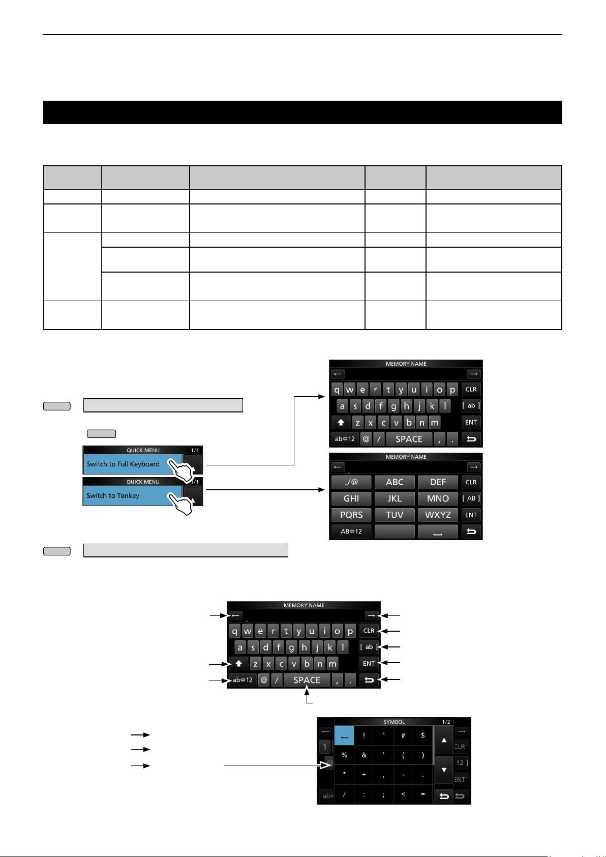
D Keyboard types
You can select the Full Keyboard or Ten-key in
“Keyboard Type” on the FUNCTION screen. (p. 12-7)
» SET>Function>Keyboard Type
L You can also temporarily switch in the QUICK MENU by
pushing
L You can select the full keyboard layout in “Screen Full
Keyboard Layout” on the FUNCTION screen. (p.12-7)
»
SET>Function>Screen Full Keyboard Layout
.
\ ] ^_ˋ{�}~
\ ] ^_ˋ{�}~
70
70
16
15
“*” (asterisk) has its unique use.
Illegal characters:
/:;*<>
D Entering and editing
Moves the cursor backward
Enters an uppercase letter
Selects alphabet mode
or number mode
Alphabet mode
Number mode
Symbol mode
Moves the cursor forward
Clears the entered character
Selects the character type
Saves the entry
Cancels entry and returns to the
previous screen
Enters a space
1-8
Page 16
PANEL DESCRIPTION
MENU
Rotate
Previous view
1
Keyboard entering and editing (Continued)
D Entering and editing example
Entering “DX spot 1” in the Memory channel 2
1. Open the MEMORY screen.
» MEMORY
2. Touch the memory channel 2 for 1 second.
You can also
open the
QUICK MENU
by touching this
key.
• Opens the QUICK MENU.
3. Select “Edit Name.”
• Opens the MEMORY NAME screen.
4. Touch [ ], and then touch [D].
9. Touch [ab].
• Opens the entry CHARACTER TYPE screen.
10. Touch [12].
Push
11. Touc h [1] .
12. Touch [ENT] to save the entry.
5. Touch [ ] again, and then touch [X].
6. Touch [SPACE].
7. Touch [s], [p], [o], and then [t].
8. Touch [SPACE].
• Returns to the previous screen.
• Enters a space.
• Enters a space.
1-9
Page 17

Section 2 INSTALLATION AND CONNECTIONS
Previous view
Selecting a location ................................................................ 2-2
Heat dissipation ...................................................................... 2-2
Grounding ............................................................................... 2-2
Front panel connection ........................................................... 2-2
Rear panel connection............................................................ 2-3
Connecting an external DC power supply ............................. 2-4
Connecting the antenna tuner ................................................ 2-4
FSK and AFSK connections ................................................... 2-5
Linear amplier connections ................................................... 2-6
D Connecting the IC-PW1/IC-PW1EURO .......................... 2-6
D Connecting a non-Icom linear amplier .......................... 2-6
2-1
Page 18
INSTALLATION AND CONNECTIONS
Previous view
2
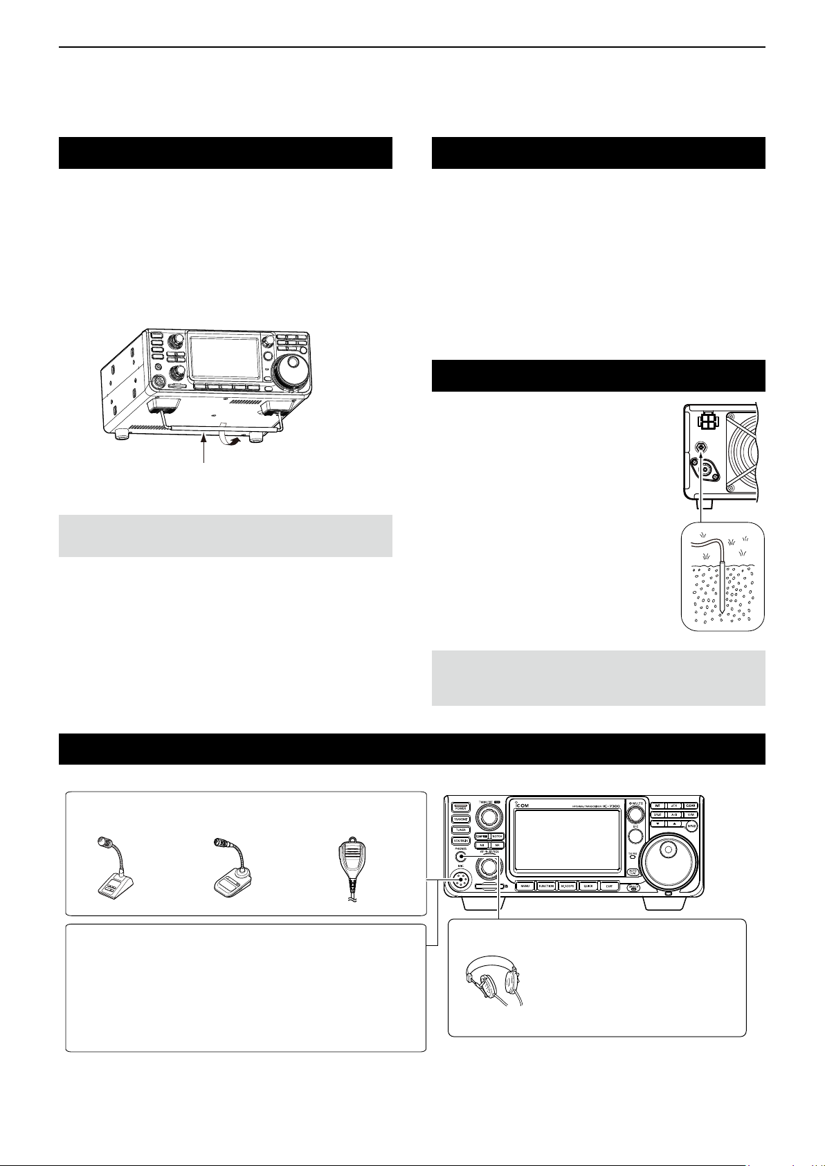
Selecting a location
Select a location for the transceiver that allows
adequate air circulation, free from extreme heat, cold
or vibrations, and other electromagnetic sources.
The transceiver has a stand for desktop use.
Stand
CAUTION: NEVER carry the transceiver by holding the
stand, dials, controls and so on. This may damage them.
Heat dissipation
• DO NOT place the transceiver against walls or put
anything on top of the transceiver. This may block
airow and overheat the transceiver.
• NEVER install the transceiver in a place without
adequate ventilation. Heat dissipation may be
reduced, and the transceiver may be damaged.
• DO NOT touch the transceiver after transmitting
continuously for long periods of time. The transceiver
may become hot.
Grounding
To prevent electrical shock, television
interference (TVI), broadcast
interference (BCI) and other
problems, ground the transceiver
using the ground terminal [GND] on
the rear panel.
For best results, connect a heavy
gauge wire or strap to a long ground
rod. Make the distance between the
[GND] terminal and ground as short
as possible.
Front panel connection
[MIC] (Microphone) connector
SM-50
(Option)
Using an External Keypad
You can control the CW memory keyer, Voice memory or
RTTY memory keyer transmission from an external keypad by
connecting the control circuit to the [MIC] connector. Set the
external keypad settings to ON on the CONNECTORS screen
to use the external keypad. (p. 12-8)
L The external keypad is not supplied by Icom.
See page 18-3 for the connector details.
SM-30
(Option)
HM-219
(Supplied)
RWARNING! NEVER connect the [GND] terminal
to a gas or electric pipe, since the connection could
cause an explosion or electric shock.
[PHONES] Headphones
Accepts headphones with 8~16 Ω
impedance.
• Outputs 5 mW into an 8 Ω load.
• The volume level may differ,
depending on the headphones.
2-2
Page 19

INSTALLATION AND CONNECTIONS
Previous view
2
Rear panel connection
[DC 13.8 V] DC power supply
(p. 18-4)
Use the optional
PS-126 or a power
supply with 13.8 V DC
output and a current
capacity of at least
21 A.
PS-126 (option)
[GND] (Ground)
Grounding prevents
electrical shock, TVI
and other problems.
[ANT] (antenna) connector
[ALC]/[SEND] jack
Connect with an RCA plug
[ALC] jack connects to the ALC
output jack of a non-Icom linear
amplier.
[SEND] jack is used to control
an external non-Icom linear
amplier.
[KEY] (CW key) jack (p. 18-4)
Paddle Straight key
(6.35 mm: 1/4 in (d))
To use the external electronic keyer,
select “Straight” in the “Keyer Type”
item on the CW-KEY SET screen while
in the CW mode.
[EXT-SP]
(External speaker) jack
(p. 18-4) (3.5 mm: 1/8 in (d))
SP-34
(Option)
Impedance: 4~8 Ω
Audio level: More than
2.5 W at 10% distortion
into an 8 Ω load
Connect a 50 Ω antenna for the HF, 50/70 MHz
frequency bands.
[TUNER] control socket (p. 2-4)
Connect the control cable
from an optional AH-4
automatic antenna tuner
or AH-740
tuning antenna. The AH-2b
is connected to the AH-4.
automatic
AH-4
(Option)
AH-740
(Option)
AH-2b
(Option)
[REMOTE] jack (p. 18-4)
(3.5 mm: 1/8 in (d))
Remotely controls the
transceiver, using the
optional RS-BA1, or
CI-V commands.
[USB] port
• Remotely controls the transceiver using
CI-V commands.
• Sends the received audio to the PC
• Inputs modulation
• Sends the decoded RTTY outputs to the PC.
• Remote control operation using the optional
RS-BA1.
( Icom does not guarantee the performance of the
PC, network device or network settings)
[ACC] (accessory) socket (p. 18-2)
Connects control lines for external devices
such as a TNC or a PC.
Refer to the external device’s instruction
manual for connection.
2-3
Page 20
INSTALLATION AND CONNECTIONS
Previous view
2
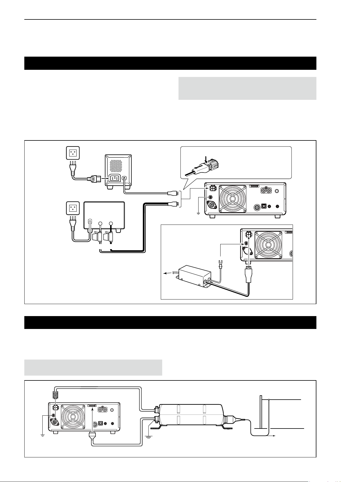
Connecting an external DC power supply
Conrm that the transceiver is OFF before connecting
the DC power cable.
L We recommend using Icom’s optional PS-126
(DC 13.8 V/25 A) power supply.
L When connecting a non-Icom DC power cable, the
transceiver needs:
• DC 13.8 V (Capacity: At least 21 Amps)
• A power supply with an over current protective line and
low voltage uctuation or ripple.
PS-126
AC cable
PS-126
DC power cable
Non-Icom DC power supply
DC 13.8 V/21 A
or more
_+
Fuses
CAUTION:
of the transceiver after transmitting continuously for long
periods of time. The transceiver becomes extremely hot.
DO NOT touch the cooling fan on the rear panel
When disconnecting, rmly
q
w
GND
push down the locking tab
and then pull the connector
out of the socket.
IC-7300
For European versions
BlackRed
Supplied DC
power cable
Connecting the antenna tuner
The AH-4 matches the IC-7300 to
AH-2b or a long wire antenna more than 7 m/23 ft long
(between 3.5 MHz and 50 MHz).
NOTE: Before connecting, be sure to turn OFF the
transceiver power.
[ANT]
[TUNER]
the optional
Connect to
power supply
L See the AH-4 instruction manual for installation and
connection details.
HF band long wire
antenna
AH-4
GND
IC-7300
Control cable
GND
Or to an optional AH-2b
2-4
Page 21
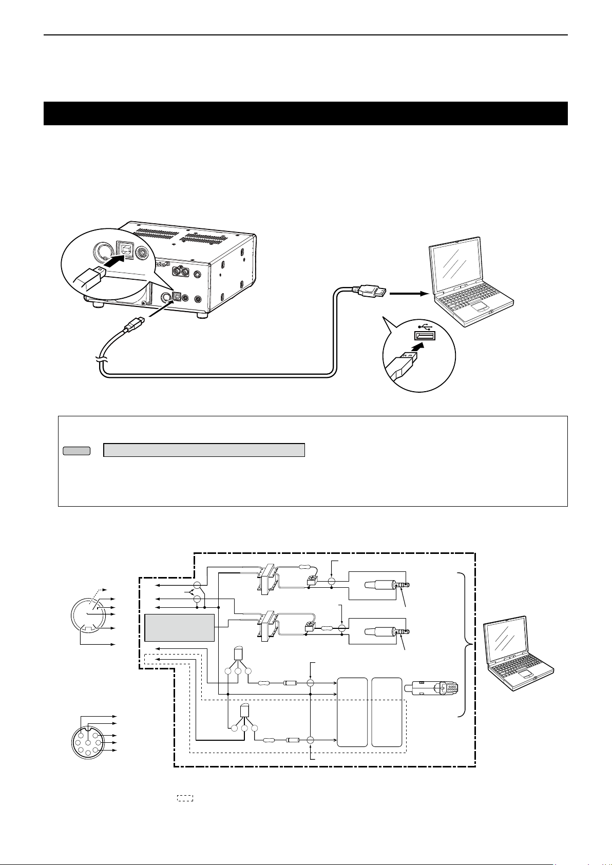
INSTALLATION AND CONNECTIONS
MENU
Previous view
2
FSK and AFSK connections
The transceiver has a mode key for RTTY. You can use a PC and an application software to operate RTTY using a
USB cable. However, if you want to operate RTTY or other digital modes, you can use the ACC socket on the rear
panel through an interface unit. Refer to the software application’s instruction manual for setup details.
( Icom does not guarantee performance of the application software, PC, network device or network settings.)
(1) When using the USB port
Type B
To a USB port
PC
To the
USB port
IC-7300
Install the RTTY
A user supplied A/B USB cable
Type A
application software
TIP:
• If you set the “USB Serial Function” item to “RTTY Decode,” the decoded RTTY signals are output from the USB port.
» SET > Connectors > USB Serial Function
• You can download the USB driver and the installation guide from the Icom website.
http://www.icom.co.jp/world/index.html
(Support > Firmware Updates/Software Downloads > Transceiver)
(2) When using the ACC socket or the microphone connector
• When connecting to [ACC]
ACC
o !0 !1 !2
t y u i
q w e r
(Rear panel view)
SQL
D
!3
E
A
B
C
E
Shield cable
D
C
• ACC: Connect to [C]
• MIC: Connect to [F]
B
A
• When connecting to [MIC]
D
E
1
7
2
3
4
(Front panel view)
NOTE: You can operate
ONLY AFSK RTTY when
you connect the circuit to
the microphone connector.
F
6
8
C
5
B
*1 NPN transistor
(2SC1815)
The sections shown in short dashes are required only when Baudot RTTY is used in the FSK (RTTY) mode.
(Not required for other digital modes such as SSTV or PSK)
2 kΩ:2 kΩ 10 kΩ
2 kΩ:2 kΩ
*1
CE B
4.7 kΩ
*1
CE B
4.7 kΩ
10 kΩ
(Trimpot)
Shield cable
10 kΩ
(Trimpot)
*2 Switching diode
(1S1588)
*2
*2
10 kΩ
Shield cable
RTS
GND
TXD
Shield cable
2-5
Shield cable
D-Sub 25
D-Sub 9
Pin 4
Pin 7
Pin 2 Pin 3
Connect to
LINE IN or
MIC IN
No connection
Connect to
SP OUT
No connection
Pin 7
Pin 5
Connect to
COM port
Interface circuit
example for digital
modes
(User supplied)
L See pages 18-2 to
18-3 for details on
the ACC socket and
MIC connector.
PC
Page 22
INSTALLATION AND CONNECTIONS
Previous view
2
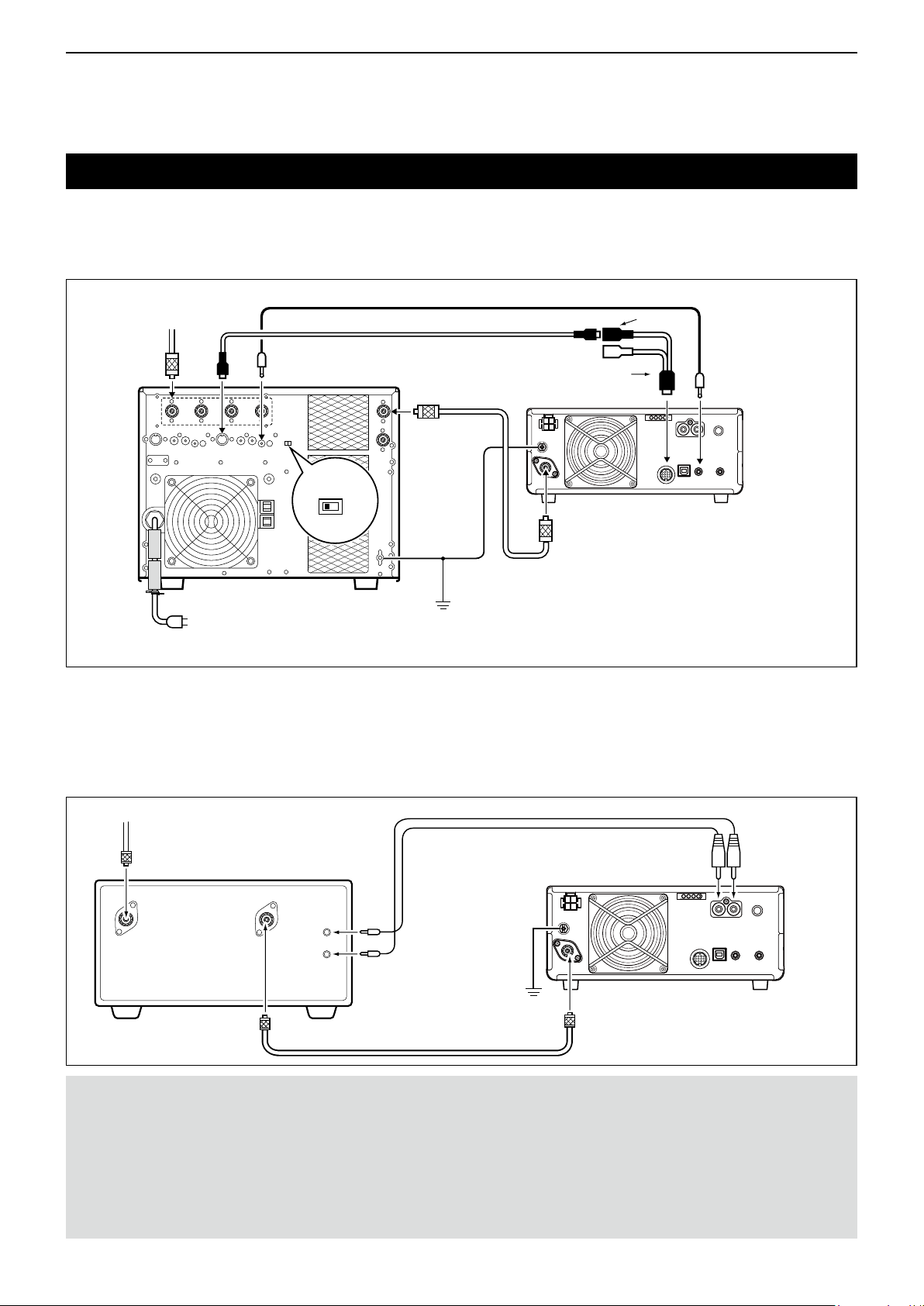
Linear amplier connections
D Connecting the IC-PW1/IC-PW1EURO
See the illustration below to connect the optional IC-PW1 or IC-PW1EURO hf/50 mhz all band 1 kw linear amplifier.
Refer to the amplier’s instruction manual for operation.
To an
antenna
[ACC-1]
[REMOTE][ANT]
EXCITER
1 1&2
IC-PW1/IC-PW1EURO
AC outlet
Non-European versions: 100~120/200~240 V
European version: 230 V
Remote control cable
ACC cable
[INPUT 1]
OPC-599 conversion cable
Coaxial cable
GND
[ANT]
GND
7-pin side
[ACC]
IC-7300
[REMOTE]
D Connecting a non-Icom linear amplier
See the illustration below to connect a non-Icom linear amplier.
L We recommend that you use a linear amplier with a specied input power of 100 watts or more. If you use an
amplier with a specied drive level of less than 100 watts, adjust the IC-7300’s output power to the specied
level before transmitting. Otherwise the linear amplier may be damaged.
To an antenna
Non-Icom linear amplier
RF OUT RF IN
ALC
SEND
GND
[ANT]
[ALC] [SEND]
IC-7300
R WARNING!
• The maximum signal level of the [SEND] jack is 16 V/0.5 A DC. Use an external unit if your non-Icom linear amplier requires
a control voltage and/or current greater than specied.
• The ALC input level must be in the range 0 to –4 V. The transceiver does not accept a positive voltage. Non-matched ALC
and RF power settings could overheat or damage the linear amplier.
• When using a linear amplier such as the IC-PW1 or IC-PW1EURO, set the RF POWER in the Multi-function menu to keep
the ALC meter in the red zone.
LSee page 3-10 for details on the RF POWER
LSee page 3-11 for details on the ALC zone.
2-6
Page 23

Section 3
Previous view
BASIC OPERATION
When rst applying power ...................................................... 3-2
Turning power ON or OFF ...................................................... 3-2
Adjusting the volume level ...................................................... 3-2
About the VFO and Memory modes ....................................... 3-2
Using the VFO mode .............................................................. 3-2
D Selecting VFO A or VFO B .............................................. 3-2
D Equalizing VFO A and VFO B ......................................... 3-2
Selecting the operating band .................................................. 3-3
D Using the band stacking registers ................................... 3-3
Selecting the operating mode ................................................. 3-3
Setting the frequency.............................................................. 3-4
D Using the Main Dial ......................................................... 3-4
D About the Tuning Step function ....................................... 3-4
D Changing the Tuning Step .............................................. 3-4
D About the 1 Hz step Fine Tuning function ....................... 3-4
D About the 1/4 Tuning function ......................................... 3-5
D About the Auto Tuning Step function .............................. 3-5
D Directly entering a frequency .......................................... 3-5
D Band Edge Beep ............................................................. 3-6
D Entering a Band Edge ..................................................... 3-7
RF gain and SQL level ......................................................... 3-10
Dial Lock function ................................................................. 3-10
Basic transmission................................................................ 3-10
Adjusting the transmit output power ..................................... 3-10
D Adjusting the transmit output power ............................. 3-10
Meter display .........................................................................3-11
D Meter display selection ..................................................3-11
D Multi-function meter .......................................................3-11
Adjusting the microphone gain ..............................................3-11
About the 5 MHz frequency band
operation (USA version only) ............................................ 3-12
3-1
Page 24
3
AF RF/SQL
POWER
POWER
AF RF/SQL
MAIN DIAL
V/M
A/B
A/B
V/M
A/B
Previous view
BASIC OPERATION
When rst applying power
Before turning ON your transceiver for the rst time,
make sure all of the following are correctly connected.
• DC power cable
• Antenna
• Grounding wire
• Microphone*
* Different devices may be used, depending on the
operating mode.
If all listed above are correctly connected, set
(inner/outer) to the positions described
below.
12 oʼclock position (outer)
Maximum counterclockwise (inner)
TIP: When you turn OFF the transceiver, it memorizes
the current settings. Therefore, when you turn ON the
transceiver again, the it restarts with the same settings.
Turning power ON or OFF
z To turn ON the transceiver, push
z To turn OFF the transceiver, hold down
2 seconds until “POWER OFF...” is displayed.
.
for
About the VFO and Memory modes
VFO mode
You can set the desired frequency by rotating
Memory mode
You can enter contents into the memory channels in
the MEMORY list.
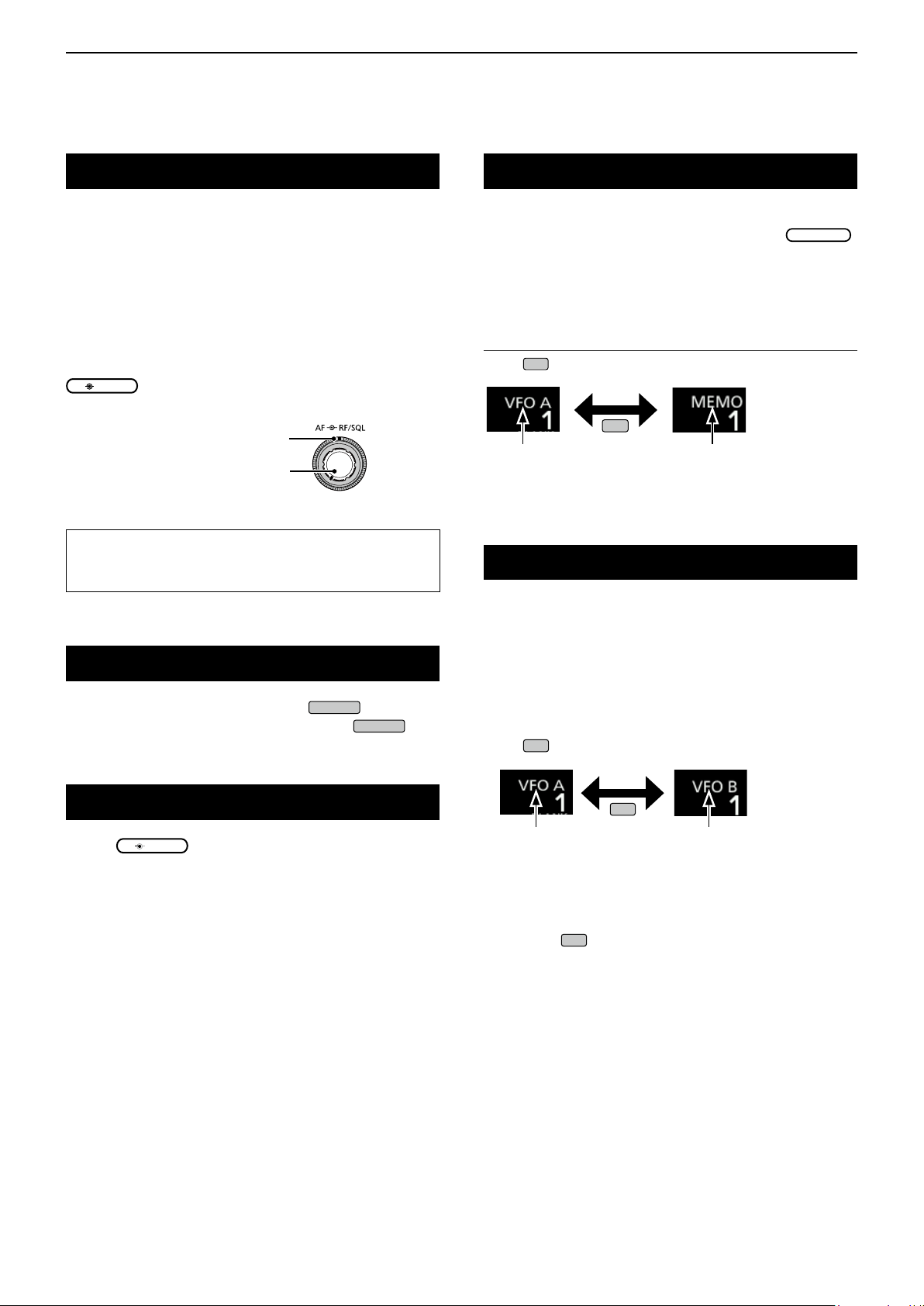
Selecting the VFO mode or Memory mode
Push
VFO mode
(Example: VFO A)
to select the VFO or Memory mode.
Memory mode
(Example: Memory channel 1)
Using the VFO mode
The IC-7300 has 2 Variable Frequency Oscillators
(VFO), “A” and “B.” Having 2 VFOs is convenient to
quickly select 2 frequencies, or for split frequency
operation (p. 4-13). You can use either of the VFOs to
operate on a frequency and mode.
D Selecting VFO A or VFO B
Push
to select the VFO A or VFO B.
.
Adjusting the volume level
Rotate
(inner) to adjust the volume level.
VFO A VFO B
D Equalizing VFO A and VFO B
You can set the displayed VFO’s frequency and mode
to the VFO that is not displayed.
Hold down
until 2 short beeps sound.
3-2
Page 25
3
MENU
Previous view
BASIC OPERATION
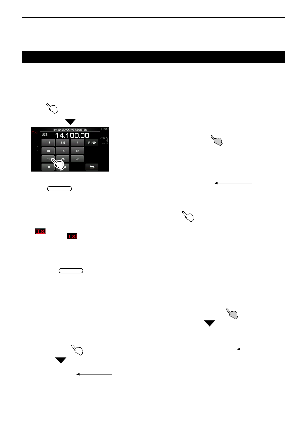
Selecting the operating band
Do the following steps to change the operating band.
Also, the band stacking register provides 3 memories
for each band key to store frequencies and operating
modes. This function is convenient to quickly recall
previously operated frequencies and modes.
D Using the band stacking registers
Follow the steps below to enter a register on the
selected band. (Example: Memorizing 21 MHz)
1. Touch the MHz digits. (Example: 14)
• Opens the BAND STACKING REGISTER screen.
2. Touch a band key. (Example: [21])
BAND STACKING REGISTER screen
• Displays a 21 MHz frequency.
TIP: Selecting a different Register
L Touching the band key for 1 second changes between
the 3 Registers.
LTouch
3. Set the frequency and the operating mode.
(Example: 21.30000 MHz in the USB mode)
to return to the previous screen.
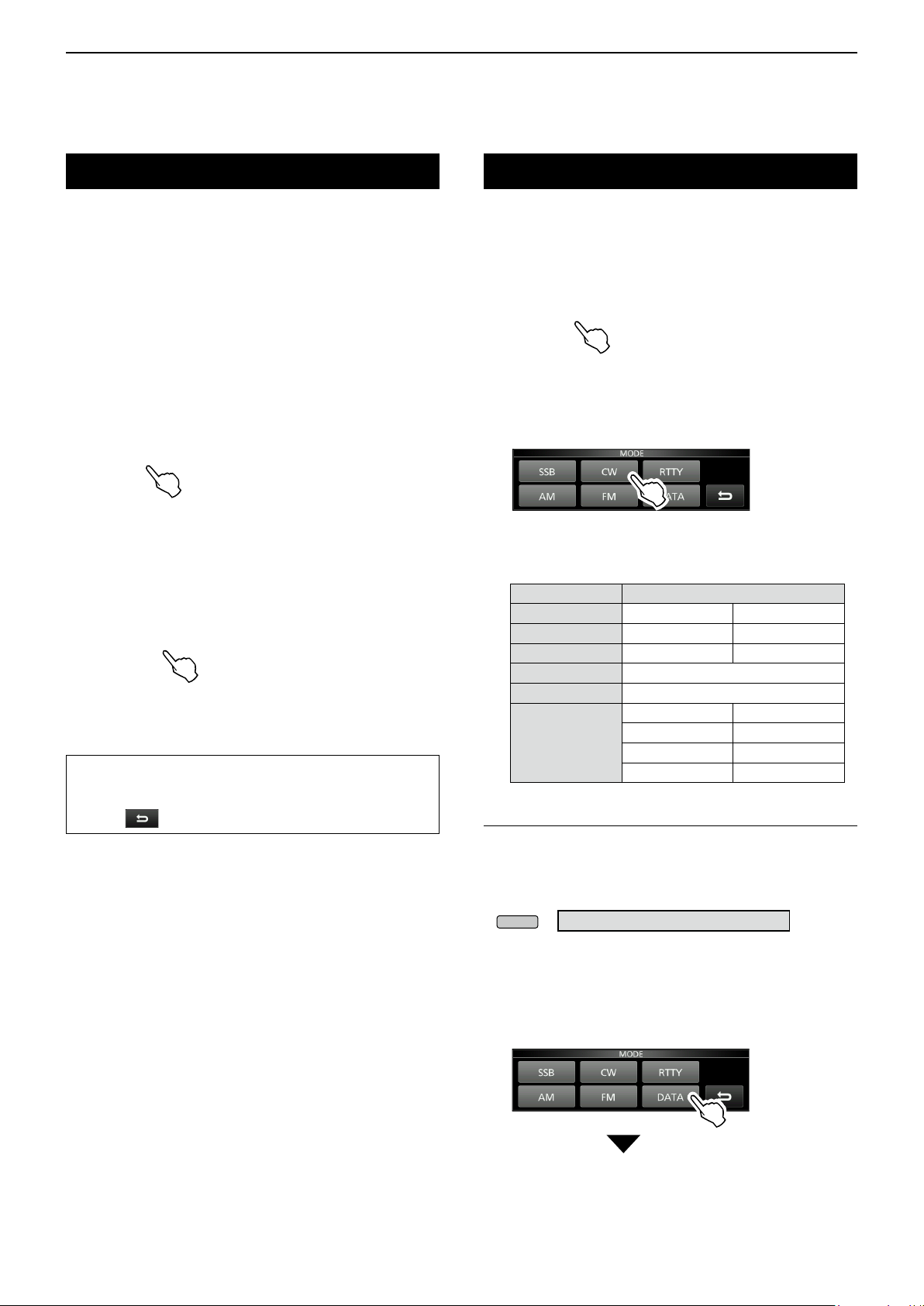
Selecting the operating mode
You can select between the SSB, SSB data, CW, CW
reverse, RTTY, RTTY reverse, AM, AM data, FM and
FM data modes.
1. Touch the mode icon (example: USB).
2. In the MODE screen, touch the desired mode key.
(Example: CW).
L In the SSB, AM or FM modes, the [DATA] key is
displayed.
MODE screen
• Operating mode selection list
LTouch mode key to select the operating mode
Mode key Operating mode
[SSB] LSB USB
[CW] CW CW-R
[RTTY] RTTY RTTY-R
[AM] AM
[FM] FM
LSB LSB-D
[DATA]
Selecting the Data mode
You can operate RTTY in the data mode using AFSK
(Audio Frequency Shift Keying). (p. 4-31)
L When a data mode is selected, you can mute the input
from the microphone. (p. 12-8)
» SET > Connectors > DATA MOD
USB USB-D
AM AM-D
FM FM-D
4. Touch the MHz digits again.
5. By repeating the steps above, the Register that a
L The frequency and operating mode set in step 3 is
memorized in the top Register.
new frequency and operating mode are set in is
memorized.
(Example: selecting the USB-D mode)
1. While the USB mode is selected, touch the mode
icon.
• Opens the MODE screen.
2. Touch [DATA].
MODE screen
• The USB-D mode is selected.
3-3
Page 26
3
MAIN DIAL
MAIN DIAL
Previous view
BASIC OPERATION
Setting the frequency
D Using the Main Dial
1. Select the desired operating band.
(Example: 21 MHz)
BAND STACKING REGISTER screen
2. Rotate
L If you cannot change the frequency, make sure the
Dial Lock function is turned OFF. (p. 3-10)
L
is displayed when you set an amateur radio
frequency, and
frequency outside the Ham band, or outside your set
Band Edges.
.
is displayed when you set a
D About the Tuning Step function
You can set the
operating mode. The following steps are set as
default.
• SSB/CW/RTTY (TS OFF): 10 Hz
• AM (TS ON): 1 kHz
• FM (TS ON): 10 kHz
Touch the kHz digits to turn the Tuning Step function
ON or OFF.
L The Tuning Step function's icon “▼” is displayed above
the 1 kHz digit.
’s tuning step for each
D Changing the Tuning Step
When the Tuning Step function is ON, you can change
the tuning steps for each operating mode.
1. Select the desired operating mode. (p. 3-3)
(Example: USB)
2. Touch the kHz digit for 1 second.
• The TS (SSB) screen is displayed.
3. Touch the desired tuning step.
(Example: 0.1 k)
• The tuning step is set and returns to the previous
screen.
The Tuning
Step function is
ON.
TS (SSB) screen
D About the 1 Hz step Fine Tuning
function
You can use the minimum tuning step of 1 Hz for ne
tuning in the SSB, CW and RTTY modes.
Touch the Hz digits for 1 second to turn the Fine
Tuning function ON or OFF.
• The 1 Hz digit is displayed.
The Tuning Step
function is ON.
1Hz digit
L When using the [UP]/[DN] keys on the microphone,
the frequency changes in 50 Hz steps with the Fine
Tuning function ON or OFF.
3-4
Page 27
3
FUNCTION
EXIT
MAIN DIAL
EXIT
MAIN DIAL
MENU
Previous view
BASIC OPERATION
Setting the frequency (Continued)
D About the 1/4 Tuning function
Mode: SSB-D/CW/RTTY
With the Tuning Function OFF, turn ON the 1⁄4 Tuning
function to reduce the tuning speed to 1⁄4 of the
normal speed, for ner tuning.
1. Push
• Opens the FUNCTION screen.
2. Touch [1/4].
FUNCTION screen
3. Push
.
.
1/4 Tuning
function
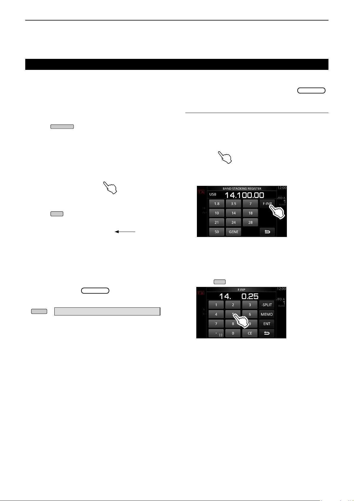
D Directly entering a frequency
You can set the frequency without rotating
by directly entering it on the keypad.
Entering the operating frequency
1. Touch the MHz digits.
(Example: 14)
• Opens the BAND STACKING REGISTER screen.
2. Touch [F-INP].
BAND STACKING REGISTER screen
• Opens the F-INP screen.
D About the Auto Tuning Step function
The tuning step automatically changes, depending on
the rotation speed of
L You can change the Auto Tuning Step function settings in
the following menu. (p. 12-6)
» SET > Function > MAIN DIAL Auto TS
.
3. Start entry with the MHz digits.
LTo clear the entry, touch [CE].
L To clear the entry and return to the previous screen,
push
F-INP screen (Example:14.025)
.
4. Touch [ENT] to set the entered frequency.
• Closes the F-INP screen.
L If you touch [ENT] when the digits under 100 kHz are
not entered, “0” will be automatically entered into the
digits that are blank.
Entry examples
• 14.025 MHz: [1], [4], [•(−)], [0], [2], [5], [ENT]
• 18.0725 MHz: [1], [8], [•(−)], [0], [7], [2], [5], [ENT]
• 730 kHz: [0], [•(−)], [7], [3], [ENT]
• 5.100 MHz: [5], [•(−)], [1], [ENT]
• 7.000 MHz: [7], [ENT]
• Changing from 21.280 MHz to 21.245 MHz:
[•(−)], [2], [4], [5], [ENT]
3-5
Page 28
3
V/M
V/M
MENU
Previous view
BASIC OPERATION
Setting the frequency (Continued)
Entering the Split Frequency Offset
1. Touch the MHz digits.
(Example: 14)
• Opens the BAND STACKING REGISTER screen.
2. Touch [F-INP].
BAND STACKING REGISTER screen
• Opens the F-INP screen.
3. Enter the Split Frequency Offset.
LIf you want the minus shift direction, touch [•(−)].
L Enter the offset between −9.999 MHz and +9.999
MHz (1 kHz steps).
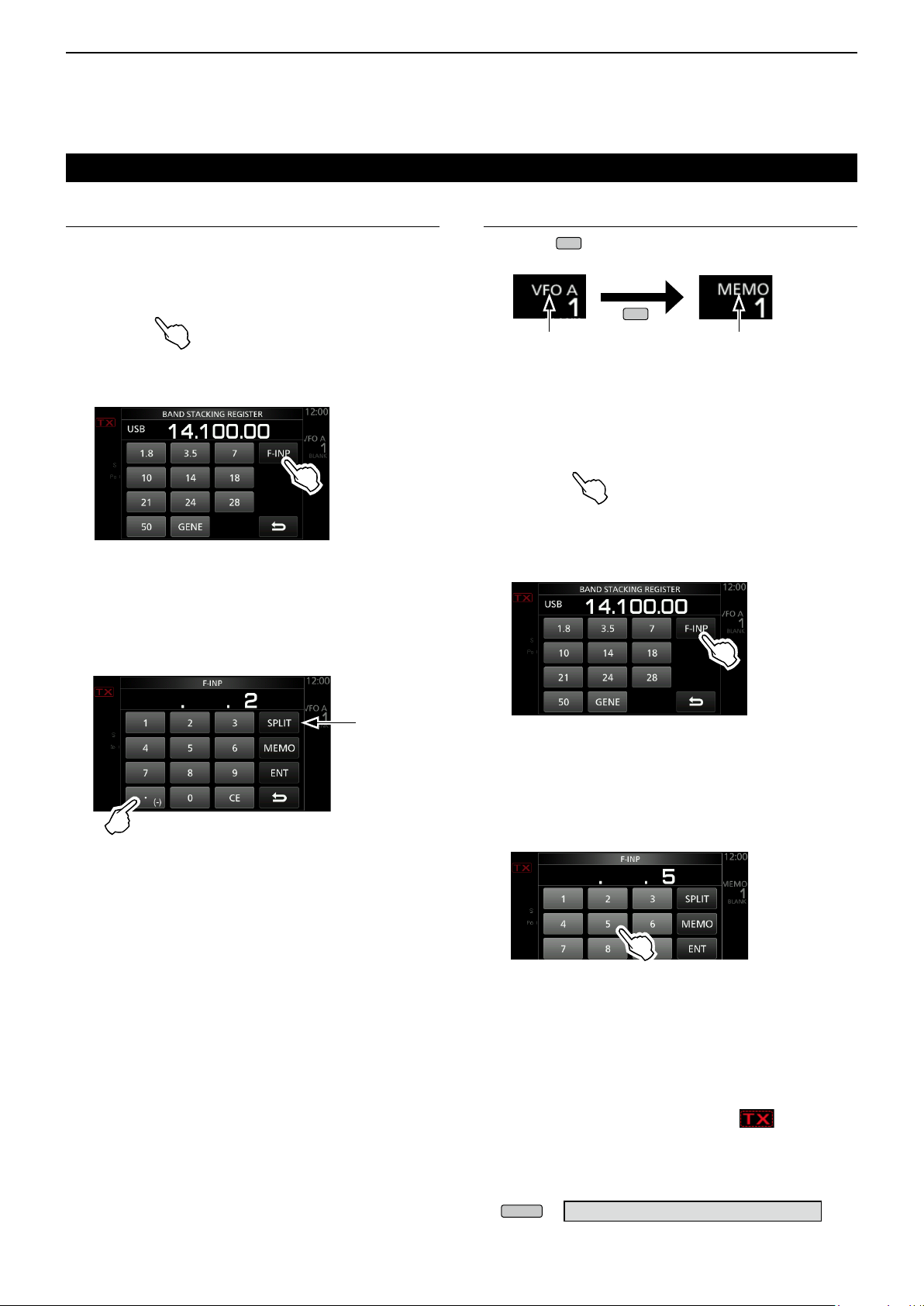
Entering a Memory channel
1. Touch
VFO mode
(Example: VFO A)
to select the Memory mode.
Memory mode
(Example: Memory channel 1)
2. Touch the MHz digits.
(Example: 14)
• Opens the BAND STACKING REGISTER screen.
3. Touch [F-INP].
[SPLIT] or
[-SPLIT] is
displayed
F-INP screen
Touch for -Split
4. To save the entry, touch [SPLIT] or [−SPLIT].
• Closes the F-INP screen.
Entry examples
• 10 kHz: [1], [0], [SPLIT]
• −1.025 MHz: [•(−)], [1], [0], [2], [5], [−SPLIT]
L After entering, the Split function is automatically turned
ON.
BAND STACKING REGISTER screen
• Opens the F-INP screen.
4. Enter a Memory channel number between 1 and
99. (Memory channel 5)
L If you want to set the Program Channel number (P1
or P2), enter “100” for P1, and “101” for P2.
F-INP screen
5. Touch [MEMO] to select the entered channel.
• Closes the F-INP screen.
D Band Edge Beep
You will hear a Band Edge Beep and will be
displayed when you tune into or out of an amateur
band’s frequency range.
L You can change the Band Edge Beep settings in the
following menu.
» SET > Function > Band Edge Beep
3-6
Page 29
3
MENU
MAIN DIAL
MULTI
Previous view
BASIC OPERATION
Setting the frequency (Continued)
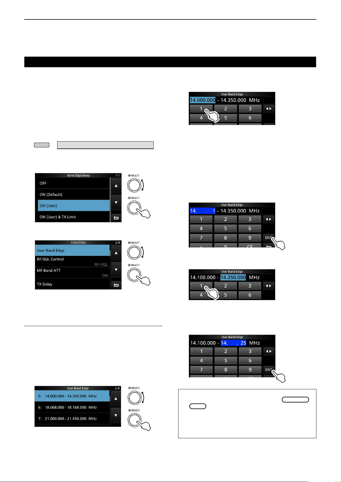
D Entering a Band Edge
When “ON (User)” or “ON (User) & TX Limit” is
selected on the “Band Edge Beep” screen, you can
enter a total of 30 band edge frequencies.
L Initially, all band edges are entered. Therefore, you must
rst edit or delete them to enter a new band edge.
L You cannot enter an overlapped frequency or a frequency
that is out of the preset transmit frequency.
1. Open the “Band Edge Beep” screen.
» SET > Function > Band Edge Beep
2. Select “ON (User)” or “ON (User) & TX Limit.”
L If you select “ON (User) & TX Limit,” you can limit
transmission to within the entered frequency range.
Rotate
Push
“Band Edge Beep” screen
3. Select “User Band Edge.”
3. Edit the lower band edge frequency.
(Example: 14.1)
Entry examples
• 14.025 MHz: [1], [4], [•], [0], [2], [5], [ENT]
• 18.0725 MHz: [1], [8], [•], [0], [7], [2], [5], [ENT]
• 730 kHz: [0], [•], [7], [3], [ENT]
• 5.100 MHz: [5], [•], [1], [ENT]
• 7.000 MHz: [7], [ENT]
• Changing from 21.280 MHz to 21.245 MHz:
[•], [2], [4], [5], [ENT]
4. Touch [ENT] to save the edited lower band edge
frequency.
Rotate
Push
FUNCTION set screen
• Opens the “User Band Edge” screen.
Editing a Band Edge
You can edit a band edge entered as a default or
when entering a new band edge.
1. On the FUNCTION set screen, select “User Band
Edge.”
2. Touch the band edge you want to edit for 1
second.
(Example: 5: 14.000.000 – 14.350.000 MHz)
Rotate
Push
“User Band Edge” screen
5. Edit the upper band edge frequency.
(Example: 14.25)
6. Touch [ENT] to save the edited upper band edge
frequency.
L The edited band edge is saved and returns to the
previous screen.
TIP:
• You can also edit the frequency by rotating
or
• Each band edge must be higher in frequency than the
ones above it. If you try to enter a lower frequency than
the edges above, the lower frequency edge will be
cleared when you push [ENT].
.
3-7
Page 30
3
Rotate
Previous view
BASIC OPERATION
Setting the frequency
D Entering a Band Edge (Continued)
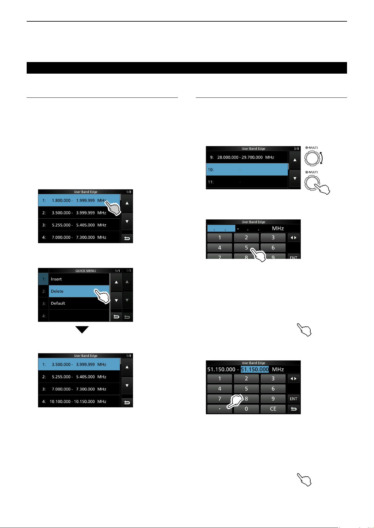
Deleting a Band Edge
To enter a new band edge, rst you must delete a
preset band edge.
L Initially, all band edges are entered. Therefore, you must
rst edit or delete them to enter a new band edge.
L You cannot enter an overlapped frequency or a frequency
that is out of the preset transmit frequency.
1. On the FUNCTION set screen, select “User Band
Edge.”
2. Touch the desired band edge to delete for 1
second.
(Example: 1: 1.800.000 – 1.999.999 MHz)
“User Band Edge” screen
3. Touch “Delete.”
Entering a new Band Edge
After you delete or edit the preset band edges, you
can enter a new band edge.
1. Open the “User Band Edge” screen.
2. Select a blank band.
(Example: 10)
Push
“User Band Edge” screen
3. Enter the lower band edge frequency.
(Example: 51.15)
4. Touch [ENT] to save the entered lower band edge
frequency.
• The selected band edge is deleted and returns to the
previous screen.
1.800.000 – 1.999.999 MHz is deleted.
5. Enter the upper band edge frequency.
(Example: .75)
6. Touch [ENT] to save the entered upper band edge
frequency.
• The entered band edge is saved and returns to the
previous screen.
3-8
Page 31

3
Previous view
BASIC OPERATION
Setting the frequency
D Entering a Band Edge (Continued)
Inserting a Band Edge
After you delete or edit the preset band edges, follow
the steps below to insert a band edge.
L Initially, all band edges are entered. Therefore, you must
rst edit or delete them to enter a new band edge.
L You cannot enter an overlapped frequency or a frequency
that is out of the preset transmit frequency.
1. Open the “User Band Edge” screen.
2. Touch the band edge you want to insert a new
band edge above for 1 second.
(Example: 1: 3.500.000–3.999.999 MHz)
L The new band edge will be inserted above the
selected band edge.
7. Touch [ENT] to save the entered upper band edge
frequency.
• The entered band edge is saved and returns to the
previous screen.
Resetting all band edges to presets
The steps below will reset all the band edges to their
initial settings. All entered settings will be deleted.
“User Band Edge” screen
3. Touch “Insert.”
4. Enter the lower band edge frequency.
(Example: 1.85)
5. Touch [ENT] to save the entered lower band edge
frequency.
1. Open the “User Band Edge” screen.
2. Touch any band edge for 1 second.
“User Band Edge” screen
3. Touch “Default.”
• Displays “Reset All Edges?”
4. Touch [YES].
• All the band edges reset to the initial settings.
6. Enter the upper band edge frequency. (Example: .95)
3-9
Page 32

3
AF RF/SQL
AF RF/SQL
AF RF/SQL
AF RF/SQL
AF RF/SQL
MENU
MAIN DIAL
Lights red
TRANSMIT
TRANSMIT
SPEECH
MENU
TRANSMIT
TRANSMIT
Previous view
BASIC OPERATION
RF gain and SQL level
Rotate
SQL level.
By default, rotating to left (when set to the 12 o’clock
position) adjusts the RF gain, and rotating to right
adjusts the squelch level as described below.
Squelch is open
RF gain
adjustable range
is displayed
Minimum RF gain
RF gain
Adjust the RF gain to decrease the noise received
from a nearby strong station.
• Rotate counterclockwise to reduce the RF gain, which
reduces the receive sensitivity. “RFG” appears when
position. “RFG” indicates that the RF gain is reduced.
L If a strong signal is received and “OVF” (Overow)
appears, reduce the RF gain until “OVF” disappears.
(outer) to adjust the RF gain and
Noise squelch (FM mode)
Maximum RF gain
S-meter squelch
adjustable range
Maximum S-meter
squelch
is set to the counterclockwise from the 11 o’clock
Basic transmission
1. Push
• The TX/RX indicator lights red and is displayed
while transmitting.
2. Push
• Returns to receive.
or [PTT] to transmit.
or release [PTT].
Adjusting the transmit output power
Before transmitting, monitor your selected operating
frequency to make sure you do not cause interference to
other stations on the same frequency. It is good amateur
practice to listen rst, and then, even if nothing is heard,
ask if the frequency in use once or twice, before you start
operating.
D Adjusting the transmit output power
1. Set the operating mode to SSB, CW, RTTY or FM.
(p. 3-3)
(Example: USB)
2. Touch the meter to display the Po meter. (p. 3-11)
3. Open the Multi-function menu.
SQL level
There are 2 types of SQL levels, depending on the
operating mode.
• Noise squelch
Rotate the
disappears and the TX/RX indicator goes OFF.
(outer) until the noise just
• S-meter squelch
The S-meter squelch mutes the audio output from the
speaker or headphones when the received signal is
weaker than the specied S-meter squelch level.
Rotate the
position to increase the S-meter threshold level.
L You can change the
“RF/SQL Control.” (p. 12-4)
clockwise from the 12 o’clock
(outer) control type in
» SET > Function > RF/SQL Control
Dial Lock function
The Dial Lock function prevents frequency changes
caused by accidently moving
LThis function electronically locks the dial.
.
Push
4. Push
• The Po meter level changes according
to your voice level in the SSB mode.
• The TX/RX indicator lights red and
is displayed.
L Tune the antenna before you view the power meter
level on the meter. If the antenna is not tuned properly,
the meter will not reect the power level. (p. 11-2)
or hold down [PTT].
5. Touch “RF POWER.”
6. Adjust the transmit output power to between 0 and
100%.
Rotate
Push
Po meter
Hold down
Dial Lock function ON or OFF.
• “ ” is displayed while the function is ON.
• During Split Frequency operation, the Split
Lock function may be turned ON. (p. 12-6)
for 1 second to turn the
Hold down
» SET > Function > Lock Function
3-10
• The Po meter displays the RF output power in a
percentage. It becomes the S-meter while receiving.
7. Push
• Returns to receive.
or release [PTT].
Page 33

3
MULTI
TRANSMIT
MULTI
TRANSMIT
Previous view
BASIC OPERATION
Meter display
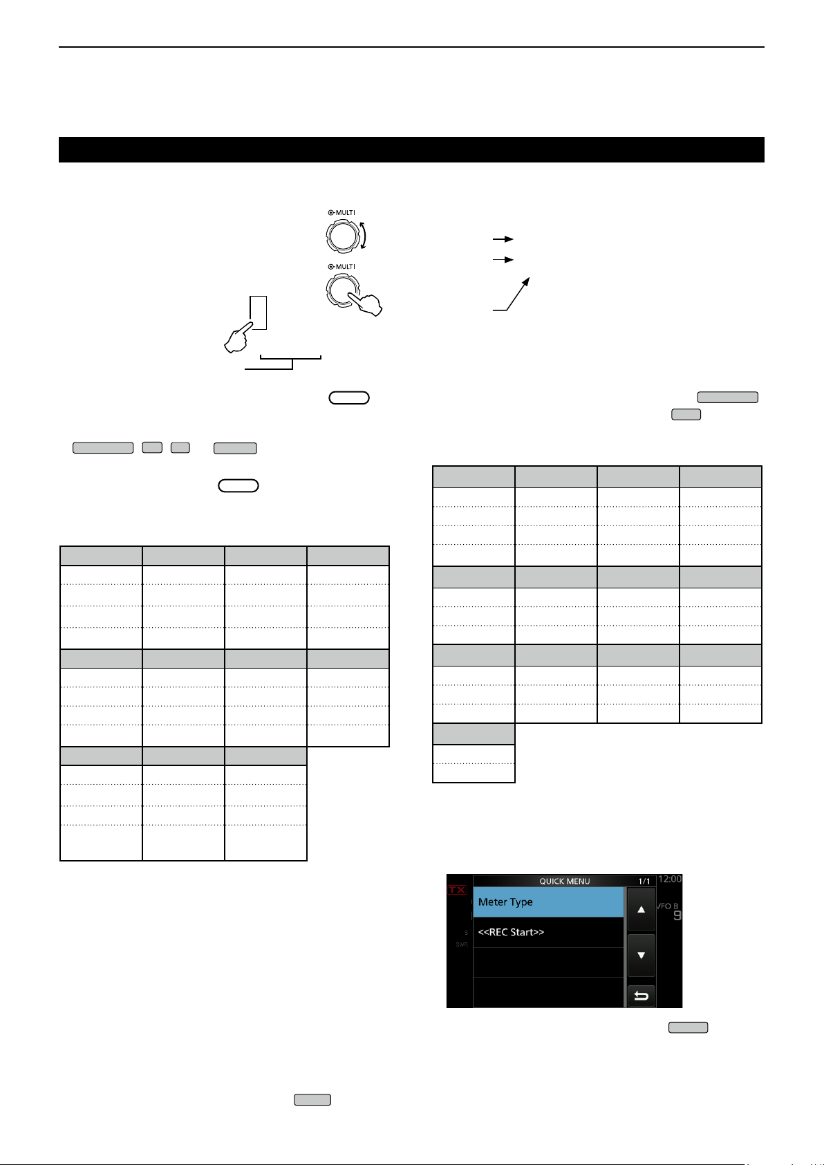
D Meter display selection
You can display one of the 6 different transmit
parameters (Po, SWR, ALC, COMP, VD and ID) for
your convenience.
Touch the parameter to display one of the meters.
D Multi-function meter
You can display all the parameters simultaneously.
L The power amplier temperature (TEMP) meter is also
displayed on the Multi-function meter.
Hold down the parameter for 1 second to display the
Multi-function meter.
ALC meter
ALC zone
Adjusting the microphone gain
Adjust the microphone gain as described below.
1. Set the operating mode to SSB, AM or FM.
(p. 3-3)
2. Push
3. Touch “MIC GAIN.”
4. Push
[PTT] on the microphone.
• The TX/RX indicator lights red and
is displayed.
InformationL
• In the SSB mode, touch the TX meter to select
the ALC meter and adjust until the meter reading
swings between 30 to 50% of the ALC scale.
• Hold the microphone 5 to 10 cm (2 to 4 inches)
from your mouth, then speak at your normal voice
level.
• In the AM or FM mode, check the audio clarity with
another station, or use the Monitor function (p. 4-11).
to display the Multi-function menu.
or hold down
Lights red
Multi-function meter
TX inhibit zone
Displays the drain
voltage of the nal
amplier MOS-FETs.
S: Displays the receiving signal strength level.
Po: Displays the relative RF output power.
SWR: Displays the SWR of the antenna at the
operating frequency.
ALC: Displays the ALC level. When the meter
movement shows the input signal level exceeds
the allowed level, the ALC limits the RF power.
In such cases, decrease the microphone gain
level.
COMP: Displays the compression level when the
speech compressor is used.
VD: Displays the drain voltage of the nal amplier
MOS-FETs.
ID: Displays the drain current of the nal amplier
MOS-FETs.
TEMP: Displays the temperature of the nal amplier
MOS-FETs.
Displays the temperature
of the nal amplier
MOS-FETs.
5. Rotate
6. Push
• Returns to receive
to adjust the microphone gain.
or release [PTT].
3-11
Page 34

3
Previous view
BASIC OPERATION
About the 5 MHz frequency band operation (USA version only)
Operation on the 5 MHz frequency band is allowed
on 5 discrete frequencies and you must adhere to the
following:
• The USB, USB Data, PSK, and CW modes.
• Maximum of 100 watts ERP (Effective Radiated
Power)
• Maximum 2.8 kHz bandwidth
It is your responsibility to set all controls so that
transmission in this frequency band meets the
stringent conditions under which amateur operations
may use these frequencies.
TIP: We recommend that you save these
frequencies, modes and lter settings into memory
channels, for easy recall.
NOTE: To assist you in operating within the rules specied
by the FCC, transmission is illegal on any frequencies
other than the ve shown in the tables below.
For the USB and USB data modes:
The FCC species center frequencies on the 5 MHz
frequency band. However, the transceiver displays
carrier frequency. Therefore, tune the transceiver
to 1.5 kHz below the specied FCC channel center
frequency.
Transceiver displayed
frequency
5.33050 MHz 5.33200 MHz
5.34650 MHz 5.34800 MHz
5.35700 MHz 5.35850 MHz
5.37150 MHz 5.37300 MHz
5.40350 MHz 5.40500 MHz
For the CW mode:
The transceiver displays the center frequency.
Therefore, tune the transceiver to the specied FCC
channel frequency when you operate in the CW mode.
Transceiver displayed
frequency
5.33200 MHz 5.33200 MHz
5.34800 MHz 5.34800 MHz
5.35850 MHz 5.35850 MHz
5.37300 MHz 5.37300 MHz
5.40500 MHz 5.40500 MHz
FCC channel center
frequency
FCC channel center
frequency
3-12
Page 35

Section 4 RECEIVING AND TRANSMITTING
Previous view
Convenient for receiving ......................................... 4-2
D All operating modes ........................................ 4-2
D SSB, CW, RTTY, and AM modes .................... 4-2
D SSB, AM and FM modes ................................4-2
D SSB-D, CW and RTTY modes ........................ 4-2
D CW mode ........................................................ 4-2
Convenient for transmitting..................................... 4-2
D SSB, AM and FM modes ................................4-2
D SSB mode ....................................................... 4-2
D CW mode ........................................................ 4-2
Preampliers........................................................... 4-3
Attenuator ............................................................... 4-3
RIT function ............................................................4-3
D RIT monitor function ........................................ 4-3
AGC function control .............................................. 4-4
D Selecting the AGC time constant
preset value .................................................... 4-4
D Setting the AGC time constant ........................ 4-4
Using the Twin PBT ................................................ 4-5
Selecting the IF lter ............................................... 4-6
Selecting the IF lter shape .................................... 4-6
IP Plus function .......................................................4-7
Noise Blanker ......................................................... 4-8
D Adjusting the NB level and time ...................... 4-8
Noise Reduction ..................................................... 4-9
D Adjusting the Noise Reduction level ............... 4-9
Notch Filter ............................................................. 4-9
D Auto Notch function ........................................ 4-9
D Manual Notch function .................................... 4-9
VOX function ........................................................ 4-10
D Adjusting the VOX function ........................... 4-10
D Turning ON the VOX function ....................... 4-10
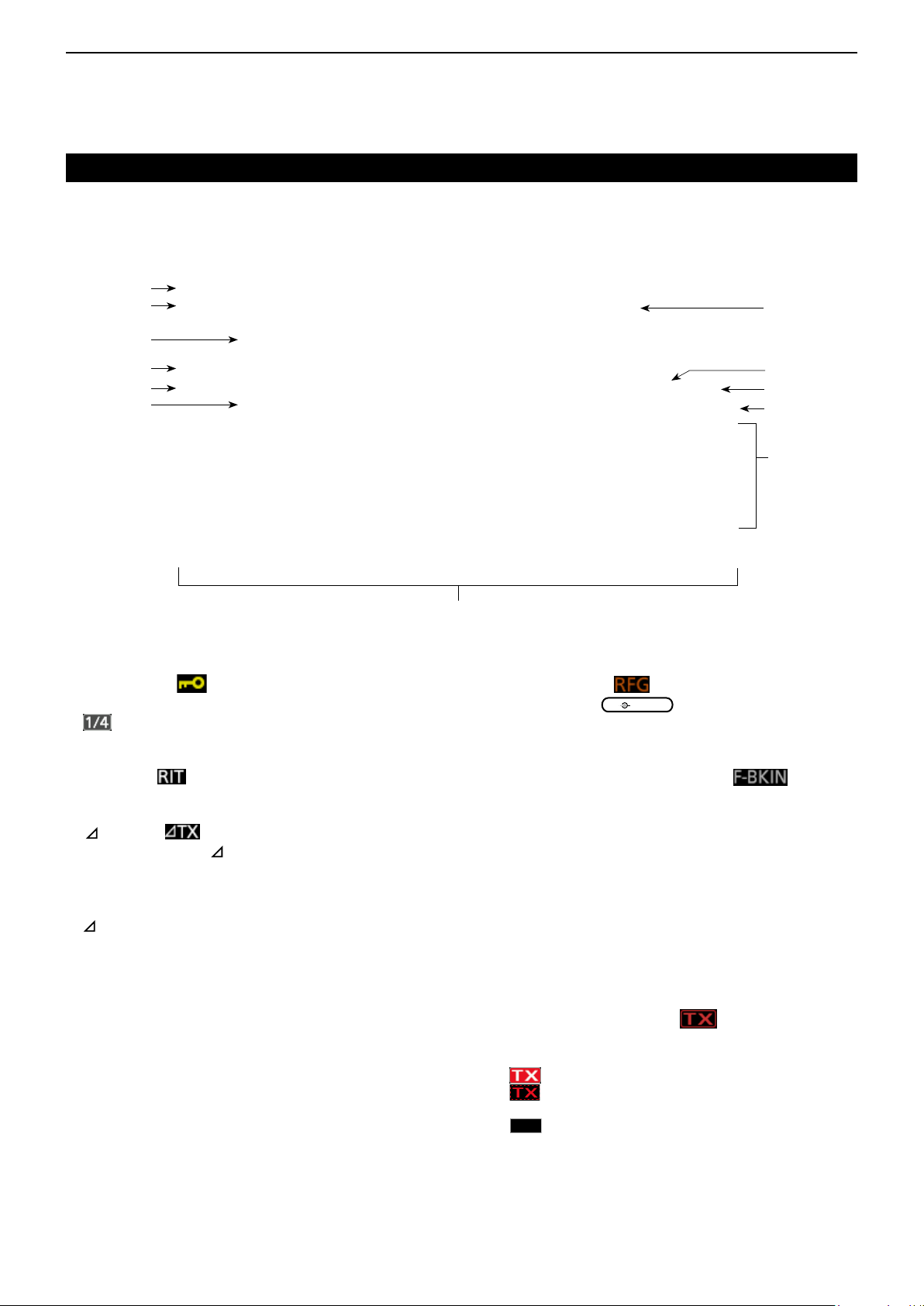
∂TX function ......................................................... 4-11
D ∂TX monitor function .................................... 4-11
Monitor function .................................................... 4-11
Setting the Speech Compressor........................... 4-12
Split frequency operation ...................................... 4-13
D Using the Quick Split function ....................... 4-13
D Using the receive and transmit frequencies
set to VFO A and VFO B ..............................4-13
Split Lock function ................................................ 4-14
Setting the transmit lter width ............................. 4-14
Operating CW ....................................................... 4-14
D Setting the CW pitch control ......................... 4-14
D Setting the key speed ................................... 4-15
D About the Break-in function .......................... 4-15
D CW Auto Tuning function .............................. 4-16
D About the CW Reverse mode ....................... 4-16
D Electronic Keyer function .............................. 4-17
D Monitoring the CW side tone ........................ 4-17
D Sending from the Memory keyer (KEYER) ... 4-18
D Keyer memory edit menu (EDIT) ................. 4-19
D Contest number menu (001 SET) ................. 4-20
D Keyer set menu (CW-KEY SET) ................... 4-21
Operating RTTY (FSK) ............................................ 4-22
D About the RTTY reverse mode ........................ 4-22
D Twin Peak Filter ............................................... 4-22
D Functions on the RTTY DECODE screen ........ 4-23
D Setting the decoder threshold level ................. 4-23
D Transmitting an RTTY memory content ........... 4-24
D Editing an RTTY memory ................................. 4-25
D Turning ON the RTTY log ............................... 4-26
D Viewing the RTTY log contents ........................ 4-26
D About the RTTY decode log set mode ............. 4-27
D About the RTTY decode set mode ................... 4-28
FM repeater operation ............................................. 4-29
D Setting the repeater tone frequency ................ 4-29
D Checking the repeater input signal .................. 4-30
Tone squelch operation ........................................... 4-30
Data mode (AFSK) operation .................................. 4-31
4-1
Page 36

RECEIVING AND TRANSMITTING
MENU
MENU
MENU
MENU
Previous view
4
Convenient for receiving
D All operating modes
Preampliers and Attenuator (p. 4-3)
Use one of the Preampliers when receiving weak
signals and use the Attenuator to prevent distortion
when receiving strong signals.
Notch Filter (p. 4-9)
Automatically attenuates beat tones, tuning signals,
and so on.
• In the SSB or AM mode:
Use the Auto notch or Manual notch.
• In the CW or RTTY mode:
Use the Manual notch.
• In the FM mode:
Use the Auto notch.
RX HPF/LPF (p. 12-3)
Sets the receive audio high-pass lter and low-pass
lter cutoff frequency in 100 Hz steps.
» SET > Tone Control/TBW > RX
D SSB, CW, RTTY, and AM modes
Noise Blanker (p. 4-8)
The Noise Blanker eliminates pulse-type noise.
Convenient for transmitting
D SSB, AM and FM modes
VOX function (p. 4-10)
The VOX (Voice-Operated Transmission) function
switches between transmit and receive with your
voice. This function provides hands-free operation.
Transmit Monitor (p. 4-11)
The Monitor function enables you to monitor your
transmit audio.
Audio Tone Control (p. 12-3)
You can adjust the transmit audio bass and treble.
» SET > Tone Control/TBW > TX
D SSB mode
Speech compressor (p. 4-12)
The speech compressor increases average RF output
power, improving signal strength and readability.
Transmitter Filter Width (p. 4-14)
You can select WIDE, MID, and NAR compression
bandwidths.
» SET > Tone Control/TBW > TX
Noise Reduction (p. 4-9)
The Noise Reduction function reduces random noise
components and enhances desired signals that are
buried in noise. The DSP (Digital Signal Processor)
does the random noise reduction.
AGC (p. 4-4)
The AGC (Auto Gain Control) controls the receiver
gain to produce a constant audio output level, even
when the received signal strength greatly varies.
Twin PBT (p. 4-5)
To reject interference, the Twin PBT (Passband Tuning)
electronically narrows the IF passband width by shifting
the IF frequency slightly outside of the IF lter passband.
D SSB, AM and FM modes
Receive Audio Tone Control (p. 12-3)
You can adjust the receive audio bass and treble.
» SET > Tone Control/TBW > RX
D SSB-D, CW and RTTY modes
1/4 function (p. 3-5)
The dial speed is reduced to 1⁄4 of the normal speed,
for ner tuning control.
D CW mode
Break-in function (p. 4-15)
You can use the Break-in function to automatically
switch the transceiver between transmit and receive
when keying. The IC-7300 is capable of Full Break-in
and Semi Break-in mode.
Auto Tuning (p. 4-16)
The transceiver automatically tunes the desired signal
within the ±500 Hz range.
D CW mode
4-2
Page 37

RECEIVING AND TRANSMITTING
P.AMP
ATT
P.AMP
ATT
P.AMP
ATT
RIT
RIT
CLEAR
RIT
RIT
Rotate
XFC
XFC
Previous view
4
Preampliers
The preamps amplify received signals in the receiver
front end to improve the signal-to-noise ratio and
sensitivity. A preamp is used when receiving weak
signals.
L Each band memorizes the Preamplier setting.
Push
L Each push changes between “P.AMP1,” “P.AMP2,” and
OFF (no icon).
Displayed when the preamp is ON.
(Example: P.AMP1)
P.AMP1
P.AMP2
NOTE: When you use the preamp while receiving
strong signals, the signal may be distorted. In such
case, turn OFF the preamp.
(P.AMP).
Wide dynamic range preamplier.
It is most effective for the HF low bands.
High-gain preamplier.
It is most effective for the 50 MHz bands.
RIT function
The RIT (Receive Increment Tuning) function
compensates for differences in frequencies of other
stations.
The function shifts the receive frequency up to ±9.99
without shifting the transmit frequency.
1. Push
• The RIT function turns ON.
L When using the Fine Tuning function (p. 3-4), the RIT
frequency is displayed in 4 digits, instead of 3.
LPushing
2. Set the RIT frequency to match the receiving
station’s frequency.
.
again turns OFF the RIT function.
RIT frequency
(3 digits)
Set RIT
frequency.
Attenuator
The Attenuator prevents a desired signal from
becoming distorted when a very strong signal is near
the frequency, or when a very strong electric eld,
such as from a broadcasting station, is near your
location.
LEach band memorizes the Attenuator setting.
Hold down
Attenuator.
LPushing
Displayed when the Attenuator is ON
(ATT) for 1 second to turn ON the
turns OFF the Attenuator (no icon).
L You can reset the RIT frequency to “0.00” by holding
down
L You can add the frequency shift to the operating
frequency by holding down
3. After communicating, push
for 1 second.
for 1 second.
to turn the RIT
function OFF.
D RIT monitor function
When the RIT function is ON, you can directly monitor
the operating frequency by holding down
L While monitoring, the RIT function is temporarily OFF.
L While monitoring, the settings for the Noise Reduction,
Notch lter and Twin PBT are temporarily OFF.
While holding down
.
.
4-3
Page 38

RECEIVING AND TRANSMITTING
FUNCTION
EXIT
FUNCTION
MAIN DIAL
EXIT
Previous view
4
AGC function control
The AGC (Automatic Gain Control) controls receiver
gain to produce a constant audio output level, even
when the received signal strength varies greatly.
D Selecting the AGC time constant
preset value
The transceiver has 3 preset AGC settings for all
modes except the FM mode. The time constants are
FAST, MID and SLOW.
1. Select the operating mode.
(Example: SSB)
2. Push
• Opens the FUNCTION screen.
3. Touch [AGC] to select the desired FAST, MID or
SLOW time constant.
LFor the FM mode, the FAST time constant is xed.
FUNCTION screen (SSB mode)
.
D Setting the AGC time constant
You can set the preset AGC time constant to a desired
value.
1. Select the operating mode.
(Example: SSB)
2. Push
• Opens the FUNCTION screen.
3. Touch [AGC] for 1 second.
FUNCTION screen (SSB mode)
• Opens the AGC (SSB) screen.
4. Touch either FAST, MID or SLOW to select the
desired AGC time constant.
(Example: MID)
AGC (SSB) screen (SSB mode)
.
You can
reset to the
default setting
by touching
this key for 1
second.
4. To close the FUNCTION screen,
.
5. Rotate
L The adjustable time constants are described in the
table below.
6. To close the AGC (SSB) screen, push
to set the time constant.
.
• Selectable AGC Time constant (unit: seconds)
Mode Default Adjustable time constant
0.3
(FAST)
2.0
SSB
CW/RTTY
AM
FM 0.1
NOTE: When you are receiving weak signals, and a strong
signal is momentarily received, the AGC function quickly
reduces the receiver gain. When that signal disappears,
the transceiver may not receive the weak signal because
of the AGC action. In that case, select FAST, or touch
[AGC] for 1 second to open the AGC screen, and then
select OFF the time constant setting.
(MID)
6.0
(SLOW)
0.1
(FAST)
0.5
(MID)
1.2
(SLOW)
3.0
(FAST)
5.0
(MID)
7.0
(SLOW)
(FAST)
OFF, 0.1, 0.2, 0.3, 0.5, 0.8, 1.2,
1.6, 2.0, 2.5, 3.0, 4.0, 5.0 or 6.0
OFF, 0.1, 0.2, 0.3, 0.5, 0.8, 1.2,
1.6, 2.0, 2.5, 3.0, 4.0, 5.0 or 6.0
OFF, 0.3, 0.5, 0.8, 1.2, 1.6, 2.0,
2.5, 3.0, 4.0, 5.0, 6.0, 7.0 or 8.0
Fixed
4-4
Page 39

RECEIVING AND TRANSMITTING
TWIN PBT
TWIN PBT
EXIT
TWIN PBT
TWIN PBT
TWIN PBT
TWIN PBT
Previous view
4
Using the Twin PBT
SSB, CW, RTTY and AM modes
In general, the Twin PBT (Passband Tuning)
electronically narrows the IF passband width by
shifting the IF frequency to slightly outside of the IF
lter passband, to reject interference. The IC-7300
uses DSP for the PBT function.
You can narrow the IF passband width by rotating
both
the opposite direction from each other.
L You can see the nearby signal using the Spectrum Scope
(Section 5).
CLR
inner (PBT1) and outer (PBT2) to
1. Rotate
CLR
inner (PBT1) and outer
(PBT2) to the opposite direction from each other.
InformationL
• Match both the
outer (PBT2) lters before operating the Twin PBT.
• Rejects interference of both higher and lower
passbands.
• If you rotate the control too much, the received
audio may not be heard because the passband
width is too narrow.
• Displays the passband width and shift value.
• A dot is displayed to the right of the passband width
when you rotate
• Hold down
PBT setting (the dot disappears).
• The PBT is adjustable in 50 Hz steps in the SSB,
CW, and RTTY modes, and 200 Hz in the AM
mode. In this case, the center shift value changes
in 25 Hz steps in the SSB, CW, and RTTY modes,
and 100 Hz in the AM mode.
• Rotating both the inner and outer controls to the
same position shifts the IF left or right.
CLR
(inner) (PBT1) and
CLR
.
CLR
for 1 second to clear the
2. Touch the Filter icon for 1 second to display the
current passband width and shift frequency.
• Opens the FILTER screen.
Passband
width
FILTER (SSB) screen (while operating Twin PBT)
PBT1
PBT2
3. To close the FILTER screen, push
NOTE: While rotating
This comes from the DSP unit and does not indicate an
equipment malfunction.
Shift
value
IF center frequency
Passband center frequency
SFT: Shift value
Passband width
BW:
.
CLR
, you may hear noise.
PBT is OFF
PBT2
PBT1
Cutting
lower passband
PBT2
PBT1
Passband
IF center frequency Interference Desired
signal
4-5
Cutting both higher and
lower passbands
PBT2
PBT1
Interference Desired
signal
Passband
Interference
Page 40

RECEIVING AND TRANSMITTING
MAIN DIAL
EXIT
EXIT
Previous view
4
Selecting the IF lter
The transceiver has 3 IF lter passband widths for each
mode, and you can select them on the FILTER screen.
You can set the IF lter to wide (FIL 1), mid (FIL 2) or
narrow (FIL 3).
1. Select the operating mode.
(Example: USB)
2. Touch the filter icon for 1 second.
• Opens the FILTER (SSB) screen.
3. Touch the filter icon more times to select FIL 1
(wide), FIL 2 (mid) or FIL 3 (narrow).
4. Touc h [ BW ].
• Selects the passband width mode.
L When you change the passband width, the Twin PBT
setting value is reset to the center position.
FILTER (SSB) screen (when FIL 2 is selected)
Mode IF lter Selectable range (steps)
SSB
SSB-D
CW
RTTY
AM
AM-D
FM
FM-D
FIL 1 (3.0 kHz)
FIL 2 (2.4 kHz)
FIL 3 (1.8 kHz)
FIL 1 (3.0 kHz)
FIL 2 (1.2 kHz)
FIL 3 (500 Hz)
FIL 1 (1.2 kHz)
FIL 2 (500 Hz)
FIL 3 (250 Hz)
FIL 1 (2.4 kHz)
FIL 2 (500 Hz)
FIL 3 (250 Hz)
FIL 1 (9.0 kHz)
FIL 3 (3.0 kHz)
FIL 1 (15 kHz)
FIL 3 (7.0 kHz)
50Hz to 500Hz (50 Hz)/
600Hz to 3.6kHz (100 Hz)
50Hz to 500Hz (50 Hz)/
600Hz to 3.6kHz (100 Hz)
50Hz to 500Hz (50 Hz)/
600Hz to 3.6kHz (100 Hz)
50Hz to 500Hz (50 Hz)
600Hz to 2.7kHz (100 Hz)
200Hz to 10.0kHz (200 Hz)FIL 2 (6.0 kHz)
FixedFIL 2 (10 kHz)
5. Rotate
L You cannot change the passband width in the FM or
FM-D mode.
Passband width mode
Displayed when a band width less than 500 Hz
is selected in the SSB or CW mode.
to adjust the passband width.
Touch [DEF]
for 1 second to
reset to default.
6. Touch [ B W ].
• Cancels the passband width mode.
7. Repeat steps 2 to 6 to set the passband width for
other modes except for the FM and FM-D.
8. To close the FILTER screen, push
TIP: When you set the IF lter to FIL2 or FIL3 in the FM
mode, the transceiver will transmit in the FM narrow mode.
.
Selecting the IF lter shape
You can independently set the DSP lter shape for
operating modes to soft or sharp.
1. Set the operating mode to SSB, SSB-D or CW.
(Example: USB)
2. Touch the filter icon for 1 second.
• Opens the FILTER screen.
3. Touch the filter icon several times to select FIL1
(wide), FIL2 (mid) or FIL3 (narrow).
4. Touch [SHARP] or [SOFT].
When [SOFT] is selected
5. To close the FILTER screen, push
.
4-6
Page 41

RECEIVING AND TRANSMITTING
FUNCTION
EXIT
Previous view
4
Selecting the IF lter shape (Continued)
• SHARP
This selection is to emphasize the passband width of
the lter. The lter has an almost ideal shape factor.
Signals of the out of passband are extremely ltered
out and it gives you better audio quality.
• SOFT
The lter shoulders are roundly formed as in analog
lters. This decreases noise components in the
high and low frequencies of the lter passband
and increases the S/N of the target signal. These
characteristics play an effective role in picking up
very weak signals in the 50 MHz band, for example.
The shape factor is kept, and the sharpness of the
bandpass is excellent.
IP Plus function
The IP Plus function improves the Intermodulation
Distortion (IMD) quality by exerting the direct sampling
system performance.
This function optimizes the Analog/Digital Converter
(ADC) against the distortion when you receive a
strong input signal. It also improves the Third-order
Intercept Point (IP3) while minimizing the reduction of
the receive sensitivity.
1. Push
• The FUNCTION screen is displayed.
2. Touch [IP+].
LTouch [IP+] to turn the IP Plus function ON or OFF.
L Select ON to prioritize the IP quality, and select OFF
to prioritize the receive sensitivity.
.
3. To close the FUNCTION screen, push
.
• “IP+” is displayed when ON is selected.
Displayed
4-7
Page 42

RECEIVING AND TRANSMITTING
Rotate
Previous view
4
Noise Blanker
The Noise blanker eliminates pulse-type noise such
as the noise from car ignitions.
The Noise blanker cannot be used in the FM mode.
Push NB to turn the Noise Blanker ON or OFF.
Displayed
NOTE: When using the Noise Blanker, received signals
may be distorted if they are excessively strong or the noise
is other than a pulse type. In that case, turn OFF the Noise
Blanker, or shallow the DEPTH on the NB menu.
See the description below for details.
D Adjusting the NB level and time
To deal with various type of noise, you can adjust the
attenuation level and noise width in the NB menu.
1. Hold down NB for 1 second.
• Turns ON the Noise Blanker and opens the NB menu.
2. Touch the adjusting item.
(Example: DEPTH)
3. Adjust the level.
(Example: 8)
LEVEL (Default: 50%)
Adjust the level where the Noise Blanker activates
between 0 and 100%.
DEPTH (Default: 8)
Adjust the noise attenuation level to between 1 and
10.
WIDTH (Default: 50)
Adjust the blanking duration time to between 1 and
100.
Noise Blanker OFF Noise Blanker ON
Pulse-type
noise
Receive
signal
Noise Blanker ON
(Not enough DEPTH)
Pulse-type
noise remains
Receive
signal
LEVEL
Receive
signal
NB WIDTH
Noise Blanker ON
(WIDTH set too long)
Pulse-type
noise eliminated
Receive signal is
eliminated along with
pulse-type noise
Receive
signal
Push
4-8
Page 43

RECEIVING AND TRANSMITTING
Rotate
NOTCH
NOTCH
NOTCH
Previous view
4
Noise Reduction
The Noise Reduction function reduces random noise
components and enhances desired signals that are
buried in noise. The Noise Reduction function uses
the DSP circuit.
Push NR to turn the Noise Reduction function ON or
OFF.
Displayed
D Adjusting the Noise Reduction level
Adjust the Noise Reduction level to where noise is
reduced and the received signal is not distorted.
1. Hold down NR for 1 second.
• Turns ON the Noise Reduction function and opens the
NR menu.
2. Adjust the Noise Reduction level to between 0
and 15.
L Adjust to a higher level to increase the reduction
level, and a lower level to decrease it.
Notch Filter
The IC-7300 has Auto Notch and Manual Notch
functions.
Auto Notch: Used in the SSB, AM and FM modes.
Manual Notch: Used in the SSB, CW, RTTY and AM
modes.
D Auto Notch function
Auto Notch automatically lters out beat tones, tuning
signals and so on.
Push
L Pushing
“MN (Manual Notch)” and OFF.
D Manual Notch function
The Manual Notch lters out beat tones, tuning signals
and so on by adjusting a frequency in the NOTCH
menu.
until “AN (Auto Notch)” is displayed.
changes between “AN (Auto Notch),”
Displayed
Push
Noise Reduction OFF
NR level 0
Noise components Desired signal (CW)
Noise Reduction ON
NR level 4
1. Hold down
for 1 second to display the
NOTCH menu.
• The Manual Notch is automatically selected and “MN”
is displayed.
L Pushing [WIDTH] sets the Manual Notch filter width
to “WIDE,” “MID” or “NAR.”
2. Slowly adjust the POSITION to manually
attenuate the frequency.
Rotate
Push
NOTE: While adjusting, noise may be heard.
This comes from the DSP unit and does not indicate
an equipment malfunction.
4-9
Page 44

RECEIVING AND TRANSMITTING
VOX/BK-IN
VOX/BK-IN
VOX/BK-IN
Previous view
4
VOX function
The VOX (Voice-Operated Transmission) function
switches between transmit and receive with your
voice. This function enables a hands-free operation.
D Adjusting the VOX function
Before using the VOX function, adjust the following
items.
• VOX GAIN
• ANTI VOX
• DELAY
• VOICE DELAY
1. Hold down
• Opens the VOX menu.
2. Touch the adjusting item.
(Example: ANTI VOX)
3. Adjust the selected item.
L Adjust to the point where the transceiver does not
switch to transmit due to the sound from the speaker
or other devices.
L Touching VOICE DELAY selects “SHORT,” “MID,”
“LONG” or “OFF.”
for 1 second.
VOX GAIN (Default: 50%)
Adjust the transmit/receive switching threshold level
to between 0% and 100% for VOX operation. Higher
values make the VOX function more sensitive to your
voice.
ANTI VOX (Default: 50%)
Adjust the ANTI VOX level to between 0% and 100%
to prevent unwanted VOX activation from the speaker
or other sounds. Higher values make the VOX function
less sensitive.
DELAY (Default: 0.2s)
Adjust the DELAY to between 0 and 2.0 seconds, for
a convenient interval for normal pauses in speech
before returning to receive.
VOICE DELAY (Default: OFF)
Set the VOICE DELAY to prevent cutting off your rst
word or words when switching to transmit.
Select “SHORT,” “MID,” “LONG” or OFF.
Rotate
Push
D Turning ON the VOX function
1. Set the operating mode to SSB, AM or FM.
(Example: USB)
2. Push
L Pushing
function.
Displayed
to turn ON the VOX function.
again turns OFF the VOX
4-10
Page 45

RECEIVING AND TRANSMITTING
TX
TX
CLEAR
TX
XFC
XFC
FUNCTION
Rotate
Previous view
4
∂TX function
The ∂TX function shifts the transmit frequency up to
±9.99 kHz without shifting the receive frequency.
1. Push
• The ∂TX function turns ON.
LPushing
L While using the Fine Tuning function (p. 3-4), the ∂TX
frequency is displayed in 4 digits, instead of 3.
2. Set the ∂TX frequency to match the receiving
station’s frequency.
L To reset the ∂TX frequency to “0.00,” hold down
L You can add the frequency shift to the operating
frequency by holding down
3. After communicating, push TX to turn the ∂TX
function OFF.
.
turns the ∂TX function ON or OFF.
for 1 second.
for 1 second.
∂TX frequency
Rotate
Set ∂TX
frequency.
Monitor function
The Monitor function enables you to monitor your
transmit audio. Use this function to check the
voice characteristics while adjusting transmit audio
parameters.
L You can hear the CW sidetone regardless of the Monitor
function setting.
1. Select the mode that you want to monitor.
(Example: USB)
2. Push
• Opens the FUNCTION screen.
3. Touch [MONI] to turn ON the Monitor function.
LTouching [MONI] turns the Monitor function ON or OFF.
FUNCTION screen (USB mode)
4. Touch [MONI] for 1 second.
.
D ∂TX monitor function
When the ∂TX function is ON, you can directly monitor
the operating frequency by holding down
While holding down
.
.
5. Adjust MONITOR to the clearest audio output
between 0% and 100%, while speaking at your
normal voice level.
Push
NOTE: When using the VOICE DELAY (p. 4-10), turn OFF
the Monitor function. Otherwise the transmitted audio will
echo.
4-11
Page 46

RECEIVING AND TRANSMITTING
FUNCTION
EXIT
FUNCTION
Previous view
4
Setting the Speech Compressor
SSB mode
The Speech Compressor increases the average RF
output power, improving readability at the receiving
station. This function compresses the transmitter
audio input to increase the average audio output level.
L The function is effective for long-distance communication,
or when propagation conditions are poor.
1. Select the SSB mode.
(Example: USB)
2. Push
• Opens the FUNCTION screen.
.
3. Be sure that the Speech Compressor is OFF.
L If the Speech Compressor is ON, touch [COMP] to
turn it OFF.
OFF
FUNCTION screen (USB mode)
4. Touc h
to close the FUNCTION screen.
5. Touch the Multi-function meter to display the ALC
meter.
L Touching the Multi-function meter sets the meter to
Po, SWR, ALC, COMP, V
D or ID.
10. Touch [COMP] for 1 second.
11. While speaking into the microphone at your
normal voice level, adjust the Speech Compressor
level to where the COMP meter reads within the
COMP zone (10 to 20 dB range).
L When the COMP meter peaks exceed the COMP
zone, your transmitted voice may be distorted.
Speech Compressor is ON
Rotate
COMP zone
6. Adjust the MIC GAIN (p. 3-11) to where the ALC
7. Touch the Multi-function meter again to display
8. Push
9. Touch [COMP] to turn it ON.
ALC meter
meter reads within the 30 to 50% range of the
ALC zone.
the COMP meter.
.
• Opens the FUNCTION screen.
4-12
Page 47

RECEIVING AND TRANSMITTING
SPLIT
XFC
XFC
A/B
SPLIT
SPLIT
A/B
Previous view
4
Split frequency operation
Split frequency operation enables you to transmit
and receive on different frequencies in the same or
different bands.
Another station My station
Transmit frequency
Receive frequency
USB mode
21.29000 MHz
USB mode
21.31000 MHz
VFO A
Receive frequency
VFO B
Transmit frequency
D Using the Quick Split function
The Quick Split function enables you to automatically
equalize the frequency and mode of VFOs to the
displayed VFO, and activate the Split function.
1. Set VFO A’s receive frequency and operating
mode.
(Example: 21.29000 MHz in the USB mode)
2. Hold down
• The Quick Split function is turned ON and the VFO A
settings are set to VFO B.
• The VFO B frequency is displayed in the bottom right
corner of the main screen.
for 1 second.
Displayed
There are 2 ways to use the Split frequency operation.
• Use the Quick Split function
• Use the receive and transmit frequencies set to VFO
A and VFO B.
D Using the receive and transmit
frequencies set to VFO A and VFO B
1. Set VFO A’s receive frequency and operating
mode.
(Example: 21.29000 MHz in the USB mode)
2. Push
frequency and the operating mode.
(Example: 21.31000 MHz in the USB mode)
to select VFO B, and then set the receive
VFO B
frequency is
displayed
3. While holding down
, set the operating
frequency offset between transmit and receive.
The offset between transmit and receive
while holding down
.
VFO B
4-13
3. Push
L Pushing
4. Push
LThe Split frequency operation is ready.
to turn ON the Split function.
turns the Split function ON or OFF.
to return to VFO A.
Displayed
VFO A
frequency is
displayed
Page 48

RECEIVING AND TRANSMITTING
MENU
SPEECH
XFC
FUNCTION
Rotate
MENU
MENU
MENU
MENU
Previous view
4
Split Lock function
The Split Lock function is convenient for changing
only the transmit frequency but not changing the
receive frequency.
1. Turn ON the Split Lock function.
» SET > Function > SPLIT > SPLIT LOCK
2. Turn ON the Split function.
3. Hold down
for 1 second to turn ON the Dial
Lock function.
4. While holding down
, set the transmit
frequency.
Displayed
when Dial
Lock is ON.
Setting the transmit lter width
The transmit lter width for the SSB and SSB-D mode
can be set. Only for the SSB mode, WIDE (wide), MID
(middle) or NAR (narrow) can be selected.
Operating CW
D Setting the CW pitch control
You can set the received CW audio pitch and the CW
side tone to suit your preference without changing the
operating frequency.
1. Select the CW mode.
2. Display the Multi-function menu.
Push
3. Touch [CW PITCH].
4. Set the CW pitch to between 300 and 900 Hz
To change the lter width in the SSB mode:
1. Set the operating mode to USB or LSB mode.
2. Push
• Opens the FUNCTION screen.
.
3. Touch [ TBW ] .
L Touching [TBW] sets the lter width to WIDE, MID or
NAR.
FUNCTION screen (SSB mode)
The transmit lter widths are set to the following
values by default.
• SSB (WIDE): 100 Hz to 2900 Hz
• SSB (MID): 300 Hz to 2700 Hz
• SSB (NAR): 500 Hz to 2500 Hz
• SSB-D: 300 Hz to 2700 Hz
L You can change the lter width values in the following
settings. (p. 12-3)
SET > Tone Control/TBW > TX > SSB > TBW (WIDE)
»
SET > Tone Control/TBW > TX > SSB > TBW (MID)
»
SET > Tone Control/TBW > TX > SSB > TBW (NAR)
»
SET > Tone Control/TBW > TX > SSB-D > TBW
»
Push
4-14
Page 49

RECEIVING AND TRANSMITTING
VOX/BK-IN
VOX/BK-IN
VOX/BK-IN
MULTI
EXIT
Previous view
4
Operating CW (Continued)
D Setting the key speed
You can set the key speed of the internal electric
keyer.
1. Select the CW mode.
2. Display the Multi-function menu.
Push
3. Touch [KEY SPEED].
4. Set the key speed to between 6 and 48 Words Per
Minute (WPM).
Rotate
Push
D About the Break-in function
Use the Break-in function in the CW mode to
automatically switch between transmit and receive
when keying. The IC-7300 is capable of Semi Break-in
and Full break-in modes.
TIP: The key type is set to “Paddle” by default. You can
select the keyer type on the CW-KEY SET screen.
(p. 4-21)
Semi Break-in mode
In the Semi Break-in mode, the transceiver transmits
when keying, and then automatically returns to receive
after a preset time after you stop keying.
1. Select the CW mode.
2. Push
L Pushing
“F-BKIN (Full Break-in)” or OFF (no indication).
Semi Break-in
3. To adjust the Break-in delay time, hold down
• Opens the BKIN menu.
4. Set to where the transceiver does not return to
receive while keying.
to display “BKIN.”
selects “BKIN (Semi Break-in),”
for 1 second.
L When you are using a paddle, push
the Multi-function menu, and then adjust the KEY
SPEED while operating the paddle.
5. To close the BKIN menu, push
Rotate
to display
.
4-15
Page 50

RECEIVING AND TRANSMITTING
AUTO
TUNE
MENU
VOX/BK-IN
VOX/BK-IN
Previous view
4
Operating CW
D About the Break-in function (Continued)
Full Break-in mode
In the Full Break-in mode, the transceiver
automatically transmits while keying down, and then
immediately returns to receive after keying up.
1. Select the CW mode.
2. Push
L Pushing
“F-BKIN (Full Break-in)” or OFF (no indication).
Full Break-in
until “F-BKIN” is displayed.
selects “BKIN (Semi Break-in),”
3. Using a straight key or paddle.
L In the Full break-in mode, the transceiver automatically
returns to receive without a preset break-in delay time
after you stop keying. The transceiver receives while
keying up.
D CW Auto Tuning function
You can tune in a CW signal you are receiving using
the Auto Tuning function. You can automatically tune
by pushing
CW mode.
L While using the RIT, the RIT frequency is automatically
tuned by this function.
. This function is active in only the
D About the CW Reverse mode
The CW-R (CW Reverse) mode reverses the receive
Beat Frequency Oscillator (BFO) to receive CW
signals.
Use when interfering signals are near the desired
signal and you want to use the CW-R to reduce
interference.
CW mode (LSB side) CW-R mode (USB side)
BFO BFO
Interference Desired
signal
TIP: Reversing the carrier point
The carrier point of the CW mode is LSB by default.
You can change it to USB in the “CW Normal Side” item of
the OTHERS set screen. (p. 12-6)
» SET > Function > CW Normal Side
L When this setting is set to “USB,” the CW and CW-R
modes are reversed.
Interference Desired
signal
Displayed
while tuning
NOTE: When receiving a weak signal, or receiving a signal
with interference, the Auto Tuning function may tune the
receiver to an undesired signal, or may not start to tune. In
such case, a warning beep sounds.
4-16
Page 51

RECEIVING AND TRANSMITTING
MENU
EXIT
MENU
Rotate
EXIT
Previous view
4
Operating CW (Continued)
D Electronic Keyer function
You can set the Memory Keyer function settings,
paddle polarity settings, and so on of the Electronic
Keyer.
1. Open the KEYER screen in the CW mode.
» KEYER
Keyer memory edit menu (p. 4-19)
You can edit the Keyer memories.
L You can select [KEYER] on the MENU screen only in
the CW mode.
2. Touch [EDIT/SET].
• Opens the EDIT/SET screen.
KEYER screen
3. Select the desired item to set.
EDIT/SET screen
Push
EDIT
Contest number menu (p. 4-20)
You can set the number style, count
up trigger, and present number.
001 SET
Key set menu (p. 4-21)
You can set the memory keyer
repeat time, dot/dash ratio, paddle
polarity, key type, and so on.
4. To close the KEYER screen, push
When the transceiver is in standby and the Break-In
function is OFF, you can listen to the CW side tone
without actually transmitting.
CW-KEY SET
several
times.
D Monitoring the CW side tone
InformationL
• This enables you to match your transmit frequency
exactly to another station’s by matching the audio tone.
• You can also use the CW side tone (make sure the
Break-in function is OFF (p. 4-15)) to practice CW
sending.
• You can adjust the CW side tone level in “Side Tone
Level.”
» KEYER > EDIT/SET > CW-KEY SET >
Side Tone Level
4-17
Page 52

RECEIVING AND TRANSMITTING
MENU
TRANSMIT
EXIT
Previous view
4
Operating CW (Continued)
D Sending from the Memory keyer (KEYER)
You can send preset characters using the Memory
keyer function.
Sending
1. Open the KEYER screen in the CW mode.
» KEYER
Count up trigger
The count up trigger enables the serial number to be
automatically increased after each complete serial
number exchange is sent. (Default: M2)
2. Push
• The TX status indicator lights red.
L If you want to automatically switch between transmit
and receive, turn the Break-in function ON. (p. 4-15)
.
3. Touch a desired memory keyer between [M1] and
[M4].
• The touched keyer contents are sent.
4. To stop sending, push
KEYER screen while sending
(Example: sending M1)
KEYER screen while sending
(Example: Repeatedly sending M1)
.
Sending
contents
Displayed
Count up trigger icon
Present number counter
L is displayed on the Memory keyer set to the count up
trigger.
L You can change the count up trigger setting in the KEYER
001 menu. (Default: M2) (p. 4-20)
Preset Memory keyer contents
Memory keyer
M1 CQ TEST CQ TEST DE ICOM ICOM TEST
M2 UR 5NN 001 BK
M3 CFM TU
M4 QRZ?
L “001” is the CW contest number.
L If you want to set the Count up trigger to different keyer,
delete “*” (asterisk) from the Memory keyer M2. See
“Keyer memory edit menu (EDIT)” (p. 4-19) for details.
TIP: When you are using an external keypad, you can
send the preset contents without opening the KEYER
screen. See page 18-3 for details.
Contents
EDIT/SET
Key Action
Touch Sends the Memory keyer contents
is displayed and repeatedly
M1~M8
–1
001
Touch for
1 second
Reduces the contest number counter by 1 (001).
L You can change or reset the number in
“Present Number” in the KEYER 001 menu.
(p. 4-21)
Touch to display the EDIT/SET screen.
sends the Memory keyer contents.
L You can change the repeat
interval setting in “Keyer Repeat
Time” in the CW-KEY SET menu.
(p. 4-21)
4-18
Page 53

RECEIVING AND TRANSMITTING
MENU
EXIT
Previous view
4
Operating CW (Continued)
D Keyer memory edit menu (EDIT)
Edit the Memory keyer contents in the EDIT menu.
L You can use up to a total of 8 Memory keyers (M1 to M8),
and you can enter up to 70 characters in each memory.
Editing
(Example: Entering “QSL TU DE JA3YUA TEST” to M3)
1. Open the KEYER MEMORY screen in the CW
mode.
» KEYER > EDIT/SET > EDIT
2. Touch “CFM TU” for 1 second.
3. Touch “Edit.”
4. Touch [CLR] until the preset contents are cleared.
5. Enter
“QSL TU DE JA3YUA TEST,” and then touch
[ENT] to save.
LSee “Keyboard entering and editing” (p. 1-8) for details.
6. To close the KEYER screen, push
several
times.
Selectable characters
Alfabets ABCDEFGHIJKLMNOPQRSTUVWXYZ
Symbols / ? ^ . , @ *
Numbers 1234567890
About the symbols
• Enter “^” to send a string of characters with no
intercharacter space. Put “^” before a text string such as
^AR, and the string “ar” is sent with no space.
• Enter “*” (asterisk) to insert the CW contest number. The
number automatically advances by 1. You can use this for
only 1 Memory keyer at a time. “*” is used in Memory keyer
M2 by default.
4-19
Page 54

RECEIVING AND TRANSMITTING
MENU
EXIT
Previous view
4
Operating CW (Continued)
D Contest number menu (001 SET)
You can set the number style, count up trigger and
preset number.
Setting
1. Open the KEYER 001 menu in the CW mode.
» KEYER > EDIT/SET > 001 SET
2. Select the setting item.
(Example: Number Style)
Rotate
Push
Number Style (Default: Normal)
Set the numbering system used for contest (serial)
numbers— normal or short morse numbers.
• Select Normal, 190→ANO, 190→ANT, 90→NO or 90→NT.
Count Up Trigger (Default: Normal)
Select which of the 8 memories will contain the
contest serial number exchange.
• Select between M1 and M8.
Present Number (Default: 001)
Set the current number for the Count Up Trigger.
• Set to between 001 and 9999.
KEYER 001 menu
3. Select the desired setting option.
• Returns to the KEYER 001 menu.
4. To close the “Number Style” screen, push
several times.
TIP: How to reset to the default setting
Touching the item or its option for 1 second displays the
Quick menu, and then touch “Default” to reset to the
default setting.
4-20
Page 55

RECEIVING AND TRANSMITTING
MENU
Rotate
EXIT
AF RF/SQL
Previous view
4
Operating CW (Continued)
D Keyer set menu (CW-KEY SET)
In this menu, you can set the memory keyer repeat
time, dash weight, paddle specications, key type,
and so on.
Setting example
1. Open the CW-KEY SET menu in the CW mode.
» KEYER > EDIT/SET > CW-KEY SET
2. Select the setting item.
(Example: Side Tone Level)
Dot/Dash Ratio (Default: 1:1:3.0)
Set the dot/dash ratio.
• Set to between 1:1:2.8 to 1:1:4.5 in 0.1 steps.
Keying weight example: Morse code “K”
DashDashDot
11 3
Default: 1:1:3
112.8〜4.5
Setting range
1:1:2.8 to 1:1:4.5
Push
CW-KEY SET menu
3. Adjust the Side Tone Level.
(Example: 80%)
4. To close the KEYER screen, push
several
times.
Side Tone Level (Default: 50%)
Adjust the CW side tone output level.
• Adjust to between 0 and 100%.
Side Tone Level Limit (Default: ON)
Turn the CW side tone level limit ON or OFF. This
disables the CW side tone when you rotate
(inner) above the side tone level.
Keyer Repeat time (Default: 2sec)
Set the time between Memory keyer transmissions.
• Set to between 1 and 60 seconds.
Setting range
Space
Rise Time (Default: 4ms)
Set the rise time of the transmitted CW envelope.
• Set to 2, 4, 6 or 8 milliseconds.
Key action
TX
RX
TX output
power
Set TX output power
0
Rise time
Paddle Polarity (Default: Normal)
Set the paddle dot-dash polarity to Normal or
Reverse.
• Normal: Right = dash, Left = dot
• Reverse: Right = dot, Left = dash
Key Type (Default: ELEC-KEY)
Set the key type for the [KEY] connector on the rear
panel.
• Set to Straight, Bug or Paddle.
MIC Up/Down Keyer (Default: OFF)
Set the microphone [UP]/[DN] keys to use as a CW
key.
• ON: Use the [UP]/[DN] keys as a CW key.
• OFF: Do not use the [UP]/[DN] keys as a CW key.
LThe [UP]/[DN] keys do not work as a “squeeze key.”
L When “ON” is selected, you cannot change the frequency
and the Memory channels using the [UP]/[DN] keys.
Time
TIP: How to reset to the default setting
Touching the item or its option for 1 second displays the
Quick menu, and then touch “Default” to reset to the
default setting.
4-21
Page 56

RECEIVING AND TRANSMITTING
MENU
MAIN DIAL
BFOBFO
EXIT
Previous view
4
Operating RTTY (FSK)
With the built-in RTTY decoder and the contents set
in the RTTY TX memory, you can operate the basic
RTTY operation without using an external device.
L If you are using PSK software, refer to the software manual.
1. Select the RTTY mode.
2. Open the RTTY DECODE screen.
» DECODE
L You can select [DECODE] on the MENU screen only
while in the RTTY mode.
RTTY DECODE screen
3. Rotate
to tune the desired signal.
InformationL
• Aim for a symmetrical wave form, and be sure the
peak points align with the mark (2125 Hz) and shift
(170 Hz) frequency lines in the FFT scope.
• The S-meter displays the received signal strength,
when a signal is received.
• If you cannot decode correctly, try in the RTTY-R
mode.
• Tune to where both “◄” and “►” are displayed in
the tuning indicator.
D About the RTTY reverse mode
If you are receiving an RTTY signal but cannot decode
correctly, try in the RTTY-R (reverse) mode.
Select the RTTY-R mode by touching [RTTY] on the
MODE screen.
L Touching [RTTY] toggles between the RTTY mode and
the RTTY-R mode.
RTTY mode Normal RTTY-R mode
170 Hz 2125 Hz 170 Hz2125 Hz
Space Mark Space Mark
D Twin Peak Filter
The Twin Peak Filter (TPF) changes the audio
frequency response by boosting the mark and space
frequencies for better reception of RTTY signals, or for
decoding the external AF output on a PC.
1. While in the RTTY mode, display the Multifunction menu.
Push
4. Transmit the RTTY memory.
• The TX status indicator lights red and the Po meter
swings.
Lights red Lights red
Contents being transmitted are displayed.
(Example: transmitting the RT1’s TX memory)
FFT scope
Tuning indicator
2. Touch [ TPF].
LTouching [TPF] turns the function ON or OFF.
Lights while the TPF is ON
3. To close the Multi-function menu, push
NOTE: When you are using the Twin Peak Filter, the
received audio output may increase. This is not a
malfunction.
.
4-22
Page 57

RECEIVING AND TRANSMITTING
MENU
HOLD
MENU
MAIN DIAL
Previous view
4
Operating RTTY (FSK) (Continued)
D Functions on the RTTY DECODE screen
Open the RTTY DECODE screen in the RTTY mode.
» DECODE
TIP: Touching [EXPD/SET] toggles between the Normal
screen and Expanded screen.
Normal
screen
RTTY DECODE screen
When tuned to an RTTY signal, the decoded
characters are displayed.
Expanded
screen
D Setting the decoder threshold level
Adjusting the RTTY decoder threshold level prevents
characters been decoded from noise, even though
you have not received an RTTY signal.
1. Open the RTTY DECODE screen.
» DECODE
2. Touch [<1>].
RTTY DECODE screen
• The function menu <2> is displayed.
3. Touch [A DJ].
RTTY DECODE screen
Key Action
<1> Selects the function menu.
<2> Selects the function menu.
Turns the Hold function ON or OFF.
HOLD
CLR
TX MEM Opens the RTTY MEMORY screen.
LOG
LOG VIEW
ADJ
EXPD/SET
L “
Touch for 1 second to clear the displayed
characters.
• While the Hold function is ON, this clears the
characters and cancels the Hold function.
Opens the RTTY DECODE LOG screen.
• Starts/Stops logging, selects the le type or
the time stamp.
Opens the RTTY DECODE LOG VIEW
screen.
• You can check the saved RTTY log les.
Opens the THRESHOLD screen.
• You can set the threshold level.
Touch for
1 second
” is displayed, and the RTTY
DECODE screen stops.
Touch
Selects the Expanded or Normal
screen.
Opens the RTTY DECODE SET
screen.
• The THRESHOLD setting screen is displayed.
4. Checking the RTTY DECODE, rotate
to adjust the threshold level to where the
characters are not displayed from noise.
L If the threshold level adjusted is too high, you cannot
receive weak signals.
L Touch [DEF] for 1 second to reset to the default
setting.
5. To close the THRESHOLD setting screen, touch
[ADJ].
4-23
Page 58

RECEIVING AND TRANSMITTING
MENU
EXIT
Previous view
4
Operating RTTY (FSK) (Continued)
D Transmitting an RTTY memory content
You can transmit the preset characters on the RTTY
MEMORY screen.
L You can edit the characters by touching [EDIT] on the
RTTY MEMORY screen.
1. Open the RTTY DECODE screen in the RTTY
mode.
» DECODE
2. Touch [TX MEM].
RTTY DECODE screen
Memory Preset characters by default
RT1
RT2
RT3
RT4
RT5
RT6
RT7
RT8
TIP: When an external keypad is connected to the [MIC]
jack, you can transmit the RTTY memories using the
external keypad. See page 18-3 for details.
↵ DE ICOM ICOM K ↵
↵ DE ICOM ICOM ICOM K ↵
↵ QSL UR 599–599 BK ↵
↵ QSL DE ICOM ICOM UR 599–599 BK ↵
↵ 73 GL SK ↵
↵ CQ CQ CQ DE ICOM ICOM ICOM K ↵
↵ MY TRANSCEIVER IS IC–7300 & ANTENNA
IS A 3–ELEMENT TRIBAND YAGI. ↵
↵ MY RTTY EQUIPMENT IS INTERNAL FSK
UNIT & DEMODULATOR OF THE IC–7300. ↵
• Opens the RTTY MEMORY screen.
3. Touch the desired RTTY memory between [RT1]
and [RT8] to transmit.
(Example: RT1)
L To cancel the transmission and to return to the RTTY
DECODE screen, push
RTTY MEMORY screen
• The TX status indicator lights red and the Po meter
swings.
Lights red Lights red
.
Transmitting contents are displayed.
(Example: RT1)
4-24
Page 59

RECEIVING AND TRANSMITTING
MENU
EXIT
Previous view
4
Operating RTTY (FSK) (Continued)
D Editing an RTTY memory
You can edit the characters in the RTTY memories.
You can save and transmit 8 RTTY memories for
often-used RTTY messages.
Each RTTY memory contains up to 70 characters.
1. Open the RTTY MEMORY screen.
» DECODE > TX MEM > EDIT
2. Touch the memory for 1 second.
(Example: RT3)
RTTY MEMORY screen
3. Touch “Edit.”
QUICK MENU screen
5. Enter the desired characters, and then touch
[ENT] to save.
LSee “Keyboard entering and editing” (p. 1-8) for details.
6. To close the RTTY DECODE screen, push
several times.
4. Touch [CLR] until the characters are cleared.
4-25
Page 60

RECEIVING AND TRANSMITTING
MENU
EXIT
MENU
EXIT
Previous view
4
Operating RTTY (FSK) (Continued)
D Turning ON the RTTY log
Turn ON the RTTY log to save your TX and RX RTTY
operating record onto an SD card (user supplied).
1. Insert an SD card into the IC-7300. (p. 8-2)
2. Open the RTTY DECODE LOG screen in the
RTTY mode.
» DECODE > <1> > LOG
3. Select “Decode Log.”
Rotate
Push
4. Select “ON.”
D Viewing the RTTY log contents
You can check the RTTY log contents.
1. Insert an SD card with the desired log. (p. 8-2)
2. Open the RTTY DECODE LOG VIEW screen in
the RTTY mode.
» DECODE > <1> > LOG VIEW
3. Select the desired log file to view.
L The le with “●” is logging. You cannot check this
log’s contents.
Rotate
Push
RTTY DECODE LOG VIEW screen
5. Push
• “●” is displayed on the RTTY DECODE screen when
the RTTY log is ON.
.
6. To turn OFF the RTTY log, select “OFF” in step 4.
TIP: How to reset to the default setting
Touching the item or its option for 1 second displays the
Quick menu, and then touch “Default” to reset to the
default setting.
Example of a log saved in the text format.
4. To close the RTTY DECODE screen, push
several times.
4-26
Page 61

RECEIVING AND TRANSMITTING
MENU
EXIT
Previous view
4
Operating RTTY (FSK) (Continued)
D About the RTTY decode log set mode
This mode is for the log le type, time stamp setting,
and other RTTY settings.
1. Open the RTTY DECODE LOG screen in the
RTTY mode.
» DECODE > <2> > LOG
2. Select “Log Set.”
Rotate
File Type (Default: Text)
Select the le type to save a log onto an SD card to
Text or HTML.
L You cannot change the le type while logging.
Time Stamp (Default: ON)
Select whether or not to add the time stamp (date,
transmission time and reception time) in the log.
• ON: Adds the time stamp in the log
• OFF: Does not add the time stamp
3. Select the desired item.
(Example: File Type)
4. Select the desired setting, item or value.
(Example: HTML)
Push
Time Stamp (Time) (Default: Local)
Select whether to save the log with the local time or
with the UTC time.
Time Stamp (Frequency) (Default: ON)
Select whether or not to add the frequency in the log.
• ON: Adds the frequency
• OFF: Does not add the frequency
5. To close the RTTY DECODE screen, push
TIP: How to reset to the default setting
Touching the item or its option for 1 second displays the
Quick menu, and then touch “Default” to reset to the
default setting.
several times.
4-27
Page 62

RECEIVING AND TRANSMITTING
MENU
EXIT
MULTI
MULTI
MULTI
Previous view
4
Operating RTTY (FSK) (Continued)
D About the RTTY decode set mode
This set mode is for the FFT scope setting, USOS
function, and so on.
1. Open the RTTY DECODE screen in the RTTY
mode.
» DECODE
2. Touch [EXPD/SET] for 1 second.
• Opens the RTTY DECODE SET screen.
RTTY DECODE screen
3. Select the desired item to set
(Example: FFT Scope Averaging)
FFT Scope Averaging (Default: OFF)
Set the FFT scope waveform averaging function to
between 2 and 4 or to OFF.
L Use the default or smaller FFT scope waveform number
for tuning.
FFT Scope Waveform Color
(Default: R: 51, G: 153, B: 255)
Set the color of the FFT scope waveform.
L Touch and select the R (Red), G (Green) or B (Blue)
scale, and then rotate
between 0 and 255.
LThe color is displayed in the box above the RGB scale.
to adjust the ratio to
Decode USOS (Default: ON)
Turn the letter code decoding capability ON or OFF
after receiving a “space.”
LUSOS stands for UnShift On Space function.
• ON: Decodes as a letter code.
• OFF: Decodes as a character code.
Rotate
Push
RTTY DECODE SET screen
4. Select the desired option or setting.
(Example: 2)
5. To close the RTTY DECODE screen, push
several times.
TIP: How to reset to the default setting
Touching the item or its option for 1 second displays the
Quick menu, and then touch “Default” to reset to the
default setting.
Decode New Line Code
(Default: CR, LF, CR+LF)
Select the internal RTTY decoder new line code.
L CR stands for Carriage Return, and LF stands for Line
Feed.
• CR,LF,CR+LF: Makes a new line with any codes.
• CR+LF: Makes a new line with only CR+LF code.
TX USOS (Default: ON)
Explicitly inserts the FIGS character, even though it is
not required by the receiving station.
• ON: Inserts FIGS
• OFF: Does not insert FIGS
Font Color (Receive)
(Default: R: 128, G: 255, B: 128)
Set the text font color for received characters.
L Touch and select the R (Red), G (Green) or B (Blue)
scale, and then rotate
between 0 and 255.
LThe color is displayed in the box above the RGB scale.
to adjust the ratio to
Font Color (Transmit)
(Default: R: 255, G: 106, B: 106)
Set the text color for transmitted characters.
L Touch and select the R (Red), G (Green) or B (Blue)
scale, and then rotate
between 0 and 255.
LThe color is displayed in the box above the RGB scale.
to adjust the ratio to
4-28
Page 63

RECEIVING AND TRANSMITTING
MAIN DIAL
SPLIT
MENU
MENU
FUNCTION
MAIN DIAL
EXIT
Previous view
4
FM repeater operation
A repeater receives your radio’s signals and
simultaneously retransmits them on a different
frequency to provide a greater communication range.
When using a repeater, the transmit frequency shifts
from the receive frequency by an offset amount. You
can access a repeater using the split function.
1. Select the desired operating band. (p. 3-3)
(Example: 28 MHz band)
2. Rotate
to set the operating frequency.
(Example: 29.650.00 MHz)
3. Select the FM mode.
4. Hold down
• Turns the Split function ON.
• Turns the Tone function ON and “TONE” is displayed.
• Displays the transmit frequency.
Repeater Tone ON
for 1 second.
Split function ON
D Setting the repeater tone frequency
Some repeaters require a subaudible tone to be
accessed. Subaudible tones are superimposed on
your signal, and must be set in advance.
Do the following steps to set the tone frequency.
1. Select the FM mode.
2. Push
• Opens the FUNCTION screen.
3. Touch [TONE] for 1 second.
FUNCTION screen (FM mode)
• Opens the TONE FREQUENCY screen.
4. Rotate
tone frequency.
TONE FREQUENCY screen
.
to select the desired subaudible
Touch for 1
second to
reset to the
default.
Transmit frequency
L You can set the frequency offset for the HF band.
(p. 12-5)
» SET > Function > SPLIT >
FM SPLIT Offset (HF)
L You can set the frequency offset for the 50 MHz band.
(p. 12-5)
» SET > Function > SPLIT >
FM SPLIT Offset (50M)
• Selectable tone frequencies
67.0 88.5 114.8 151.4 177.3 203.5 250.3
69.3 91.5 118.8 156.7 179.9 206.5 254.1
71.9 94.8 123.0 159.8 183.5 210.7
74.4 97.4 127.3 162.2 186.2 218.1
77.0 100.0 131.8 165.5 189.9 225.7
79.7 103.5 136.5 167.9 192.8 229.1
82.5 107.2 141.3 171.3 196.6 233.6
85.4 110.9 146.2 173.8 199.5 241.8
Checking the repeater tone frequency
You can check the tone frequency by receiving the
repeater’s input frequency and tone scanning. To
receive the input signals, the transceiver detects
the subaudible tone frequency using the tone scan
function.
1. Touch [T-SCAN].
• The scan starts, and then stops when the matching
tone frequency as the repeater is received.
Blinks
while
scanning
2. To close the TONE FREQUENCY screen, push
.
4-29
Page 64

RECEIVING AND TRANSMITTING
XFC
XFC
XFC
MAIN DIAL
FUNCTION
MAIN DIAL
EXIT
Previous view
4
FM repeater operation (Continued)
D Checking the repeater input signal
You can check whether you can directly receive
another station’s transmit signal or not, by listening to
the repeater input frequency.
While receiving, hold down
to listen the repeater input
frequency.
Split function ON
While holding
down
.
Release
.
While holding down
Tone squelch operation
The Tone squelch opens only when you receive a
signal that includes a matching subaudible tone in the
FM mode. You can silently wait for calls from other
stations using the same tone.
When you transmit, the tone frequency is
superimposed on your own signal.
1. Select the desired operating band.
(Example: 28 MHz)
2. Select the FM mode.
3. Rotate
(Example: 29.550.00 MHz)
4. Push
• Opens the FUNCTION screen.
5. Touch [TONE] several times to select the Tone
squelch mode.
• “TSQL” is displayed.
L Touching [TONE] selects “TONE,” “TSQL” or OFF.
to set the operating frequency.
.
Frequency offset
Another station’s transmit frequency
6. Touch [TONE] again for 1 second.
• Opens the TONE FREQUENCY screen.
7. Rotate
TONE FREQUENCY screen
• Selectable tone frequencies
67.0 88.5 114.8 151.4 177.3 203.5 250.3
69.3 91.5 118.8 156.7 179.9 206.5 254.1
71.9 94.8 123.0 159.8 183.5 210.7
74.4 97.4 127.3 162.2 186.2 218.1
77.0 100.0 131.8 165.5 189.9 225.7
79.7 103.5 136.5 167.9 192.8 229.1
82.5 107.2 141.3 171.3 196.6 233.6
85.4 110.9 146.2 173.8 199.5 241.8
to set the tone frequency.
Touch for 1
second to
reset to the
default.
FUNCTION screen (FM mode)
Checking another station’s tone frequency
You can check another station’s tone frequency by
tone scanning while the station is transmitting.
1. Touch [T-SCAN].
• The scan starts, and then stops when the matching
tone frequency as another station is received.
Blinks
while
scanning
2. To close the TONE FREQUENCY screen, push
.
4-30
Page 65

RECEIVING AND TRANSMITTING
170 Hz
2125 Hz
2295 Hz
Previous view
4
Data mode (AFSK) operation
You can operate the data mode using AFSK (Audio
Frequency Shift Keying).
L When operating RTTY in the AFSK mode, PSK31 or JT65
with a PC application software, refer to the software’s
instruction manual.
1. Connect a PC or other device to the transceiver.
L See “FSK and AFSK connections” (p. 2-5) for
connection details.
2. Select the operating band.
(Example: 51 MHz)
3. Set the data operating mode to LSB-D, USB-D,
AM-D or FM-D.
(Example: FM-D)
Data mode
4. Refer to the application software for
communication details.
L When operating in the SSB data mode, adjust the
device’s output level within the ALC zone.
TIP: The carrier point is displayed when operating AFSK in
the SSB data mode.
See the illustration below for a tone-pair example.
Carrier point
Mark Space
(displayed frequency)
4-31
Page 66

Section 5 SCOPE OPERATION
Previous view
Spectrum scope screen .......................................................... 5-2
D Using the Spectrum Scope ............................................. 5-2
D Center mode ................................................................... 5-3
D Fixed mode ..................................................................... 5-3
D Marker ............................................................................. 5-3
D Touch screen operation .................................................. 5-4
D Mini scope screen ........................................................... 5-4
D Adjusting the Reference level ......................................... 5-5
D Sweep speed .................................................................. 5-5
D Scope set screen ............................................................ 5-6
Audio scope screen ................................................................ 5-9
D Audio scope set screen .................................................. 5-9
5-1
Page 67

SCOPE OPERATION
MENU
HOLD
MAIN DIAL
EXIT
Previous view
5
Spectrum scope screen
This spectrum scope enables you to display the
activity on the selected band, as well as the relative
strengths of various signals.
The IC-7300 has two spectrum scope modes. One is
the Center mode, and another one is the Fixed mode.
You can also turn the Waterfall display ON or OFF.
In addition, you can select a Mini scope screen to
save screen space.
• Center mode screen
Span (Display range)
Grid (frequency/level)
Center/Fixed mode icon
Span (Display range)
Display frequency (stays on Center)
Waterfall zone
(FFT: Fast Fourier Transform)
FFT scope zone
• Fixed mode screen
Edge (Upper frequency)
Grid (frequency/level)
Center/Fixed mode icon
Edge (Lower frequency)
Display frequency (moves)
Waterfall zone
FFT scope zone
D Using the Spectrum Scope
1. Open the SPECTRUM SCOPE screen.
»
SCOPE
SPECTRUM SCOPE screen
Function menu (Menu 2)
Key Action
< 1 >
< 2 >
SPAN
EDGE
HOLD
CENT/FIX Selects the Center or Fixed mode.
EXPD/
SET
REF
SPEED
MARKER Selects the Marker.
Selects the Function menus.
In the Center mode, selects the scope span.
• Selectable spans: ±2.5, 5.0, 10, 25, 50,
100, 250 and 500 kHz
L Touch for 1 sec ond to select the ±2.5 kHz
span.
In the Fixed mode, selects the Edge
frequencies.
L You can set the Upper and lower Edge
frequencies in the SCOPE SET screen.
(p. 5-6
~ p. 5-8)
Sets the Hold function to ON or
OFF.
Touch
Touch for
1 second
Touch
Touch for
1 second
Opens the Reference level window. (p. 5-6)
L Touch again to close the window.
L Rotate
Reference level.
Selects the sweep speed.
• “,” “,” or “” displays FAST, MID, or
SLOW.
• “
Clears the Peak Hold level.
Selects the Expanded or Normal
screen.
Enters the SCOPE SET screen.
” and the Marker are
displayed. Freezes the current
spectrum.
to adjust the
2. To exit the SPECTRUM SCOPE screen, push
5-2
.
Page 68

SCOPE OPERATION
MENU
CENTER
EXIT
FIX
EXIT
MENU
Previous view
5
Spectrum scope screen (Continued)
D Center mode
Displays signals around the operating frequency
within the selected span. The operating frequency is
always displayed in the center of the screen.
1. Open the SPECTRUM SCOPE screen.
»
SCOPE
Center mode screen
2. Touch [CENT/FIX].
• “
selected.
L Touch [CENT/FIX] to toggle between the Center and
Fixed modes.
3. Touch [SPAN] several times until the desired
scope span is selected.
• Selectable span:
±2.5, 5.0, 10, 25, 50, 100, 250 and 500 kHz
L Touch [SPAN] for 1 second to select the ±2.5 kHz
span.
4. To exit the SPECTRUM SCOPE screen, push
” is displayed when the Center mode is
D Fixed mode
Displays signals within a specied frequency range.
The selected frequency band activity can easily be
observed using this mode.
Three Fixed Edge bands can be set for each amateur
frequency band covered by the transceiver. See page
5-7 for setting details.
1. Open the SPECTRUM SCOPE screen.
»
SCOPE
Fixed mode screen
2. Touch [CENT/FIX].
• “
selected.
L Touch [CENT/FIX] to toggle between the Center and
Fixed modes.
3. Touch [EDGE] several times until the desired
Fixed Edge frequency band is selected.
L When the operating frequency moves outside
.
<<: The frequency is outside the lower edge.
>>: The frequency is outside the higher edge.
When the frequency goes further away, “Scope Out
of Range” is displayed.
4. To exit the SPECTRUM SCOPE screen, push
” is displayed when the Fixed mode is
the upper or lower Edge frequency, “<<” or “>>”
is displayed in the upper side corners of the
SPECTRUM SCOPE screen.
.
The Marker displays the operating frequency in the
SPECTRUM SCOPE screen.
• Marker types
Touch [MARKER] to select the marker.
L When the Marker is displayed and the frequency is
<<: The frequency is outside the lower edge.
>>: The frequency is outside the higher edge.
D Marker
: RX Marker displays the receive frequency.
: TX Marker displays the transmit frequency.
• When the Center mode is selected:
TX, Marker OFF
• When the Fixed mode is selected:
RX/TX, RX
out of range, “<<” or “>>” is displayed in the upper
side corners of the SPECTRUM SCOPE screen.
• About RX Marker
In the Fixed mode, the RX Marker displays the
operating frequency within a specied frequency
range. So, the transceiver always displays the RX
Marker in the scope screen.
In the Center mode, the operating frequency stays on
the Center of the screen. Thus, the transceiver does
not display the RX Marker.
L When the Hold function is ON, the RX Marker is displayed
the operating frequency’s position.
MarkerMarker icon
RX Marker ON (Fixed mode)
5-3
Page 69

SCOPE OPERATION
XFC
MENU
EXIT
M.SCOPE
M.SCOPE
Previous view
5
Spectrum scope screen (Continued)
D Touch screen operation
When you touch the FFT scope zone or the waterfall
zone in the SPECTRUM SCOPE screen, the area
will be zoomed in. Then you touch the signal in the
zoomed area, you can directly tune your frequency to
the signal in the SPECTRUM SCOPE screen.
L Holding down
1. Open the SPECTRUM SCOPE screen.
»
SCOPE
2. Touch the Scope screen.
• A section around the touched area is zoomed in.
LTouch only the FFT scope zone or Waterfall zone.
changes the transmit frequency.
D Mini scope screen
The Mini scope screen can be simultaneously
displayed with another function displays, such as
the RTTY DECODE screen and the AUDIO SCOPE
screen.
Push
OFF.
L Hold down
SPECTRUM SCOPE screen.
Mini scope screen with the AUDIO SCOPE screen
to turn the Mini scope screen ON or
for 1 second to display the
3. Touch the signal in the zoomed area.
InformationL
• In the Center mode, the operating frequency
changes to the touched point, and the point moves to
the screen center.
• In the Fixed mode, the operating frequency and
marker change to the touched point.
• Touch out of the zoomed area to close the zoomed
window.
4. To exit the SPECTRUM SCOPE screen, push
.
5-4
Page 70

SCOPE OPERATION
MENU
MAIN DIAL
EXIT
MENU
EXIT
–5.0k
SPECTRUM SCOPE
Grid
1k/10dB
+5.0k
HOLD
CENTER
R T
–5.0k
SPECTRUM SCOPE
Grid
1k/10dB
HOLD
CENTER
R T
Previous view
5
Spectrum scope screen (Continued)
D Adjusting the Reference level
When monitoring a weak signal that is buried in the
noise oor, or monitoring a strong signal but some
stronger signals are nearby, adjusting the Reference
level of the screen helps to see these signals.
• Even if this setting is changed, it does not affect the
scope input level.
• When you adjust the Reference level, the signal
strength for the waterfall also appears to change.
1. Open the SPECTRUM SCOPE screen.
»
SCOPE
2. Touch [<1>].
• The function menu changes to Menu 2.
3. Touc h [ REF].
• Opens the Reference level window.
LTouch [REF] to open or close the window.
D Sweep speed
Select the sweep speed to change the FFT scope
refresh speed and the waterfall speed.
L To change only the waterfall speed, select “Slow,”
“Mid,” or “Fast” in the Scope set screen. (p. 5-7)
1. Open the SPECTRUM SCOPE screen.
»
SCOPE
2. Touch [<1>].
• The function menu changes to Menu 2.
3. Touch [SPEED] several times until the desired
sweep speed is selected.
• Selectable speeds: FAST, MID, or SLOW
L“,” “,” or “” indicates FAST, MID, or SLOW.
L A popup window appears in the center of
SPECTRUM SCOPE screen and displays the
selected sweep speed for 1 second.
Sweep speed (FAST)
“”
4. Rotate
• Adjustable range: –20.0 dB ~ +20.0 dB
LTouch [REF] for 1 second to select ±0.0 dB.
to adjust the level.
Difference spectrum (+20.0, ±0.0, –20.0 dB)
Reference level
(+20.0 dB)
+20.0 dB
±0.0 dB
–20.0 dB
Reference level
(–20.0 dB)
L If you adjust this setting to a positive level, all
signal levels appear stronger.
Or, if you adjust to a negative level, all signal
levels appear weaker.
5. Touch [ REF].
• Closes the Reference level window.
6. To exit the SPECTRUM SCOPE screen, push
Sweep speed (MID)
“”
Sweep speed (SLOW)
“”
4. To exit the SPECTRUM SCOPE screen, push
.
.
5-5
Page 71

SCOPE OPERATION
MENU
EXIT
Previous view
5
Spectrum scope screen (Continued)
D Scope set screen
This Set screen is used to set the waveform color,
Scope range for the Fixed mode, and so on.
1. Open the SPECTRUM SCOPE screen.
»
SCOPE
2. Touch [EXPD/SET] for 1 second.
3. Select the desired item.
Rotate
Push
4. Select the option or set the level.
L See below for details of the setting items and their
options.
5. To exit the SPECTRUM SCOPE screen, push
several times.
TIP: How to reset to the default setting
Touching the item or its option for 1 second displays
the Quick menu, and then touch “Default” to reset to
the default setting.
Scope during TX (CENTER TYPE) (Default: ON)
Set the TX signal display to ON or OFF.
Max Hold (Default: 10s Hold)
Select the peak level holding function.
• OFF: Turns OFF the peak level holding
function.
• 10s Hold: Holds the peak spectrum for 10 seconds.
• ON: Continuously holds the peak spectrum.
CENTER Type Display (Default: Filter Center)
Select the center frequency of the SPECTRUM
SCOPE screen. (Only in the Center mode)
• Filter Center: Displays the selected lter’s center
frequency at the center of the
SPECTRUM SCOPE screen.
• Carrier Point Center:
Displays the carrier point frequency
of the selected operating mode at the
center of the SPECTRUM SCOPE
screen.
• Carrier Point Center (Abs. Freq.):
In addition to the carrier point center
setting above, the actual frequency is
displayed at the bottom of the scope.
L Abs. Freq. : Absolute Frequency
Marker Position (Fix Type) (Default: Carrier Point)
Select the marker position on the SPECTRUM
SCOPE screen. (Only in the Fixed mode)
• Filter Center: Displays the Marker on the selected
lter’s center frequency.
• Carrier Point: Displays the Marker on the carrier
point frequency of the selected
operating mode.
VBW (Default: Narrow)
Select the Video Band Width (VBW).
• Narrow: Sets the VBW to narrow.
• Wide: Sets the VBW to wide.
L When “Wide” is selected, the line drawn on the
receive spectrum becomes wide. However, the
small edge cannot be drawn.
Averaging (Default: OFF)
Set the FFT scope waveform averaging function to
between 2 and 4, or OFF.
• OFF: The FFT scope screen refreshes at each
sweep time. This setting displays the
critical spectrum view.
• 2, 3, 4: The FFT scope screen averages 2
to 4 sweeps to smoothly display the
spectrum.
Waveform Type (Default: Fill)
Select the outline waveform display for the FFT scope
screen.
• Fill: The waveform is drawn only in color.
• Fill + Line: The waveform is drawn in color with an
outline.
5-6
Page 72

SCOPE OPERATION
MULTI
MULTI
MULTI
MULTI
Previous view
5
Spectrum scope screen
D Scope set screen (Continued)
Waveform Color (Current)
(Default: (R) 172 (G) 191 (B) 191)
Set the waveform color for the currently received
signals.
L Touch and select the R (Red), G (Green) or B (Blue)
scale, and then rotate
to adjust the ratio from
0 to 255.
L The color is displayed in the box above the RGB
scale.
Waveform Color (Line)
(Default: (R) 56 (G) 24 (B) 0)
Set the waveform outline color for the currently
received signals.
L Touch and select the R (Red), G (Green) or B (Blue)
scale, and then rotate
to adjust the ratio from
0 to 255.
L The color is displayed in the box above the RGB
scale.
Waveform Color (Max Hold)
(Default: (R) 45 (G) 86 (B) 115)
Set the waveform color for the received signals
maximum level.
L Touch and select the R (Red), G (Green) or B (Blue)
scale, and then rotate
to adjust the ratio from
0 to 255.
L The color is displayed in the box above the RGB
scale.
Waterfall Display (Default: ON)
Turn the Water fall display ON or OFF for the normal
scope or Mini scope screens.
L In the Expanded scope screen, the Waterfall is
always displayed.
• OFF: Turns OFF the Waterfall display.
• ON: Turns ON the Waterfall display.
Waterfall Size (Expand Screen) (Default: Mid)
Select the Waterfall height in the Expand scope
screen.
• Small: The same height with the Normal scope
screen, only the FFT scope expands.
• Mid: The Waterfall height expands at the same
ratio with the FFT scope.
• Large: Only the Waterfall height expands.
Waterfall Peak Color Level (Default: Grid 8)
Select the signal level that the Waterfall displays a
peak color.
Higher signal levels are Red, Yellow, Green, Lightblue, Blue and Black, in that order.
• Selection: Grid 1 ~ Grid 8
Waterfall Marker Auto-hide (Default: ON)
Set the Waterfall Marker Auto-hide function to ON or
OFF.
• OFF: The marker in the Waterfall zone stays ON.
• ON: The marker in the Waterfall zone is hidden
2 seconds after you have stopped it in place.
Fixed Edges
0.03 – 1.60 (Default: No.1 0.500–1.500 MHz)
(Default: No.2 0.500–1.500 MHz)
(Default: No.3 0.500–1.500 MHz)
Set the Upper and Lower Edge frequencies for the
Fixed mode. Three edges are assigned to each band.
• Settable range: 0.030 ~ 1.600 MHz
Waterfall Speed (Default: Mid)
Select the Waterfall speed.
• Slow: Sets the waterfall speed to Slow.
• Mid: Sets the waterfall speed to Mid.
• Fast: Sets the waterfall speed to Fast.
L Touch to select the Upper or Lower frequency,
and then rotate
to select the frequency.
L You can also directly enter the edge frequency
using the keypad.
5-7
Page 73

SCOPE OPERATION
Previous view
5
Spectrum scope screen
D Scope set screen (Continued)
1.60 – 2.00 (Default: No.1 1.800–2.000 MHz)
(Default: No.2 1.800–1.830 MHz)
(Default: No.3 1.900–1.930 MHz)
• Settable range: 1.600 ~ 2.000 MHz
2.00 – 6.00 (Default: No.1 3.500–4.000 MHz)
(Default: No.2 3.500–3.575 MHz)
(Default: No.3 3.750–3.850 MHz)
• Settable range: 2.000 ~ 6.000 MHz
6.00 – 8.00 (Default: No.1 7.000–7.300 MHz)
(Default: No.2 7.000–7.030 MHz)
(Default: No.3 7.030–7.200 MHz)
• Settable range: 6.000 ~ 8.000 MHz
8.00 – 11.00 (Default: No.1 10.100–10.150 MHz)
(Default: No.2 10.100–10.130 MHz)
(Default: No.3 10.130–10.150 MHz)
• Settable range: 8.000 ~ 11.000 MHz
11.00 – 15.00 (Default: No.1 14.000–14.350 MHz)
(Default: No.2 14.000–14.100 MHz)
(Default: No.3 14.100–14.350 MHz)
• Settable range: 11.000 ~ 15.000 MHz
26.00 – 30.00 (Default: No.1 28.000–29.000 MHz)
(Default: No.2 28.000–28.200 MHz)
(Default: No.3 28.200–29.000 MHz)
• Settable range: 26.000 ~ 30.000 MHz
30.00 – 45.00 (Default: No.1 30.000–31.000 MHz)
(Default: No.2 30.000–31.000 MHz)
(Default: No.3 30.000–31.000 MHz)
• Settable range: 30.000 ~ 45.000 MHz
45.00 – 60.00 (Default: No.1 50.000–51.000 MHz)
(Default: No.2 50.000–50.100 MHz)
(Default: No.3 50.100–50.300 MHz)
• Settable range: 45.000 ~ 60.000 MHz
60.00 – 74.80 (Default: No.1 70.000–70.500 MHz)
(Default: No.2 70.000–70.250 MHz)
(Default: No.3 70.250–70.500 MHz)
• Settable range: 60.000 ~ 74.800 MHz
15.00 – 20.00 (Default: No.1 18.068–18.168 MHz)
(Default: No.2 18.068–18.110 MHz)
(Default: No.3 18.110–18.168 MHz)
• Settable range: 15.000 ~ 20.000 MHz
20.00 – 22.00 (Default: No.1 21.000–21.450 MHz)
(Default: No.2 21.000–21.150 MHz)
(Default: No.3 21.150–21.450 MHz)
• Settable range: 20.000 ~ 22.000 MHz
22.00 – 26.00 (Default: No.1 24.890–24.990 MHz)
(Default: No.2 24.890–24.930 MHz)
(Default: No.3 24.930–24.990 MHz)
• Settable range: 22.000 ~ 26.000 MHz
5-8
Page 74

SCOPE OPERATION
MENU
HOLD
EXIT
MENU
MULTI
MULTI
EXIT
MULTI
MULTI
Previous view
5
Audio scope screen
This audio scope enables you to display the received
signal’s frequency component on the FFT scope, and
its waveform components on the Oscilloscope. The
FFT scope also has an waterfall.
1. Open the AUDIO SCOPE screen.
»
AUDIO
AUDIO SCOPE screen
Key Action
Selects the attenuator for the
Touch
ATT
Touch for
1 second
Sets the Hold function to ON or OFF.
HOLD
LEVEL
TIME
EXPD/
SET
• “
current audio spectrum.
Selects the Oscilloscope level.
• 0, –10, –20, or –30 dB
Selects the Oscilloscope sweep time.
• 1, 3, 10, 30, 100, or 300 ms/Div
Touch
Touch for
1 second
2. To exit the AUDIO SCOPE screen, push
FFT scope.
• 0 (OFF), 10, 20, or 30 dB
Turns OFF the attenuator. (0 dB)
” is displayed and freezes the
Selects the Expanded or Normal
screen.
Enters the AUDIO SCOPE SET
screen.
.
• AUDIO SCOPE screen
D Audio scope set screen
This Set mode is used to set the FFT scope waveform
type, color, Waterfall display and oscilloscope
waveform color.
1. Open the AUDIO SCOPE screen.
»
AUDIO
2. Touch [EXPD/SET] for 1 second.
3. Select the desired item.
Rotate
Push
4. Rotate
and then push
• See below for details of the setting items and their
options.
5. To exit the AUDIO SCOPE screen, push
several times.
FFT Scope Waveform Type (Default: Fill)
Select the type of waveform for the FFT scope.
• Fill: The full waveform is drawn in color.
• Line: Only the waveform outline is drawn.
FFT Scope Waveform Color
(Default: (R) 51 (G) 153 (B) 255)
Set the waveform color for the FFT scope.
L Touch and select the R (Red), G (Green) or B (Blue)
scale, and then rotate
0 to 255.
LThe color is displayed in the box above the RGB scale.
to select the option or set the level,
.
to adjust the ratio from
TIP: How to reset to the default setting
Touching the item or its option for 1 second displays
the Quick menu, and then touch “Default” to reset to
the default setting.
FFT Scope zone
FFT Scope Waterfall Display (Default: ON)
Turn the Waterfall display ON or OFF.
OscilloscopeWaterfall zone
• OFF: Turns OFF the Waterfall display.
• ON: Turns ON the Waterfall display.
Oscilloscope Waveform Color
(Default: (R) 0 (G) 255 (B) 0)
Set the waveform color for the Oscilloscope.
L Touch and select the R (Red), G (Green) or B (Blue)
scale, and then rotate
to adjust the ratio from
0 to 255.
LThe color is displayed in the box above the RGB scale.
5-9
Page 75

Section 6 VOICE RECORDER FUNCTIONS
Previous view
Recording a QSO audio ......................................................... 6-2
D Quick recording ............................................................... 6-2
D Basic recording ............................................................... 6-2
Playing back a QSO audio ..................................................... 6-3
Operation while playing back.................................................. 6-3
D Fast forward while playing .............................................. 6-3
D Rewind while playing ...................................................... 6-3
D Pause while playing ........................................................ 6-3
D Playing the previous le .................................................. 6-3
D Playing the next le ......................................................... 6-3
D Moving to the beginning of the previous le ................... 6-3
D Moving to the beginning of the next le .......................... 6-3
D VOICE PLAYER screen .................................................. 6-4
Checking the le information .................................................. 6-4
Checking the folder information .............................................. 6-5
Deleting a le .......................................................................... 6-5
D Deleting all les ............................................................... 6-5
Deleting a folder ..................................................................... 6-6
D Deleting all folders .......................................................... 6-6
SD Card information ............................................................... 6-6
Playing back the recorded le on the PC ............................... 6-7
RECORDER SET screen ....................................................... 6-8
PLAYER SET screen .............................................................. 6-9
6-1
Page 76

VOICE RECORDER FUNCTIONS
QUICK
MENU
QUICK
EXIT
Previous view
6
Recording a QSO audio
This transceiver is equipped with a QSO recorder not
only for the receive audio, but also for the transmit
audio.
This function is useful to make a QSO record or
to conrm your QSO with a rare entity's station or
on a DX’pedition. You can also use the function to
repeatedly send the same message.
The recorded contents are saved onto an SD card.
There are 2 ways to record the communication.
NOTE:
• To record a QSO, an SD card (user supplied) is required.
• If your SD card does not have an "IC-7300" folder, back
up any data on the SD card, insert it in the transceivers
card slot and then format it using the built-in format
function. See “Formatting an SD card” (p. 8-3) for details.
• Once the recording starts, it continues, even if the
transceiver is turned OFF and ON again.
• The recording continues until you touch <<REC Stop>>
or the free space on the SD card has run out.
• When the recording le’s content becomes 2 GB, the
transceiver continues to record, but to a new le.
TIP: When the PTT Automatic Recording function
is set to ON in the Voice set mode, the recording
automatically starts when you push [PTT]. (p. 6-8)
D Quick recording
You can quickly record receive audio.
1. Push
• Opens the QUICK MENU screen.
2. Touch “<<REC Star t>>.”
• Starts recording.
• “Recording started.” is briey displayed.
3. Push
• Opens the QUICK MENU screen.
4. Touch “<<REC Stop>>.”
• Stops recording.
• “Recording stopped.” is briey displayed.
.
again.
TIP: About recording
• After the recording starts, a folder and le are
automatically created on the SD card.
L The folder name is formatted yyyymmdd (yyyy: year,
mm: month, dd: day).
L The le name is formatted yyyy-mm-dd hh:mm:ss
(yyyy: year, mm: month, dd: day, hh: hour, mm:
minute, ss: second).
L The audio les recorded on the same day are saved
in the same folder.
• While recording, is lit and blinks.
• While standing by, the recording pauses.
• While pausing, blinks.
• When you touch , “Stop recording?” is
displayed.
L If you touch [YES], the recording stops and the
dialogue box disappears.
L If you touch [NO], the dialogue box disappears and
the recording continues.
• After the recording stops, turns OFF.
D Basic recording
You can record both receive and transmit audio.
1. Open the QSO RECORDER screen.
» RECORD
2. Touch “<<REC Star t>>.”
• Starts recording.
• “Recording started.” is briey displayed.
3. Touch “<<REC Stop>>.”
• Stops recording.
• “Recording stopped.” is briey displayed.
4. To close the QSO RECORDER screen, push
.
6-2
Page 77

VOICE RECORDER FUNCTIONS
MENU
MENU
EXIT
Previous view
6
Playing back a QSO audio Operation while playing back
You can playback the recorded QSO audio.
1. Open the PLAY FILES screen.
» RECORD > Play Files
• The folder list is displayed.
2. Select a folder that contains the file you want to
playback.
Rotate
Push
• The le list is displayed.
3. Select the desired file.
You can fast forward or rewind while playing back.
You can change the skip time in the PLAYER SET
screen. (Default: 10 seconds)
» RECORD > Player Set > Skip Time
D Fast forward while playing
Touch to fast forward to the skip time point.
(Default: 10 seconds)
D Rewind while playing
Touch to rewind to the skip time point.
(Default: 10 seconds)
L If you touch within the rst 1 second of the le, at the
end of the previously recorded le will play back.
D Pause while playing
Touch .
L is displayed while pausing.
LTo cancel the pausing, touch .
D Playing the previous le
Touch to play the previous le.
L If there are other les in the folder, while the oldest le is
playing back, touch
the le.
to start playing the beginning of
• Starts a playback.
L Playback continues to the next le, and stops when
the last le in the folder is played back.
4. To close the PLAY FILES screen, push
several times.
D Playing the next le
Touch to play the next le.
L If there are other les in the folder, while the most recent
le is playing back, touch
D
Moving to the beginning of the previous le
to stop the playback.
z While paused, touch to move to the beginning
of the previous le.
L To playback the le, touch .
z While paused, touch to return to the beginning
of the le.
L To playback the le, touch .
D Moving to the beginning of the next le
While paused, touch to move to the beginning of
the next le.
LTo playback the le, touch .
6-3
Page 78

VOICE RECORDER FUNCTIONS
MENU
Rotate
EXIT
Previous view
6
Operation while playing back (Continued)
D VOICE PLAYER screen
Start Time
The recording start time
of the le being played
back.
Rewind Forward
Play the previous le Play the next le
Touch to pause or playback
The number of le
The number of the le
being played back,
and the total number of
recorded les.
Checking the le information
The transceiver can display the recorded le’s
operating frequency, operating mode, date, and so on.
1. Open the PLAY FILES screen.
» RECORD > Play Files
• The folder list is displayed.
2. Select a folder that contains the file you want to
playback.
Push
• The le list is displayed.
3. Touch the desired file to check for 1 second.
Recording Information
Operating frequency,
operating mode, and audio
type: Receive (RX) or
Transmit (TX).
Playback time
The playback elapsed
time.
Playback icon
Displayed while playing back.
L Not displayed while paused.
Playback
process
Displays progress
of the le currently
playing back.
Total time
The total time of the
recorded le.
• Opens the QUICK MENU screen.
4. Touch “File Information.”
5. To close the PLAY FILES screen, push
several times.
6-4
Page 79

VOICE RECORDER FUNCTIONS
MENU
Rotate
EXIT
MENU
EXIT
Previous view
6
Checking the folder information
The transceiver can display the folder’s name, number
of the les in the folder, total capacity of the les and
date.
1. Open the PLAY FILES screen.
» RECORD > Play Files
• The folder list is displayed.
2. Touch the desired folder you want to check the
contents of for 1 second.
• Opens the QUICK MENU screen.
3. Touch “Folder Information.”
Deleting a le
You can delete the recorded audio le.
1. Open the PLAY FILES screen.
» RECORD > Play Files
• The folder list is displayed.
2. Select a folder that contains the file you want to
delete.
Push
• The le list is displayed.
3. Touch the desired file to delete for 1 second.
4. To close the PLAY FILES screen, push
several times.
• Opens the QUICK MENU screen.
4. Touc h “De l et e .”
• “Delete le?” is displayed.
5. Touch [YES].
• The selected le is deleted.
6. To close the PLAY FILES screen, push
several times.
D Deleting all les
If you want to delete all audio les in the folder at one
time, select “Delete All” in step 4 above.
6-5
Page 80

VOICE RECORDER FUNCTIONS
MENU
EXIT
Rotate
MENU
EXIT
Previous view
6
Deleting a folder
You can delete the recorded audio folders.
NOTE: All the les in the folder are also deleted.
1. Open the PLAY FILES screen.
» RECORD > Play Files
• The folder list is displayed.
2. Touch the desired folder to delete for 1 second.
• Opens the QUICK MENU screen.
3. Touch “ Delete.”
SD Card information
1. Open the SD CARD screen.
» SET > SD Card
2. Select “SD Card Info.”
Push
• The SD CARD INFO screen is displayed.
• “Delete folder?” is displayed.
4. Touch [YES].
• The selected folder is deleted.
5. To close the PLAY FILES screen, push
several times.
D Deleting all folders
If you want to delete all folders at one time, select
“Delete All Folders” in step 3 above.
The SD CARD INFO screen
3. To close the SD CARD screen, push
times.
several
6-6
Page 81

VOICE RECORDER FUNCTIONS
Previous view
6
Playing back the recorded le on a PC
You can also playback the voice memory data on a
PC.
L The recorded information (frequency, date, and so on) is
not displayed.
L Microsoft
®
Windows® 7 is used for the description below.
1. Insert the SD card into your PC's SD card slot.
L If your PC does not have an SD card drive, connect
a memory card reader (user supplied) to the PC, and
then insert the SD card into the reader.
2. When the SD card is recognized by the PC, the
Auto Play window is displayed, as shown to the
right. Click “Open folder to view files.”
• The “IC-7300” folder is displayed.
NOTE:
• The operations while playing back may differ, depending
on the application. Refer to the application’s instruction
manual for details.
• When the le does not playback, even if you double click
the le, download an appropriate software. (Example:
Windows Media
SD card
®
Player)
Transceiver
PC
To the Card
reader
Click
3. Double-click the “IC-7300” folder.
4. Double-click the “Voice” folder.
5. Double-click the folder where the file you want to
playback is saved.
(Example: 20160106 folder)
Double-click
Double-click
Double-click
6. To playback the file, double-click it.
(Example: 20160106_120255.wav)
Double-click
6-7
Page 82

VOICE RECORDER FUNCTIONS
MENU
EXIT
Previous view
6
RECORDER SET screen
You can change the RECORDER SET settings.
Details on each setting item are described below.
(Example: Setting the REC mode.)
1. Open the QSO RECORDER screen.
» RECORD
2. Select “Recorder Set.”
Rotate
Push
3. Select your desired item.
4. Select the REC mode “TX&RX” or “RX Only.”
5. To close the RECORDER SET screen, push
several times.
REC Mode (Default: TX&RX)
Select the recording mode to record a QSO audio.
• TX&RX: Records both the transmitted and received
audio.
• RX Only: Records only the received audio.
TX REC Audio (Default: Direct)
Select the recording audio to transmit.
• Direct: Records the microphone audio.
• Monitor: Records the TX monitor audio.
File Split (Default: ON)
Turn the File Split function ON or OFF.
• OFF: The audio is continuously recorded into
the le even if you switch between transmit
and receive or the squelch status changes
between open and closed.
When the recording le’s size becomes
2 GB, the transceiver continues to record, but
to a new le.
• ON: While recording, and if you switch between
transmit and receive, or the squelch status
changes between open and closed, a new le
is automatically created in the same folder,
and the audio is saved into the new one.
PTT Auto REC (Default: OFF)
Turn the PTT Automatic Recording function ON or
OFF.
• OFF: The recording does not start, even if a signal
is transmitted.
• ON: The recording automatically starts when a
signal is transmitted.
The recording will stop when:
• 10 seconds has passed without transmission after the last
transmission.
• 10 minutes has passed with no signal after the last
transmission.
- If you receive a signal within 10 seconds after the last
transmission, the received audio is also recorded.
- If you receive another signal within 10 seconds after the
last reception, the received audio is also recorded.
• 10 minutes has past while operating with the squelch is
open in the SSB, CW, RTTY, or AM mode.
• The frequency or operating mode is changed.
• The operating method (V/M, M-CH, Band Stacking
Register, and so on) is changed.
PRE-REC for PTT Auto REC (Default: 10sec)
Select whether or not record the audio that is received
before the PTT Automatic Recording function is
activated.
• OFF: Does not record the audio.
• 5sec/10sec/15sec:
Records the audio that is previously received
in this set period of time.
RX REC Condition (Default: Squelch Auto)
Select the recording condition for receive.
• Always: Records even if no signal is received.
• Squelch Auto: Records only when the squelch
(The recording will be paused when
opens.
the squelch closes while recording.)
TIP: How to reset to the default setting
Touching the item or its option for 1 second displays
the Quick menu, and then touch “Default” to reset to
the default setting.
6-8
Page 83

VOICE RECORDER FUNCTIONS
MENU
EXIT
Previous view
6
PLAYER SET screen
You can fast forward or rewind while playing back.
You can change the skip time in the PLAYER SET
screen.
1. Open the QSO RECORDER screen.
» RECORD
2. Select “Player Set.”
Rotate
Push
3. Select “Skip Time.”
4. Select your desired option.
• Options: 3sec, 5sec, 10sec, or 30sec.
5. To close the RECORD screen, push
times.
TIP: How to reset to the default setting
Touching the item or its option for 1 second displays
the Quick menu, and then touch “Default” to reset to
the default setting.
several
6-9
Page 84

Section 7 VOICE TX MEMORY OPERATION
Previous view
Recording a Voice TX memory ............................................... 7-2
D Recording ....................................................................... 7-2
D Playing back ................................................................... 7-2
Entering a recording name ..................................................... 7-3
Transmitting a Voice memory content .................................... 7-4
D Transmitting .................................................................... 7-4
D Repeatedly transmitting .................................................. 7-4
D Adjusting the output level ................................................ 7-5
VOICE TX SET screen ........................................................... 7-6
7-1
Page 85

VOICE TX MEMORY OPERATION
MULTI
MULTI
EXIT
MENU
EXIT
Previous view
7
Recording a Voice TX memory
You can record up to 8 Voice transmit memories of up
to 1 and a half minutes in each memory.
To transmit recorded content using a Voice TX
memory, rst record the desired message, as
described below.
L A user supplied SD card is required to use the Voice
TX memory function.
L You can also transmit the recorded content using an
external keypad (pp. 2-2, 12-8).
D Recording
1. Open the VOICE TX screen in a Voice mode.
L(Voice mode: SSB, AM or FM modes).
»
VOICE
L You can select [VOICE] on the MENU screen only
while in a Voice mode.
2. Touch [REC/SET].
5. Touch to start recording.
InformationL
• You can record up to 1 and a half minutes in each
memory.
• Without holding down [PTT], speak into the
microphone at your normal voice level.
• Previously recorded content is overwritten.
Touch to open
the MIC GAIN
adjustment
window
While Recording
• Opens the REC/SET screen.
3. Touch the “REC” item.
• Opens the VOICE TX RECORD screen.
4. Select the desired Voice memory “T1” ~ “T8.”
Rotate
Push
• Opens the selected Voice memory.
TIP: How to clear the recorded content
Touching the Voice memory for 1 second in step 4
above displays the Quick menu, and then touch
“Clear.”
Displays the input audio level
Adjust the Mic
gain so that the
“REC Level”
meter does not
reach 100%
6. Touch to stop recording.
7. To close the VOICE TX screen, push
several
times.
D Playing back
1. Do steps 1 ~ 3 as described to the left to display
the VOICE TX RECORD screen.
2. Rotate
“T1” ~ “T8,” and then push
3. Push
L Playback is automatically terminated when all of the
recorded content in the memory is played back.
LTo stop while playing back, touch
4. To close the VOICE TX screen, push
times.
to select the desired Voice memory
.
to start the playback.
.
several
7-2
Page 86

VOICE TX MEMORY OPERATION
MENU
EXIT
Previous view
7
Entering a recording name
You can assign a name of up to 16 characters to each
of the Voice memories “T1” ~ “T8.”
You can use upper case letters, lower case letters,
numbers, some symbols and spaces.
[Example: Entering “Contest” in Memory T1]
1. Open the VOICE TX screen in a Voice mode.
L(Voice mode: SSB, AM or FM modes).
»
VOICE
2. Touch [REC/SET].
• Opens the REC/SET screen.
3. Touch the “REC” item.
5. Touch “Edit Name.”
• Opens the Name editing screen.
6. Enter a name of up to 16 characters.
L See “Keyboard entering and editing” (p. 1-8) for
details.
7. Touch [ENT] to save the entered name.
• The Name editing screen closes and returns to the
VOICE TX RECORD screen.
• The entered name is displayed.
• Opens the VOICE TX RECORD screen.
4. Touc h [p] or [q] to display the desired Voice
memories “T1” ~ “T4” or “T5” ~ “T8,” and then
touch the memory for 1 second.
• Opens the QUICK MENU screen.
8. To close the VOICE TX RECORD screen, push
.
L The memory name is also displayed on the VOICE
TX screen.
7-3
Page 87

VOICE TX MEMORY OPERATION
MENU
EXIT
EXIT
MENU
EXIT
V/M
▼
Previous view
7
Transmitting a Voice memory content
You can transmit the Voice TX memory contents
once or repeatedly. This is useful for transmitting
your call sign and contest name in some contests, or
repeatedly calling CQ.
D Transmitting
Transmits the prerecorded content. (p. 6-2)
1. Open the VOICE TX screen in a Voice mode.
L(Voice mode: SSB, AM or FM modes).
»
VOICE
2. Touch the desired Voice memory key [T1] ~ [T8].
This icon
blinks while
transmitting.
• Transmits the recorded content once.
InformationL
• The transceiver automatically transmits.
• The Memory Timer counts down.
• The transceiver automatically returns to receive
when all of the recorded content in the memory is
transmitted.
3. To close the VOICE TX screen, push
.
D Repeatedly transmitting
1. Open the VOICE TX screen in a Voice mode.
L(Voice mode: SSB, AM or FM modes).
»
VOICE
2. Touch the desired Voice memory key [T1] ~ [T8]
for 1 second.
This icon
blinks while
transmitting.
• Repeatedly transmits the recorded content.
InformationL
• The transceiver automatically transmits.
• The Memory Timer counts down.
• “
” is displayed while repeatedly transmitting.
• Repeatedly transmits the recorded content for up to
10 minutes, at the interval specied in the “Repeat
Time” item of the VOICE TX SET screen (p. 7-6).
• After 10 minutes have passed, and all of the
recorded content in the memory is transmitted, the
transceiver automatically returns to receive .
• When a signal is received while in the transmit
interval, the transceiver pauses the next
transmission until the signal disappears. However,
if the squelch is set to open, the transceiver
repeatedly transmits following the repeat interval
even signals are received.
3. To close the VOICE TX screen, push
.
TIP: How to cancel a Voice TX transmission
• Touch any keys other than [TX LEVEL] on the VOICE
TX screen
• Push
• Touch the frequency’s MHz digits or the Memory
channel number
• Turn OFF the transceiver
,
, ▲, or
TIP:
When an external keypad (
you can transmit the recorded content.
• When pushing one of [S1] to [S4] on the external
keypad, the recorded content in T1 to T4 is transmitted
once.
• When holding down a key for 1 second, the recorded
content is repeatedly transmitted.
7-4
pp. 2-2, 12-8) is connected,
Page 88

VOICE TX MEMORY OPERATION
MENU
MAIN DIAL
EXIT
MAIN DIAL
EXIT
V/M
▼
Previous view
7
Transmitting a Voice TX memory (Continue)
D Adjusting the output level
Adjusts the Transmit voice level.
1. Open the VOICE TX screen in a Voice mode.
L(Voice mode: SSB, AM or FM modes).
»
VOICE
2. Touch [TX LEVEL].
• Opens the “TX LEVEL” window.
3. Touch any desired Voice memory key other than
[T4] or [T8]. ([T1], [ T2], [T3], [T5], [T6] or [T7])
• The transceiver automatically transmits.
L To adjust the Transmit voice level using [T4] or [T8],
reverse steps 2 and 3 .
4. While transmitting, rotate
transmit voice level.
Touch for 1 second to
reset to the default setting
to adjust the
Rotate
L The transceiver automatically returns to receive
when all of the recorded content in the memory is
transmitted.
L Adjusting TX LEVEL too high may result in an over
modulation and transmit signal distortion.
5. To close the VOICE TX screen, push
times.
TIP: How to cancel a Voice TX transmission
• Touch any keys other than [TX LEVEL] on the VOICE
TX screen
• Push
• Touch the frequency’s MHz digits or the Memory
channel number
• Turn OFF the transceiver
,
, ▲, or
several
7-5
Page 89

VOICE TX MEMORY OPERATION
MENU
EXIT
Previous view
7
VOICE TX SET screen
This Set screen is used to set the Automatic Monitor
function and the Transmit Repeat Interval.
1. Open the VOICE TX screen in a Voice mode.
L(Voice mode: SSB, AM or FM modes).
»
VOICE
2. Touch [REC/SET].
• Opens the REC/SET screen.
3. Touch the “SET” item.
• Opens the VOICE TX SET screen.
4. Touch the desired item.
5. Select the option or set the time.
Auto Monitor (Default: ON)
Turn the Automatic Monitor function for recorded
audio contents transmission, ON or OFF.
• ON: Automatically monitors transmit audio when
sending a recorded audio.
• OFF: Monitors transmit audio only when the
Monitor function is ON.
Repeat Time (Default: 5sec)
Set the repeat interval to repeat the voice
transmission.
The transceiver repeatedly transmits the recorded
content at this interval.
L Repeatedly transmits the recorded content for up to
10 minutes.
L After 10 minutes have passed, and all of the
recorded content in the memory is transmitted, the
transceiver automatically returns to receive.
• Range: Between 1 and 15 seconds
6. To close the VOICE TX screen, push
TIP: How to reset to the default setting
Touching the item or its option for 1 second displays
the Quick menu, and then touch “Default” to reset to
the default setting.
L See to the upper right for details of the setting items
and their options.
several
times.
7-6
Page 90

Section 8 USING AN SD CARD
Previous view
About the SD card .................................................................. 8-2
Saving data onto the SD card................................................. 8-2
Inserting or removing the SD card .......................................... 8-2
D Inserting .......................................................................... 8-2
D Removing ........................................................................ 8-2
Unmounting an SD card ......................................................... 8-3
Formatting an SD card ........................................................... 8-3
Saving the setting data onto an SD card ................................ 8-4
D Saving in the old rmware format ................................... 8-4
D Saving with a different le name ..................................... 8-5
Loading the saved data les onto an SD card ........................ 8-6
Deleting a data le .................................................................. 8-7
Displaying the information ...................................................... 8-7
Backing up the data saved on the SD card onto a PC ........... 8-8
D About the SD card’s folder contents ............................... 8-8
D Making a backup le on your PC .................................... 8-9
8-1
Page 91

USING AN SD CARD
Previous view
8
About the SD card Saving data onto the SD card
The SD and SDHC cards are not supplied by Icom.
User supplied.
You can use an SD card of up to 2 GB, or an SDHC of
up to 32 GB.
Icom has checked the compatibility with the following
SD and SDHC cards.
(As of April 2016)
Brand Type Memory size
SD 2 GB
4 GB
SanDisk
®
SDHC
8 GB
16 GB
32 GB
L The above list does not guarantee the card’s
performance.
L Throughout the rest of this document, the SD card
and an SDHC card are simply called the SD card or
the card.
TIP: Icom recommends that you save the transceiver’s
factory default data for backup. (p. 8-4)
NOTE:
• Before using the SD card, thoroughly read the card’s
instructions.
• If you do any of the following, the card data may be
corrupted or deleted.
- You remove the card from the transceiver while the
card is being accessed.
- A power failure occurs or the power cable is
disconnected while the card is being accessed.
- You drop, impact or vibrate the card.
• Do not touch the contacts of the card.
• The transceiver takes a longer time to recognize a high
capacity card.
• The card will get warm if continuously used for a long
period of time.
• The card has a certain lifetime, so data reading or writing
may not be possible after using it for a long period.
When reading or writing data is impossible, the card’s
lifetime has ended. In that case, use a new one.
We recommend you make a separate backup le of the
important data onto your PC. (p. 8-8)
• Icom will not be responsible for any damage caused by
data corruption of a card.
You can save the following data onto the card:
• Data settings of the transceiver
Memory channel contents saved in the transceiver.
• Communication content
The transmitted and received audio.
• Communication log
The communication and receive history log.
• Voice audio for the Voice TX function
Voice audio to use with the Voice TX function.
• RTTY decode log
The transmitted or received RTTY decode history
log.
• Captured screens
Inserting or removing the SD card
NOTE: Format all SD cards to be used with the
transceiver with the built-in Format function. Format, even
preformatted cards for PCs or other uses. (p. 8-3)
D Inserting
Insert the card into the slot until it locks in place, and
makes a ‘click’ sound.
• Displays the SD card icon when the SD card is inserted.
LBe sure to check the card orientation.
D Removing
Push in the SD card until a click sounds.
• The card is unlocked, and you can pull it out.
L If you remove the SD card while the transceiver’s power is
ON, be sure to unmount it. (p. 8-3)
Inserting Removing
LOCK
SD
LOCK
SD
Card orientation
8-2
Page 92

USING AN SD CARD
MENU
Rotate
EXIT
MENU
EXIT
Previous view
8
Unmounting an SD card
Before you remove a card when the transceiver is ON,
be sure to electrically unmount it, as shown below.
Otherwise the data may be corrupted or deleted.
1. Open the SD CARD set screen.
» SET > SD Card
2. Select “Unmount.”
Rotate
Push
SD CARD set screen
3. Touch [YES] to unmount.
LTo cancel unmounting, touch [NO].
Formatting an SD card
Before using an SD card with the transceiver, be sure
to format all SD cards with the built-in Format function.
This creates a special folder on the card that you need
for operations like updating the rmware.
Format all cards, including a brand new SD card, and
even preformatted cards for PCs or other uses.
NOTE: Formatting a card erases all its data. Before
formatting any used card, back up its data onto your PC.
(p. 8-8)
IMPORTANT: Even if you format an SD card, some data
may remain in the card. When you dispose the card, be
sure to physically destroy it to avoid unauthorized access
to any data that remains.
1. Insert an SD card into the card slot.
2. Open the SD CARD set screen.
» SET > SD Card
3. Select “Format.”
• After unmounting, returns to the SD CARD set screen.
4. To close the SET screen, push
several
times.
5. Remove the card from the transceiver.
SD CARD set screen
4. Touch [YES] to start formatting.
LTo cancel formatting, touch [NO].
• After formatting, returns to the SD CARD set screen.
5. To close the SET screen, push
several
times.
Push
8-3
Page 93

USING AN SD CARD
MENU
EXIT
MENU
Previous view
8
Saving the setting data onto an SD card
You can save the Memory channels and the
transceiver’s settings onto a card.
This function is convenient when:
• Copying the saved data to another IC-7300 to
operate with the same data.
• Using one IC-7300 by two or more operators with
their own individual data.
1. Insert an SD card into the card slot.
2. Open the SAVE SETTING screen.
» SET > SD Card > Save Setting
3. Select “<<New File>>.”
Rotate
Push
SAVE SETTING screen
L The le name is automatically set in the following
format: Setyyyymmdd_xx (yyyy: Year, mm: month, dd:
day, xx: serial number)
L If you want to change the le name, see “Saving with
a different le name.” (p. 8-5)
D Saving in the old rmware format
After you update the transceiver’s rmware, the “Save
Form” item will be added on the SD CARD set screen.
With this item, you can select the rmware version to
save the setting data onto an SD card.
You can write the setting le that is saved in an earlier
version to an earlier rmware version IC-7300.
» SET > SD Card > Save Form
L Depending on the transceiver’s rmware version,
this item may not be displayed. In that case, save
the le in the current version.
LSee page 15-2 for details of the rmware update.
NOTE:
• If you select “Old Ver (xxx - xxx),” a function that is added
when the transceiver’s rmware format is updated will not
be saved.
• You cannot load a setting le that is saved in the current
version format to an earlier rmware version IC-7300.
TIP: After you update the transceiver’s rmware, the “Save
Form” item will be added on the SD CARD set screen.
If this item is set to the earlier rmware version, the
conrmation window is displayed after step 3. When you
save the data in the earlier rmware version, touch [YES].
4. Touch [ENT].
5. Touch [YES].
• Saves the data settings.
L While saving to the card, the SD card icon blinks.
L After saving, returns to the SD CARD set screen.
6. To close the SET screen, push
several
times.
TIP: To overwrite the setting data, select the desired le
in step 2.
8-4
Page 94

USING AN SD CARD
MENU
EXIT
Previous view
8
Saving the setting data onto an SD card (Continued)
D Saving with a different le name
You can change the le name to one of up to 15
characters. You can use upper case letters, lower
case letters, numbers, some symbols and spaces.
* You cannot enter symbols: \ / : ; * ? " < > ǀ
If you enter those symbols, an error message is
displayed and you cannot save the le.
(Example: Changing a le name to “My data.”)
1. Open the SAVE SETTING screen.
» SET > SD Card > Save Setting
2. Select “<<New File>>.”
Rotate
Push
SAVE SETTING screen
3. Touch [CLR] to delete the previously entered
character.
L If you continuously touch [CLR], all the characters are
deleted.
5. Touch [YES].
• Saves the data settings.
L While saving, the SD card icon blinks.
L After saving, automatically returns to the SD CARD
set screen.
6. To close the SET screen, push
several
times.
• The character to the left of the cursor is deleted.
4. Touch the keyboard to enter a desired name, and
then touch [ENT].
L See “Keyboard entering and editing” (p. 1-8) for
details.
8-5
Page 95

USING AN SD CARD
MENU
Previous view
8
Loading the saved data les onto an SD card
You can load the Memory channels and transceiver’s
settings from the card to the transceiver.
This function is convenient when:
• Copying the saved data to another IC-7300 to
operate with the same data.
• Using one IC-7300 by two or more operators with
their own individual data.
L The transceiver has “ALL” and “Select” loading
options to choose from.
TIP: Saving the current data is recommended before
loading other data into the transceiver.
(Example: Loading the selected data)
1. Open the LOAD SETTING screen.
» SET > SD Card > Load Setting
2. Select the desired file to be loaded.
Rotate
6. Touch [YES].
LOAD SETTING screen
3. Select “Select.”
4. Touch the desired loading option.
• “✓” is displayed left side of the selected option.
L The Set mode settings and Memory channel contents
are always loaded.
5. Touch “<<Load>>.”
Push
• Starts the le check.
L While checking the le, “Checking the le.” and a
progress bar are displayed.
L When you select “REF Adjust” in step 4, “The new
"REF Adjust" setting will be saved” is displayed.
7. After checking, the file loading starts.
• While loading, “LOADING” and a progress bar are
displayed.
8. After loading ends, “Restart the IC-7300” is
displayed.
Turn the transceiver power OFF, then ON again to
restart the transceiver.
TIP: When you select “ALL” in step 3, the following
contents are loaded.
• CI-V Address
• Setting of the “REF Adjust” item in the Set mode.
• Set mode settings and Memory channel contents
8-6
Page 96

USING AN SD CARD
MENU
EXIT
EXIT
MENU
Rotate
EXIT
Previous view
8
Deleting a data le
Deleting an unnecessary data le shortens the period
of time needed to recognize the SD card.
NOTE: Deleted data from a card cannot be recalled.
Before deleting any data, back up the card data onto your
PC.
1. Open the SAVE SETTING screen.
» SET > SD Card > Save Setting
2. Touch the desired file to be deleted for 1 second.
Rotate
SAVE SETTING screen
3. Touch “ Delete.”
LTo delete all les, touch “Delete All.”
LTo cancel deleting, push
.
Displaying the information
You can display the SD card capacity and the time
remaining for voice recording.
1. Open the SD CARD set screen.
» SET > SD Card
2. Select “SD Card Info.”
Push
SD CARD set screen
• Opens the conrmation window.
4. Touch [YES].
• Deletes the selected le.
LAfter deleting, returns to the SAVE SETTING screen.
5. To close the SET screen, push
several
times.
SD CARD INFO screen
• Opens the SD CARD INFO screen.
3. To close the SET screen, push
times.
several
8-7
Page 97

USING AN SD CARD
Previous view
8
Backing up the data saved on the SD card onto a PC
You can easily restore data with a backup le even if
the setting data in the SD card is accidentally deleted.
D About the SD card’s folder contents
The folder in the SD card contains the following:
1. IC-7300 folder
The folders created in the IC-7300 are contained
in this folder.
2. Capture folder
The captured screen data is saved in the ‘png’ or
‘bmp’ format.
3. Decode folder
The RTTY decode log folder is created.
4. RTTY folder
The transmitted or received RTTY decode log
data is saved in the ‘txt’ format*.
* You can change the le format to ‘html’ in the
RTTY DECODE LOG SET screen. (p. 4-27)
5. Setting folder
The transceiver’s setting data is saved in the ‘dat’
format.
6. Voice folder
The recorded QSO audio date folders are created.
7. yyyymmdd folder
Recorded audio les are saved in the ‘wav’ format.
The folder name is automatically created in
the following format: yyyymmdd (yyyy:Year,
mm:month, dd:day)
8. VoiceTx folder
Recorded voice audio data for the Voice TX
function is saved in the ‘wav’ format.
2. Capture
3. Decode
5. Setting
1. IC-7300
(Example: Selecting the setting data)
When the PC reads the SD card data, the screens
shown below are displayed.
6. Voice 7. yyyymmdd
8. VoiceTx
4. Rtty
7. yyyymmdd
Click
Double-click
Double-click
The setting data
8-8
Page 98

USING AN SD CARD
Previous view
8
Backing up the data saved on the SD card onto a PC (Continued)
D Making a backup le on your PC
Windows 7 is used for these instructions.
1. Insert the SD card into the SD card drive or a
memory card reader* on your PC.
*User supplied.
2. The “AutoPlay” screen is displayed, as shown to
the right.
Click “Open folder to view files.”
• Displays the IC-7300 folder.
3. Right-click “Removal Disk,” and then click “Copy.”
Click
Right-click
4. Open the desired folder to make a backup file,
and then, right-click on the folder.
Then, click “Paste.”
• Pastes the copied SD card data onto the hard disk.
(Example: Pasting into the “Backup” folder in the
C drive)
5. When removing the SD card from your PC, be
sure to safety remove it.
L The screen shot shows when a memory card reader
is inserted.
6. After “Safe To Remove Hardware” is displayed,
remove the SD card from your PC.
Click
Click
Click
8-9
Page 99

Section 9 MEMORY OPERATION
Previous view
Memory channels ................................................................... 9-2
Selecting a memory channel .................................................. 9-2
D Selecting with the up and down keys .............................. 9-2
D Selecting using the keypad ............................................. 9-2
D Selecting in the MEMORY screen .................................. 9-3
Entering memory channel contents ........................................ 9-3
D Entering in the VFO mode .............................................. 9-3
D Entering in the Memory mode ......................................... 9-3
Clearing a memory channel.................................................... 9-4
Copying the Memory channel contents .................................. 9-4
D Copying to the other memory channel ............................ 9-4
D Copying to the VFO ........................................................ 9-4
Entering a memory name ....................................................... 9-5
About the MEMORY screen ................................................... 9-5
Memo Pad .............................................................................. 9-6
D Saving the displayed contents into a Memo Pad ............ 9-6
D Calling up the Memo Pads .............................................. 9-6
D Using the Memo Pad list ................................................. 9-6
9-1
Page 100

MEMORY OPERATION
MAIN DIAL
V/M
V/M
V/M
Previous view
9
Memory channels
The transceiver has 101 memory channels. The
Memory mode enables you to quickly select oftenused frequencies.
You can temporarily tune all 101 memory channel
frequencies by rotating
.
Memory
Memory channel
Regular memory
channels
Scan Edge
memory channels
channel
number
1 to 99
P1 and P2
1 frequency and 1 mode in each memory
channel.
1 frequency and 1 mode in each memory
channel as scan edges for programmed
scans.
Selecting a memory channel
D Selecting with the up and down keys
1. Push
2. Push ▲ or ▼ to select the desired memory
channel.
L You can also select the memory channel with
the microphone [UP] and [DN] keys.
3. To return to the VFO mode, push
to select the Memory mode.
Memory mode
(Example: Memory channel 1)
again.
Capability
Transfer
to VFO
Yes Yes Ye s
Yes Yes No
Over-
writing
4. Enter the desired memory channel number.
(Example: memory channel 2)
5. Touch [MEMO] to set the entered memory
channel.
Clear
1. Push
2. Touch the MHz digit on the operating frequency.
3. Touch [F-INP].
D Selecting using the keypad
to select the Memory mode.
• The BAND STACKING REGISTER screen is displayed.
Memory channel 2 is selected
• The F-INP screen is displayed.
9-2
 Loading...