

Page 1

S25L-1252-04
OEM HARD DISK DRIVE SPECIFICATIONS
for
DNES-318350 / DNES-309170 ( 18 / 9 GB )
3.5-Inch SCSI Hard Disk Drive
Revision (1.2)
Page 2

Page 3

S25L-1252-04
OEM HARD DISK DRIVE SPECIFICATIONS
for
DNES-318350 / DNES-309170 ( 18 / 9 GB )
3.5-Inch SCSI Hard Disk Drive
Revision (1.2)
Page 4

1st Edition (Rev.0.1) S25L-1252-00 (Oct. 22, 1998) Preliminary
2nd Edition (Rev.0.2) S25L-1252-01 (Oct. 30, 1998) Preliminary
3rd Edition (Rev.1.0) S25L-1252-02 (Dec. 16, 1998)
4th Edition (Rev.1.1) S25L-1252-03 (Apr. 20, 1999)
5th Edition (Rev.1.2) S25L-1252-04 (Jul. 29, 1999)
The following paragraph does not apply to the United Kingdom or any country where such provisions are
inconsistent with local law: INTERNATIONAL BUSINESS MACHINES CORPORATION PROVIDES THIS
PUBLICATION “AS IS” WITHOUT WARRANTY OF ANY KIND, EITHER EXPRESS OR IMPLIED,
INCLUDING, BUT NOT LIMITED TO, THE IMPLIED WARRANTIES OF MERCHANTABILITY OR
FITNESS FOR A PARTICULAR PURPOSE. Some states do not allow disclaimer or express or implied warranties
in certain transactions, therefore, this statement may not apply to You.
This publication could include technical inaccuracies or typographical errors. Changes are periodically made to the
information herein; these changes will be incorporated in new editions of the publication. IBM may make improvements and/or changes in the product(s) and/or the program(s) described in this publication at any time.
It is possible that this publication may contain reference to, or information about, IBM products (machines and
programs), programming, or services that are not announced in your country. Such references or information must
not be construed to mean that IBM intends to announce such IBM products, programming, or services in your
country.
Technical information about this product is available from your local IBM representative or at
http://www.ibm.com/harddrive
IBM may have patents or pending patent applications covering subject matter in this document. The furnishing
of this document does not give you any license to these patents. You can send license inquiries, in writing, to the
IBM Director of Commercial Relations, IBM Corporation, Armonk, NY 10577.
Copyright International Business Machines Corporation 1999. All rights reserved.
Note to U.S. Government Users —Documentation related to restricted rights —Use, duplication or disclosure is
subject to restrictions set forth in GSA ADP Schedule Contract with IBM Corp.
Page 5

Contents
1.0 General ...................................................... 1
1.1 Introduction ................................................... 1
1.2 References .................................................... 1
1.3 Glossary ..................................................... 2
1.4 General Caution ................................................ 2
1.0 Outline of the drive ............................................... 3
Part 1. Functional Specification ....................................... 5
2.0 Fixed Disk Subsystem Description ....................................... 7
2.1 Control Electronics ............................................... 7
2.2 Head Disk Assembly .............................................. 7
2.3 Actuator ..................................................... 7
3.0 Drive Characteristics ..............................................
3.1 Formatted Capacity ...............................................
3.2 Data Sheet ....................................................
3.3 Cylinder Allocation ..............................................
3.4 Performance Characteristics .........................................
3.4.1 Command overhead ...........................................
3.4.2 Mechanical Positioning .........................................
3.4.3 Drive Ready Time ............................................
3.4.4 Spindle S t o p Time ............................................
3.4.5 Data Transfer Speed ...........................................
3.4.6 Buffering Operation (Lookahead/Write Cache) ...........................
3.4.7 Throughput ................................................
4.0 Data integrity .................................................
4.1 Equipment Status ...............................................
4.2 Error Recovery ................................................ 17
5.0 Physical Format ................................................ 19
5.1 Shipped Fo r m at (PList) ........................................... 19
5.2 Reassigned For m at (G-List) ......................................... 19
6.0 Specification ..................................................
6.1 Electrical Interface Specification ......................................
6.1.1 Power Connector .............................................
6.1.2 SCSI Bus Connector ...........................................
6.1.3 SCSI Cable ................................................
6.1.4 SCSI Bus Terminator ..........................................
6.1.5 H ot Pl ug / Unplug ............................................ 26
6.1.6 SCSI Bus Electrical Characteristics .................................. 26
6.1.7 Auxiliary Connector on 68-pin Model ................................. 27
6.2 Option Jumper Block .............................................
6.2.1 Jumper Pin of 50-pin SE model ....................................
6.2.2 Jumper Pin of 68-pin SE model ....................................
6.2.3 Jumper Pin of 68-pin LVD/SE Multi-mode model .........................
6.2.4 Jumper Pin of 80-pin LVD/SE Multi-mode model .........................
10
10
11
11
13
13
13
14
15
17
17
21
21
21
21
26
26
28
30
31
32
33
9
9
9
Copyright IBM Corp. 1998, 1999 iii
Page 6

6.2.5 Jumper Signal Description o n J-6 ................................... 34
6.2.6 Jumper Signal Description o n J-4 ................................... 34
6.2.7 Ship ping Default ............................................. 38
6.3 LED Circuit .................................................. 39
6.3.1 50- Pin Model ............................................... 39
6.3.2 68- Pin Model ............................................... 40
6.3.3 80- Pin Model ............................................... 41
6.4 Environment .................................................. 42
6.5 Cooling Requirements ............................................ 43
6.6 D C Power Requirements ........................................... 44
6.6.1 Start Up Current ............................................. 46
6.7 Reliability ................................................... 47
6.7.1 Contact Start St op (CSS) ........................................ 47
6.7.2 Data Reliability .............................................. 47
6.7.3 Seek/ID Mis-compare Errors ...................................... 47
6.7.4 Equipment Errors ............................................ 47
6.7.5 Failure Prediction ( P FA / S.M.A.R.T.) ............................... 47
6.7.6 Automatic Drive Maintenance (ADM) ................................ 48
6.7.7 Preventive Maintenance ......................................... 48
6.7.8 Temperature Warning ..........................................
6.8 Mechanical Specifications ..........................................
6.8.1 Outline ..................................................
6.8.2 Mechanical Dimensions .........................................
6.8.3 Interface Connector ...........................................
6.8.4 Mounting Positions and Tappings ..................................
6.8.5 Ship ping Zone and Lock ........................................
6.8.6 Breather Hole ...............................................
6.9 Vibration and Shock .............................................
6.9.1 Operating Vibration ...........................................
6.9.2 Non-Operating Vibrations .......................................
6.9.3 Operating Shock .............................................
6.9.4 Non-Operating Shock ..........................................
6.10 Acoustics ...................................................
6.10.1 Sound Power Levels ..........................................
6.11 Identification Labels ............................................. 59
6.12 Electromagnetic Compatibility ....................................... 59
6.12.1 CE Mark ................................................ 59
6.12.2 C-Tick Mar k .............................................. 59
6.13 Safety ..................................................... 60
6.13.1 Underwriters L a b (UL) Approval ..................................
6.13.2 Canadian Standards Authority (CSA) Approval ..........................
6.13.3 IEC Compliance ............................................
6.13.4 German Safety Mark ..........................................
6.13.5 Flammability ..............................................
6.13.6 Secondary Circuit Protection .....................................
6.14 Packaging ...................................................
48
49
49
51
52
54
55
55
56
56
57
57
57
58
58
60
60
60
60
60
60
60
Part 2. SCSI Interface Specification ................................... 61
7.0 SCSI COMMAND SET ...........................................
7.1 SCSI Control Byte ..............................................
7.2 Abbreviations
7.3 Byte ordering conventions
7.4 FORMAT UNIT (04) ............................................
.................................................
..........................................
63
64
64
64
65
iv O EM Spec. of DNES-3xxxxx Revision 1.2
Page 7

7.4.1 Defect List ................................................ 66
7.4.2 Defect Descriptor ............................................. 67
7.5 INQUIRY (12) ................................................ 69
7.6 Inquiry data .................................................. 70
7.6.1 Inquiry Data For mat - EVPD = 0 .................................. 71
7.6.2 Inquiry Data For mat - EVPD = 1 - Page Code = 00 ....................... 74
7.6.3 Inquiry Data For mat - EVPD = 1 - Page Code = 80h ...................... 75
7.7 LOG SELECT (4C) ............................................. 76
7.8 LOG SENSE (4D) .............................................. 77
7.8.1 Log Page parameters ........................................... 78
7.8.2 Log Sense Page 0 ............................................. 79
7.8.3 Log Sense Page 2 ............................................. 80
7.8.4 Log Sense Page 3 ............................................. 82
7.8.5 Log Sense Page 5 ............................................. 84
7.8.6 Log Sense Page 6 ............................................. 86
7.8.7 Log Sense Page 2 F ............................................ 87
7.8.8 Log Sense Page 30 ............................................ 88
7.8.9 Log Sense Page 31 ............................................ 88
7.8.10 Log Sense Page 32 ........................................... 88
7.8.11 Log Sense Page 3E ...........................................
7.8.12 Log Sense Page 3 F ...........................................
7.9 MODE SENSE (1A) .............................................
7.9.2 Mode Parameter List ..........................................
7.9.3 Page 0 (Vendor Unique Parameters) ..................................
7.9.4 Page 1 (Read/Write Error Recovery Parameters) ..........................
7.9.5 Page 2 (Disconnect/Reconnect Parameters) .............................
7.9.6 Page 3 (Format Device Parameters) ..................................
7.9.7 Page 4 (Rigid Disk Drive Geometry Parameters) ..........................
7.9.8 Page 7 (Verify Error Recovery Parameters) ..............................
7.9.9 Page 8 (Caching Parameters) ......................................
7.9.10 Page A (Control Mode Page Parameters) ..............................
7.9.11 Page 0 C (Notch Parameters) .....................................
7.9.12 Page 1A (Power Control) .......................................
7.9.13 Page 1C (Informational Exceptions Control) ............................
88
88
89
90
94
98
103
105
107
108
110
113
115
117
118
7.10 MODE SENSE (5A) ............................................ 120
7.11 MODE SELECT (15) ............................................ 121
7.12 MODE SELECT (55) ............................................ 123
7.13 PRE-FETCH (34) .............................................. 124
7.14 READ (08) .................................................. 125
7.15 RE AD CAPACITY (25) ..........................................
7.16 READ DEFECT DATA (37) .......................................
7.16.1 Defect List Header ...........................................
7.16.2 Bytes from Index Fo r m at (100b) ...................................
7.16.3 Physical Sector F or m at (101b) ....................................
7.17 READ DEFECT DATA (B7) .......................................
7.17.1 Defect List Header ...........................................
7.17.2 Bytes from Index Fo r m at (100b) ...................................
126
128
129
129
129
131
132
132
7.17.3 Physical Sector F or m at (101b) .................................... 133
7.18 READ EXTENDED (28) ......................................... 134
7.19 READ BUFFER (3C) ...........................................
7.19.1 Combined Header An d Data (Mode 000) .............................
7.19.2 Read Data (Mode 010b) ........................................
7.19.3 Descriptor (Mode 011b) ........................................
7.20 READ LONG (3E) .............................................
7.21 REASSIGN BLOCKS (07) ........................................
135
135
136
136
138
139
Contents v
Page 8

7.22 RECEIVE DIAGNOSTICS (1C) ..................................... 141
7.22.1 Receive Diagnostic Page 0 .......................................141
7.22.2 Receive Diagnostic Page 40 ...................................... 141
7.23 RELEASE (17) ............................................... 143
7.24 RELEASE (57) ............................................... 144
7.25 REPORT LUN (A0) ............................................ 145
7.26 REQUEST SENSE (03) .......................................... 147
7.27 RESERVE (16) ............................................... 148
7.28 RESERVE (56) ............................................... 149
7.29 REZERO UNIT (01) ............................................ 151
7.30 SEEK (0B) .................................................. 152
7.31 SEEK E XTE ND ED (2B) .........................................153
7.32 SEND DIAGNOSTIC (1D) ........................................ 154
7.32.1 Send Diagnostic Pages 0 ........................................ 155
7.32.2 Send Diagnostic Pages 40 ....................................... 155
7.33 START/STOP UNIT (1B) .........................................157
7.34 SYNCHRONIZE CACHE (35) ...................................... 158
7.35 TEST UNIT READY (00) .........................................159
7.36 VERIFY (2F) ................................................ 160
7.37 WRITE (0A) .................................................
7.38 WRITE EXTENDE D (2A) ........................................
7.39 WRITE AN D VERIFY (2E) .......................................
7.40 WRITE BUFFER (3B) ...........................................
7.40.1 Combined Header An d Data (Mode 000b) .............................
7.40.2 Write Data (Mode 010b) ........................................
7.40.3 Download Microcode (Mode 100b) .................................
7.40.4 Download Microcode and Save (Mode 101b) ...........................
7.41 WRITE LONG (3F) ............................................
7.42 WRITE SAME (41) .............................................
161
162
163
164
164
165
165
166
169
170
8.0 SCSI Status Byte ...............................................
9.0 SCSI MESSAGE SYSTEM .........................................
9.1 Supported Messages ..............................................
9.1.1 COMMAND COMPLETE (00) .................................... 174
9.1.2 SYNCHRONOUS DATA TRANSFER REQUEST (01,03,01H) ................ 174
9.1.3 W IDE DATA TRANSFER REQUEST (01,02,03H) ....................... 177
9.1.4 SAVE DATA POINTER (02) ..................................... 179
9.1.5 RESTORE POINTERS (03) ...................................... 179
9.1.6 DISCONNECT (04) ..........................................
9.1.7 INITIATOR DETECTED ERROR (05) ..............................
9.1.8 ABORT (06) ...............................................
9.1.9 MESSAGE REJECT (07) .......................................
9.1.10 NO OPERATION (08) ........................................
9.1.11 MESSAGE PARITY ERROR (09) .................................
9.1.12 LINKED COMMAND COMPLETE (0A) ............................ 181
9.1.13 LINKED COMMAND COMPLETE WITH FLAG (0B) .................... 181
9.1.14 BUS DEVICE RESET (0C) .....................................181
9.1.15 ABORT TAG (0D) .......................................... 181
9.1.16 CLEAR QUEUE TAG (0E) .....................................
9.1.17 QUEUE TAG MESSAGES(20h, 21h, 22h) ............................
9.1.18 IGNORE WIDE RESIDUE (23h) ..................................
9.1.19 IDENTIFY (80 - FF) .........................................
9.2 Supported Message Functions ........................................
9.3 Attention Condition ..............................................
171
173
173
179
180
180
180
180
181
181
181
182
183
183
185
vi O EM Spec. of DNES-3xxxxx Revision 1.2
Page 9

9.4 SCSI Bus Related Error Handling Protocol ................................ 185
9.4.1 Unexpected B US FREE Phase Error Condition ...........................186
9.4.2 MESSAGE O UT Phase Parity Error ................................. 186
9.4.3 MESSAGE IN Phase Parity Error (Message Parity Error) .....................186
9.4.4 COMMAND Phase Parity Error ................................... 186
9.4.5 DATA OU T Phase Parity Error .................................... 186
9.4.6 INITIATOR DETECTED ERROR Message ............................ 187
9.4.7 MESSAGE REJECT Message .....................................187
10.0 Additional Information ........................................... 189
10.1 SCSI Protocol ................................................ 189
10.1.1 Prio rity of SCSI Status Byte Reporting ............................... 189
10.1.2 Invalid LUN in Identify Message ...................................189
10.1.3 Incorrect Initiator Connection .................................... 190
10.1.4 Command Processing During Execution of Active I /O process .................. 190
10.1.5 Un it Attention Condition ....................................... 193
10.1.6 Command Processing During Start-up and Fo rm a t Operations ................. 193
10.1.7 Internal Error Condition ........................................ 194
10.1.8 Deferred Error .............................................. 194
10.1.9 Degraded Mode .............................................
10.1.10 Command Processing While Reserved ...............................
10.2 Priority C o mm ands .............................................
10.3 Command queuing ..............................................
10.3.1 Queue depth ...............................................
10.3.2 Tagged queuing .............................................
10.3.3 Untagged queuing ............................................
10.3.4 Command queuing rule ........................................
10.3.5 Queue Full status ............................................
10.3.6 Device behavior o n Command queuing ...............................
10.4 Command reordering ............................................
10.5 Concurrent I /O Process ...........................................
10.6 Back t o Back Write .............................................
10.7 Write Cache ..................................................
10.8 Power Saving Mode .............................................
195
201
202
202
203
203
203
203
203
203
204
204
204
205
205
10.9 Automatic Rewrite/Reallocate ....................................... 205
10.10 Segmented Caching ............................................. 207
10.10.1 Overview ................................................ 207
10.10.2 Read Ahead .............................................. 207
10.11 Reselection Timeout ............................................ 207
10.12 Single Initiator Selection ..........................................
10.13 Non-arbitrating systems ..........................................
10.14 Selection without A T N ..........................................
10.15 Multiple Initiator Environment ......................................
10.15.1 Initiator Sense Data ..........................................
207
207
208
208
208
10.15.2 Initiator Mode Select/Mode Sense Parameters ........................... 208
10.15.3 Initiator Data Transfer Mode Parameter ..............................
10.16 Contingent allegiance Condition .....................................
208
209
10.17 Reset .....................................................210
10.17.1 Reset Sources ............................................. 210
10.17.2 Reset Actions .............................................
10.18 Diagnostics .................................................
10.18.1 Power o n Diagnostics
.........................................
10.18.2 Diagnostics Command ........................................
10.18.3 Diagnostics Fault Reporting .....................................
10.19 Idle Time Functions ............................................
210
211
211
211
211
212
Contents vii
Page 10

11.0 SCSI SENSE DATA ............................................ 213
11.1 SCSI Sense Data F ormat .......................................... 213
11.2 Sense Data Description ...........................................214
11.2.1 Valid (Bit 7 of byte 0) ......................................... 214
11.2.2 Error Code (Bit 6 - 0 of byte 0) .................................... 214
11.2.3 ILI : Incorrect Length Indicator (Bit 5 of byte 2) .......................... 214
11.2.4 Sense Key (Bit 3 - 0 of byte 2) .................................... 214
11.2.5 Information Bytes (Byte 3 thru 6) .................................. 215
11.2.6 Additional Sense Length (Byte 7) ................................... 215
11.2.7 Command Specific Information (Byte 8 thru 11) .......................... 215
11.2.8 Additional Sense Code/Qualifier (Byte 12 and 13) ......................... 216
11.2.9 FRU : Field Replaceable U ni t (Byte 14) .............................. 219
11.2.10 Sense Key Specific (Byte 15 thru 17) ................................ 219
11.2.11 Reserved (Byte 18 thru 19) ...................................... 220
11.2.12 Reserved (Byte 20 thru 23) ...................................... 221
11.2.13 Physical Error Record (Byte 24 thru 29) .............................. 221
11.2.14 Reserved (Byte 30 thru 31) ...................................... 221
Index ......................................................... 223
viii O EM Spec. of DNES-3xxxxx Revision 1.2
Page 11

1.0 General
1.1 Introduction
This document describes the specifications of the following IB M 3.5 inch SCSI drives.
DNES-318350
− Fast-20 SE 50-pin (with SCSI active terminator)
− Fast-20 SE 68-pin Wide (with SCSI active terminator)
− Fast-40/20 LVD/SE Multi-mode 68-pin Wide (without SCSI terminator)
− Fast-40/20 LVD/SE Multi-mode 80-pin SCA-2 (without SCSI terminator)
DNES-309170
− Fast-20 SE 50-pin (with SCSI active terminator)
− Fast-20 SE 68-pin Wide (with SCSI active terminator)
− Fast-40/20 LVD/SE Multi-mode 68-pin Wide (without SCSI terminator)
− Fast-40/20 LVD/SE Multi-mode 80-pin SCA-2 (without SCSI terminator)
Note: The specifications i n this document are subject t o change without notice.
1.2 References
'draft' ANSI SCSI-2 standard, Revision 10L, J an 1994 (Document X3.1311-1994)
'draft' ANSI SCSI-3 Fast-20, X3T10/1071D
'draft' ANSI Palallel Interface-2 (SPI-2), T10 Project-1142D Revision 19
SFF-8301 Re v 1.2 (Refer to 6.8, “Mechanical Specifications” on page 49)
Note: Th e interface conforms to the referred documents. Th e vendor specific items a n d options supported
by th e drive are described in each section.
Copyright IBM Corp. 1998, 1999 1
Page 12

1.3 Glossary
Word Meaning
Kbpi 1,000 Bits P er Inch
Mbps 1,000,000 Bits per second
GB 1,000,000,000 bytes
MB 1,000,000 bytes
KB 1,000 bytes unless otherwise specified
32KB 32 x 1,024 bytes
64KB 64 x 1,024 bytes
Mb/sq.in 1,000,000 bits per square inch
MLC Machine Level Control
PFA Predictive Failure Analysis (Trademark of I B M Corp.)
S.M.A.R.T. Self-Monitoring Analysis an d Reporting Technology
ADM Automatic Drive Maintenance
SCAM SCSI Configured AutoMatically
SE Single Ended SCSI
LVD Lo w Voltage Differential SCSI
FC-AL Fiber Channel - Arbitrated Loop
1.4 General Caution
The drive can be easily damaged by shocks o r E S D (Electric Static Discharge), so any damages applied t o
the drive after taking o u t from th e shipping package or opening of the E SD protective bag are the user's
responsibility.
2 OEM Spec. of DNES-3xxxxx Revision 1.2
Page 13

1.0 Outline of the drive
Data capacity 18/9 GB
SE models (50/68-pin with SCSI active terminator)
LVD/SE Multi-mode models (68/80-pin without SCSI terminator)
SCSI-2 Standard
SCSI-3 FAST-20 W ID E ( 40 Mbytes/sec transfer )
LVD FAST-40 WI D E ( 80 Mbytes/sec transfer )
Tagged Command Queuing
Multi-initiator support
512 Bytes/sector
Interleave factor 1:1
Write Cache
2 MB segmented sector buffer, 128KBx14, 256KBx7, 512KBx3 selectable
ECC on the fly
Automatic error recovery procedures for read an d write commands
Self diagnostics on power o n and resident diagnostics
Automatic Defect Reallocatio
7 msec seek time in read operation
7200rpm spindle rotation.
Closed l oo p actuator servo
Dedicated head landing zone
Automatic actuator lock
Temperature warning
PFA (SMART)
Note: PFA which means Predictive Failure Analysis is Trademark of I B M Corporation.
Copyright IBM Corp. 1998, 1999 3
Page 14

4 OEM Spec. of DNES-3xxxxx Revision 1.2
Page 15

Part 1. Functional Specification
Copyright IBM Corp. 1998, 1999 5
Page 16

6 OEM Spec. of DNES-3xxxxx Revision 1.2
Page 17

2.0 Fixed Disk Subsystem Description
2.1 Control Electronics
The drive is electronically controlled by a microprocessor, several logic modules, digital/analogue modules,
and various drivers and receivers. Th e control electronics perform the following major functions:
Conducts a power-up sequence and calibrates t he servo.
Monitors various timers for head settling, servo failure, etc.
Analyzes servo signals to provide closed l oop control. These include position error signal a nd estimated
velocity.
Controls the voice coil motor driver to align t he actuator ont o a desired position.
Monitors the actuator position and determines th e target track for a seek operation.
Constantly monitors error conditions of th e servo and takes corresponding action if an error occurs.
Controls starting, stopping, and rotating speed of the spindle.
Controls and interprets all interface signals between th e host controller and the drive.
Controls read write accessing of th e disk media, including defect management and error recovery.
Performs self-checkout (diagnostics).
2.2 Head Disk Assembly
The head disk assembly (HDA) is assembled in a clean room environment a nd contains a disk and actuator
assembly. Air is constantly circulated and filtered when the drive is operational. Venting of the H DA is
accomplished via a breather filter.
Th e spindle is driven directly by a brushless, sensorless DC drive motor. Dynamic braking is used t o stop the
spindle quickly.
2.3 Actuator
The read/write heads are mounted in the actuator. The actuator is a swing-arm assembly driven by a voice
coil motor. A closed-loop positioning servo controls the movement of the actuator. An embedded servo
pattern supplies feedback to the positioning servo to keep th e read/write heads centered over the desired
track.
The actuator assembly is balanced to allow vertical or hor izontal mounting without adjustment.
When the drive is powered off, the actuator automatically moves the head to a dedicated landing zone
outside of the da ta area, where the actuator is locked.
Copyright IBM Corp. 1998, 1999 7
Page 18

8 OEM Spec. of DNES-3xxxxx Revision 1.2
Page 19

3.0 Drive Characteristics
This chapter provides the characteristics of the drive.
3.1 Formatted Capacity
Description DNES-318350 DNES-309170
Label Capacity (M B ) 18350 9170
Bytes per Sector 512 512
| Sectors per Track| 247-390| 247-390
Number of heads 10 5
Number of disks 5 3
Number of LBAs 35,843,670 17,916,240
Total Logical Data Bytes 18,351,959,040 9,173,114,880
Figure 1. Formatted Capacity
3.2 Data Sheet
Figure 2. Data Sheet
Buffer to/from media [Mbit/sec] 159 to 244
Host to/from buffer ( Interface transfer rate )
[ Mbyte/sec]
Data buffer size 1792 Kbyte
Number of buffer segments 3 x 512 KB
Rotational speed [RPM] 7200
Recording density [Kbpi] 220 (Max)
Track density [TPI] 13700
Areal density [Mb/sq.in.] 3025 (Max)
Data zone 11
20 (50-pin FAST-20)
40 (68/80-pin FAST-20 WIDE)
80 (68/80-pin FAST-40 WIDE)
7 x 256 KB
14 x 128 KB
Copyright IBM Corp. 1998, 1999 9
Page 20

3.3 Cylinder Allocation
Phys. Cyl. Sectors/Trk
System Area
Data Zone 0 0-375 390
Data Zone 1 376-1258 374
Data Zone 2 1259-2238 364
Data Zone 3 2239-3452 351
Data Zone 4 3453-4485 338
Data Zone 5 4486-5504 325
Data Zone 6 5505-7016 312
Data Zone 7 7017-8726 286
Data Zone 8 8727-9776 273
Data Zone 9 9777-10640 260
Data Zone 10 10641-11473 247
System Area
Mode page 03 (Format Device Parameters) and 0C (Notch Parameters) provide methods to determin
medium format and zone parameters. See 7.9.6, “Page 3 (Format Device Parameters)” on page 105, and
7.9.11, “Page 0C (Notch Parameters)” on page 115.
3.4 Performance Characteristics
A drive performance is characterized by t he following parameters:
Command Overhead
Mechanical Positioning
− Seek Time
− Latency
Data Transfer Speed
Buffering Operation (Lookahead/Write cache)
Note: All the above parameters contribute t o drive performance. There are other parameters that contribute
to th e performance of t he actual system. This specification tries t o define t h e bare drive characteristics, not
the system throughput which will depend on the system and the application.
10 OEM Spec. of DNES-3xxxxx Revision 1.2
Page 21

3.4.1 Command overhead
Command overhead is defined as t h e t i me required:
from last by t e of command phase
to the first byte of data phase
excluding
− Physical seek ti me
− Latency time
− Initiator delay with reconnections
Read Command Case with 6x64KB buffer (Drive is in quiescence state) Time
Cache N o t Hit <0.40msec
Cache Hi t <0.03msec
Figure 3. Command Overhead
3.4.2 Mechanical Positioning
3.4.2.1 Average Seek Time (Including Settling)
Figure 4. Mechanical Positioning Performance
Command Type Typical Max
Read 7.0 [msec] 8.0 [msec]
Write 8.0 [msec] 9.0 [msec]
“Typical” a nd “Max” are given throughout the performance specification by;
Typical Average of t he drive population tested a t nominal environmental and voltage conditions.
Max Maximum value measured on any o ne drive over the full range of the environmental and
voltage conditions. (See 6.4, “Environment” on page 42 a nd 6.6, “DC Power
Requirements” o n page 44 for ranges.)
The seek t ime is measured from the start of actuator's motion to the start of a reliable read or write opera-
tion. Reliable read o r write implies that error correction/recovery is n o t used t o correct arrival problems.
The average seek t ime is measured as t he weighted average of all possible seek combinations.
max
( max + 1 − n)(Tn.in + Tn.out)
∑
Weighted Average =
Where:
max = Maximum seek length
n = Seek length (1 t o max)
Tn.in = Inward measured seek time f or an n track seek
Tn.out = Outward measured seek time for a n n track seek
n =1
( max + 1) ( max)
Drive Characteristics 11
Page 22

3.4.2.2 Full Stroke Seek
Figure 5. Full Stroke Seek Time
Function Typical Max.
Read [ msec] 13.0 15.0
Write [msec] 14.0 16.0
Full stroke seek is measured as t he average of 1000 full stroke seeks with a random head switch from bot h
directions (inward a nd outward).
3.4.2.3 Cylinder Switch Time (Cylinder Skew)
Figure 6. Cylinder Skew
Typical
Cylinder Skew 2.6 [msec]
A cylinder switch time is defined as the amount of time required by the fixed disk access th e nex t sequential
block after reading the last sector in t h e current cylinder.
The measured method is given in 3.4.7, “Thr oughput” on page 15.
3.4.2.4 Head Switch Time (Head Skew)
Figure 7. Head Skew
Hea d Skew 1.6 [msec]
3.4.2.5 Average Latency
Figure 8. Latency Time
Rotation Time for a revolution Average Latency
7200 [RPM] 8.33 [ msec] 4.17 [ msec]
Typical
12 OEM Spec. of DNES-3xxxxx Revision 1.2
Page 23

3.4.3 Drive Ready Time
Figure 9. Drive Ready Time
Model Typical Max.
DNES-318350 15.0 [sec] 19.9 [sec]
DNES-309170 11.0 [sec] 19.9 [sec]
Ready The condition in which the drive is able to perform a media access command (eg. read, write)
immediately. If a command is received during power on before ready, th e drive ready ti m e
becomes longer t h an th e specified value.
Power On This includes the t ime required for the internal self diagnostics.
3.4.4 Spindle Stop Time
Figure 10. Spindle Stop Time
Model Typical Max.
DNES-318350 12.0 [sec] 14.0 [sec]
DNES-309170 9.0 [sec] 10.0 [sec]
The period from power off to complete stop of spindle is categolized as operating, a nd Operating Shock
criteria are applied until complete stop of spindle.
Refer t o 6.9.3, “Operating Shock” on page 57.
3.4.5 Data Transfer Speed
Figure 11. Data Transfer Speed
Description Typical
Disk-Buffer Transfer (Zone 0)
(Instantaneous) 32.0 [ Mbyte/sec]
(Sustained) DNES-318350 20.2 [ Mbyte/sec]
DNES-309170 20.0 [ Mbyte/sec]
Disk-Buffer Transfer (Zone 7)
(Instantaneous) 21.0 [ Mbyte/sec]
(Sustained) DNES-318350 12.7 [ Mbyte/sec]
DNES-309170 12.7 [ Mbyte/sec]
Buffer-Host
50-pin FAST-20
68-pin / 80-pin FAST-20 Wide
68-pin / 80-pin FAST-40 Wide
20 [ Mbyte/sec]
40 [ Mbyte/sec]
80 [ Mbyte/sec]
Instantaneous disk-buffer transfer rate (Mbyte/sec) is derived by:
(Number of sectors on a track)*512*(revolution/sec)
Note: Number of sectors per track will vary because of the linear density recording.
Drive Characteristics 13
Page 24

Sustained disk-buffer transfer rate (Mbyte/sec) is defined by considering head/cylinder change time. This
gives a local average da t a transfer rate. It is derived by:
(Sustained Transfer Rate) = A/ (B+C+D)
A = (Number of data sectors per cylinder) * 512
B = ( (# of Surface per cylinder) - 1) * (Head switch time)
C = (Cylinder change time)
D = (# of Surface) * (One revolution time)
Instantaneous Buffer-Host Transfer Rate (Mbyte/sec) defines th e maximum data transfer rate o n SCSI
Bus. It also depends o n the speed of th e host.
The measurement method is given in 3.4.7, “ Th roughput” on page 15.
3.4.6 Buffering Operation (Lookahead/Write Cache)
At shipment, the total 1792K bytes of the buffer is divided into 7 segmented blocks.
The segment size can be changed by Mode Page 8. See 7.9.9, “Page 8 (Caching Parameters)” on page 110
for details.
14 OEM Spec. of DNES-3xxxxx Revision 1.2
Page 25

3.4.7 Throughput
3.4.7.1 Simple Sequential Access
Figure 12. Simple Sequential Access Performance
Operation Typical Max
Sequential Read/Write Zone 0 1400 [msec]
Zone 11 1831 [msec]
The above table gives the time required t o read/write for a total of 8000x consecutive blocks (16,777,216
bytes) accessed b y 128 read/write commands. Typical and Max values are given by 105% and 110% of T
respectively throughput following performance description.
Note: Assumes a host system responds instantaneously.
T = (A * 128) + B + C + 16,777,216/D + 512/E (READ)
T = (A * 128) + B + C + 16,777,216/D (WRITE)
where:
T = Calculated Time (sec)
A = Command Process Time (Pre/Post Command overhead)
B = Average Seek Time
C = Average Latency
D = Sustained Disk-Buffer Transfer Rate (Mbyte/sec)
E = Buffer-Host Transfer Rate (Mbyte/sec)
Zone 0 1408 [msec]
Zone 11 1842 [msec]
3.4.7.2 Random Access
Figure 13. Random Access Performance
Operation Typical Max
Random Read 52.2 [sec] 54.7 [sec]
Random Write 55.2 [sec] 57.8 [sec]
The above table gives the time required t o execute a total of 1000x read/write commands which access a
random LBA.
T = (A + B + C + 512/D + 512/E) * 4096 (READ)
T = (A + B + C + 512/D) * 4096 (WRITE)
where:
T = Calculated Time (sec)
A = Command Process Time (Pre/Post Command overhead)
B = Average Seek Time
C = Average Latency
D = Sustained Disk-Buffer Transfer Rate (Mbyte/sec)
E = Buffer-Host Transfer Rate (Mbyte/sec)
Drive Characteristics 15
Page 26

16 OEM Spec. of DNES-3xxxxx Revision 1.2
Page 27

4.0 Data integrity
The drive retains recorded information under all non-write operations.
No more t han one sector can be lost by power down during write operation while write cache is disabled.
If power do wn occurs before completion of data transfer from write cache to disk while write cache is
enabled, t he d at a remaining in write cache will be lost. T o prevent this data loss at power off, t he following
action is recommended:
To confirm successful completion of SYNCHRONIZE CACHE (35h) command.
4.1 Equipment Status
Equipment status is available to the host system any tim e th e drive is n ot ready to read, write, or seek. T his
status normally exists at power-on time and will be maintained until the following conditions are satisfied.
Access recalibration/tuning is complete.
Spindle speed meets requirements for reliable operations.
Self-check of drive is complete.
Appropriate error status is made available to th e host system if any of the following condition occurs after
the drive h as become ready:
Spindle speed goes outside of requirements for reliable operation.
“Write fault” is detected.
4.2 Error Recovery
Errors occurring with th e drive are handled by the error recovery procedure.
Errors that are uncorrectable after application of the error recovery procedures are reported to the host
system as non-recoverable errors.
Copyright IBM Corp. 1998, 1999 17
Page 28

18 OEM Spec. of DNES-3xxxxx Revision 1.2
Page 29
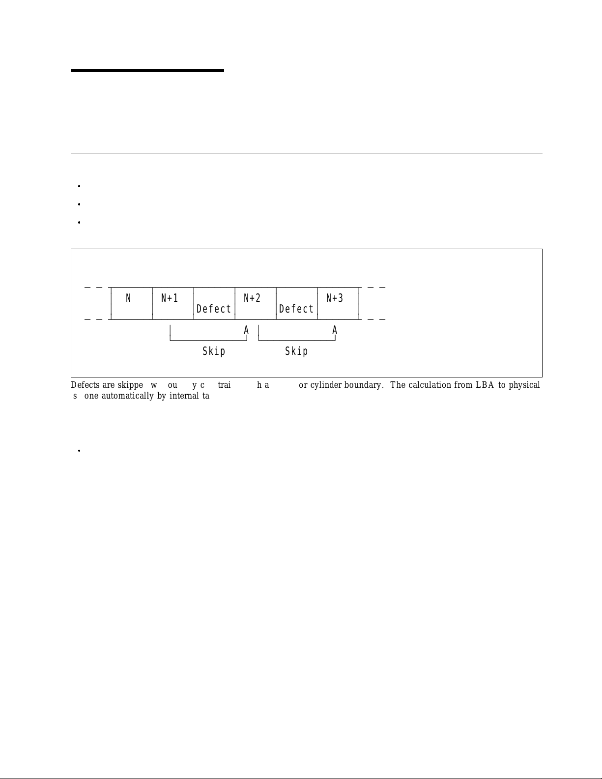
5.0 Physical Format
Media defects ar e remapped t o the next available sector during Form at Process in manufacturing. Th e
mapping from L BA t o the physical locations is calculated b y a n internal maintained table.
5.1 Shipped Format (PList)
Data areas are optimally used.
No extra sector is wasted as a spare throughout user data areas.
All pushes generated by defects ar e absorbed by spare tracks of inner zone.
PList Physical Format
Ä Ä ВДДДДДДВДДДДДДВДДДДДДВДДДДДДВДДДДДДВДДДДДДВ Ä Ä
³
N
³
N+1
³³
³³³
Ä Ä БДДДДДДБДДДДДДБДДДДДДБДДДДДДБДДДДДДБДДДДДДБ Ä Ä
Defect
³
АДДДДДДДДДДДДЩ АДДДДДДДДДДДДЩ
Skip Skip
N+2
³³
³³
A
Defect
³
N+3
³
³³
A
Defects ar e skipped without any constraint, such as track or cylinder boundary. The calculation from L B A to physical
is done automatically by internal table.
5.2 Reassigned Format (G-List)
G-List is prepared for 3327 LBAs.
Re-re-assign of the same L B A does not increase G-List entry.
A cylinder for spare sectors is prepared in every 256 cylinders.
Note: There is possibility to have G-List entry during the drive usage including early period. It is mainly
caused by handling problem, and G-List entry is normal maintenance work of Hard Disk Drive.
Copyright IBM Corp. 1998, 1999 19
Page 30

20 OEM Spec. of DNES-3xxxxx Revision 1.2
Page 31
6.0 Specification
6.1 Electrical Interface Specification
6.1.1 Power Connector
Power pin assignment of 80-pin (SCA-2) model is shown in 6.8.3.3, “80-pin Model” on page 53 and 6.1.2.4,
“SCSI Signal Connector (80-pin SCA-2 LVD/SE Multi-mode)” o n page 25.
Power connector of 50-pin models comply with the ANSI SCSI"A" connector specifications.
Power connector of 68-pin models comply with the ANSI SCSI"P" connector specifications.
Connector of 80-pin models comply with SFF-8046 Revision 2.1.
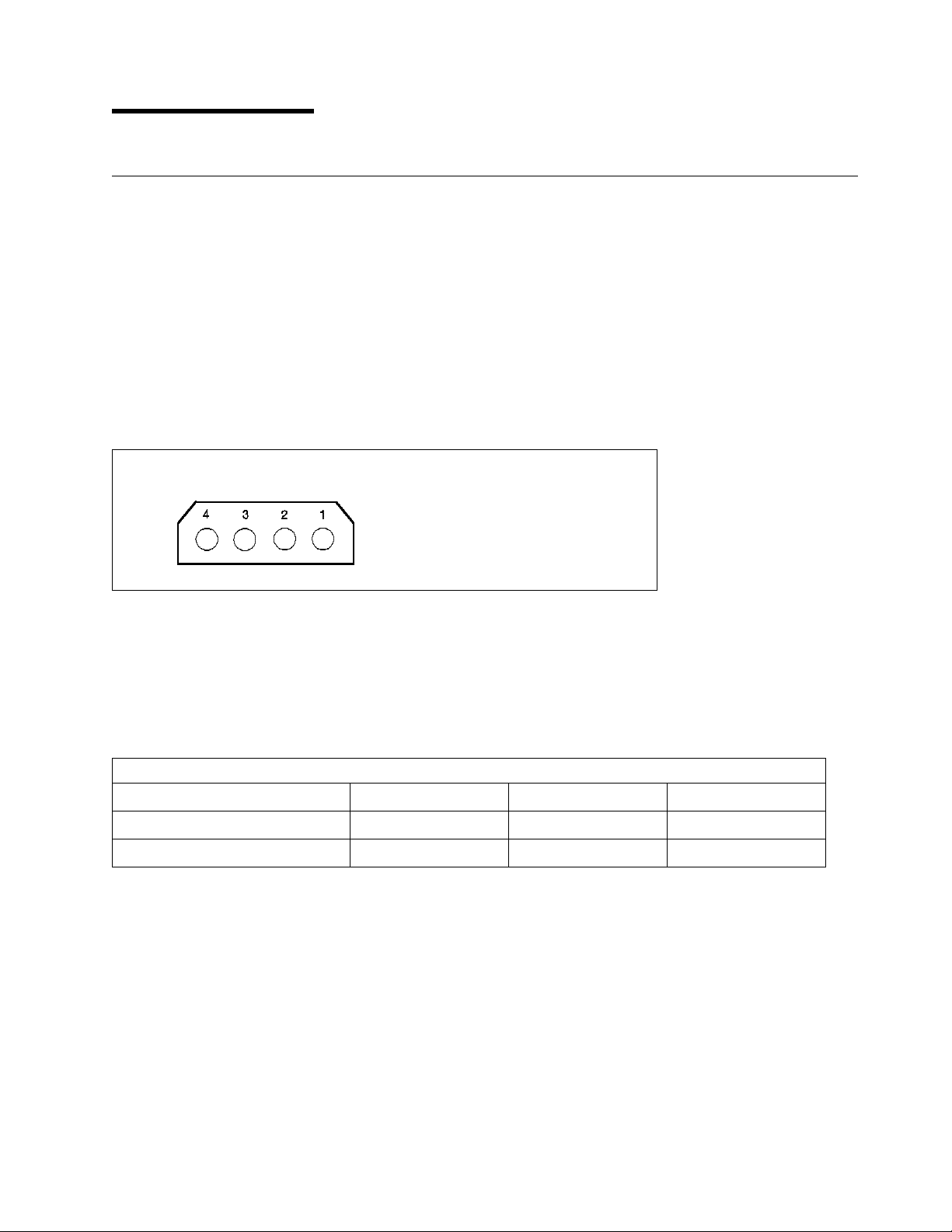
Power pin assignment of 50-pin a nd 68-pin models is as shown below.
Pin
1
2
3
4
Figure 14. Power Connector Pin Assignments
Voltage
+12V
GND
GND
+5V
6.1.2 SCSI Bus Connector
DNES-3xxxxx has 50-pin, 68-pin or 80-pin SCA-2 SCSI connectors as follows.
Figure 15. SCSI Connector vs Models
Model 50-pin 68-pin 80-pin SCA-2
SE model Yes Yes No
LVD/SE Multi-mode model No Yes Yes
Copyright IBM Corp. 1998, 1999 21
Page 32

6.1.2.1 SCSI Signal Connector (50-pin SE)
The SCSI signal connector complies wi th ANSI SCSI-2.
Figure 16. Table of Signals
PIN SIGNAL PIN SIGNAL
01
03
05
07
09
11
13
15
17
19
21
23
25
27
29
31
33
35
37
39
41
43
45
47
49
Ground
Ground
Ground
Ground
Ground
Ground
Ground
Ground
Ground
Ground
Ground
Ground
Open
Ground
Ground
Ground
Ground
Ground
Ground
Ground
Ground
Ground
Ground
Ground
Ground
02
04
06
08
10
12
14
16
18
20
22
24
26
28
30
32
34
36
38
40
42
44
46
48
50
-DB(0)
-DB(1)
-DB(2)
-DB(3)
-DB(4)
-DB(5)
-DB(6)
-DB(7)
-DB(P)
Ground
Ground
Ground
T RM Power
Ground
Ground
-ATN
Ground
-BSY
-ACK
-RST
-MSG
-SEL
-C/D
-REQ
-I/O
22 OEM Spec. of DNES-3xxxxx Revision 1.2
Page 33

6.1.2.2 SCSI Signal Connector (68-pin SE)
Th e pin assignments of interface signals conforms t o ANSI SCSI-3 X3T10/855D as follows.
Figure 17. Table of Signals
Connector
Contact
Number
01
02
03
04
05
06
07
08
09
10
11
12
13
14
15
16
17
18
19
20
21
22
23
24
25
26
27
28
29
30
31
32
33
34
Signal Name Connector
Ground
Ground
Ground
Ground
Ground
Ground
Ground
Ground
Ground
Ground
Ground
Ground
Ground
Ground
Ground
Ground
TERMPWR
TERMPWR
(Open)
Ground
Ground
Ground
Ground
Ground
Ground
Ground
Ground
Ground
Ground
Ground
Ground
Ground
Ground
Ground
Contact
Number
35
36
37
38
39
40
41
42
43
44
45
46
47
48
49
50
51
52
53
54
55
56
57
58
59
60
61
62
63
64
65
66
67
68
Signal Name
-DB(12)
-DB(13)
-DB(14)
-DB(15)
-DB(P1)
-DB(0)
-DB(1)
-DB(2)
-DB(3)
-DB(4)
-DB(5)
-DB(6)
-DB(7)
-DB(P0)
Ground
Ground
TERMPWR
TERMPWR
(Open)
Ground
-ATN
Ground
-BSY
-ACK
-RST
-MSG
-SEL
-C/D
-REQ
-I/O
-DB(8)
-DB(9)
-DB(10)
-DB(11)
Note: 8 bit devices which connect t o t he P-cable should be the following signals inactive (high):
-DB(8),-DB(9),-DB(10),-DB(11),-DB(12),-DB(13),-DB(14),-DB(15),-DB(P1)
All other signals shall be connected as defined.
Specification 23
Page 34

6.1.2.3 SCSI Signal Connector (68-pin LVD/SE Multi-mode)
Th e pin assignments of interface signals conforms t o ANSI SPI-2 T10 Project 1142D Revision 19 as follows.
Figure 18. Table of Signals
Connector
Contact
Number
01
02
03
04
05
06
07
08
09
10
11
12
13
14
15
16
17
18
19
20
21
22
23
24
25
26
27
28
29
30
31
32
33
34
Signal Name Connector
+DB(12)
+DB(13)
+DB(14)
+DB(15)
+DB(P1)
+DB(0)
+DB(1)
+DB(2)
+DB(3)
+DB(4)
+DB(5)
+DB(6)
+DB(7)
+DB(P)
Ground
DIFFSENS
Reserved
Reserved
Reserved
Ground
+ATN
Ground
+BSY
+ACK
+RST
+MSG
+SEL
+C/D
+REQ
+I/O
+DB(8)
+DB(9)
+DB(10)
+DB(11)
Contact
Number
35
36
37
38
39
40
41
42
43
44
45
46
47
48
49
50
51
52
53
54
55
56
57
58
59
60
61
62
63
64
65
66
67
68
Signal Name
-DB(12)
-DB(13)
-DB(14)
-DB(15)
-DB(P1)
-DB(0)
-DB(1)
-DB(2)
-DB(3)
-DB(4)
-DB(5)
-DB(6)
-DB(7)
-DB(P0)
Ground
Ground
Reserved
Reserved
Reserved
Ground
-ATN
Ground
-BSY
-ACK
-RST
-MSG
-SEL
-C/D
-REQ
-I/O
-DB(8)
-DB(9)
-DB(10)
-DB(11)
24 OEM Spec. of DNES-3xxxxx Revision 1.2
Page 35

6.1.2.4 SCSI Signal Connector (80-pin SCA-2 LVD/SE Multi-mode)
The 80-pin SCA-2 model uses an A MP connector which is compatible with SFF-8046 Revision 2.1.
Figure 19. Table of Signals
Connector
Contact
Number
01
02
03
04
05
06
07
08
09
10
11
12
13
14
15
16
17
18
19
20
21
22
23
24
25
26
27
28
29
30
31
32
33
34
35
36
37
38
39
40
Signal Name Connector
12 Volt Charge
12 Volt
12 Volt
12 Volt
Reserved
Reserved
-DB(11)
-DB(10)
-DB(9)
-DB(8)
-I/O
-REQ
-C/D
-SEL
-MSG
-RST
-ACK
-BSY
-ATN
-DB(P0)
-DB(7)
-DB(6)
-DB(5)
-DB(4)
-DB(3)
-DB(2)
-DB(1)
-DB(0)
-DB(P1)
-DB(15)
-DB(14)
-DB(13)
-DB(12)
5 Volt
5 Volt
5 Volt Charge
Reserved
RM T START
SCSI I D (0)
SCSI I D (2)
Contact
Number
41
42
43
44
45
46
47
48
49
50
51
52
53
54
55
56
57
58
59
60
61
62
63
64
65
66
67
68
69
70
71
72
73
74
75
76
77
78
79
80
Signal Name
12V Ground
12V Ground
12V Ground
MATED 1
Reserved
DIFFSENS
+DB(11)
+DB(10)
+DB(9)
+DB(8)
+I/O
+REQ
+C/D
+SEL
+MSG
+RST
+ACK
+BSY
+ATN
+DB(P0)
+DB(7)
+DB(6)
+DB(5)
+DB(4)
+DB(3)
+DB(2)
+DB(1)
+DB(0)
+DB(P1)
+DB(15)
+DB(14)
+DB(13)
+DB(12)
MATED 2
5V Ground
5V Ground
ACTIVE L ED O UT
DELAYED START
SCSI I D (1)
SCSI I D (3)
Note: Pin #38,39,40,77,78,79,80 work as Logical OR w i th jumper pins on Option Jumper Block.
Specification 25
Page 36

6.1.3 SCSI Cable
6.1.3.1 SE mode
The maximum cumulative cable length whe n using single-ended transceiver shou l d b e 3 meters. Implementations that limit th e transfer rate to a maximum of 5 Mbyte transfers per second may extend the cumulative
cable length t o 6 meters. (ANSI SCSI-3 X3T10/855D Revision 15a).
The maximum cumulative signal path between terminators shall be 3.0 meters w he n using u p to 4 maximum
capacitance (25pF) devices. The maximum cumulative signal pa th length between terminators shall be 1.5
meters w h en using from five to eight maximum capacitance devices. (ANSI SCSI-3 FAST-20
X3T10/1071D).
6.1.3.2 LVD mode
The maximum cumulative cable length whe n using L VD transcever must be 12 meter. For t he details of
specification, refer to ANSI SCSI Parallel Interface-2 (SPI-2) T 10 Project 1142D Revision 19.
6.1.4 SCSI Bus Terminator
6.1.4.1 SE model
Single-ended 50/68-pin models have SCSI active terminator. I t can be enabled by installing a jumper plug at
position #6 of J-4 jumper block, or connecting pins # 9 a nd # 10 of t he auxiliary connector on 68-pin model.
System is responsible for making sure that all required signals are terminated at b o t h ends of t he bus cable.
6.1.4.2 LVD/SE Multi-mode model
Both 68-pin an d 80-pin of LVD/SE Multi-mode models do not have any SCSI Terminator.
It is user responsibility to mak e sure that all required signals are adequately terminated at bo t h ends of the
bus cable.
6.1.4.3 Terminator Power
The 50-pin a nd 68-pin models supply terminator power to pin #26 of 50-pin connector and pin #17,18,51,52
of 68-pin connector through current limiter an d s ho tk y diode w he n jumper plug is set at position # G of J-6
jumper block. F or jumper setting, see 6.2, “Option Jumper Block” on page 28.
The 80-pin models do not supply terminator power.
6.1.5 Hot Plug / Unplug
The 80-pin (SCA-2) model supports Ho t Plug/Unplug.
The 50-pin model and 68-pin model do n ot support H ot Plug/Unplug.
6.1.6 SCSI Bus Electrical Characteristics
SCSI Bus Electrical Characteristics of &modelx. comply with ANSI SPI-2 T10 Project 1142D Revision 19.
26 OEM Spec. of DNES-3xxxxx Revision 1.2
Page 37

6.1.7 Auxiliary Connector on 68-pin Model
The 68-pin models contain Auxiliary Connector between power connector and 68-pin SCSI connector in
addition t o Option Jumper Block. The setting at Option Jumper Block an d t he Auxiliary Connector work
as logical OR. The drive conforms SFF-8009 Rev3.0.
Pin #1,3,5,7 specify SCSI-ID as -DAS0,1,2,3. Tie-down to the ground is to assert.
Pi n #2,4,6,12 are reserved, an d should be open.
Pin #8 is for external L ED cathod.
If pin # 9 is tied-down t o the ground on SE model, SCSI Terminator is enabled.
Enable SCSI Terminator
(Varid only on SE model)
+5V
ДДДДДДДДДДДДДДДДДДДДД¿³³³³ÚÄÄÄ Ä
ДДДДДД¿ ЪДДДДДДДДДДДДДДД Ä
³ ³ ЪДДДДДДДДДДД Ä
³ ³ ³ ЪДДДДДДД Ä
³³³³³³
Pin#: 1197531
ЪДДДДДДДДДДД¿ ЪДДДДДДДДДДД¿
³ ЪДДДДДДДДДЩ АДДДДДДДДД¿ ³
³³ ³³
³³
³³ ³³
³³
³³ ³³
³ ÀÄ¿ ЪДДДДД¿ ÚÄÙ ³
АДДДЩ АДДДДДЩ АДДДЩ
oooooo
oooooo
12108642
³³³³³³
(Reserved)
GROUND
LED Cathod
ДДДДДДДДДДДДДДÙ³³³³ÀÄÄÄ
ДДДДДДДДДДДДДДДДДДДДДДÙ ³ ³ АДДДДДДД
ДДДДДДДДДДДДДДДДДДДДДДЩ АДДДДДДДДДДД
Note: Pin #9 is valid only for SE model.
LVD/SE Multi
Ä
mode model has no terminator.
DAS3
DAS2
DAS1
DAS0
³³
³³
ÄÄ¿
ÃÄÄÄ
³
ÄÄÙ
(Reserved)
(Reserved)
(Reserved)
SCSI ID
Auxiliary Connector
Specification
27
Page 38

6.2 Option Jumper Block
Two jumper blocks, J-4 and J-6, are located on the card of 50/68-pin models as shown below.
One jumper block, J-4, is located on t he card of 80-pin models as shown below.
J-4 has 12 positions (#1 - #12).
Some of jumper pins on J-4 c an be controlled also through Auxiliary Connector on 68-pin models as
descrived i n 6.1.7, “Auxiliary Connector on 68-pin Model” on page 27. These controls work as logical OR
between Option Jumper Block an d Auxiliary Connector.
Some of jumper pins on J-4 c an be controlled also through 80-pin SCA-2 connector as described in 6.1.2.4,
“SCSI Signal Connector (80-pin SCA-2 LVD/SE Multi-mode)” o n page 25. These controls work as logical
O R between Option Jumper Block a nd SCA-2 connector.
J-6 has 7 positions ( # A - # G ) and controls Terminator Power supply.
28 OEM Spec. of DNES-3xxxxx Revision 1.2
Page 39

ЪДДДДВДДДДДДДДДДДДДДВДДДДДДДДДДДДДДДДДДДД¿
³ ³ ÚÄÄÄ´
³³ ³JÄ6³<ÄÄ
³
C
³³³
³
o
³ ÀÄÄÄ´
³
n
³³ ³
³
n
³
Logic card
³
e
³³ ³
³
c
³ ÚÄÄÄ´
³
t
³³³ ³
³
o
³³
³
r
³³³
³³ ³³ ³
³ ³ ÀÄÄÄ´
АДДДДБДДДДДДДДДДДДДДБДДДДДДДДДДДДДДДДДДДДЩ
Position #A
Option Jumper
Block JÄ6
Position #G
³³
Position #1
JÄ4³<ÄÄOption Jumper
Block JÄ4
Position #12
³
³
³
³
³
³
³
³
Note: 80Äpin models do not have Option Jumper Block JÄ6.
Ä
Jumper Block J
6
(50/68Äpin models only)
ЪДДДДДДДДДДДДДДДДДДДДДДДДДДДДДДДДД¿ ³³
ДДДДДДДДДДДДДБД¿
Logic Card³GFEDCBA
ДДДДДДДДДДДДДДД´
ДДДДДДДДДДДДДДДДДДДДДДДДДДДДДДДДДДДДДДДДДДДДДДДДДДДЩ³
ooooooo
ooooooo
АДДДДДДДДДДДДДДДДДДДДДДДДДДДДДЩ ³³
ÚÄÁÄ¿ ³³
³³³³
ГДДДЩ ³³
Disk Enclosure
ДДДДДДДДДДДДДДДДДДДДДДДДДДДДДДДДДДДДДДДДДДДДДДДДДДДДЩ
Ú¿
³³
³³
³
³
³
Ú¿
³³ ЪДДДДДДДДДДДДДДДДДДДДДДДДДДДДДДДДДДДДДДДДДДДДДДДДДДДДД¿
³³ ÚÄÁÄ¿
³³ ³ ³
³³ ÀÄÄÄ´
³³ АДДДДДДДДДДДДДДДДДДДДДДДДДДДДДДДДДДДДДДДДДДДДДДДДДЩ
³³
³АДДДДДДДДДДДДДДДДДДДДДДДДДДДДДДДДДДДДДДДДДДДДДДДДДДДДДДДДДДДДДДДДДДДДД
³
³
³
АДДДДДДДДДДДДДДДДДДДДДДДДДДДДДДДДДДДДДДДДДДДДДДДДДДДДДДДДДДДДДДДДДДДДДД
Figure 20. Jumper Pins
oooooooooooo
121110987654321
oooooooooooo
Jumpser Block JÄ4
Disk Enclosure
ЪДБДДДДДДДДДДД
³
Logic Card
ГДДДДДДДДДДДДД
Specification
29
Page 40

6.2.1 Jumper Pin of 50-pin SE model
50Äpin SE model
ЪДДДДДДД¿
³JÄ6³
³ АДДДДДД¿
³³
GROUND
ДДДДВДДД ³
Open
SCSI Bus
oAo
³³ ³
ÃÄÄÄ ³
³³ ³
ÃÄÄÄ ³
³³ ³
ÃÄÄÄ ³
³³ ³
ÀÄÄÄ ³
ÄÄÄ ³
ÄÄÄ ³
oBo
oCo
oDo
oEo
³³
oFo
³³
o(G)o
³³
³ ЪДДДДДДЩ
³³
АДДДДДДДЩ
³ ÄÄÄ
³ ÄÄÄ
³ ÄÄÄ
³ ÄÄÄ
³ ÄÄÄ
³ ÄÄÄ
³ ÄÄÄ
( x) indicates Ship Default
Reserved
Reserved
Reserved
Reserved
Reserved
Open
Enable Terminator Power Supply
GROUND
ДДДДВДДД ³
LED Anode
ЪДДДДДДД¿
³JÄ4³
³ АДДДДДД¿
³³
o1o
³³ ³
ÃÄÄÄ ³
³ ³ ³ ÃÄÄ
ÃÄÄÄ ³
³³³³
ÃÄÄÄ ³
³³ ³
ÃÄÄÄ ³
³³ ³
ÃÄÄÄ ³
³³ ³
ÃÄÄÄ ³
³³ ³
ÃÄÄÄ ³
³³ ³
ÃÄÄÄ ³
³³ ³
ÃÄÄÄ ³
³³ ³
ÀÄÄÄ ³
ÄÄÄ ³
o(2)o
o(3)o
o4o
o(5)o
o(6)o
o7o
o8o
o9o
o10o
o11o
³³
o12o
³³
³ ЪДДДДДДЩ
³³
АДДДДДДДЩ
³ ÄÄÄ
³ ÄÄÄ Ä
³ ÄÄÄ Ä
³ ÄÄÄ Ä
³ ÄÄÄ
³ ÄÄÄ
³ ÄÄÄ
³ ÄÄÄ
³ ÄÄÄ
³ ÄÄÄ
³ ÄÄÄ
³ ÄÄÄ
Reserved
DAS2
ÄÄ¿
SCSI ID
DAS1
DAS0
ÄÄ´
ÄÄÙ
Enable Auto Spin Up
Enable SCSI Terminator
Disable Unit Attention
Enable TIÄSDTR
Enable Auto Start Delay
Delay Start 6/12
Disable SCSI Parity Check
LED Cathod
Figure 21. Jumper Pin of 50-pin SE model
30 OEM Spec. of DNES-3xxxxx Revision 1.2
Page 41

6.2.2 Jumper Pin of 68-pin SE model
68Äpin SE model
ЪДДДДДДД¿
³JÄ6³
³ АДДДДДД¿
³³
GROUND
ДДДДВДДД ³
Open
SCSI Bus
oAo
³³ ³
ÃÄÄÄ ³
³³ ³
ÃÄÄÄ ³
³³ ³
ÃÄÄÄ ³
³³ ³
ÀÄÄÄ ³
ÄÄÄ ³
ÄÄÄ ³
oBo
oCo
oDo
oEo
³³
oFo
³³
o(G)o
³³
³ ЪДДДДДДЩ
³³
АДДДДДДДЩ
³ ÄÄÄ
³ ÄÄÄ
³ ÄÄÄ
³ ÄÄÄ
³ ÄÄÄ
³ ÄÄÄ
³ ÄÄÄ
( x) indicates Ship Default
Reserved
Reserved
Reserved
Reserved
Reserved
Open
Enable Terminator Power Supply
GROUND
ДДДДВДДД ³
LED Anode
ЪДДДДДДД¿
³JÄ4³
³ АДДДДДД¿
³³
o1o
³³³³
ÃÄÄÄ ³
³ ³ ³ ÃÄÄ
ÃÄÄÄ ³
³³³³
ÃÄÄÄ ³
³³ ³
ÃÄÄÄ ³
³³ ³
ÃÄÄÄ ³
³³ ³
ÃÄÄÄ ³
³³ ³
ÃÄÄÄ ³
³³ ³
ÃÄÄÄ ³
³³ ³
ÃÄÄÄ ³
³³ ³
ÀÄÄÄ ³
ÄÄÄ ³
o(2)o
o(3)o
o4o
o(5)o
o(6)o
o7o
o8o
o9o
o10o
o11o
³³
o12o
³³
³ ЪДДДДДДЩ
³³
АДДДДДДДЩ
³ ÄÄÄ Ä
³ ÄÄÄ Ä
³ ÄÄÄ Ä
³ ÄÄÄ Ä
³ ÄÄÄ
³ ÄÄÄ
³ ÄÄÄ
³ ÄÄÄ
³ ÄÄÄ
³ ÄÄÄ
³ ÄÄÄ
³ ÄÄÄ
DAS3
DAS2
ÄÄ¿
ÄÄ´
SCSI ID
DAS1
DAS0
ÄÄ´
ÄÄÙ
Enable Auto Spin Up
Enable SCSI Terminator
Disable Unit Attention
Enable TIÄSDTR/WDTR
Enable Auto Start Delay
Delay Start 6/12
Disable SCSI Parity Check
LED Cathod
Figure 22. Jumper Pin of 68-pin SE model
Specification 31
Page 42

6.2.3 Jumper Pin of 68-pin LVD/SE Multi-mode model
68Äpin LVD/SE MultiÄmode model
ЪДДДДДДД¿
³JÄ6³
³ АДДДДДД¿
³³
GROUND
|
ДДДДВДДД ³
Open
SCSI Bus
oAo
³³ ³
ÃÄÄÄ ³
³³ ³
ÃÄÄÄ ³
³³ ³
ÃÄÄÄ ³
³³ ³
ÀÄÄÄ ³
ÄÄÄ ³
ÄÄÄ ³
oBo
oCo
oDo
oEo
³³
oFo
³³
oGo
³³
³ ЪДДДДДДЩ
³³
АДДДДДДДЩ
³ ÄÄÄ
³ ÄÄÄ
³ ÄÄÄ
³ ÄÄÄ
³ ÄÄÄ
³ ÄÄÄ
³ ÄÄÄ
Reserved
Reserved
Reserved
Reserved
Reserved
Open
Enable Terminator Power Supply
( x) indicates Ship Default
GROUND
ДДДДВДДД ³
LED Anode
ЪДДДДДДД¿
³JÄ4³
³ АДДДДДД¿
³³
o1o
³³³³
ÃÄÄÄ ³
³ ³ ³ ÃÄÄ
ÃÄÄÄ ³
³³³³
ÃÄÄÄ ³
³³ ³
ÃÄÄÄ ³
³³ ³
ÃÄÄÄ ³
³³ ³
ÃÄÄÄ ³
³³ ³
ÃÄÄÄ ³
³³ ³
ÃÄÄÄ ³
³³ ³
ÃÄÄÄ ³
³³ ³
ÀÄÄÄ ³
ÄÄÄ ³
o(2)o
o(3)o
o4o
o(5)o
o6o
o7o
o8o
o9o
o10o
o11o
³³
o12o
³³
³ ЪДДДДДДЩ
³³
АДДДДДДДЩ
³ ÄÄÄ Ä
³ ÄÄÄ Ä
³ ÄÄÄ Ä
³ ÄÄÄ Ä
³ ÄÄÄ
³ ÄÄÄ
³ ÄÄÄ
³ ÄÄÄ
³ ÄÄÄ
³ ÄÄÄ
³ ÄÄÄ
³ ÄÄÄ
DAS3
DAS2
ÄÄ¿
ÄÄ´
SCSI ID
DAS1
DAS0
ÄÄ´
ÄÄÙ
Enable Auto Spin Up
Force SE Mode
Disable Unit Attention
Enable TIÄSDTR/WDTR
Enable Auto Start Delay
Delay Start 6/12
Disable SCSI Parity Check
LED Cathod
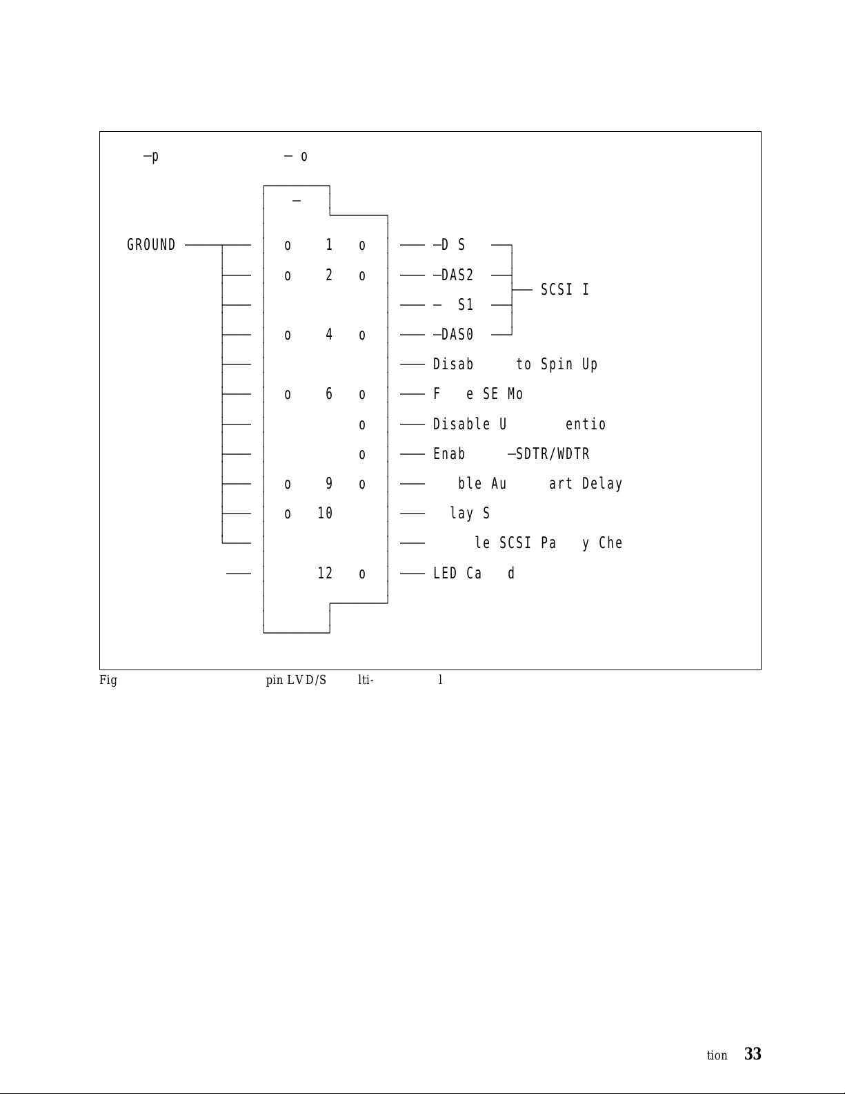
Figure 23. Jumper Pin of 68-pin LVD/SE Multi-mode model
32 OEM Spec. of DNES-3xxxxx Revision 1.2
Page 43
6.2.4 Jumper Pin of 80-pin LVD/SE Multi-mode model
80Äpin LVD/SE MultiÄmode model
( x) indicates Ship Default
ЪДДДДДДД¿
³JÄ4³
³ АДДДДДД¿
³³
GROUND
ДДДДВДДД ³
³³³³
ÃÄÄÄ ³
³ ³ ³ ÃÄÄ
ÃÄÄÄ ³
³³³³
ÃÄÄÄ ³
³³ ³
ÃÄÄÄ ³
³³ ³
ÃÄÄÄ ³
³³ ³
ÃÄÄÄ ³
³³ ³
ÃÄÄÄ ³
³³ ³
ÃÄÄÄ ³
³³ ³
ÃÄÄÄ ³
³³ ³
ÀÄÄÄ ³
LED Anode
o1o
o2o
o3o
o4o
o5o
o6o
o7o
o8o
o9o
o10o
o11o
³³
ÄÄÄ ³
o12o
³³
³ ЪДДДДДДЩ
³³
АДДДДДДДЩ
³ ÄÄÄ Ä
³ ÄÄÄ Ä
³ ÄÄÄ Ä
³ ÄÄÄ Ä
³ ÄÄÄ
³ ÄÄÄ
³ ÄÄÄ
³ ÄÄÄ
³ ÄÄÄ
³ ÄÄÄ
³ ÄÄÄ
³ ÄÄÄ
DAS3
DAS2
ÄÄ¿
ÄÄ´
SCSI ID
DAS1
DAS0
ÄÄ´
ÄÄÙ
Disable Auto Spin Up
Force SE Mode
Disable Unit Attention
Enable TIÄSDTR/WDTR
Enable Auto Start Delay
Delay Start 6/12
Disable SCSI Parity Check
LED Cathod
Figure 24. Jumper Pin of 80-pin LVD/SE Multi-mode model
Specification 33
Page 44

6.2.5 Jumper Signal Description on J-6
6.2.5.1 Position #A - # E on J-6
Reserved.
Jumper setting is n ot allowed.
6.2.5.2 Position # F on J-6
Open.
The pins atre open.
6.2.5.3 Position # G on J-6
Enable Terminator Power Supply.
6.2.6 Jumper Signal Description on J-4
6.2.6.1 Position #1 - #4 on J-4
These four lines (-DAS0, -DAS1, -DAS2, -DAS3) define DNES-3xxxxx device ID o n the SCSI BUS.
-DAS0 is the least significant bi t and -DAS3 is the most significant bit . Device ID is defined as follows.
In case of 50-pin model, Position #1 is Reserved, a nd -DAS3 is not used.
Throughout this paragraph 'on' means a shunt jumper is installed and 'off' means that no shunt jumper is
installed.
Ä
DAS3ÄDAS2ÄDAS1ÄDAS0
Position #
ДДДДДДДДДДДДДДДДДДДДДДДДДДДДДДДДДДДДДДДДДДДДДДДДДДДДДДДДДДД
ÄÄ
> (1) (2) (3) (4) Device ID
off off off off 0 <
ÄÄÄ
Shipping
off off off on 1 default
off off on off 2 of
off off on on 3 80
Ä
pin
off on off off 4
off on off on 5
off on on off 6 <
ÄÄÄ
Shipping
off on on on 7 default
on off off off 8 of
on off off on 9 50/68
Ä
pin
on off on off 10
on off on on 11
on on off off 12
on on off on 13
on on on off 14
on on on on 15
Note: 50
Ä
pin model does not useÄDAS3, and only Device ID's 0 through 7
can be assigned.
Figure 25. SCSI Device ID
34 OEM Spec. of DNES-3xxxxx Revision 1.2
Page 45

6.2.6.2 Position #5 on J-6
50/68-pin model
Enable Auto Spin Up
If a shunt jumper is installed, the drive will spin up automatically after power on reset. If shunt
jumper is not installed, th e drive will not spin up unless a START UNIT command is received.
80-pin model
− Disable Auto Spin Up
If a shunt jumper is not installed, th e drive will spin up automatically after power on reset. If shunt
jumper is installed, t he drive will not spin up unless a START UNIT command is received.
Note: Th e drive ma y not spin u p while SCSI Bus is disconnected an d internal terminator is disabled.
6.2.6.3 Position #6 on J-4
SE model
− Enable SCSI Terminator
If a shunt jumper is installed, t h e internal SCSI active terminator on the drive works.
LVD/SE Multi-mode model
− Force SE mode
If a shunt jumper is installed, the drive is forced to work as Single-End mode drive.
6.2.6.4 Position #7 on J-4
Disable Unit Attention
Installing a shunt jumper enables control of UAI (Unit Attention Inhibit) bit in Mode Page 0.
6.2.6.5 Position #8 on J-4
50-pin model
− Enable TI-SDTR
Installing a shunt jumper enables Target Initiated Synchronous Data Transfer Request Negotiation.
68/80-pin model
− Enable TI-SDTR/WDTR
Installing a shunt jumper enables the following.
— Target Initiated Wide Data Transfer Request Negotiation
— Target Initiated Synchronous Data Transfer Request Negotiation
Specification 35
Page 46

6.2.6.6 Position #9 - #1 0
Auto Start Delay & Delay Start 6/ 1 2
These pins control when and how the drive spins u p with the combination of Position #5 o n J-4.
When bot h Auto Spin up and Auto Start Delayis are enabled, t h e drive start will be delayed by a period of
time multiplied by its ow n SCSI address. If Auto Spin up is disabled, these jumpers will be ignored.
Throughout this paragraph 'on' means a shunt jumper is installed and 'off' means that no shunt jumper is
installed.
Enable/Disable Auto Delay
Auto Start Start
Spin up Delay 6/12
ДДДДДДДДДДДДДДДДДДДДДДДДДДДДДДДДДДДДДДДДДДДДДДДДДДДДДДДДДДДДДДДДДДДДДДДДД
Position #Ä> (5) (9) (10) Option
ДДДДДДДДДДДДДДДДДДДДДДДДДДДДДДДДДДДДДДДДДДДДДДДДДДДДДДДДДДДДДДДДДДДДДДДДД
off (50/68Äpin) any any Drive will Not spin up
on (80
on (50/68
off (80
on (50/68
off (80
Ä
pin) Requires Start Unit command
Ä
pin) off off Spin up immediately after POR
Ä
pin)
Ä
pin) on off Spin up 6 seconds multiplied
Ä
pin) by SCSI address after POR
on (50/68
off (80
Figure 26. Spin Up Control by Jumper
Ä
Ä
pin) by SCSI address after POR
pin) on on Spin up 12 seconds multiplied
36 OEM Spec. of DNES-3xxxxx Revision 1.2
Page 47

6.2.6.7 Position #1 1 on J-4
Disable SCSI Parity Check
Installing a shunt jumpe disables SCSI Parity checking.
6.2.6.8 Position #1 2
LED pins
The L ED pins are used to drive an external Light Emitting Diode. U p to 30 mA of sink current capability
is provided. Th e L ED Anode must be tied to t h e current limited + 5 V source provided o n the pi n for L ED
Anode at the Location #12 on J-4 jumper block. T h e LED Cathode is then connected t o the pin for LE D
Cathod at the Location #12 on J-4 jumper block to complete the circuit.
Refer t o 6.3, “ LED Circuit” on page 39 for more details.
+5V
o
³
>
< 150 Ohm
> Position #12 on
³
³
АДДДДДДДДДДДДДДДДДДДДДДД
JÄ4 Jumper Block
o to LED Anode
³
ÄÄÄ´
³
Figure 27. LE D Circuit
ЪДДДДДДДДДДДДДДДДДДДДДДД
/
\
АДДДД¿
³
ДДБДД
///
o to LED Cathod
Specification
37
Page 48

6.2.7 Shipping Default
Default jumer setting depends o n model.
50-pin SE model
Refer t o 6.2.1, “Jumper Pin of 50-pin S E model” o n page 30.
68-pin SE model
Refer t o 6.2.2, “Jumper Pin of 68-pin S E model” o n page 31.
68-pin LVD/SE Multi-mode model
Refer t o 6.2.3, “Jumper Pin of 68-pin LVD/SE Multi-mode model” on page 32.
80-pin LVD/SE Multi-mode model
No jumper is set as shipping default.
Refer t o 6.2.4, “Jumper Pin of 80-pin LVD/SE Multi-mode model” on page 33.
38 OEM Spec. of DNES-3xxxxx Revision 1.2
Page 49

6.3 LED Circuit
Position #12 on Jumper Block J-4 is used t o drive an external LED.
Instead of the the jumper pins, the following pins can be used to drive LED.
68-Pin model : Auxiliary Connector Pin #8 and #11.
Refer t o 6.1.7, “Auxiliary Connector on 68-pin Model” on page 27 and 6.3.2, “68-Pin Model” o n
page 40.
80-Pin model : SCA-2 Connector Pin #77 as shown in 6.8.3.3, “80-pin Model” on page 53 an d 6.3.3,
“80-Pin Model” o n page 41.
Th e schematics of LED circuit on each model are as follows.
6.3.1 50-Pin Model
DNESÄ318350 / DNESÄ309170 50ÄPin Model
+5V
o
³
³
>
< 150 Ohm
>
³
³
³
АДДДДДДДДДДДДДДДДДДДД
Position #12 on
Jumper Block JÄ4
o to LED Anode
ЪДДДДДДДДДДДДДДДДДДДД
³
/
ÄÄÄ´
³
\
АДДДД¿
³
³
ДДБДД
///
Figure 28. LE D Circuit of 50-Pin Model
o to LED Cathod
Specification
39
Page 50

6.3.2 68-Pin Model
DNESÄ318350 / DNESÄ309170 68ÄPin Model : : Example of Us age
5V : :
o::
³
³
ГДДДДДДДДДДДДДДДДДДДДДДДДДДДДДДДДДДД
³
³
>::
< 150 Ohm : :
>::\/
³
³
³
АДДДДДДДДДДДДДДДДДДДДДДДДДДДДДДДДДДД
ЪДДДДДДДДДДДДДДДДВДДДДДДДДДДДДДДДДДДДДДДД
³
/
ÄÄÄ´ ³
³
\
АДДДД¿ ³
³
³
³
³³
³³
ДДБДД ³
///
: : at System Side
::
::
Auxiliary : :
Connector Pin #11 :
oo
for LED Anode : :
::
ДДДДДДДДД¿
³
³
³
ДДДБДДД
: : \ / LED
::
to LED Anode :
o:
Position #12 on : :
Jumper Block JÄ4: :
o:
³
to LED Cathod
:
³
::
::
>::
< 150 Ohm : :
>::
::
Auxiliary : :
Connector Pin #8 :
АДДДДДДДДДДДДДДДДДДДДДДД
oo
ДДДДДДДДДЩ
ÄÂÄ
³
³
³
³
³
³
³
³
³
³
³
³
³
³
³
for LED Cathod : :
::
::
Figure 29. LE D Circuit of 68-Pin Model
40 OEM Spec. of DNES-3xxxxx Revision 1.2
Page 51

6.3.3 80-Pin Model
DNESÄ318350 / DNESÄ309170 80ÄPin (SCAÄ2) Model : : Example of Usage
ЪДДДДДДДДДДДДДДДДВДДДДДДДДДДДДДДДДДДДДДДД
³
/
ÄÄÄ´ ³
³
\
АДДДД¿ ³
³
³
³
³³
³³
ДДБДД ³
///
: : at System Side
::
::
+5V : : +5V
o::o
³
³
>::
< 150 Ohm : :
>::
³
³
³
³
³
³
³
АДДДДДДДДДДДДДДДДДДДДДДД
to LED Anode :
Position #12 on : :
Jumper Block JÄ4: :
³
³
to LED Cathod
>::
< 150 Ohm : :
>::
SCAÄ2 Connector Pin #77 :
АДДДДДДДДДДДДДДДДДДДДДДД
::
::
::
::
::
³
³
³
³
³
³
³
ДДДБДДД
:: \/
: : \ / LED
::
o:
o:
:
::
::
::
::
oo
ДДДДДДДДДЩ
ÄÂÄ
³
³
³
³
³
³
³
³
³
³
³
³
³
³
³
for LED Cathod : :
::
::
Figure 30. LE D Circuit of 80-Pin (SCA-2) Model
Specification 41
Page 52

6.4 Environment
Figure 31. Environmental Condition
Operating Conditions
Temperature 5 to 55 ˚C (See note)
Relative Humidity 8 to 90 %RH
Maximum Wet Bulb Temperature 29.4 ˚C
Maximum Temperature Gradient 15 ˚ C / Hour
Altitude −300 to 3048 m
Non-Operating Conditions
Temperature − 40 to 65 ˚C
Relative Humidity 5 to 95 %RH
Maximum Wet Bulb Temperature 35 ˚C
Maximum Temperature Gradient 15 ˚ C / Hour
Altitude −300 to 12,000 m
Note:
The system ha s to provide sufficient ventilation to maintai n a surface temperature below 60[ ˚C ] at the
center of drive top cover.
Non-condensing should be kept at any time.
Maximum storage period with shipping package is one year.
Figure 32. Limits of Temperature an d Humidity
42 OEM Spec. of DNES-3xxxxx Revision 1.2
Page 53

6.5 Cooling Requirements
The system ha s t o provide sufficient ventilation to m ain ta in a surface temperature below 60˚ C at the center
of t h e top cover of the drive.
The system ha s t o provide sufficient ventilation to keep t he limits of component temperature as shown
below.
Figure 33. Maximum Allowable Module Surface Temperature
Module Name Location Maximum Allowable Surface Temperature
MPU + HDC 1 90˚C
DRAM 2 90˚C
SCSI Terminator 3 90˚C
VCM + Spindle Driver 4 95˚C
Cannel 5 95˚C
Figure 34. Module Location
Specification
43
Page 54

6.6 DC Power Requirements
Connection t o the product should be made in isolated secondary circuits (SELV). T he following voltage
specification is applied a t t h e power connector of the drive.
N o special power on/off sequencing is required.
Figure 35. Input Voltage
During run and spin up Absolute max spike voltage Supply rise time
+ 5 Volts Supply 5V +/- 5% 7V 0 - 200 ms
+12 Volts Supply 12V + /- 5 % (*1) 15V 0 - 400 ms
Figure 36. Power Supply Current of DNES-318350 with SCSI Terminator Enabled
+5Volts +12Volts Total
(All values in Amps.)
Idle Average 0.37 0.02 0.42 0.03 6.9
Idle ripple (peak-to-peak) 0.24 0.02 0.55 0.10
Seek average (*2) 0.48 0.02 0.93 0.03 13.6
Start u p (max) 0.75 0.03 2.00 0.13
Pop Mean Std.Dev Pop Mean Std.Dev
(W)
Random R /W peak (*3) 0.81 0.10 1.85 0.10
Random R /W average (*3) 0.54 0.02 0.63 0.03 10.3
Figure 37. Power Supply Current of DNES-309170 with SCSI Terminator Enabled
+5Volts +12Volts Total
(All values in Amps.)
Idle Average 0.36 0.02 0.29 0.03 5.3
Idle ripple (peak-to-peak) 0.24 0.02 0.55 0.10
Seek average (*2) 0.47 0.02 0.87 0.03 12.8
Start u p (max) 0.75 0.03 2.00 0.13
Random R /W peak (*3) 0.73 0.10 1.85 0.10
Random R /W average (*3) 0.53 0.02 0.56 0.03 9.4
Notes:
1. 12V + /- 7% is acceptable during spin u p , b u t the spin up time is not guaranteed.
2. Random Seeks at 100% duty cycle.
3. Seek Duty = 40%, W/ R Duty = 60%, Idle Duty = 0 %.
Pop Mean Std.Dev Pop Mean Std.Dev
(W)
44 OEM Spec. of DNES-3xxxxx Revision 1.2
Page 55

Figure 38. Power Supply Generated Ripple at Drive Power Connector
Maximum Notes
+5V DC 250 [mV pp] 0-10 [MHz]
+12V DC 250 [m V pp] 0-10 [MHz]
During drive start u p and seeking, 12 volt ripple is generated by th e drive (referred t o as dynamic loading). If
several files have their power daisy chained together the n the power supply ripple plus other drive's dynamic
loading must remain within the regulation tolerance of ± 0.5%. A common supply with separate power
leads to each drive is a more desirable method of power distribution.
To prevent external electrical noise from interfering with t h e drive's performance, the drive must be held by
four screws in a user system frame which has no electrical level difference at the four screws position, and has
less than ± 300 milivolts peak to peak level difference to the drive power connector ground.
Specification 45
Page 56

6.6.1 Start Up Current
Figure 39. Typical Current Wave Form of 12V at Start Up of DNES-309170
Figure 40. Typical Current Wave Form of 12V at Start Up of DNES-318350
46 OEM Spec. of DNES-3xxxxx Revision 1.2
Page 57

6.7 Reliability
6.7.1 Contact Start Stop (CSS)
The drive is designed to withstand a minimum of 40,000 contact start/stop cycles at 40˚C with 13-25% relative humidity.
The drive is designed to withstand a minimum of 10,000 contact start/stop cycles at operating environment
conditions specified in 6.4, “Environment” on page 42.
6.7.2 Data Reliability
Probability of not recovering d a t a ....... 1 in 1013bits read
ECC On-The-Fly correction, performed as a part of read channel function, recovers up to 12 symbols of
error in 1 sector. (1 symbol is 8 bits.)
6.7.3 Seek/ID Mis-compare Errors
A non-recoverable seek/ID mis-compare error is defined as a seek operation that cannot be corrected b y
fixed disk error recovery procedure. Seek errors occurring for field format operations are considered t o be
non-recoverable.
N o drive h a s more th an one non-recoverable seek/ID mis-compare error per 5 milion seek operations (1 in 5
x106) when operated at the full range of voltage an d environmental conditions.
Non-recoverable seek/ID mis-compare errors indicate a defective drive.
6.7.4 Equipment Errors
A recoverable equipment error is any error other than a seek/ID mis-compare error or read error that is
detected a n d corrected by th e drive error recovery procedure. Examples are Write Fault, Drive No t Ready
and internal drive errors.
N o drive h a s more th an one recoverable equipment error per 108reads, 106writes or 106seeks operations
when operated at the full range of voltage a n d environmental conditions.
Non-recoverable equipment errors indicate a defective drive.
6.7.5 Failure Prediction ( PFA / S.M.A.R.T.)
DNES-3xxxxx supports Informational Exceptions Control Page (1C) defined in SCSI-3. T he function
enables t he drive to report sense codes of FAILURE PREDICTION THRESHOLD EXCEEDED to the
host system.
Th e page 1 C specifies enable/disable, reporting method, and report count.
In case the drive exceeded the failure prediction threshold, the drive returns Check Condition on any
command. Then, per specified reporting method in Mode Page 1C, 0/5D/00, 1/5D/00 or 6/5D/00 as sense
key/code/qualifire is sent t o t he host as a response of Request Sense command.
As t h e default, t he function is enabled bu t n o reporting of informational exception condition is made.
The details are described in 7.9.13, “Page 1C (Informational Exceptions Control)” on page 118.
Specification 47
Page 58

6.7.6 Automatic Drive Maintenance (ADM)
A D M function can be enabled by EADM bit in Mode Page 0, a nd the shipping default is disable.
ADM function is equipped t o enhance the reliability in continuous usage.
A D M function is to perform a CSS automatically after detection of idling t ime for 1 minute at intervals of 1
week.
The details are described in 10.19.1.1, “Automatic Drive Maintenance (ADM)” on page 212.
6.7.7 Preventive Maintenance
None.
6.7.8 Temperature Warning
Temperature Warning is enabled by setting EWASC (Enable Warning Additional Sense Code) bit to 1, and
setting DEXCPT (Disable Exception Control) bit to 0 in Mode Page 1C.
For mode page setting, refer to 7.9.13, “Page 1C (Informational Exceptions Control)” on page 118.
The warning is informed as sense data (Sense K e y 01h, Code 0Bh, Qual 01h).
The drive temperature can be detected by Log Sense Page 2 F.
Refer t o 7.8.7, “Log Sense Page 2 F ” on page 87.
48 OEM Spec. of DNES-3xxxxx Revision 1.2
Page 59

6.8 Mechanical Specifications
6.8.1 Outline
6.8.1.1 50-pin Model
Figure 41. Outline of 50-pin Model
6.8.1.2 68-pin Model
Figure 42. Outline of 68-pin Model
Specification
49
Page 60

6.8.1.3 80-pin Model
Figure 43. Outline of 80-pin Model
50 OEM Spec. of DNES-3xxxxx Revision 1.2
Page 61

6.8.2 Mechanical Dimensions
DNES-3xxxxx comply with SFF-8301 with o ne deviation in tolerance of width, ± 0.25mm vs ± 0.4mm.
Figure 44. Physical Dimension
Height [mm ] 25.4 ± 0.4
Width [m m ] 101.6 ± 0.4
Length [m m] 146.0 ± 0.6
Weight [gram] 630 Max.
Figure 45. Mechanical Dimension
Specification
51
Page 62

6.8.3 Interface Connector
6.8.3.1 50-pin Model
Figure 46. Interface Connector (50-pin Model)
52 OEM Spec. of DNES-3xxxxx Revision 1.2
Page 63

6.8.3.2 68-pin Model
Figure 47. Interface Connector (68-pin Model)
6.8.3.3 80-pin Model
Figure 48. Interface Connector (80-pin Model)
Specification 53
Page 64

6.8.4 Mounting Positions and Tappings
Figure 49. Mounting Positions an d Tappings
54 OEM Spec. of DNES-3xxxxx Revision 1.2
Page 65

6.8.4.1 Drive Mounting
The drive will operate in all axes (6 directions). Performance a nd error rate will stay within specification
limits if the drive is operated in the other orientations from which it was formatted.
The recommended mounting screw torque is 0.6 - 1.0 [ N m ] (6 - 10 [ Kgf.cm]). T h e recommended
mounting screw depth is 4 [m m ] Max for bottom and 4.5 [ mm ] Max for horizontal mounting.
To avoid performance degradation, it is required to mount the drive i n the system securely enough to prevent
excessive motion or vibration of the drive at seek operation or spindle rotation, using appropriate screws or
equivalent mounting hardwares. Consult with the issuer of this specification for actual application if necessary.
Drive level vibration test and shock test are t o be conducted with the drive mounted to the table using the
bottom four screws.
6.8.5 Shipping Zone and Lock
A dedicated "shipping" (or "landing") zone on the disk, not o n the data area of t h e disk, is provided t o keep
the disk d a t a protected during shipping, movement, or storage. Upo n power down, a heads are automatically parked a nd a head locking mechanism will secure the heads in this zone.
6.8.6 Breather Hole
The breather hole must be kept clear and unobstructed at all times.
Do not seal up the breather hole.
Figure 50. Breather Hole Location
Specification
55
Page 66

6.9 Vibration and Shock
All vibration an d shock measurements in this section are mad e wit h th e drive that has no mounting attachments for the systems. T h e input power for the measurements is applied t o the normal drive mounting
points.
6.9.1 Operating Vibration
6.9.1.1 Random Vibration
The drive is designed to operate without unrecoverable errors while being subjected to the following
vibration levels.
The measurements are carried out during 30 minutes of random vibration using t he power spectral density
(PSD) levels as following.
Figure 51. Random Vibration P S D Profile Breakpoints (Operating)
Random Vibration PSD Profile Breakpoints (Operating)
[Hz] 5 17 45 48 62 65 150 200 500
Holizontal
vibration
×10-³ [G ² /Hz]
Vertical
vibration
×10-³ [G ² /Hz]
Overall RMS (root mean square) level of holizontal vibration is 0.67G R M S .
Overall RMS (root mean square) level of vertical vibration is 0.56G R M S .
Note: The specified levels are measured at th e mounting points.
0.02 1.1 1.1 8.0 8.0 1.0 1.0 0.5 0.5
0.02 1.1 1.1 8.0 8.0 1.0 1.0 0.08 0.08
6.9.1.2 Swept Sine Vibration
The hard disk drive will meet the criteria shown below while operating in respective conditions.
No errors 0.5 G 0-peak, 5-300-5 Hz sine wave, 0.5 oct/min sweep rate
with 3 minutes dwells at 2 major resonances
No data loss 1 G 0-peak, 5-300-5 H z sine wave, 0.5 oct/min sweep rate
with 3 minutes dwells at 2 major resonances
56 OEM Spec. of DNES-3xxxxx Revision 1.2
Page 67

6.9.2 Non-Operating Vibrations
The drive does n o t sustain permanent damage or loss of recorded d a ta after being subjected to th e environment described below.
6.9.2.1 Random Vibration
Th e test consists of a random vibration applied for each of three mutually perpendicular axes w ith t he time
duration of 10 minutes per axis. The PSD levels for the test simulates the shipping a nd relocation environment which is shown below.
Figure 52. Random Vibration P S D Profile Breakpoints (Non-Operating)
Random Vibration PSD Profile Breakpoints (Non-Operating)
Hz 2 4 8 40 55 70 200
[G ² /Hz] 0.001 0.03 0.03 0.003 0.01 0.01 0.001
Overall RMS (Root Mean Square) level of vibration is 1.04G (RMS).
6.9.2.2 Swept Sine Vibration
2 G (Zero to peak), 5 t o 500 to 5 Hz sine wave
0.5 oct/min sweep rate
3 minutes dwell at two major resonances
6.9.3 Operating Shock
The drive meets the following criteria.
N o da t a loss w i t h 1 0 G 11msec half-sine shock pulse
N o da t a loss w i t h 6 5 G 2msec half-sine shock pulse
The shock pulses of each level are applied to the drive, ten pulses for each direction and for all three axes.
There must be a minimum of 30 seconds delay between shock pulses. T he input level is applied to a base
plate where the drive is att ached with four screws.
6.9.4 Non-Operating Shock
The drive withstands the following half-sine shock pulse
N o d a ta loss wit h 75G 11ms
N o d a ta loss wit h 175G 2ms
The shocks are applied for each direction of the drive for three mutually perpendicular axes and one axis at a
time. Input levels are measured on a base plate where the drive is attached with four screws.
The drive withstands the following Rotational Shock.
N o d a ta loss wit h Rotational Shock 25000rad/s² 1ms applied around the axis of actuator pivot.
Note: Actuator is automatically locked at power-off to keep t he heads o n a landing zone.
Specification 57
Page 68

6.10 Acoustics
The following shows the acoustic levels.
6.10.1 Sound Power Levels
The upper limit criteria of the A-weighted sound power levels are given i n Bel relative t o one pi co watt a nd
are shown in the following table. Th e measurment method is in accodance with ISO7779.
Figure 53. A-weighted Sound Power Levels
Mode A-weighted Sound Power Level [Bel]
Idle 3.8 (Typical) 4.2 (Max)
Operating 4.5 (Typical) 4.8 (Max)
Background power levels of the acoustic test chamber for each octave band are to be recorded.
Sound power levels ar e measured with the drive supported by spacers so that the lower surface of the drive is
located 25 ± 3 mm height from the chamber desk. No sound absorbing material shall b e used.
Th e acoustical characteristics of th e drive subsystem are measured under the following conditions.
Idle mode:
Powered o n, disks spinning, track following, unit ready to receive and respond to control line
commands.
Operating mode:
Continuous random cylinder selection an d seek operation of actuator with a delay for a ti m e
period achieving t h e required seek rate Ns according to th e following formula:
Ns = 0.4 / ( Tt + T l)
where:
Ns = average seek rate in seeks/sec.
Tt = published random seek time.
Tl = time for the drive to ro t ate b y half a revolution.
58 OEM Spec. of DNES-3xxxxx Revision 1.2
Page 69

6.11 Identification Labels
The label on t he drive contains the following information.
Model name
Part Number
M LC (Ma c hine Level Control) code
Serial Number
Manufacturing Location
Certification Marks
etc.
6.12 Electromagnetic Compatibility
The drive, wh en installed in a suitable enclosure and exercised with a random accessing routine at maximum
data rate, meets the worldwide E MC requirements listed below.
IBM will provide technical support to meet the requirements to comply with the E MC specifications.
United States Federal Communications Commission (FCC) Rules and Regulations (Class B) , Part 15.
European Economic Community (EEC) directive number 76/889 related to the control of radio frequency interference a n d the Verband Deutscher Elektrotechniker (VDE) requirements of Germany
(GOP).
6.12.1 CE Mark
The product is declared t o be in conformity with t he requirements of following EC directives under the sole
responsibility of I BM United Kingdom Ltd. or Yamato Lab, IBM Japan Ltd.
Council Directive 8 9/ 3 3 6 / E E C on the approximation of lows of t he Member States relating t o
electromagnetic compatibility.
6.12.2 C-Tick Mark
The product complies with the following Australian E MC standard.
Limits a nd methods of measurement of radio disturbance characteristics of information technology
equipment, AS/NZS 3548:1995 Class B.
Specification 59
Page 70

6.13 Safety
The following shows the safety standards for different countries.
6.13.1 Underwriters Lab (UL) Approval
DNES-3xxxxx comply with U L 1950.
6.13.2 Canadian Standards Authority (CSA) Approval
DNES-3xxxxx comply with CSA C22.2 No.0-M91, and CSA C22.2 No.950-M1993.
6.13.3 IEC Compliance
DNES-3xxxxx comply with IE C 950.
6.13.4 German Safety Mark
DNES-3xxxxx is approved by TÜ V on Test Requirements: E N 60 950.
6.13.5 Flammability
The printed circuit boards used in this product is made of material with t he UL recognized flammability
rating of V-1 o r better. T he flammability rating is marked or etched on t he board. All other parts n o t
considered electrical components are made of material w it h th e UL recognized flammability rating of V-1 o r
better, except small mechanical parts.
6.13.6 Secondary Circuit Protection
The drive uses printed circuit wiring that protects the possibility of sustained combustion due to circuit o r
component failure. Ade quate secondary over-current protection is the responsibility of system suppliers.
The host system must protect the drive from any electrical short circuit problem. 10 [A] limit is required for
safety purposes.
6.14 Packaging
The drives are packed in E SD protective bags for shipping.
60 OEM Spec. of DNES-3xxxxx Revision 1.2
Page 71

Part 2. SCSI Interface Specification
Copyright IBM Corp. 1998, 1999 61
Page 72

62 OEM Spec. of DNES-3xxxxx Revision 1.2
Page 73

7.0 SCSI COMMAND SET
Summaries of the SCSI commands supported by the file are listed below. where O=optional,
M=mandatory.
ЪДДДДДДДДВДДДДДДДДДВДДДДДДДДДДДДДДДДДДДДДДДДДДДДДДДДД¿
³
Type
³
Code
³
Description
ГДДДДДДДДЕДДДДДДДДДЕДДДДДДДДДДДДДДДДДДДДДДДДДДДДДДДДД´
³
M
³
04h
³
FORMAT UNIT
³
M
³
12h
³
INQUIRY
³
O
³
4Ch
³
LOG SELECT
³
O
³
4Dh
³
LOG SENSE
³
O
³
15h
³
MODE SELECT (6)
³
O
³
55h
³
MODE SELECT (10)
³
O
³
1Ah
³
MODE SENSE (6)
³
O
³
5Ah
³
MODE SENSE (10)
³
O
³
34h
³
PRE-FETCH
³
M
³
08h
³
READ
³
O
³
3Ch
³
READ BUFFER
³
M
³
25h
³
READ CAPACITY
³
O
³
37h
³
READ DEFECT DATA (10)
³
O
³
B7h
³
READ DEFECT DATA (12)
³
M
³
28h
³
READ EXTENDED
³
O
³
3Eh
³
READ LONG
³
O
³
07h
³
REASSIGN BLOCKS
³
O
³
1Ch
³
RECEIVE DIAGNOSTICS
³
M
³
17h
³
RELEASE (6)
³
O
³
57h
³
RELEASE (10)
³
O
³
A0h
³
REPORT LUN
³
M
³
03h
³
REQUEST SENSE
³
M
³
16h
³
RESERVE (6)
³
O
³
56h
³
RESERVE (10)
³
O
³
01h
³
REZERO UNIT
³
O
³
0Bh
³
SEEK
³
O
³
2Bh
³
SEEK EXTENDED
³
M
³
1Dh
³
SEND DIAGNOSTICS
³
O
³
1Bh
³
START/STOP UNIT
³
O
³
35h
³
SYNCHRONIZE CACHE
³
M
³
00h
³
TEST UNIT READY
³
O
³
2Fh
³
VERIFY
³
M
³
0Ah
³
WRITE
³
O
³
2Eh
³
WRITE AND VERIFY
³
O
³
3Bh
³
WRITE BUFFER
³
M
³
2Ah
³
WRITE EXTENDED
³
O
³
3Fh
³
WRITE LONG
³
O
³
41h
³
WRITE SAME
АДДДДДДДДБДДДДДДДДДБДДДДДДДДДДДДДДДДДДДДДДДДДДДДДДДДДЩ
³
³
³
³
³
³
³
³
³
³
³
³
³
³
³
³
³
³
³
³
³
³
³
³
³
³
³
³
³
³
³
³
³
³
³
³
³
³
³
Figure 54. SCSI Commands Supported
Copyright IBM Corp. 1998, 1999 63
Page 74
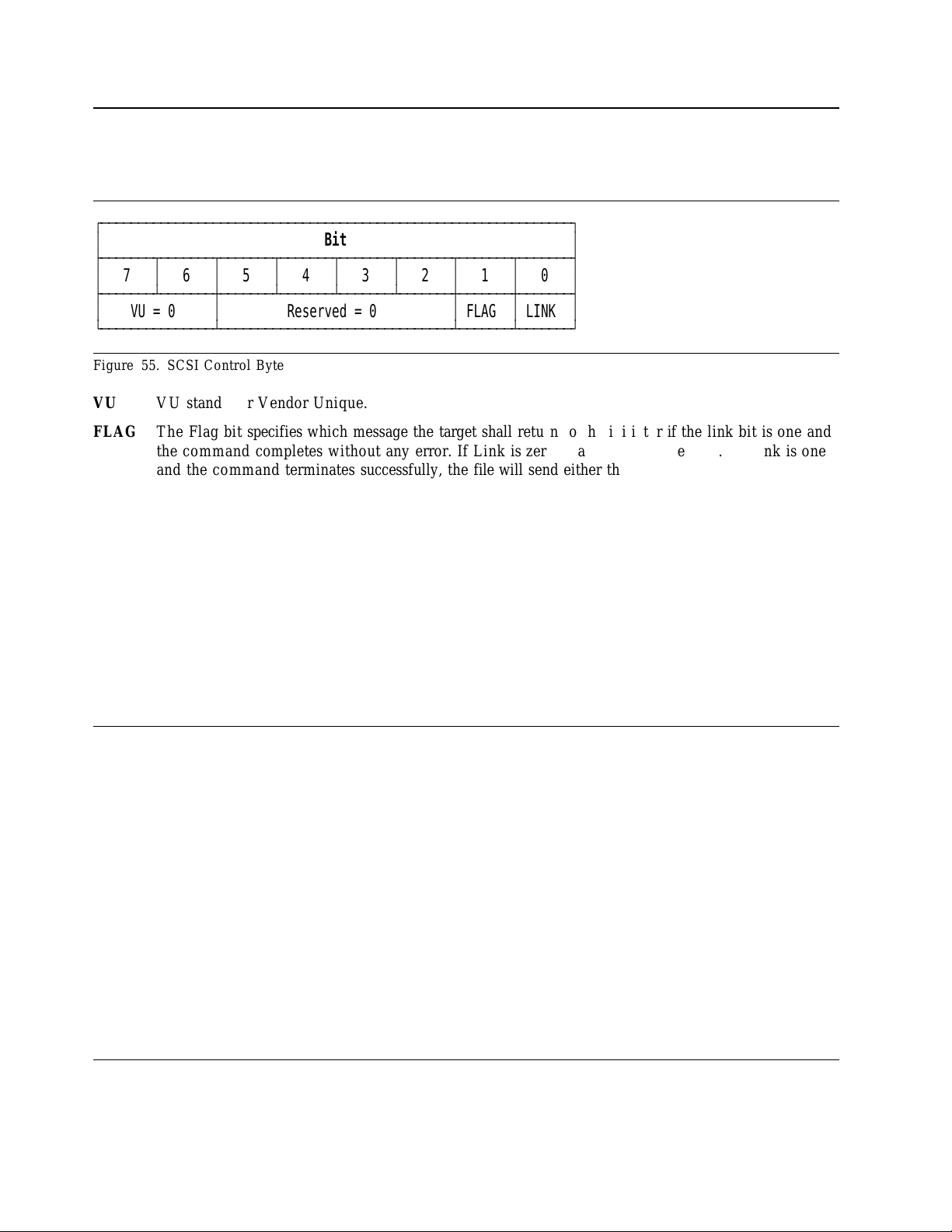
7.1 SCSI Control Byte
The Control Byte is t h e last byt e of every CDB. The format of this byte is shown below.
ЪДДДДДДДДДДДДДДДДДДДДДДДДДДДДДДДДДДДДДДДДДДДДДДДДДДДДДДДДДДДДДДД¿
³
ГДДДДДДДВДДДДДДДВДДДДДДДВДДДДДДДВДДДДДДДВДДДДДДДВДДДДДДДВДДДДДДД´
³
7
³
6
³
5
³
ГДДДДДДДБДДДДДДДЕДДДДДДДБДДДДДДДБДДДДДДДБДДДДДДДЕДДДДДДДЕДДДДДДД´
³
VU=0
АДДДДДДДДДДДДДДДБДДДДДДДДДДДДДДДДДДДДДДДДДДДДДДДБДДДДДДДБДДДДДДДЩ
Figure 55. SCSI Control Byte
VU VU stands for Vendor Unique.
FLAG Th e Flag bit specifies which message th e target shall return to the initiator if the link bit is o n e a nd
the command completes without any error. If Link is zero, Flag must also be zero. If Link is one
and the command terminates successfully, the file will send either the LINKED COMMAND
COMPLETE message (FLAG=0) or the LINKED COMMAND COMPLETE WITH FLAG
message (FLAG=1). Typically this bit is used t o cause a n interrupt in the initiator between linked
commands.
LINK Thi s bi t is set t o o n e to indicate that the initiator desires an automatic link to the n ex t command
upon successful completion of the current command. Upo n successful completion of the
command, the file will return INTERMEDIATE GOOD status and th en send on e of the tw o messages defined under Flag above.
³
Bit
4
³
3
Reserved = 0
³
³
2
³
1
³
0
³
³
FLAG³LINK
³
Upon unsuccessful completion of the command, the file will return CHECK CONDITION status
or RESERVATION CONFLICT status and t he n send the COMMAND COMPLETE message.
No further commands in the chain are executed.
7.2 Abbreviations
These abbreviations are used throughout the following sections:
LUN. Logical U n it Number. An encoded three bit identifier fo r the logical unit.
VU. Vendor Unique bits.
LBA. Logical Block Address.
RSVD. Reserved.
MSB. Most Significant bit.
LSB. Least Significant b i t.
7.3 Byte ordering conventions
In this specification, where it is no t explicitly stated, all multi-byte values are stored with the most significant
byt e first. For example in a 4 byte field byte 0 will contain the MSB a nd byte 3 the LSB.
64 OEM Spec. of DNES-3xxxxx Revision 1.2
Page 75

7.4 FORMAT UNIT (04)
ЪДДДДДДДВДДДДДДДДДДДДДДДДДДДДДДДДДДДДДДДДДДДДДДДДДДДДДДДДДДДДДДДДДДДДДДД¿
³³
³
Byte
ГДДДДДДДВДДДДДДДВДДДДДДДВДДДДДДДВДДДДДДДВДДДДДДДВДДДДДДДВДДДДДДД´
³³7³
ГДДДДДДДЕДДДДДДДБДДДДДДДБДДДДДДДБДДДДДДДБДДДДДДДБДДДДДДДБДДДДДДДБДДДДДДД´
³
0
³
ГДДДДДДДЕДДДДДДДДДДДДДДДДДДДДДДДВДДДДДДДВДДДДДДДВДДДДДДДДДДДДДДДДДДДДДДД´
³
1
³
ГДДДДДДДЕДДДДДДДДДДДДДДДДДДДДДДДБДДДДДДДБДДДДДДДБДДДДДДДДДДДДДДДДДДДДДДД´
³
2
³
ГДДДДДДДЕДДДДДДДДДДДДДДДДДДДДДДДДДДДДДДДДДДДДДДДДДДДДДДДДДДДДДДДДДДДДДДД´
³
3
³
(MSB) Interleave Factor
³
4
³
ГДДДДДДДЕДДДДДДДДДДДДДДДВДДДДДДДДДДДДДДДДДДДДДДДДДДДДДДДВДДДДДДДВДДДДДДД´
³
5
³
VU=0
АДДДДДДДБДДДДДДДДДДДДДДДБДДДДДДДДДДДДДДДДДДДДДДДДДДДДДДДБДДДДДДДБДДДДДДДЩ
Figure 56. FORMAT UNIT (04)
The F O R M A T command performs a physical formatting of the file media. This includes handling of defective sectors, a n d the overwriting of all dat a areas wi th a constant data pattern. (Reserved areas of the media
are n ot affected by t he FORMAT command.)
6
LUN
³
5
³
Command Code = 04h
³
³
Bit
4
³
3
³
2
³
1
³
0
FmtData³CmpList³Defect List Format
VU=0
(LSB)
Reserved = 0
³
FLAG³LINK
³
³
³
³
³
³
³
³
FmtData s et to one specifies that a Data Out phase follows the Command phase. FmtData set to zero
specifies that no Data Ou t phase follows.
CmpList set to one specifies that the GList (Grown Defect List) existing prior to the format not b e used
and is discarded. The Drive is formatted with PList and DList (if specified). DList becomes the new
GList.
Note: The file manages two internal defect lists and one external. The primary defect list (“P”List) is
created a t ti me of manufacture and cannot be altered. T he grown defect list (“G”List) is built after
manufacture by the Initiators use of the REASSIGN BLOCK command and the Automatic Reallocate
functions. T h e data defect list (“D”List) is an external list. It is supplied b y the initiator in the DATA
OUT phase of the F ORMAT UNIT command.
Defect List Format specifies the format of the defect descriptor transferred to t he Target w hen FmtData
bit is set to one. Th e Target supports three defect d e s c r iptor formats for t he F o r ma t Unit command as
following:
Format Description
000b Block format
100b Bytes From Index format
101b Physical Sector format
If the FmtData bit is set to zero this field must also be zero otherwise the command will complete with
a check condition with a sense key of illegal request and an additional sense code of invalid field in
CDB.
Interleave Factor m ay b e zero or one, either of which specifies an interleave of 1:1. Other Interleave
Factors are ignored because of th e extensive buffering implemented in the file.
SCSI COMMAND SET 65
Page 76

7.4.1 Defect List
ЪДДДДДДДВДДДДДДДДДДДДДДДДДДДДДДДДДДДДДДДДДДДДДДДДДДДДДДДДДДДДДДДДДДДДДДД¿
³³
³
Byte
ГДДДДДДДВДДДДДДДВДДДДДДДВДДДДДДДВДДДДДДДВДДДДДДДВДДДДДДДВДДДДДДД´
³³7³
ГДДДДДДДЕДДДДДДДБДДДДДДДБДДДДДДДБДДДДДДДБДДДДДДДБДДДДДДДБДДДДДДДБДДДДДДД´
³
0
³
ГДДДДДДДЕДДДДДДДВДДДДДДДВДДДДДДДВДДДДДДДВДДДДДДДВДДДДДДДВДДДДДДДВДДДДДДД´
³
1
³
FOV³DPRY³DCRT³STPF³IP=0³DSP=0³Immed³0
ГДДДДДДДЕДДДДДДДБДДДДДДДБДДДДДДДБДДДДДДДБДДДДДДДБДДДДДДДБДДДДДДДБДДДДДДД´
³
2
³
(MSB) Defect List Length
³
3
³
АДДДДДДДБДДДДДДДДДДДДДДДДДДДДДДДДДДДДДДДДДДДДДДДДДДДДДДДДДДДДДДДДДДДДДДДЩ
Figure 57. F o rm a t of Defect List Header. F orm at of the defect list header sent during the data out phase when
FmtData set to one.
The Target has a limited implementation of the F or m at Option bits located in Bits 2 through 7 of Byte 1 of
the Defect List Header (See Figure 57). If the Initiator attempts t o select any function n ot implemented by
the Target, the Target terminate t he command with Check Condition S t a t us . Th e sense key is set to Illegal
Request a nd t he additional sense code is set to Invalid Field in Parameter List.
FOV (Format Options Valid) bit of zero causes the Target t o verify that the setting for th e DPRY
(Disable Primary), DCRT (Disable Certification), STPF (Stop Forma t), I P (Initialize Pattern), and DS P
(Disab l e Saving Parameters) bits are zero. If any of these bits are no t zero, the Target terminates the
command with Check Condition Stat u s . The sense key is set to Illegal Request an d the additional sense
code is set to Invalid Field in Parameter List.
6
³
5
³
Bit
4
³
3
Reserved = 0
³
³
2
³
1
³
0
³
³
³
³
(LSB)
³
Note: When F OV bit is one there are three combinations of the DPRY, DCRT, STPF, IP and DSP
bits allowed. A n y other combinations return a Check Condition Sta t u s With a sense key of Illegal
Request a nd a n additional sense code of Invalid Field In Parameter List. The supported combination
are:
DPRY=0 DCRT=1 STPF=1 IP=0 DSP=0
DPRY=1 DCRT=1 STPF=1 IP=0 DSP=0
DPRY=0 DCRT=0 STPF=1 IP=0 DSP=0
DPRY (Disable Primary) bit set to zero indicates that the Target does no t use portions of the medium
identified as defective in the primary defect PList for Initiator addressable logical blocks. If th e Target
cannot locate th e PList or it cannot determine whether a PList exists, the tar g e t terminates the F o r m at
Unit command as described for STPF=1. A DPRY bit of one indicates that the Target does n o t use
the Plist to identify defective areas of the medium. T he Plist is not deleted.
DCRT (Disable Certification) bit of ZERO indicates that the Target performs a medium certification
operation and generates a Certification List (CList) a nd th e Target adds the Clist to the Glist. A DCRT
bit of on e indicates that the Target does n o t generate a CList (Certification List) nor perform a certification process while executing the For ma t Un it Command.
Note: Since the DCRT bit is part of the Data Ou t phase that follows th e format command, the
FCERT bit in Mode Page 0 is provided to control certification when th e format command is issued wi t h
no Data Out phase. If a format command is issued wit h a Data Ou t phase t hen FCERT is ignored.
STPF (Stop Format) bit must be set to one. If one or bo th of the following conditions occurs, the
Target terminates the F o r m a t Uni t command with Check Condition S ta t u s . Th e sense key is set to
Medium Error an d th e additional sense code is set to either Defect List N ot Found if the first condition
occurred, o r Defect List Error if the second condition occurred.
66 OEM Spec. of DNES-3xxxxx Revision 1.2
Page 77

− T he Target cannot locate a required defect list no r determine that the list exists.
− T h e Target encounters an unrecoverable error while accessing a required defect list.
IP (Initialization Pattern) bit must be set to zero. Th e Target initializes all d ata w i th zeros.
DSP ( D is a bl e Saving Parameters) bit must be set to zero. Th e Target saves all the Mode Select savable
parameters during the format operation.
Immed (Immediate) bit set to zero requests that status be returned at the end of the format operation.
An immediate bit set t o one requests that status b e returned immediately. Good Status is retu rned following t he CDB validation and transfer of data in t he Data Ou t phase. If the immediate format operation terminates in error, Deferred Error Sense da t a is generated. With the immediate bit set t o one, the
Link bit must be set to zero.
7.4.2 Defect Descriptor
Th e Defect List Length field specifies the total length in bytes of t he defect descriptors that follow. Th e
Target has an implementation limitation for number of defect descr i p t o r s . Th e number of defect descriptor
shall b e less than 128. Th e defect list length must be equal t o four times the number of defect descriptors t o
follow for t h e BLOCK format, or eight times the number of defect descriptors to follow for th e BYTES
FRO M INDEX and PHYSICAL SECTOR format, otherwise the command is terminated with Check Con-
dition S t a t u s Th e sense key is set to Illegal Request an d th e additional sense code is set to Invalid Field In
Parameter List. Th e defect descriptors must specify the defect based on th e current F o r m a t Device parame-
ters r eported by the Mode Sense command.
The Target supports three Defect List formats.
7.4.2.1 Block Format
The Block format of th e defect list supported by the file is by logical block where th e location of defective
sectors is given b y their LBA.
ЪДДДДДДДВДДДДДДДДДДДДДДДДДДДДДДДДДДДДДДДДДДДДДДДДДДДДДДДДДДДДДДДДДДДДДДД¿
³³
³
Byte
ГДДДДДДДВДДДДДДДВДДДДДДДВДДДДДДДВДДДДДДДВДДДДДДДВДДДДДДДВДДДДДДД´
³³7³
ГДДДДДДДЕДДДДДДДБДДДДДДДБДДДДДДДБДДДДДДДБДДДДДДДБДДДДДДДБДДДДДДДБДДДДДДД´
0
³
³
³
1
³
2
³
3
ГДДДДДДДЕДДДДДДДДДДДДДДДДДДДДДДДДДДДДДДДДДДДДДДДДДДДДДДДДДДДДДДДДДДДДДДД´
³
4n -
³
4n+3
АДДДДДДДБДДДДДДДДДДДДДДДДДДДДДДДДДДДДДДДДДДДДДДДДДДДДДДДДДДДДДДДДДДДДДДДЩ
Figure 58. Defect Descriptor - Block Format. Format of the defect list sent during the data out phase when FmtData
(MSB)
³
³³
³
³
³³
set to one.
6
³
5
³
Defective Logical Block Address
Defective Logical Block Address n
Bit
4
³
3
³
2
³
1
³
(LSB)
³
³
0
³
³
³
³
7.4.2.2 Bytes From Index Format
Each defect de scrip t o r for the Bytes From Index format specifies that the sector containing this byte be
marked defective. The defect d e s c ripto r is comprised of the cylinder number of the defect, the head number
of the defect, and the defect bytes from index.
SCSI COMMAND SET 67
Page 78

ЪДДДДДДДВДДДДДДДДДДДДДДДДДДДДДДДДДДДДДДДДДДДДДДДДДДДДДДДДДДДДДДДДДДДДДДД¿
³³
³
Byte
ГДДДДДДДВДДДДДДДВДДДДДДДВДДДДДДДВДДДДДДДВДДДДДДДВДДДДДДДВДДДДДДД´
³³7³
ГДДДДДДДЕДДДДДДДБДДДДДДДБДДДДДДДБДДДДДДДБДДДДДДДБДДДДДДДБДДДДДДДБДДДДДДД´
³
0
³
(MSB)
³
1
³
³
2
³
³ ГДДДДДДДДДДДДДДДДДДДДДДДДДДДДДДДДДДДДДДДДДДДДДДДДДДДДДДДДДДДДДДД´
³
3
³
³ ГДДДДДДДДДДДДДДДДДДДДДДДДДДДДДДДДДДДДДДДДДДДДДДДДДДДДДДДДДДДДДДД´
³
4
³
(MSB)
³
5
³
³
6
³³
³
7
³
ГДДДДДДДЕДДДДДДДДДДДДДДДДДДДДДДДДДДДДДДДДДДДДДДДДДДДДДДДДДДДДДДДДДДДДДДД´
³
8n -
³
³
8n+7
³³
АДДДДДДДБДДДДДДДДДДДДДДДДДДДДДДДДДДДДДДДДДДДДДДДДДДДДДДДДДДДДДДДДДДДДДДДЩ
Figure 59. Defect Descriptor - Bytes From Index Format. Fo rmat of the defect list sent during the data out phase
when FmtData set to one.
6
³
5
³
Cylinder Number of Defect
Head Number of Defect
Defect Bytes from Index
Defect Descriptor n
Bit
4
³
3
³
2
³
1
³
(LSB)
(LSB)
³
0
³
³
³
³
³
³
³
³
³
7.4.2.3 Physical Sector Format
Each defect de scrip t o r for the Physical Sector format specifies a defect that is the length of a sector. T he
defect d e s cript o r is comprised of the cylinder number of the defect, the head number of the defect, and t he
defect sector number.
ЪДДДДДДДВДДДДДДДДДДДДДДДДДДДДДДДДДДДДДДДДДДДДДДДДДДДДДДДДДДДДДДДДДДДДДДД¿
³³
³
Byte
ГДДДДДДДВДДДДДДДВДДДДДДДВДДДДДДДВДДДДДДДВДДДДДДДВДДДДДДДВДДДДДДД´
³³7³
ГДДДДДДДЕДДДДДДДБДДДДДДДБДДДДДДДБДДДДДДДБДДДДДДДБДДДДДДДБДДДДДДДБДДДДДДД´
0
³
³
³
1
³
2
³ ГДДДДДДДДДДДДДДДДДДДДДДДДДДДДДДДДДДДДДДДДДДДДДДДДДДДДДДДДДДДДДДД´
³
3
³ ГДДДДДДДДДДДДДДДДДДДДДДДДДДДДДДДДДДДДДДДДДДДДДДДДДДДДДДДДДДДДДДД´
³
4
³
5
³
6
³
7
ГДДДДДДДЕДДДДДДДДДДДДДДДДДДДДДДДДДДДДДДДДДДДДДДДДДДДДДДДДДДДДДДДДДДДДДДД´
³
8n -
³
8n+7
АДДДДДДДБДДДДДДДДДДДДДДДДДДДДДДДДДДДДДДДДДДДДДДДДДДДДДДДДДДДДДДДДДДДДДДДЩ
Figure 60. Defect Descriptor - Physical Sector Format. Format of the defect list sent during the data out phase when
(MSB)
³
³
³
³
(MSB)
³
³³
³
³
³³
FmtData set to one.
6
³
5
³
Cylinder Number of Defect
Head Number of Defect
Defective Sector Number
Defect Descriptor n
Bit
4
³
3
³
2
³
1
³
(LSB)
(LSB)
³
³
0
³
³
³
³
³
³
³
³
68 OEM Spec. of DNES-3xxxxx Revision 1.2
Page 79

7.5 INQUIRY (12)
ЪДДДДДДДВДДДДДДДДДДДДДДДДДДДДДДДДДДДДДДДДДДДДДДДДДДДДДДДДДДДДДДДДДДДДДДД¿
³³
³
Byte
ГДДДДДДДВДДДДДДДВДДДДДДДВДДДДДДДВДДДДДДДВДДДДДДДВДДДДДДДВДДДДДДД´
³³7³
ГДДДДДДДЕДДДДДДДБДДДДДДДБДДДДДДДБДДДДДДДБДДДДДДДБДДДДДДДБДДДДДДДБДДДДДДД´
³
0
³
ГДДДДДДДЕДДДДДДДДДДДДДДДДДДДДДДДВДДДДДДДДДДДДДДДДДДДДДДДВДДДДДДДВДДДДДДД´
³
1
³
ГДДДДДДДЕДДДДДДДДДДДДДДДДДДДДДДДБДДДДДДДДДДДДДДДДДДДДДДДБДДДДДДДБДДДДДДД´
³
2
³
ГДДДДДДДЕДДДДДДДДДДДДДДДДДДДДДДДДДДДДДДДДДДДДДДДДДДДДДДДДДДДДДДДДДДДДДДД´
³
3
³
ГДДДДДДДЕДДДДДДДДДДДДДДДДДДДДДДДДДДДДДДДДДДДДДДДДДДДДДДДДДДДДДДДДДДДДДДД´
³
4
³
ГДДДДДДДЕДДДДДДДДДДДДДДДВДДДДДДДДДДДДДДДДДДДДДДДДДДДДДДДВДДДДДДДВДДДДДДД´
³
5
³
VU=0
АДДДДДДДБДДДДДДДДДДДДДДДБДДДДДДДДДДДДДДДДДДДДДДДДДДДДДДДБДДДДДДДБДДДДДДДЩ
Figure 61. INQUIRY (12)
The INQUIRY command requests t he parameters of the target t o be sent t o t he initiator.
6
LUN
³
5
³
Command Code = 12h
³
³
Bit
4
³
3
³
Reserved = 0
Page Code
Reserved = 0
Allocation Length
Reserved = 0
2
³
1
³
CmdDt=0³EVPD
³
FLAG³LINK
³
³
0
³
³
³
³
³
³
³
An EVPD bit of one specifies that the file shall return the vital product data page identified b y the Page
Code field in the CDB.
return.
EVPD PAGE
CODE
0 0 The file returns the standard INQUIRY data.
0 N o n Zero The file returns CHECK CONDITION status with the sense key of
1 Supported The file returns the vital product data of page code requested.
1 Unsupported The file returns CHECK CONDITION status with t he sense key of
Allocation Length specifies the number of bytes that the initiator has allocated for INQUIRY data to be
returned. A n allocation length of zero implies that n o data is to be returned. The file will terminate the
DATA IN phase when all available INQUIRY data has been transferred or w he n allocation length bytes
have been transferred, whichever is less.
If an INQUIRY command is received from an initiator with a pending unit attention condition (before the
target reports CHECK CONDITION status), the file processes the INQUIRY command. Th e unit attention condition is not cleared by this action.
1
Page code specifies which page of vital product data information the file shall
Description
ILLEGAL REQUEST and the additional sense code of INVALID FIELD
IN CDB.
ILLEGAL REQUEST and the additional sense code of INVALID FIELD
IN CDB.
1
The available V PD pages a r e defined in the addendum provided for each different file model in the section entitled
Inquiry Data Format.
SCSI COMMAND SET
69
Page 80

7.6 Inquiry data
Fields w it h a value shown inside quotes (e.g. Value = 'xyz') are character fields. A value not in quotes is a
numeric value. Character fields are alpha-numeric and represented in either ASCII or EBCDIC as stated.
70 OEM Spec. of DNES-3xxxxx Revision 1.2
Page 81

7.6.1 Inquiry Data Format - EVPD = 0
Figure 62 shows the data format.
ЪДДДДДДДДДДДДДДДДДДДДДДДДДДДДДДДДДДДДДДДДДДДДДДДДДДДДДДД¿
³
Byte³76543210
ЪДДДДДДДДЕДДДДДДДДДДДДДДДДДДДДВДДДДДДДДДДДДДДДДДДДДДДДДДДДДДДДДДД´
³
0
³
Qualifier = 0
ГДДДДДДДДЕДДДДДДВДДДДДДДДДДДДДБДДДДДДДДДДДДДДДДДДДДДДДДДДДДДДДДДД´
³
1
³
RMB=0
³
ГДДДДДДДДЕДДДДДДБДДДДДДВДДДДДДДДДДДДДДДДДДДДВДДДДДДДДДДДДДДДДДДДД´
³
2
³
ISO=0
ГДДДДДДДДЕДДДДДДВДДДДДДЕДДДДДДВДДДДДДВДДДДДДБДДДДДДДДДДДДДДДДДДДД´
³
3
³
RSVD³TrmTsk³Norm³RSVD
³³
ГДДДДДДДДЕДДДДДДБДДДДДДБДДДДДДБДДДДДДБДДДДДДДДДДДДДДДДДДДДДДДДДДД´
³
4
ГДДДДДДДДЕДДДДДДДДДДДДДДДДДДДДДДДДДДДДДДДДДДДДДДДДДДДДДДДДДДДДДДД´
³
5
ГДДДДДДДДЕДДДДДДВДДДДДДВДДДДДДВДДДДДДВДДДДДДВДДДДДДВДДДДДДВДДДДДД´
³
6
³³
ГДДДДДДДДЕДДДДДДЕДДДДДДЕДДДДДДЕДДДДДДЕДДДДДДЕДДДДДДЕДДДДДДЕДДДДДД´
7
³
³³
ГДДДДДДДДЕДДДДДДБДДДДДДБДДДДДДБДДДДДДБДДДДДДБДДДДДДБДДДДДДБДДДДДД´
8Ä15
³
ГДДДДДДДДЕДДДДДДДДДДДДДДДДДДДДДДДДДДДДДДДДДДДДДДДДДДДДДДДДДДДДДДД´
³16Ä31³
ГДДДДДДДДЕДДДДДДДДДДДДДДДДДДДДДДДДДДДДДДДДДДДДДДДДДДДДДДДДДДДДДДД´
³32Ä35³
ГДДДДДДДДЕДДДДДДДДДДДДДДДДДДДДДДДДДДДДДДДДДДДДДДДДДДДДДДДДДДДДДДД´
³36Ä43³
ГДДДДДДДДЕДДДДДДДДДДДДДДДДДДДДДДДДДДДДДДДДДДДДДДДДДДДДДДДДДДДДДДД´
³44Ä95³
ГДДДДДДДДЕДДДДДДДДДДДДДДДДДДДДДДДДДДДДДДДДДДДДДДДДДДДДДДДДДДДДДДД´
³
96-145
ГДДДДДДДДЕДДДДДДДДДДДДДДДДДДДДДДДДДДДДДДДДДДДДДДДДДДДДДДДДДДДДДДД´
³
146-163
АДДДДДДДДБДДДДДДДДДДДДДДДДДДДДДДДДДДДДДДДДДДДДДДДДДДДДДДДДДДДДДДДЩ
=0³=0³ACA=0³=0
³
³
³
RSVD³EncSer³RSVD³MultiP³MChngr³ACKREQ³Addr32³Addr16
=0³=0³=0³=0³=0
³
REL_A³Wb_32³Wb_16³Sync³Link³TTD³CmdQu³RSVD
=0³=0
³
³
³
³
Additional Length = 159 (9Fh)
Reserved = 0
³³
Vendor ID = 'IBM ' (ASCII)
Product ID (ASCII)
Product Revision Level (ASCII)
Unit Serial Number (ASCII)
Reserved = 0
Copyright Notice (ASCII)
Reserved = 0
BIT
³
Peripheral Device Type = 0
DeviceÄType Modifier = 0
ECMA = 0
³
³
³
Response Data Format
Q=0³=0
³
=1³=1³=0
ANSI = 3
=2
³³
³
=1³=0
³
³
³
³
³
³
³
³
³
³
³
³
³
³
³
³
³
³
³
Figure 62. INQUIRY Data - EVPD = 0
Qualifier is set to zero to indicate that the L U N specified in the Command Block is currently supported.
Qualifier is set t o 011b whe n the LUN specified in th e Command Block is n o t present.
Peripheral Device Type is set to zero t o indicate that the device is a Direct-Access.
Peripheral Dev. Type is set to 1 Fh when the L U N specified in the Command Block is no t present.
Removal Media Bit (RMB) is always set to zero to indicate n o removal media exist.
Device-Type Modifier is set to zero.
2
For all commands, except inquiry a n d request sense, if an invalid lu n is specified a check condition will be returned.
SCSI COMMAND SET
2
71
Page 82

ISO is set to zero to indicate that this product does n o t claim compliance t o th e International Organiza-
tion for Standardization (ISO) version of SCSI (ISO D P 9316).
ECMA is set to zero to indicate that this product does n o t claim compliance t o t he E u r opean Computer
Manufacturers Association ( ECMA) version of SCSI (ECMA-111).
ANSI indicates t he level of the ANSI standard that is supported by the product. T he file supports ANSI
SCSI version 3.
TrmTsk (Terminate Task) filed of 0 indicates th e Target does no t support the TERMINATE TASK
task management function as defined in t h e SAM.
NormACA (Normal ACA) field of 0 indicates th e device server does not support setting the NACA bit
to one in the Control Byte of the CDB as defined in th e SAM.
Response Data Format is set to two to indicate that the Inquiry Data F ormat as specified in ANSI SCSI
version 2 is supported by the file.
Additional Length indicates th e number of bytes of inquiry information that follows.
EncSer (Enclosure Services) b it of 0 indicates that the Target does not contain an embedded enclosure
service component.
MultiP (MultiPort) bit of 0 indicates that the Target has a single port and does n o t implement multiport
requirements.
MChngr (Medium Changer) bit is only supported when the RMB bit is one.
ACKREQQ (ACKQ/REQQ) bit of 0 indicates that the Target does no t support a request and acknowl-
edge data transfer handshake on a Q cable.
Addr32 (Wide SCSI Address 32) bi t of 0 indicates that the Target does n o t support 32 bit wide SCSI
Addresses.
Addr16 (Wide SCSI Address 16) bi t of 1 indicates that the Target supports 16 bit wide SCSI Addresses.
REL_A is set to zero to indicate that the file does not support 'Relative Address Mo de'.
Wb_32 is set to zero to indicate that the file does no t support 32-bit wide da t a transfers.
Wb_16 is set to one to indicate that the file supports 16-bit wide dat a transfers. Wb_16 is set t o zero t o
indicate that the file does n ot support 16-bit wide dat a transfers.
Sync is set t o o n e to indicate that the file supports synchronous data transfer.
Link is set t o o n e to indicate that the file supports linked commands.
TTD is set to zero to indicate that the file does no t support the CONTINUE I/O PROCESS and
TARGET TRANSFER DISABLE message for this logical unit.
CmdQu is set t o o n e to indicate that the file supports command queuing. CmdQu is set to zero to
indicate that the file does n ot support command queuing.
SftRe is set to zero to indicate that the target supports Hard Reset only.
Vendor ID is 'IBM' padded with ASCII blanks.
Product ID is specified in ASCII character.
Product ID DNES-309170 DNES-318350 DNES-309170W/Y DNES-318350W/Y
Maximum LBA 17916239 35843669 17916239 35843669
Number of Blocks 17916240 35843670 17916240 35843670
Figure 63. Product ID vs. Formatted Capacity
72 OEM Spec. of DNES-3xxxxx Revision 1.2
Page 83

Product Revision Level indicates th e level of microcode. I t indicates RAM microcode level.
Unit Serial Number contains the file serial number.
SCSI COMMAND SET 73
Page 84

7.6.2 Inquiry Data Format - EVPD = 1 - Page Code = 00
ЪДДДДДДДДДДДДДДДДДДДДДДДДДДДДДДДДДДДДДДДДДДДДДДДДДДДДДДД¿
³
Byte³76543210
ЪДДДДДДДДЕДДДДДДДДДДДДДДДДДДДДВДДДДДДДДДДДДДДДДДДДДДДДДДДДДДДДДДД´
³
0
³
Qualifier = 0
ГДДДДДДДДЕДДДДДДДДДДДДДДДДДДДДБДДДДДДДДДДДДДДДДДДДДДДДДДДДДДДДДДД´
³
1
³
ГДДДДДДДДЕДДДДДДДДДДДДДДДДДДДДДДДДДДДДДДДДДДДДДДДДДДДДДДДДДДДДДДД´
³
2
³
ГДДДДДДДДЕДДДДДДДДДДДДДДДДДДДДДДДДДДДДДДДДДДДДДДДДДДДДДДДДДДДДДДД´
³
3
³
ГДДДДДДДДЕДДДДДДДДДДДДДДДДДДДДДДДДДДДДДДДДДДДДДДДДДДДДДДДДДДДДДДД´
³
4
³
АДДДДДДДДБДДДДДДДДДДДДДДДДДДДДДДДДДДДДДДДДДДДДДДДДДДДДДДДДДДДДДДДЩ
Figure 64. INQUIRY DATA - EVPD = 1 (Page Code = 00)
Qualifier is set to zero to indicate that the L U N specified in the Command Block is currently supported.
Peripheral Device Type is set to zero t o indicate that the device is a Direct-Access.
Page Code is set to 0, a n d this field contains the same value as in the page code field of the INQUIRY
command descriptor block.
BIT
³
Peripheral Device Type = 0
Page Code = 00h
Reserved = 0
Page Length = 01h
Supported Page Code = 80h
³
³
³
³
³
³
³
Page length specifies the length of the following page data.
The Supported Page Code field contains th e Page Codes supported by the target. The list is ascending
order.
74 OEM Spec. of DNES-3xxxxx Revision 1.2
Page 85

7.6.3 Inquiry Data Format - EVPD = 1 - Page Code = 80h
ЪДДДДДДДДДДДДДДДДДДДДДДДДДДДДДДДДДДДДДДДДДДДДДДДДДДДДДДД¿
³
Byte³76543210
ЪДДДДДДДДЕДДДДДДДДДДДДДДДДДДДДВДДДДДДДДДДДДДДДДДДДДДДДДДДДДДДДДДД´
³
0
³
Qualifier = 0
ГДДДДДДДДЕДДДДДДДДДДДДДДДДДДДДБДДДДДДДДДДДДДДДДДДДДДДДДДДДДДДДДДД´
³
1
³
ГДДДДДДДДЕДДДДДДДДДДДДДДДДДДДДДДДДДДДДДДДДДДДДДДДДДДДДДДДДДДДДДДД´
³
2
³
ГДДДДДДДДЕДДДДДДДДДДДДДДДДДДДДДДДДДДДДДДДДДДДДДДДДДДДДДДДДДДДДДДД´
³
3
³
ГДДДДДДДДЕДДДДДДДДДДДДДДДДДДДДДДДДДДДДДДДДДДДДДДДДДДДДДДДДДДДДДДД´
³
4-19
АДДДДДДДДБДДДДДДДДДДДДДДДДДДДДДДДДДДДДДДДДДДДДДДДДДДДДДДДДДДДДДДДЩ
Figure 65. INQUIRY DATA - EVPD = 1 (Page Code = 80h)
³
Qualifier is set to zero to indicate that the L U N specified in the Command Block is currently supported.
Peripheral Device Type is set to zero t o indicate that the device is a Direct-Access.
Page Code is set to 80h, an d this field contains the same value as in the page code field of the
INQUIRY command descriptor block.
BIT
³
Peripheral Device Type = 0
Page Code = 80h
Reserved = 0
Page Length = 16 (10h)
Serial Number (ASCII)
³
³
³
³
³
³
³
Page length is set to 16, and this field specifies the length of the following page data.
Serial Number gives the drive serial number.
SCSI COMMAND SET 75
Page 86

7.7 LOG SELECT (4C)
ЪДДДДДДДВДДДДДДДДДДДДДДДДДДДДДДДДДДДДДДДДДДДДДДДДДДДДДДДДДДДДДДДДДДДДДДД¿
³³
³
Byte
ГДДДДДДДВДДДДДДДВДДДДДДДВДДДДДДДВДДДДДДДВДДДДДДДВДДДДДДДВДДДДДДД´
³³7³
ГДДДДДДДЕДДДДДДДБДДДДДДДБДДДДДДДБДДДДДДДБДДДДДДДБДДДДДДДБДДДДДДДБДДДДДДД´
³
0
³
ГДДДДДДДЕДДДДДДДДДДДДДДДДДДДДДДДВДДДДДДДДДДДДДДДДДДДДДДДВДДДДДДДВДДДДДДД´
³
1
³
ГДДДДДДДЕДДДДДДДДДДДДДДДВДДДДДДДБДДДДДДДДДДДДДДДДДДДДДДДБДДДДДДДБДДДДДДД´
³
2
³
ГДДДДДДДЕДДДДДДДДДДДДДДДБДДДДДДДДДДДДДДДДДДДДДДДДДДДДДДДДДДДДДДДДДДДДДДД´
³
3
³³
³
4
³
³
5
³³
³
6
³³
ГДДДДДДДЕДДДДДДДДДДДДДДДДДДДДДДДДДДДДДДДДДДДДДДДДДДДДДДДДДДДДДДДДДДДДДДД´
³
7
³
(MSB) Parameter List Length = 0
³
8
³
ГДДДДДДДЕДДДДДДДДДДДДДДДДДДДДДДДДДДДДДДДДДДДДДДДДДДДДДДДВДДДДДДДВДДДДДДД´
³
9
³
АДДДДДДДБДДДДДДДДДДДДДДДДДДДДДДДДДДДДДДДДДДДДДДДДДДДДДДДБДДДДДДДБДДДДДДДЩ
PC
6
LUN
³
5
³
Reserved = 0
³
Command Code = 4Ch
³
Bit
4
³
Reserved = 0
Reserved = 0
Reserved = 0
3
³
2
³
1
³
0
³
PCR³SP
(LSB)
³
FLAG³LINK
³
³
³
³
³
³
³
³
³
Figure 66. LO G SELECT (4C)
The LO G SELECT command provides a means for the initiator to clear statistical information maintained
by t he drive and re p orte d via the Log Sense command.
PCR T he Parameter Code Reset determines whether the Log Sense parameters will be cleared and unit
attention posted for all other initiators. A value of 1 indicates that the parameters should be cleared,
while a value of zero (except w h e n PC = 11b) indicates that the parameters should n ot be cleared.
SP Th e Save Parameters bit value of zero indicates that the page parameters n ot be saved. A value of 1
indicates that the page parameters that are saveable s hould be saved after they have been changed.
PC T h e Page Control field defines the ty pe of parameters t o be selected. T he P C field set to 11b (and
PC R is then a don't care) indicates that the Default Cumulative values are set to their default values of
0. If the PC field is set to 01b and PCR is set to 1 the Current Cumulative values are also set to their
default values.
As the file does n o t support the threshold pages any other value in this field will cause the command to
end with a CHECK CONDITION with a sense key of illegal request and an additional sense code of
invalid field in CDB.
Parameter List Length The Parameter List Length must be zero to indicate that no data is transferred
from t he initiator to t he target during the potential DATA OUT phase.
If one or more fields of the CDB are not set correctly t h e command will be terminated with a CHECK
CONDITION status. T h e Sense K e y shall b e set to Illegal Request and the additional sense code set t o
Invalid Field in CDB.
The Log Select command will reset the counter variables t o their default values of zero. These variables are
listed i n the Log Sense command.
Th e target generates a unit attention condition, to indicate that parameters have changed, for all initiators
except t he one that issued the Log Select command.
76 OEM Spec. of DNES-3xxxxx Revision 1.2
Page 87

7.8 LOG SENSE (4D)
ЪДДДДДДДВДДДДДДДДДДДДДДДДДДДДДДДДДДДДДДДДДДДДДДДДДДДДДДДДДДДДДДДДДДДДДДД¿
³³
³
Byte
ГДДДДДДДВДДДДДДДВДДДДДДДВДДДДДДДВДДДДДДДВДДДДДДДВДДДДДДДВДДДДДДД´
³³7³
ГДДДДДДДЕДДДДДДДБДДДДДДДБДДДДДДДБДДДДДДДБДДДДДДДБДДДДДДДБДДДДДДДБДДДДДДД´
³
0
³
ГДДДДДДДЕДДДДДДДДДДДДДДДДДДДДДДДВДДДДДДДДДДДДДДДДДДДДДДДВДДДДДДДВДДДДДДД´
³
1
³
ГДДДДДДДЕДДДДДДДДДДДДДДДВДДДДДДДБДДДДДДДДДДДДДДДДДДДДДДДБДДДДДДДБДДДДДДД´
³
2
³
ГДДДДДДДЕДДДДДДДДДДДДДДДБДДДДДДДДДДДДДДДДДДДДДДДДДДДДДДДДДДДДДДДДДДДДДДД´
³
3
³
³
4
³³
ГДДДДДДДЕДДДДДДДДДДДДДДДДДДДДДДДДДДДДДДДДДДДДДДДДДДДДДДДДДДДДДДДДДДДДДДД´
³
5
³
(MSB) Parameter Pointer = 0
³
6
³
ГДДДДДДДЕДДДДДДДДДДДДДДДДДДДДДДДДДДДДДДДДДДДДДДДДДДДДДДДДДДДДДДДДДДДДДДД´
³
7
³
(MSB) Allocation Length
³
8
³
ГДДДДДДДЕДДДДДДДДДДДДДДДДДДДДДДДДДДДДДДДДДДДДДДДДДДДДДДДВДДДДДДДВДДДДДДД´
³
9
³
АДДДДДДДБДДДДДДДДДДДДДДДДДДДДДДДДДДДДДДДДДДДДДДДДДДДДДДДБДДДДДДДБДДДДДДДЩ
PC
6
LUN
³
5
³
Reserved = 0
³
Command Code = 4Dh
³
Bit
4
³
Reserved = 0
Reserved = 0
3
³
2
Page Code
³
1
³
³
PPC=0³SP
(LSB)
(LSB)
³
FLAG³LINK
0
³
³
³
³
³
³
³
³
³
³
³
Figure 67. LO G SENSE (4D)
The L O G SENSE command allows the initiator t o retrieve the statistical data about the drive.
PPC (Parameter Pointer Control) bit must be set to zero. T hi s specifies that the drive start transferring
data starting from the field specified in the parameter pointer field for the number of bytes specified by
the allocation length. If the PPC bit is set to 1, CHECK CONDITION status is returned with a Sense
Key of Illegal Request and additional sense code of Invalid Field in CDB.
SP (Save Parameters) bit set to 0 specifies that the drive does not save any log parameters. If set t o 1 all
page parameters that are savable (those pages denoted by a DS = 0 in t he parameter header control
byte) are saved.
PC (Page Control) field defines th e typ e of parameters to be selected. This field must be set to 01b to
specify the current cumulative values or 11b t o specify the default cumulative values.
As the file does n o t support the threshold pages any other value in this field will cause the command to
end with a CHECK CONDITION with a sense key of illegal request and an additional sense code of
invalid field in CDB.
Page Code field identifies which page is being requested. This field must be set to the values indicated i n
Page 0. If the Page Code value is invalid a CHECK CONDITION status is returned with a Sense Key
of Illegal Request and additional sense code of Invalid Field in CDB.
Parameter Pointer Field specifies the beginning field for the transfer. Th i s field must be set to 0000h. If
the Parameter Pointer Field is no t zero a CHECK CONDITION status is returned with a Sense Ke y of
Illegal Request and additional sense code of Invalid Field in CDB.
Allocation Length field specifies the maximum number of bytes t he Initiator has allocated for re tur ne d
Log Sense Data. N o bytes are transferred if the length is zero. T h is condition is not considered a n error.
The target terminates th e Data In phase w hen all available L o g Sense d a t a h a s been transferred or when
the number of bytes equals the allocation length, whichever is less.
SCSI COMMAND SET 77
Page 88

7.8.1 Log Page parameters
Each log page begins w it h a four-byte page header followed by zero or more variable-length log parameters.
Page Header Page Code field identifies which log page is being transferred.
The Page Length field specifies the length in bytes of the following log parameters.
Log Parameters Each log parameter begins wit h a four-bytes parameter header followed by on e or more
bytes of parameter value data.
The Parameter Code field identifies which log parameter is being transferred for that log page.
The Parameter Control field, or 3rd byte of each parameter header contains several fields.
− DU T h e Disable Update bit is set to 0 which indicates that the drive updates the log parameter
value to reflect events that should be noted by that parameter.
− DS The Disable Save bit is set to 1 to indicate t h e parameter is non-saveable and is set to 0 to
indicate t h e parameter is saveable.
− TSD Th e Target Save Disable bit is set t o zero which indicates the drive provides a target defined
method for saving log parameters.
− ETC The enable Threshold Comparison bit is set to 0 which indicates t h e drive does no t perform
comparisons between cumulative and any threshold values.
− LBIN Th e List Binary bit is set to 1 for vendor unique pages whose parameters lists ar e in binary
format, n ot ASCII. This bit is reserved a nd set t o 0 for all other pages.
− LP Th e List Parameter bit is set to 0 for parameters that are data counters. The LP bit is set to 1 for
parameters that are lists.
78 OEM Spec. of DNES-3xxxxx Revision 1.2
Page 89

7.8.2 Log Sense Page 0
Byte 7 6 5 4 3 2 1 0
0 Reserved Page code = 0
1 Reserved
2-3 Page Length = 000Bh (Number of Pages Supported)
4 First supported page 0h
5 Second supported page 2h
6 Third supported page 3h
7 Four t h supported page 5h
8 Fifth supported page 6h
9 Sixth supported page 2Fh
10 Sixth supported page 30h
11 Sixth supported page 31h
12 Sixth supported page 32h
13 Seventh supported page 3E h
14 Eighth supported page 3 Fh
Page 0 indicates the supported log sense pages. T h i s page is used t o determine which additional pages can be
requested by a n Initiator.
SCSI COMMAND SET 79
Page 90

7.8.3 Log Sense Page 2
This page contains counters for write errors
Byte 7 6 5 4 3 2 1 0
0 Reserved Page code = 02h
1 Reserved
2-3 PageLength = 54h
4-5 Parameter Code = 00h
6 DU=0DS
=0
7 Parameter Length = 08h
8-15 Errors recovered without delay = 0
16 - 17 Parameter Code = 01h
18 DU=0DS
=0
19 Parameter Length = 08h
20 - 27 Count of LBA's with write fault errors
28 - 29 Parameter Code = 02h
30 DU=0DS
=0
31 Parameter Length = 08h
32 - 39 Count of LBA's with id type errors
TSD=0ETC=0TMC = 0 LBIN=0LP
TSD=0ETC=0TMC = 0 LBIN=0LP
TSD=0ETC=0TMC = 0 LBIN=0LP
=0
=0
=0
40 - 41 Parameter Code = 03h
42 DU=0DS
=0
43 Parameter Length = 08h
44 - 51 Total errors recovered
52 - 53 Parameter Code = 04h
54 DU=0DS
=0
55 Parameter Length = 08h
56 - 63 Times recovery invoked
TSD=0ETC=0TMC = 0 LBIN=0LP
TSD=0ETC=0TMC = 0 LBIN=0LP
80 OEM Spec. of DNES-3xxxxx Revision 1.2
=0
=0
Page 91

Byte 7 6 5 4 3 2 1 0
64 - 65 Parameter Code = 05h
66 DU=0DS
TSD=0ETC=0TMC = 0 LBIN=0LP
=0
67 Parameter Length = 08h
68 - 75 Total bytes written
76 - 77 Parameter Code = 06h
78 DU=0DS
TSD=0ETC=0TMC = 0 LBIN=0LP
=0
79 Parameter Length = 08h
80 - 87 Count of LBA's with hard error
=0
=0
SCSI COMMAND SET 81
Page 92

7.8.4 Log Sense Page 3
This page contains counters for read errors
Byte 7 6 5 4 3 2 1 0
0 Reserved Page code = 03h
1 Reserved
2-3 PageLength = 54h
4-5 Parameter Code = 00h
6 DU=0DS
=0
7 Parameter Length = 08h
8-15 Errors recovered without delay = 0
16 - 17 Parameter Code = 01h
18 DU=0DS
=0
19 Parameter Length = 08h
20 - 27 Count of LBA's with ECC detected errors
28 - 29 Parameter Code = 02h
30 DU=0DS
=0
31 Parameter Length = 08h
32 - 39 Count of LBA's with id type errors
TSD=0ETC=0TMC = 0 LBIN=0LP
TSD=0ETC=0TMC = 0 LBIN=0LP
TSD=0ETC=0TMC = 0 LBIN=0LP
=0
=0
=0
40 - 41 Parameter Code = 03h
42 DU=0DS
=0
43 Parameter Length = 08h
44 - 51 Total errors recovered
52 - 53 Parameter Code = 04h
54 DU=0DS
=0
55 Parameter Length = 08h
56 - 63 Times recovery invoked
TSD=0ETC=0TMC = 0 LBIN=0LP
TSD=0ETC=0TMC = 0 LBIN=0LP
82 OEM Spec. of DNES-3xxxxx Revision 1.2
=0
=0
Page 93

Byte 7 6 5 4 3 2 1 0
64 - 65 Parameter Code = 05h
66 DU=0DS
=0
TSD=0ETC=0TMC = 0 LBIN=0LP
=0
67 Parameter Length = 08h
68 - 75 Total bytes read
76 - 77 Parameter Code = 06h
78 DU=0DS
=0
TSD=0ETC=0TMC = 0 LBIN=0LP
=0
79 Parameter Length = 08h
80 - 87 Count of LBA's with hard error
The drive will attempt to read dat a after a seek before the head has fully settled on track. Th i s is done to aid
performance. However as a result there is a high incidence of error recovery invoked which normally uses
ECC or a retry to recover the data. As a consequence of this an error recovered by a single retry is no t
reported by th e error counters.
Additionally t he drive does not report data recovered by E CC on the fly as it is n ot possible t o distinguish
between ECC errors caused by reading before settling an d other causes.
SCSI COMMAND SET 83
Page 94

7.8.5 Log Sense Page 5
This page contains counters for verify errors
Byte 7 6 5 4 3 2 1 0
0 Reserved Page code = 05h
1 Reserved
2-3 PageLength = 54h
4-5 Parameter Code = 00h
6 DU=0DS
=0
7 Parameter Length = 08h
8-15 Errors recovered without delay = 0
16 - 17 Parameter Code = 01h
18 DU=0DS
=0
19 Parameter Length = 08h
20 - 27 Count of LBA's with ECC detected errors
28 - 29 Parameter Code = 02h
30 DU=0DS
=0
31 Parameter Length = 08h
32 - 39 Count of LBA's with id type errors
TSD=0ETC=0TMC = 0 LBIN=0LP
TSD=0ETC=0TMC = 0 LBIN=0LP
TSD=0ETC=0TMC = 0 LBIN=0LP
=0
=0
=0
40 - 41 Parameter Code = 03h
42 DU=0DS
=0
43 Parameter Length = 08h
44 - 51 Total errors recovered
52 - 53 Parameter Code = 04h
54 DU=0DS
=0
55 Parameter Length = 08h
56 - 63 Times recovery invoked
TSD=0ETC=0TMC = 0 LBIN=0LP
TSD=0ETC=0TMC = 0 LBIN=0LP
84 OEM Spec. of DNES-3xxxxx Revision 1.2
=0
=0
Page 95

Byte 7 6 5 4 3 2 1 0
64 - 65 Parameter Code = 05h
66 DU=0DS
=0
TSD=0ETC=0TMC = 0 LBIN=0LP
=0
67 Parameter Length = 08h
68 - 75 Total bytes verified
76 - 77 Parameter Code = 06h
78 DU=0DS
=0
TSD=0ETC=0TMC = 0 LBIN=0LP
=0
79 Parameter Length = 08h
80 - 87 Count of LBA's with hard error
The drive will attempt to read dat a after a seek before the head has fully settled on track. Th i s is done to aid
performance. However as a result there is a high incidence of error recovery invoked which normally uses
ECC or a retry to recover the data. As a consequence of this an error recovered by a single retry is no t
reported by th e error counters.
Additionally t he drive does not report data recovered by E CC on the fly as it is n ot possible t o distinguish
between ECC errors caused by reading before settling an d other causes.
SCSI COMMAND SET 85
Page 96

7.8.6 Log Sense Page 6
This page contains counters for non-medium errors. This includes seek errors an d other hardware type failures.
Byte 7 6 5 4 3 2 1 0
0 Reserved Page code = 06h
1 Reserved
2-3 PageLength = 0 Ch
4-5 Parameter Code = 00h
6 DU=0DS
=0
7 Parameter Length = 08h
8-15 Error Count
TSD=0ETC=0TMC = 0 LBIN=0LP
=0
86 OEM Spec. of DNES-3xxxxx Revision 1.2
Page 97

7.8.7 Log Sense Page 2F
This page contains SMART Status and Temperature Reading.
Byte 7 6 5 4 3 2 1 0
0 Reserved Page code = 2Fh
1 Reserved
2-3 PageLength = 8
4-5 Parameter Code = 0000h
6 DU=0DS
=0
7 Parameter Length = 04h
8 SMART Sense Code Byte
9 SMART Alert Reason Code
10 Most Recent Temperature Reading in ˚ C
11 Vendor H DA Temperature Trip Point in ˚C
SMART Alert Reason Code in Byte 9 indicates t h e following.
ЪДДДДДДДДДДДДВДДДДДДДДДДДДДДДДДДДДДДДДДДДДДДДДДДДДДДДДДДДДД¿
³
Byte 9
³³ ³
ГДДДДДДДДДДДДЕДДДДДДДДДДДДДДДДДДДДДДДДДДДДДДДДДДДДДДДДДДДДД´
³
32h
ГДДДДДДДДДДДДЕДДДДДДДДДДДДДДДДДДДДДДДДДДДДДДДДДДДДДДДДДДДДД´
³
4Ah
ГДДДДДДДДДДДДЕДДДДДДДДДДДДДДДДДДДДДДДДДДДДДДДДДДДДДДДДДДДДД´
³
43h
ГДДДДДДДДДДДДЕДДДДДДДДДДДДДДДДДДДДДДДДДДДДДДДДДДДДДДДДДДДДД´
³
14h
ГДДДДДДДДДДДДЕДДДДДДДДДДДДДДДДДДДДДДДДДДДДДДДДДДДДДДДДДДДДД´
³
50h
ГДДДДДДДДДДДДЕДДДДДДДДДДДДДДДДДДДДДДДДДДДДДДДДДДДДДДДДДДДДД´
³
56h
ГДДДДДДДДДДДДЕДДДДДДДДДДДДДДДДДДДДДДДДДДДДДДДДДДДДДДДДДДДДД´
³
5Bh
ГДДДДДДДДДДДДЕДДДДДДДДДДДДДДДДДДДДДДДДДДДДДДДДДДДДДДДДДДДДД´
³
00h
ГДДДДДДДДДДДДЕДДДДДДДДДДДДДДДДДДДДДДДДДДДДДДДДДДДДДДДДДДДДД´
³
10h
АДДДДДДДДДДДДБДДДДДДДДДДДДДДДДДДДДДДДДДДДДДДДДДДДДДДДДДДДДДЩ
³
SMART Alert Reason
³
Read Error Rate exceeding the threshold
³
Write Error Rate exceeding the threshold
³
Seek Error Rate exceeding the threshold
³
Spare Sector Availability Warning
³
Contact Start Stop Count Warning
³
Spin Up Time Warning
³
Spin Up Retry Count Warning
³
Power On Hour Warning
³
Delta Flyheight Warning
TSD=0ETC=0TMC = 0 LBIN=0LP
=0
³
³
³
³
³
³
³
³
³
³
Figure 68. SMART Alert Reason Code
SCSI COMMAND SET
87
Page 98

7.8.8 Log Sense Page 30
Reserved.
7.8.9 Log Sense Page 31
Reserved.
7.8.10 Log Sense Page 32
Reserved.
7.8.11 Log Sense Page 3E
Reserved.
7.8.12 Log Sense Page 3F
Reserved.
88 OEM Spec. of DNES-3xxxxx Revision 1.2
Page 99

7.9 MODE SENSE (1A)
ЪДДДДДДДВДДДДДДДДДДДДДДДДДДДДДДДДДДДДДДДДДДДДДДДДДДДДДДДДДДДДДДДДДДДДДДД¿
³³
³
Byte
ГДДДДДДДВДДДДДДДВДДДДДДДВДДДДДДДВДДДДДДДВДДДДДДДВДДДДДДДВДДДДДДД´
³³7³
ГДДДДДДДЕДДДДДДДБДДДДДДДБДДДДДДДБДДДДДДДБДДДДДДДБДДДДДДДБДДДДДДДБДДДДДДД´
³
0
³
ГДДДДДДДЕДДДДДДДДДДДДДДДДДДДДДДДВДДДДДДДВДДДДДДДВДДДДДДДДДДДДДДДДДДДДДДД´
³
1
³
ГДДДДДДДЕДДДДДДДДДДДДДДДВДДДДДДДБДДДДДДДБДДДДДДДБДДДДДДДДДДДДДДДДДДДДДДД´
³
2
³
ГДДДДДДДЕДДДДДДДДДДДДДДДБДДДДДДДДДДДДДДДДДДДДДДДДДДДДДДДДДДДДДДДДДДДДДДД´
³
3
³
ГДДДДДДДЕДДДДДДДДДДДДДДДДДДДДДДДДДДДДДДДДДДДДДДДДДДДДДДДДДДДДДДДДДДДДДДД´
³
4
³
ГДДДДДДДЕДДДДДДДДДДДДДДДВДДДДДДДДДДДДДДДДДДДДДДДДДДДДДДДВДДДДДДДВДДДДДДД´
³
5
³
VU=0
АДДДДДДДБДДДДДДДДДДДДДДДБДДДДДДДДДДДДДДДДДДДДДДДДДДДДДДДБДДДДДДДБДДДДДДДЩ
Figure 69. MODE SENSE (1A)
The MODE SENSE (1A) command provides a means for the file to report various device parameters to th e
initiator. I t is the complement t o the MODE SELECT command.
PCF
6
LUN
³
5
³
Command Code = 1Ah
³
³
³
Bit
4
³
3
³
RSVD³DBD
³
Page Code
Reserved = 0
Allocation Length
Reserved = 0
2
³
1
Reserved = 0
³
FLAG³LINK
³
³
0
³
³
³
³
³
³
³
If the DBD (Disable Block Descriptor) bit is zero, th e target will return the Block Descriptor. If the D BD
bit is set to 1, the target will not return the Block Descriptor.
Allocation Length indicates th e maximum number of bytes t he initiator has set aside for t h e DATA IN
phase. A value of zero is no t considered a n error. If the allocation length is smaller th an t h e amount available, t h e n that portion of the data up to the allocation length will be sent. It is noted that this may result in
only a portion of a multi-byte field being sent.
7.9.1.1.1 Page Control Field:
returned.
PCF Meaning
0 0 Report current values. The file returns the current values under which the logical unit is presently
configured for the page code specified. The current values ret u r n e d are:
1. T h e parameters set in the last successful MODE SELECT command.
2. Th e saved values if a MODE SELECT command has not been executed since th e last
power-on, hard RESET condition, or BU S DEVICE RESET message .
Note: The file will not process the Mode Select command until the completion of spin-up.
Therefore, t he initiator cannot modify the current values prior to the saved values being read in.
0 1 Report changeable value. The file returns the changeable values for the page code specified. The
page requested shall be r e t u r n e d containing information that indicate which fields are changeable.
All bits of parameters that are changeable shall b e set t o one. Parameters that are defined by the
file shall be set t o zero. If an y part of a field is changeable all bits in that field shall be set to o n e .
P CF (Page Control Field) defines the typ e of Page Parameter values to be
Note: For a value field such as the buffer ratios of page 2, the b it field will not indicate th e range
of supported values bu t rather that the field is supported.
SCSI COMMAND SET 89
Page 100

1 0 Report default value. The file returns the default values for th e page code specified. Th e parameters
not supported by the file are set to zero.
1 1 Report saved value. The file returns the saved value for th e page code specified.
Saved values are o n e of following :
the values saved as a result of MODE SELECT command
identical to t h e default values
zero wh en th e parameters are n o t supported
The Page Length byte value of each page return ed b y t he file indicates up to which fields are supported o n that page.
7.9.1.1.2 Page Code:
Figure 70.
ЪДДДДДДДДДДДДДВДДДДДДДДДДДДДДДДДДДДДДДДДДДДДДДДДДДДДДДДДДДДДДДДДДДДДДДД¿
³
Page Code
ГДДДДДДДДДДДДДЕДДДДДДДДДДДДДДДДДДДДДДДДДДДДДДДДДДДДДДДДДДДДДДДДДДДДДДДД´
³
00hÄ1Ch
³
3Fh
АДДДДДДДДДДДДДБДДДДДДДДДДДДДДДДДДДДДДДДДДДДДДДДДДДДДДДДДДДДДДДДДДДДДДДДЩ
Figure 70. Page Code Usage
³
³
³
This field specifies which page or pages t o return. Page code usage is defined in
Description
Return specific page.
Return all available pages.
³
³
³
7.9.2 Mode Parameter List
The m ode parameter list contain a header, followed by zero o r more block descriptors, followed by zero or
more variable-length pages.
7.9.2.1 HEADER
Th e six-byte command descriptor block header is defined below.
7.9.2.1.1 Mode parameter header (6)
ЪДДДДДДДДДДДДДДДДДДДДДДДДДДДДДДДДДДДДДДДДДДДДДДДДДДДДДДДД¿
³
76543210
ЪДДДДДДЕДДДДДДДДДДДДДДДДДДДДДДДДДДДДДДДДДДДДДДДДДДДДДДДДДДДДДДДД´
³
BYTE 0
³
ГДДДДДДЕДДДДДДДДДДДДДДДДДДДДДДДДДДДДДДДДДДДДДДДДДДДДДДДДДДДДДДДД´
³
BYTE 1
³
ГДДДДДДЕДДДДДДВДДДДДДДДДДДДДДДДДДДДДДДДДДДДДДДДДДДДДДДДДДДДДДДДД´
³
BYTE 2³WP
ГДДДДДДЕДДДДДДБДДДДДДДДДДДДДДДДДДДДДДДДДДДДДДДДДДДДДДДДДДДДДДДДД´
³
BYTE 3
³
АДДДДДДБДДДДДДДДДДДДДДДДДДДДДДДДДДДДДДДДДДДДДДДДДДДДДДДДДДДДДДДДЩ
³
Mode Data Length
Medium Type = 0
Reserved = 0
Block Descriptor Length (= 0 or 8)
³
³
³
³
³
Figure 71. Mode parameter header (6)
The ten-byte command descriptor block header is defined below.
7.9.2.1.2 Mode parameter header (10)
90 OEM Spec. of DNES-3xxxxx Revision 1.2
 Loading...