

Page 1
IBM storage products
Installation guide
Ultrastar 18LZX & 36ZX
Multimode SE/LVD
Models:
DMVS-09V DMVS-09D
DMVS-18V DMVS-18D
DMVS-36V DMVS-36D
IBM Hard Disk Drive Technical Support Center version 2.0
34L3743IG10
Page 1
Page 2

Page 21
Glossary
.........................................................
.....
Page 20
Technical support
Page 19
Compatibility
Page 18
Controller information
Page 18
Making a bootable diskette
APPENDIX
Page 17
10. Installing an operating system
Page 17
9. Formatting the drive
Page 15
8. Partitioning the drive
Page 12
7. Verifying host adapter settings
Page 11
6. Completing physical installation
Page 11
5. Attaching the cables
Page 10
4. Mounting the drive
Page 7
3. Setting the jumpers
Page 6
2. Preparing for installation
Page 6
1. Installation checklist
INSTALLATION STEPS
Page 5
Handling precautions
Page 4
Hardware description
Page 3
Introduction
IBM storage products
Table of contents
..............................................................
.......................................................
.......................................................
..................................................
..............................................
...................................................
...................................................
..................................................
........................................
.........................................
.................................................
..................................................
..........................................
...............................................
...................................................
..........................................................
......................................................
IBM Hard Disk Drive Technical Support Center version 2.0
34L3743IG10
Page 2
Page 3

IBM storage products
Introduction
This manual was written to assist you in the installation of your IBM Ultrastar 18LZX or ULtrastar 36ZX.
The instructions are applicable to most computer systems. Contact a qualified installer for assistance if
necessary.
International Business Machines Corporation provides this publication "AS IS" without warranty of any
kind, either express or implied, including, but not limited to, the implied warranties of merchantability or
fitness for a particular purpose. Some states do not allow disclaimers of express or implied warranties in
certain transactions. Therefore, this statement may not apply to you.
This publication could include technical inaccuracies or typographical errors. Product data and specifications are subject to change without notice. Changes are periodically made to the information herein;
these changes will be incorporated in new editions of the publication. IBM may make improvements or
changes in the products or the program described in this publication at any time.
This publication may contain reference to or information about IBM products (machines and programs),
programming, or services that are not available in your country. Such references or information must not
be construed to mean that IBM intends to make available such IBM products, programming, or services
in your country.
Product description data contained herein represent IBM’s design objectives and is provided for comparison among IBM products; actual results may vary based on a variety of factors. The product data
contained herein does not constitute a warranty. Questions regarding IBM warranty terms or the
methodology used to derive data should be referred to an IBM representative.
Technical information about IBM hard disk drive products can be obtained via the Internet at:
http://www.ibm.com/harddrive
or by calling the IBM Hard Disk Drive Technical Support Center at 888.426.5214.
©Copyright International Business Machines Corporation 1999. All rights reserved. Note to US
Government Users - Documentation related to restricted rights - Use, duplication, or disclosure is subject
to restrictions set forth in GSA ADP Schedule Contract with IBM Corp.
IBM is a registered trademark of the International Business Machines Corporation. The following are also
trademarks or registered trademarks of the International Business Machines Corporation in the United
States, other countries, or both: Ultrastar and OS/2. Any other products or trademarks are the property
of their respective owners.
IBM Hard Disk Drive Technical Support Center version 2.0
34L3743IG10
Page 3
Page 4

Low Voltage Differential (Ultra2)
80 pin SCA-2
DMVS-36D
36.70GB
Low Voltage Differential (Ultra2)
68 pin
DMVS-36V
36.70GB
Low Voltage Differential (Ultra2)
80 pin SCA-2
DMVS-18D
18.35GB
Low Voltage Differential (Ultra2)
68 pin
DMVS-18V
18.35GB
Low Voltage Differential (Ultra2)
80 pin SCA-2
DMVS-09D
9.11GB
Low Voltage Differential (Ultra2)
68 pin
DMVS-09V
9.11GB
SCSI Electrical Signal Type
Connector Type
Model
Capacity
IBM storage products
Hardware description
The Ultrastar 18LZX and 36ZX offers the following features:
Ÿ Capacities of 9GB, 18GB, or 36GB
Ÿ 68 or 80 pin connectors
Ÿ 68 pin SCSI connectors using the SCSI P connector
Ÿ 80 pin SCSI connectors using the SCA-2 connector
These drives offer an advanced LVD interface that supports transfer rates of up to 80 MB/sec. To take
advantage of the higher transfer rate of 80 MB/sec, your computer will need a controller that supports the
LVD interface. If you have a SCSI controller that does not support this interface, the data transfer
speeds will be lower than 80MB/sec due to the lower speed of the controller. If you have a slower controller, you may wish to purchase an LVD controller card to take advantage of the drive’s 80 MB/sec data
transfer rate. To determine if your current controller card is LVD, check the documentation that came
with your controller or contact the controller manufacturer.
If you currently have single-ended wide SCSI drives and a non-LVD controller, the LVD model Ultrastar
18LZX or 36ZX may be attached to the existing cable. If you choose to replace your non-LVD controller
with an LVD model single-ended wide SCSI drives can be attached to the same bus with an LVD drive.
However, there are some LVD controllers that do not support single-ended wide SCSI drives. Check the
documentation that came with your controller or contact the manufacturer to ensure that your LVD
controller will support single-ended wide SCSI drives.
Before you begin installation, please read the “Handling Precautions” on the following page.
IBM Hard Disk Drive Technical Support Center version 2.0
34L3743IG10
Page 4
Page 5
IBM storage products
Handling precautions
CAUTION! Disk drives must be handled with caution!
Drives can be easily damaged by shock from static
electricity or by rough handling. It is very easy to
unintentionally cause shocks which exceed
specifications.
• To prevent damage from impact or vibration always set the drive down gently.
• Do not open the ESD bag containing the drive until required.
• Handle the drive carefully by the edges. Do not touch the exposed printed circuit
board or any electronic components.
• Do not press on the top or bottom of the drive.
• Do not cover the drive’s breather hole.
Ÿ Before handling the drive, discharge any static electricity from you and your clothing. With one hand,
touch an unpainted metal surface on your computer chassis, then touch the ESD bag with the other
hand. Remain in contact with the chassis and the bag for at least two seconds..
IBM Hard Disk Drive Technical Support Center version 2.0
34L3743IG10
Page 5
Page 6

Serial # ____________________
Place of Purchase_________________
Drive P/N __________________
Date of
__________________
Drive Model ________________
IBM storage products
Installation Steps
Step 1: Installation checklist
Items needed for installation:
___ TheUltrastar drive, four mounting screws, jumpers, and installation instructions. Save the
packaging including the ESD bag.
___ A small flat-blade screwdriver
___ Your computer or storage enclosure documentation
___ A bootable DOS or Windows diskette. See the section in the appendix entitled Making a
bootable diskette.
___ Mounting brackets, if required for your computer
Step 2: Preparing for installation
ŸŸ Back up the data on the drive currently in your system to data loss during installation.
• Turn the system off.
Ÿ Disconnect the power cord from the wall outlet.
Ÿ Remove the cover from your computer.
Ÿ Discharge any static electricity from you and your clothing. With one hand touch an unpainted
metal surface on your computer chassis, then touch the ESD bag with the other hand. Remain in
contact with the chassis and the bag for at least two seconds.
Ÿ Remove the drive from its package. Place it carefully on a static free surface.
Ÿ Record the following information:
Purchase
IBM Hard Disk Drive Technical Support Center version 2.0
34L3743IG10
Page 6
Page 7
the 5V power source on the 80 pin SCA model. The LED Cathode is then connected to the External
IBM storage products
Step 3: Setting the jumpers
The installation of your drive may require the placement of certain jumpers on the jumper block. Jumpers
are small electrical conductors covered with plastic and are used to connect pairs of pins on a jumper
block. Each jumper enables a particular function in the drive. The jumpers are located on the opposite
end of the interface connector (see diagrams below). All pins have a pin pitch of 2mm, with the exception
of Termination Power pins. Jumpers can be purchased at any local computer store.
Ÿ Set the following jumpers as needed:
Termination Power jumper (68 pin drives only)
Place a jumper on External Termination Power if your host adapter or another device does not supply
termination power. These pins require a 2.54mm jumper.
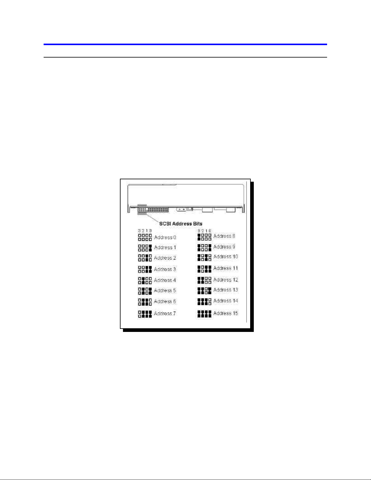
SCSI ID - pins 1 through 8
Assign a unique SCSI ID to your drive and place the jumper(s) accordingly. You can use ID 0
through ID 15; ID 7 is generally reserved for the controller card. The diagram below gives the jumper
positions for each ID.
Auto Start and Auto Start Delay - pins 11 & 12, 21 & 22
The Auto Start and Auto Start Delay pins control when and how the drive can spin up and come
ready. With Auto Start enabled, the motor spins up after power is applied without the need for a
SCSI Start Unit command. With Auto Start disabled, a SCSI Start Unit command is required to make
the drive spin and be ready for media access operations. With Auto Start Delay mode enabled, drive
spin up is delayed by a period of time determined by the Auto Start jumper multiplied by the drive's
SCSI address.
External Activity (LED) - pins 17 & 18
The LED pins can be used to drive an external Light Emitting Diode. Up to 33mA (5%) of TTL level
LED drive current is provided. The LED
Anode may be tied to the +5V source provided on pin 18 of
the front option jumper block, pin 11 of the Auxiliary connector on the 68 pin unitized connector, or
IBM Hard Disk Drive Technical Support Center version 2.0
34L3743IG10
Page 7
Page 8

IBM storage products
Activity pin to complete the circuit. Note: The Ultrastar has two sets of pins, one on the front and one
on the back, which are connected to the same LED driver circuit. The combined current capability is
stated above.
Write Protect - pins 19 & 20
When the Write Protect pin is jumpered, SCSI commands that alter the customer data area portion of
the media will not be performed. The state of this pin is monitored on a per command basis.
Disable Target Initiated Synchronous Negotiation - pins 25 & 26
When the Disable Target Initiated Synchronous Negotiation pin is jumpered, an Initiator is required to
start a negotiation handshake if Synchronous and/or Wide (double byte) SCSI transfers are desired.
Disable SCSI Parity - pins 27 & 28
Jumpering these pins disables SCSI Parity Checking.
Disable Unit Attention - pins 29 & 30
Jumpering these pins disables the drive from building Unit Attention Sense information for commands
immediately following a Power On Reset (POR) or SCSI Bus Reset. Any pending Unit Attention
conditions will also be cleared at POR or SCSI Reset times.
Disable Wide Negotiations - pins 31 & 32
Jumpering these pins causes the drive to operate in a single byte mode. The drive will not negotiate
for wide (double byte) operation.
Force Single-Ended Mode - pins 23 & 24
Jumpering these pins on LVD models causes all models to operate in Single-Ended mode only.
80 pin models - option jumper block
External Activity LED
Auto Start Disable
SCSI Address
Blank
3 2 1 0
| | | |
1 3 5 7
2 4 6 8 10 12 14 16 18 20 22 24 26 28 30 32
Ground
Reserved
Ground
11 13 15 17 19 21 23 25 27 29 31
Reserved
Write Protect
+5V
Auto Start Delay
Force Single-ended Mode
Disable Sync Negotiations
Disable SCSI Parity
Disable Unit Attention
Disable Wide Negotiations
Ground
80 pin SCA-2 front option jumper block
IBM Hard Disk Drive Technical Support Center version 2.0
34L3743IG10
Page 8
Page 9

IBM storage products
68 pin models - option jumper block
Write Protect
+5V
Auto Start Delay
Force Single Ended Mode
Disable Sync Negotiations
Disable SCSI Parity
Disable Unit Attention
Disable Wide Negotiations
Ground Termination
Power Enable
SCSI Address Bits
External Activity LED
Reserved
Ground
Ground
Blank
11 13 15 17 19 21 23 25 27 29 31
Reserved
Auto Start Enable
3 2 1 0
| | | |
1 3 5 7
2 4 6 8 10 12 14 16 18 20 22 24 26 28 30 32
Pin 23 is Reserved on Single Ended model.
Pin 14 is Enable Active Termination on Single Ended model.
68 pin model - auxiliary option jumper block
The 68 pin models contain an auxiliary connector that duplicates some of the functions of the front option
jumper block. The auxiliary connector conforms to SFF 8009 Rev 3.0 and is typically used with a unitized
connector found on external drive enclosures.
: : : : : :
SCSI Address
ID2
+5V ID3
11 9 7 5 3 1
12 10 8 6 4 2
Write Protect
External Activity LED
Ground
ID0
ID1
Unused
Slave Sync
Auto Spin Start
Page 9
IBM Hard Disk Drive Technical Support Center version 2.0
34L3743IG10
Page 10

IBM storage products
Step 4: Mounting the drive
Ÿ After setting the jumpers, mount the hard drive in your system. The Ultrastar drive can be mounted
with any of its six surfaces facing down. See the diagrams below for mounting hole locations.
(6X) 6-32UNC- 2B X 3.8mm MAX
0.25
+
(6X) 6.35
60 + 0.2
41.28+/- 0.5
101.6 + 0.2
44.45+/- 0.25
Mounting hole locations
28.5 + 0.5
You must ensure that the drive has sufficient air flow. Mount the drive in the system using four 6-32 UNC
screws. The maximum screw length is 3.5 mm for the side holes and 6 mm for the bottom holes. Mount
the drive securely enough to prevent excessive motion or vibration.
If you are mounting your drive in a 5.25 inch bay, you may need to purchase mounting brackets from
your computer manufacturer to mount the drive securely.
IBM Hard Disk Drive Technical Support Center version 2.0
34L3743IG10
Page 10
Page 11

IBM storage products
Step 5: Attaching the cables
Ÿ Drives with 68 pin connectors
After the drive has been carefully mounted, connect the SCSI cable and the power cable to the drive. The
SCSI connector and power connector are keyed for proper insertion.
Ÿ Drives with 80 pin connectors
80 pin drives are plugged into backplanes of servers and require no cables. If you want to connect an 80
pin drive to a 68 pin SCSI cable, a converter is needed. Not all SCA converters support LVD mode.
Step 6: Completing physical installation
Ÿ The SCSI bus must be terminated at both ends of the bus since Ultra2 SCSI (LVD) models do not
have onboard active termination. You must supply an external Ultra2 compatible terminator.
• Verify that the cable is properly connected to the SCSI controller.
• Replace the cover on the computer.
• Connect all cables.
• Plug the power cord into the wall.
IBM Hard Disk Drive Technical Support Center version 2.0
34L3743IG10
Page 11
Page 12

IBM storage products
Fixed Disk 3
: None
Serial Port(s)
: 3F8h,2E8h
Step 7: Verifying host adapter settings
Note: The example below uses the Adaptec 2940U2W controller and the Model DMVS-18D drive.
Ÿ Insert a bootable diskette into the diskette drive.
Ÿ Turn the computer on. You should see the drive model displayed when the system is booting.
Ÿ Verify the adapter settings.
Adaptec AHA-2940 Ultra/Ultra W BIOS v1.23
(c) 1996 Adaptec, Inc. All Rights Reserved.
Press <Ctrl><A> for SCSISelect (TM) Utility!
SCSI ID:LUN NUMBER # : # 0:0 - IBM OEM DMVS-18D - Drive C: (80h)
CPU/CLK : Pentium/133MHz Base Memory : 640 KB
Math Coprocessor : Installed Extended Memory : 15360 KB
Fixed Disk 0 : None Shadow RAM : 384 KB
Fixed Disk 1 : None Internal Cache : 16 KB, Enabled
Fixed Disk 2 : None External Cache : 256 KB, Enabled
Ÿ Press [CTRL] [A] to enter the Adaptec SCSI setup utility. The following screen appears.
Adaptec AHA-2940 Ultra/Ultra W SCSISelect (TM) Utility v1.23
AHA-2940 Ultra/Ultra W at Bus:Device 00:0Fh
Would you like to configure the host adapter, or run the SCSI disk utilities:
Select the option and press <Enter>. Press <F5> to switch between color and
monochrome modes.
Configure/View Host Adapter Settings
SCSI Disk Utilities
Options
IBM Hard Disk Drive Technical Support Center version 2.0
Page 12
34L3743IG10
Page 13

IBM storage products
Ÿ SelectConfigure/View Host Adapter Settings. The following screen appears.
Adaptec AHA-2940 Ultra/Ultra W SCSISelect (TM) Utility v1.23
AHA-2940 Ultra/Ultra W at Bus:Device 00:0Fh
Configuration
SCSI Bus Interface Definitions
Host Adapter SCSI ID..................................................................................... 7
SCSI Parity Checking..................................................................................... Enabled
Host Adapter SCSI Termination...................................................................... Automatic
Additional Options
Boot Device Options....................................................................................... Press <Enter>
SCSI Device Configuration............................................................................. Press <Enter>
Advanced Configuration Options.................................................................... Press <Enter>
Ÿ Select Boot Device Options. The screen below appears.
Adaptec AHA-2940 Ultra/Ultra W SCSISelect (TM) Utility v1.23
AHA-2940 Ultra/Ultra W at Bus:Device 00:0Fh
Configuration
Run SCSI Disk Utilities to get devices
in your system.
Boot Target ID...............................................................................................................................................0
Option Listed Below Have NO EFFECT if Multiple Lun Support is Disabled
Boot Lun Number..........................................................................................................................................0
Ÿ Verify or set Boot Target ID.
Ÿ Press ESC to return to the previous screen.
Boot Device
Configuration
IBM Hard Disk Drive Technical Support Center version 2.0
Page 13
34L3743IG10
Page 14

Adaptec AHA-2940 Ultra/Ultra W SCSISelect (TM) Utility v1.23
IBM storage products
Ÿ Select SCSI Device Configuration. The following screen appears.
Ÿ Verify that the Maximum Sync Transfer Rate is the highest possible and that configurations
settings are enabled (set to yes).
Adaptec AHA-2940 Ultra/Ultra W SCSISelect (TM) Utility v1.23
SCSI Device Configuration
SCSI Device ID #0 #1 #2 #3 #4 #5 #6 #7
Initiate Sync Negotiation.................... yes yes yes yes yes yes yes yes
Maximum Sync Transfer Rate........... 40.0 40.0 40.0 40.0 40.0 40.0 40.0 40.0
Enable Disconnection........................ yes yes yes yes yes yes yes yes
Initiate Wide Negotiation................... yes yes yes yes yes yes yes yes
Options Listed Below Have NO EFFECT if the BIOS is Disabled
Send Start Unit Command................ yes yes yes yes yes yes yes yes
SCSI Device ID #8 #9 #10 #11 #12 #13 #14 #15
Initiate Sync Negotiation................... yes yes yes yes yes yes yes yes
Maximum Sync Transfer Rate.......... 40.0 40.0 40.0 40.0 40.0 40.0 40.0 40.0
Enable Disconnection....................... yes yes yes yes yes yes yes yes
Initiate Wide Negotiation.................. yes yes yes yes yes yes yes yes
Options Listed Below Have NO EFFECT if the BIOS is Disabled
Send Start Unit Command............... yes yes yes yes yes ye yes yes
Ÿ Press ESC to return to previous screen.
Ÿ Select Advanced Configuration Options. The screen below appears.
AHA-2940 Ultra/Ultra W at Bus:Device 00:0Fh
Configuration
Plug and Play Scam Support............................................................................................................................................Enabled
Options Listed Below Have NO EFFECT if the BIOS is Disabled
Host Adapter BIOS (Configuration Utility Reserves BIOS Space)..................................................................................Enabled
Support Removable Disks Under BIOS as Fixed Disks..................................................................................................Boot Only
Extended BIOS Translation for DOS Drives > 1 GByte...................................................................................................Enabled
Display <Ctrl-A> Message During BIOS Initialization......................................................................................................Disabled
BIOS Support for Bootable CD-ROM................................................................................................................................Enabled
BIOS Support for Int13 Extensions...................................................................................................................................Enabled
Support for Ultra SCSI Speed...........................................................................................................................................Enabled
Advanced Configuration Options
Ÿ Verify that Extended BIOS Translation for DOS Drives > 1 GByte and BIOS Support for int13
Extensions is enabled.
Ÿ Press ESC to return to the previous screen.
Ÿ Exit from Adaptec settings and save any changes.
IBM Hard Disk Drive Technical Support Center version 2.0
34L3743IG10
Page 14
Page 15

IBM storage products
Step 8: Partitioning the drive
Note: This example uses FDISK to partition your drive. You may use a diferent partitioning program
available on your operating system.
Ÿ Boot to a bootable diskette and type FDISK at the A:\ prompt. If Windows® 95 SR2 or Windows® 98
is used, the following screen will be displayed.
Your computer has a disk larger than 512 MB. This version of Windows
includes improved support for large disks, resulting in more efficient use of
disk space on large drives, and allowing disks over 2 GB to be formatted as
a single drive.
IMPORTANT: If you enable large disk support and create any new drives on
this disk, you will not be able to access the new drive(s) using other operating
systems, including some versions of Windows 95 and Windows NT, as well as
earlier versions of Windows and MS-DOS. In addition, disk utilities that were
not designed explicitly for the FAT32 file system will not be able to work with
this disk. If you need to access this disk with other
operating systems or older disk utilities, do not enable large drive support.
Do you wish to enable large disk support (Y/N)...............? [N]
Ÿ Type Y to select the FAT 32 file system. Type N to select the FAT 16 file system. Note: Select
FAT 32 or FAT 16 if you are using Windows 95 SR2 or Windows 98. FAT 32 partitions utilize disk
space more efficiently and may be greater than 2GB in size. If you are using DOS, Windows 3.1x, or
an earlier version of Windows 95, select FAT 16. The following screen is displayed. [If you have
more than one drive, a fifth option will appear which allows you to select the drive to be partitioned.]
PC DOS Version 7.0
Fixed Disk Setup Program
Copyright IBM Corporation 1983-1994
FDISK Options
Current fixed disk drive: 1
Choose one of the following:
1. Create DOS partition or Logical DOS Drive
2. Set active partition
3. Delete partition or Logical DOS Drive
4. Display partition information
5. Change current fixed disk drive
Enter choice:[1]
Press ESC to exit FDISK
IBM Hard Disk Drive Technical Support Center version 2.0
34L3743IG10
Page 15
Page 16

Restart the system for the partitions to be recognized.
IBM storage products
Ÿ Select option 1 to create a DOS partition. The screen below is displayed.
Create DOS Partition or Logical DOS Drive
Choose one of the following:
1. Create Primary DOS Partition
2. Create Extended DOS Partition
3. Create Logical DOS Drive(s) in the Extended DOS partition.
Enter choice: [3]
Press ESC to return to FDISK Options
• Select option 1 to Create a Primary DOS Partition.
• You will be asked if you want the full capacity of the drive and if you want to make the partition active.
If yes, exit from FDISK. Restart the system and procede to the next step.
• If no, enter the logical drive size in MBs or percent of disk space. Return to the main menu.
• Select option 2 to make the partition active.
• Press ESC to return to the FDISK options.
• Create an Extended DOS Partition by selecting option 1 from the main menu and option 2 from the
second menu. [Both menus are shown above.]
Note: The Maximum Capacity may be smaller than the stated capacity of the drive. This is because
the BIOS of some systems recognizes a Megabyte as 1,048,576 bytes (binary). Drive manufacturers
recognize a Megabyte as 1,000,000 bytes (decimal). The capacities are the same in actual number of
bytes.
Ÿ After creating the Extended DOS Partition, press ESC to return to the FDISK main menu.
Ÿ Select option 1 from the main menu,
Ÿ Then select option 3 to create a Logical DOS Drive in an Extended Partition. The following screen
appears.
Create Logical DOS Drive(s) in the Extended
DOS Partition
No logical drives defined
Total Extended DOS Partition size is 1047 Mbytes
(1 MByte = 1048576 bytes)
Maximum space available for logical drive is 1047Mbytes (100%)
Enter logical drive size in Mbytes or percent of disk space (%).....[1047]
Press ESC to return to FDISK Options
Ÿ Press ESC to return to FDISK and press ESC again to FDISK.
Ÿ
IBM Hard Disk Drive Technical Support Center version 2.0
34L3743IG10
Page 16
Page 17

IBM storage products
Step 9: Formatting the drive
The drive must be formatted before an operating system can be loaded. Format the Primary partition
and any Extended partitions that have been made by following the steps below: .
• After booting from a bootable diskette, run FDISK, option 4 to verify the partition information from the
previous step. Note the drive letters to ensure proper formatting.
• Press ESC to return to the main menu and ESC again to exit FDISK. At the A:\ prompt type format
x: /s (where x is the drive letter). The /s option makes your hard drive bootable by copying the
system files to the hard drive. If you do not want this drive to be bootable, do not use the /s switch.
The following warning is displayed:
WARNING: ALL DATA ON NON-REMOVABLE DISK
DRIVE C: WILL BE LOST!
Proceed with Format (Y/N)?
• Type Y for yes. The time needed to format the drive depends upon the size of the drive.
• When the formatting is complete, format the next logical drive by typing
format x: (where x is the logical drive letter)
• Repeat the above step for each logical drive to be formatted.
Step 10: Installing an operating system
Ÿ After the drive has been formatted, install an operating system. Follow your operating system
installation instructions.
Note: Some controllers, systems, or operating systems may recognize only ANSI SCSI-2 devices. The
Ultrastar reports itself as a SCSI-3 device. Contact the IBM Hard Disk Drive Technical Support Center
for a fix if you encounter this issue.
IBM Hard Disk Drive Technical Support Center version 2.0
34L3743IG10
Page 17
Page 18

IBM storage products
APPENDIX
Making a bootable diskette
If you do not have a bootable diskette, you may want to make one. This may be necessary for installing
your new hard disk drive and in case of system failure.
If you have a bootable Windows operating system, follow the steps below to create a Windows 95 or 98
startup diskette:
Ÿ Insert a blank floppy disk into drive A.
Ÿ From Windows 95 or 98, double click My Computer.
Ÿ Double click Control Panel.
Ÿ Double click Add/Remove Programs.
Ÿ Select Startup Disk tab.
Ÿ Click Create Disk. Follow the prompts.
If you have a bootable DOS operating system, follow the steps below to create a DOS startup diskette:
• Insert a blank floppy disk into drive A.
• At the C:\ prompt, type FORMAT A:/S and press ENTER.
• Follow the instructions displayed.
Controller information
The examples in this guide use an Adaptec controller. If you have a chipset embedded into your motherboard, plug the cable into the port on the motherboard instead of the controller.
If you are purchasing an add-on controller card, you will need to install the controller in one of the empty
slots in your computer. Remove the screw holding the metal plate in place and insert the controller into
the appropriate PCI, EISA or ISA slot on the motherboard, making sure the metal plate from the controller fits into the grooves on the computer frame. Replace the screw and connect the SCSI cables to
the controller and then the hard drive. If you have any questions, refer to the installation manual
enclosed with your controller.
IBM Hard Disk Drive Technical Support Center version 2.0
34L3743IG10
Page 18
Page 19

IBM storage products
Adaptec 3950U2BAdaptec 7880
Windows NT 4.0
Compatibility
The IBM SIT Lab tests Ultrastar drives for compatibility with a wide variety of systems, controller cards,
and operating systems. Testing was done to demonstrate compatibility with the following hardware and
software. Other combinations of hardware and software may function with this drive, but were not tested.
Systems
Acer AP53A
Apple Performa 6400/180
AS400 9406 520
Compaq Deskpro 6000
Compaq Deskpro 2000
Compaq Professional Workstation
6000
Compaq Proliant 1500
Data General
Dell Dimension XPS D300
Dell OptiPlex Gxa 266MTbr
Dell Power Edge 4100
Digital Alpha Server 800 5/333
Digital Alpha Server 4100
Digital VAX 4000
EMC
Gateway 2000 P6-200
Gateway G6-200
HP Netserver LXPro
HP Kayak GM
HP 9000/712
IBM RS6000 E20
IBM RS6000 F50
IBM Intellistation Z-Pro
Micron ClientPro XLU
Micron Millenia MME
Micron Powerdign XSU
NEC Direction SPL 266
NEC Power mate Enterprise
SNI Primergy 460
SGI Octane
SGI Onyx2
SGI 02
Sun Sparc Station 20
Tyan P5-166 Motherboard
SCSI Controllers
Adaptec AAA-131
Adaptec AAA-133
Adaptec AIC-7880
Adaptec ARO
Adaptec 2940UW
Adaptec 2940U2W
Adaptec Power Domain 2940U2W
Adaptec 3940W
Adaptec AHA-7890
Adaptec AIC-7880
Adaptec Power Domain
AHA-3940UW v3
AMI MegaRaid 428
AMI MegaRaid 438
Buslogic BT-956
Compaq Wide-Ultra SCSI-2
Compaq Wide-Ultra SCSI-3
DG Proprietary
Diamond Fireport 40
DPT 2144UW
DPT 3334UW
EMC 80 Pin Ultra
IBM ServeRAID
IBM ServeRAID II
Mylex AcceleRAID 250
Mylex DAC 960
Mylex DAC1164P
Qlogic QLA1040B
Symbios Logic SYM8951U
SCSI Operating systems
AIX 4.3.2
DEC VMS 6.2
DEC VMS 7.1
HP-UX 10.10
Irix 6.3
Irix 6.4
Irix 64 Rel 6.5
MacOS 7.5.3
MacOS 7.6
MacOS 8.5
MS DOS 6.20
Novell Netware 4.11
OS2/Warp V.4.20
RedHat Linux 5.2
SCO Unix 3.2.4.2
SCO OpenServer 5.0.2
SCO Unixware 2.1.1
SCO Unixware 2.1.2
Sun OS 5.5.1
Sun Solaris 2.6
Windows 95
Windows 95 OSR2
Windows 98
BIOSs
AlphaBios 5.64 971212.1414
AMI 1.00.02.DT05
AMI 1.00.11.CD0L
AMI 1.00.13.CD0
AMI 1.00.04.CS1T
AMI 1.00.08CSIT
AMI Ver 2 24/8/95
Award 4.51PG
Compaq 686V 9/28/97
Compaq 586M 11/18/97
Compaq Professional Workstation
6000 BIOS 5/5/97
Compaq E12 4/5/96
Galaxy
IBM Sure Path 1/24/97
Phoenix 1.10 A04
Phoenix 4.0, Release 5.12
Phoenix 4.0, Release 6
Pheonix 4.04
Phoenix 4.05 1.01.92
Phoenix 4.05 A03
Phoenix 4.05 A06
SGI 6.4 2/5/97
IBM Hard Disk Drive Technical Support Center version 2.0
34L3743IG10
Page 19
Page 20

IBM storage products
Technical support
Contact technical support via
Web www.ibm.com/harddrive
Voice 888.426.5214 or 507.286.5825
Fax 507.253.4111
e-mail drive@us.ibm.com
Support is also available in Singapore at:
Voice 1800.418.9595 or 65.6.418.9595
e-mail drive@sg.ibm.com
When calling the Technical Support Center be prepared to give the technical support representative the
drive part number, its serial number, and the system information.
Automated Fax Back Service
U.S.A. 408.256.5218
Singapore 800.418.9696
England 0800.96.6948
Germany 0130.82.6089
France 0800.902229
Italy 167.875148
IBM Hard Disk Drive Technical Support Center version 2.0
34L3743IG10
Page 20
Page 21

IBM storage products
Glossary
ANSI (American National Standards Institute)
ANSI is the lead organization for encouraging and developing technological standards. ANSI represents
the United States in the IEC (International Electrotechnical Commission) and the ISO (International
Standards Organization).
Backup
Storing information from a hard drive to another storage area in order to prevent data loss.
BIOS (Basic Input/Output System)
The BIOS is the first level of software contained in a computer. It provides basic, low level control for keyboards, video, hard disk drives, and floppy drives. It also provides the initial intelligence that allows the
computer system to find an operating system to run.
Boot/Boot-up
To prepare a computer for operation by loading an operating system.
Capacity
The amount of information, expressed in bytes, that can be stored on a hard drive. Also known as
storage capacity.
Compatibility
The capability of a hardware or software component to conform with the interface requirements of a given
data processing system without adversely affecting its functions.
Disk drive
The primary data storage device used by computers. Disk drives are used to record, store and retrieve
digital information.
Electrostatic discharge
The rapid change in electrical energy caused by static electricity. This can damage or destroy electronic
equipment or hardware. Electrostatic discharge can be prevented by grounding oneself before handling
any electronic equipment.
FAT16 & FAT32 (File Allocation Table)
The file allocation table is a group of sectors in a hard drive that contains address chains for the different
files on a hard disk drive. There are usually two FATs (kept in different locations) on a hard drive.
FAT32 is available in the Windows® 95 & Windows® 98 operating systems. FAT32 receives its
designation because it allows 32 bits of addressing as opposed to 16 bits in the FAT16 file system.
FDISK
FDISK is a program run in DOS that allows a user to partition a hard disk drive. Partitioning your hard
disk drive is essential for it to work properly.
Format
To prepare a hard drive so that it can store data. In the DOS formatting process, the computer verifies
the clusters within a partition.
Hard disk drive (HDD)
A stand alone disk drive that reads and writes data onto rigid disks and can be attached to a port on the
system unit. Synonymous with fixed disk drive and hard drive.
Interface
A hardware or software protocol, contained in the electronics of the disk controller and drive, that manages the exchange of data between the hard disk drive and the computer. The most common interfaces
for small computer systems are ATA (IDE) and SCSI.
IBM Hard Disk Drive Technical Support Center version 2.0
34L3743IG10
Page 21
Page 22

IBM storage products
Jumpers
A small piece of metal covered with plastic that enables a particular function in a hard drive when it connects two pins on a jumper block.
Jumper settings
Different modes which are achieved by placing the jumper on particular pins on a device. These modes
determine the behavior of the device. Settings are changeable by the user, but remain constant during
operation. See Jumpers.
LVD (Low Voltage Differential)
A highly compatible computer disk drive interface that is faster and more reliable than SCSI. Also known
as Ultra2SCSI.
Motherboard
Holds the computer's main processors and circuitry, and also contains thememory, BIOS, interconnection
circuitry and expansion slots.
Multimode
A drive that can operate on an LVD bus or a Single-ended bus.
Operating system
Software that controls the execution of programs and may provide functions such as resource allocation,
scheduling, input/output control, and data management. Although operating systems are predominantly
software, partial hardware implementations are possible.
Partition
A portion of a hard drive dedicated to a particular operating system or application and accessed as a
single logical volume.
SCSI (Small Computer System Interface)
An intelligent parallel peripheral interface characterized by its use of high level communication between
devices. Pronounced “scuzzy”.
Termination
The signals on a SCSI bus must be terminated at both ends of the bus. This is generally done by the
controller automatically and requires an “external” terminator on the last connector of the bus.
IBM Hard Disk Drive Technical Support Center version 2.0
34L3743IG10
Page 22
Page 23

IBM storage products
®
© International Business Machines Corporation 2000
www.ibm.com/harddrive
IBM Hard Disk Drive Technical Support Center
Dept. WCN
3605 Highway 52 North
Rochester, MN 55901
Telephone: 888.IBM.5214 or 507.286.5825
Fax: 507.253.DRIVE
E-mail: drive@us.ibm.com
Singapore Technical Support Center
Telephone: 1800.418.9595 or 65.6.418.9595
E-mail: drive@sg.ibm.com
IBM Storage Systems Division
5600 Cottle Road
San Jose, CA 95193
www.ibm.com/storage
Printed in the United States of America
01-00
All Rights Reserved
IBM is the registered trademark and Deskstar is a trademark of
International Business Machines Corporation. Microsoft, Windows, and
Windows NT are registered trademarks of Microsoft Corporation.
Other company, product, and service names may be trademarks or
service marks of others.
Produced by the IBM Hard Disk Drive Technical Support Center.
This information is believed to be accurate, but is supplied without
guarantee. Document subject to change without notice.
Date: 04 January, 2000
IBM Hard Disk Drive Technical Support Center version 2.0
34L3743IG10
Page 23
 Loading...