


Hyundai N700E 004 LF, N700E 007 SF, N700E 004 SF, N700E 007 LF, N700E 022 LF Instruction Manual
...
N700E INSTRUCTION MANUAL
N700E INSTRUCTION MANUALN700E INSTRUCTION MANUAL
N700E INSTRUCTION MANUAL
N700E
INSTRUCTION MANUAL
A


N700E INSTRUCTION MANUAL
N700E INSTRUCTION MANUALN700E INSTRUCTION MANUAL
N700E INSTRUCTION MANUAL
1. Installation
!
CAUTION
Be sure to install the unit on flame resistant material such as metal.
Otherwise, there is a danger of fire.
Be sure not to place anything highly flammable in the vicinity.
Otherwise, there is a danger of fire.
Do not carry unit by top cover, always carry by supporting base of unit.
There is a risk of falling and injury.
Be sure not to let foreign matter enter inverter such as cut wire refuse, spatter from welding,
iron refuse, wire, dust, etc.
Otherwise, there is a danger of fire.
Be sure to install inverter in a place which can bear the weight according to the specifications
in the text. (Chapter 2. Installation)
Otherwise, it may fall and there is a danger of injury.
Be sure not to install and operate an inverter which is damaged or has parts which are
missing.
Otherwise, there is a danger of injury.
Be sure to install the inverter in an area which is not exposed to direct sunlight and is well
ventilated. Avoid environments which tend to be high in temperature, high in humidity or to
have dew condensation, as well as places with dust, corrosive gas, explosive gas, highly
flammable gas, grinding-fluid mist, salt damage, etc.
Otherwise, there is a danger of fire.
I
General Safety Information
General Safety InformationGeneral Safety Information
General Safety Information
N700E INSTRUCTION MANUAL
N700E INSTRUCTION MANUALN700E INSTRUCTION MANUAL
N700E INSTRUCTION MANUAL
2. Wiring
!
WARNING
Be sure to ground the unit.
Otherwise, there is a danger of electric shock and/or fire.
Wiring work should be carried out by qualified electricians.
Otherwise, there is a danger of electric shock and/or fire.
Implement wiring after checking that the power supply is off.
Otherwise, there is a danger of electric shock and/of fire.
After installing the main body, carry out wiring.
Otherwise, there is a danger of electric shock and/or injury.
!
CAUTION
Make sure that the input voltage is:
Three phase 200 to 240V 50/60Hz
Three phase 380 to 480V 50/60Hz
Be sure not to single phase the input.
Otherwise, there is a danger of fire.
Be sure not to connect AC power supply to the output terminals(U, V, W).
Otherwise, there is a danger of injury and/or fire and/or damage to unit.
Be sure not to connect a resistor to the DC terminals(P, RB) directly.
Otherwise, there is a danger of fire and/or damage to unit.
Be sure to install an earth leakage breaker or the fuse(s) which is(are) the same phase as the
main power supply in the operation circuit.
Otherwise, there is a danger of fire and/or damage to unit.
As for motor leads, earth leakage breakers, and electromagnetic contactors, be sure to use
equivalent ones with the specified capacity(rated).
Otherwise, there is a danger of fire and/or damage to unit.
Do not stop operation by switching off the electromagnetic contactors on the primary or
secondary sides of the inverter.
Otherwise, there is a danger of injury and/or machine breakage.
Fasten the screws to the specified torque. Check so that there is no loosening of screws.
Otherwise, there is a danger of fire and/or injury to personnel.
II
General Safety Information
General Safety InformationGeneral Safety Information
General Safety Information
N700E INSTRUCTION MANUAL
N700E INSTRUCTION MANUALN700E INSTRUCTION MANUAL
N700E INSTRUCTION MANUAL
3. Control and operation
!
WARNING
Be sure to turn on the power supply with the front case is closed.
While the inverter is energized, be sure not to open the front case.
Otherwise, there is a danger of electric shock.
Be sure not to operate the switches with wet hands.
Otherwise, there is a danger of electric shock.
While the inverter is energized, be sure not to touch the inverter terminals even while the unit
is not running.
Otherwise, there is a danger of electric shock.
If the retry mode is selected, it may suddenly restart during the trip stop.
Be sure not to approach the equipment. (Be sure to design the equipment so that personnel
safety will be secured even if equipment restarts.)
Otherwise, there is a danger of injury.
Even if the power supply is cut for a short period of time, the inverter may restart operation
after the power supply is restored if the operation command is given.
If a restart may incur danger to personnel, be sure to make a circuit so that it will not restart
after power recovery.
Otherwise, there is a danger of injury.
The stop key is valid only when a function is on. Ensure that there is a hard wired emergency
stop that is separate from the stop key of the inverter.
Otherwise, there is a danger of injury.
With the operation command on, if the alarm reset is ordered, the inverter can restart
suddenly. Be sure to set the alarm reset after checking the operation command is off.
Otherwise, there is a danger of injury.
Be sure not to touch the inside of the energized inverter or to put a shorting bar into it.
Otherwise, there is a danger of electric shock and/or fire.
III
General Safety Information
General Safety InformationGeneral Safety Information
General Safety Information
N700E INSTRUCTION MANUAL
N700E INSTRUCTION MANUALN700E INSTRUCTION MANUAL
N700E INSTRUCTION MANUAL
!
CAUTION
The cooling fins will have a high temperature. Be sure not to touch them.
Otherwise, there is a danger of getting burned.
Low to high speed operation of the inverter can be easily set. Be sure to operate it after
checking the tolerance of the motor and machine.
Otherwise, there is a danger of injury.
Install an external breaking system if needed.
Otherwise, there is a danger of injury.
If a motor is operated at a frequency outside of the standard setting value (50Hz/60Hz), be
sure to check the speeds of the motor and the equipment with each manufacturer, and after
getting their consent, operate them.
Otherwise, there is a danger of equipment breakage.
Check the following before and during the test run.
Was the direction of the motor correct?
Did the inverter trip for on acceleration or deceleration?
Were the RPM and frequency motor correct?
Were there any abnormal motor vibrations or noises?
Otherwise, there is a danger of machine breakage.
The AC reactor must be installed When the power is not stable. if not, inverter can be broken.
4. Maintenance, inspection and part replacement
!
WARNING
After turning off the input power supply, do not perform the maintenance and inspection for at
least 10 minutes.
Otherwise, there is a danger of electric shock.
Make sure that only qualified persons will perform maintenance, inspection and/or part
replacement.
(Before starting the work, remove metallic objects(wristwatch, bracelet, etc.) from a worker.
(Be sure to use insulated tools.) Otherwise, there is a danger of electric shock and/or injury.
5. Others
IV
!
WARNING
Never modify the unit.
Otherwise, there is a danger of electric shock and/or injury.
General Safety Information
General Safety InformationGeneral Safety Information
General Safety Information

N700E INSTRUCTION MANUAL
N700E INSTRUCTION MANUALN700E INSTRUCTION MANUAL
N700E INSTRUCTION MANUAL
CONTENTS
1. GENERAL DESCRIPTION ..................................................................................... 1
2. Installation and Wiring ............................................................................................. 1
Operation ................................................................................................................... 16
Parameter Code List .................................................................................................... 1
3. Using intelligent terminals ....................................................................................... 1
4. Protective function ................................................................................................... 1
5. Troubleshooting Tips ................................................................................................ 1
6. Maintenance and Inspection ..................................................................................... 1
7. RS485 Communication (Option) .............................................................................. 1
8. Specification ............................................................................................................. 1
V


N700E INSTRUCTION MANUAL
N700E INSTRUCTION MANUALN700E INSTRUCTION MANUAL
N700E INSTRUCTION MANUAL
1. GENERAL DESCRIPTION
1.1 Inspection upon Unpacking
1.1.1 Inspection of the unit
Please open the package, remove the inverter, please check the following items.
If you discover any unknown parts or the unit is damaged, please contact HYUNDAI.
(1) Make sure that the package contains one operation manual for the inverter.
(2) Make sure that there was no damage (broken parts in the body) during transportation of the unit.
(3) Make sure that the product is the one you ordered by checking the label specification.
Fig1-1 Outlook of N700E Inverter (1frame, 2frame, 3frame)
Fig1-2 Contents of Specification label
1.1.2 Instruction manual
This instruction manual is the manual for the N700E inverters.
Before operation of the inverter, read the manual carefully. After reading this manual, keep it on
1

N700E INSTRUCTION MANUAL
N700E INSTRUCTION MANUALN700E INSTRUCTION MANUAL
N700E INSTRUCTION MANUAL
hand for future reference
1.2 Questions and Warranty of the Unit
1.2.1 Questions on Unit
• If you have any questions regarding damage to the unit, unknown parts or for general inquiries,
please contact your LOCAL HYUNDAI BRANCH with the following information.
(1) Inverter Model
(2) Production Number (Serial No.)
(3) Date of purchase
(4) Reason for Calling
1 Damaged part and its condition etc.
2 Unknown parts and their contents etc
1.2.2 Warranty for the unit
• The warranty period of the unit is one year after the purchase date. However the warranty will be void if
the fault is due to;
3 Incorrect use as directed in this manual, or attempted repair by unauthorized personnel.
4 Any damage sustained other than from transportation (Which should be reported
immediately).
5 Using the unit beyond the limits of the specifications.
6 Natural Disasters : Earthquakes, Lightning, etc
• The warranty is for the inverter only, any damage caused to other equipment by malfunction of the inverter
is not covered by the warranty.
• Any examination or repair after the warranty period (one-year) is not covered. And within the warranty
period any repair and examination which results in information showing the fault was caused by any of the
items mentioned above, the repair and examination costs are not covered. If you have any questions
regarding the warranty, please contact either your Local HYUNDAI Branch.
2

N700E INSTRUCTION MANUAL
N700E INSTRUCTION MANUALN700E INSTRUCTION MANUAL
N700E INSTRUCTION MANUAL
1.3 Appearance
Fig1-3 Outlook of N700E Inverter (1frame)
Fig1-4 Outlook of N700E Inverter (2frame)
3
Front Cover
Main circuit terminals
Operator
Control circuit terminals

N700E INSTRUCTION MANUAL
N700E INSTRUCTION MANUALN700E INSTRUCTION MANUAL
N700E INSTRUCTION MANUAL
4

N700E INSTRUCTION MANUAL
N700E INSTRUCTION MANUALN700E INSTRUCTION MANUAL
N700E INSTRUCTION MANUAL
Fig1-5 Outlook of N700E Inverter (3frame)
5


N700E INSTRUCTION MANUAL
N700E INSTRUCTION MANUALN700E INSTRUCTION MANUAL
N700E INSTRUCTION MANUAL
2. Installation and Wiring
2.1 Installation
!
CAUTION
Be sure to install the unit on flame resistant material such as metal.
Otherwise, there is a danger of fire.
Be sure not to place anything flammable in the vicinity.
Otherwise, there is a danger of fire.
Do not carry the unit by the top cover, always carry by supporting the base of unit.
There is a risk of falling and injury.
Be sure not to let foreign matter enter such as cut wire refuse, spatter from
welding, iron refuse, wire, dust, etc.
Otherwise, there is a danger of fire.
Be sure to install the inverter in a place which can bear the weight according to
the specifications in the text.
Otherwise, it may fall and result in possible injury.
Be sure not to install and operate an inverter which is damaged or parts of which
are missing.
Otherwise, there is a danger of injury.
Be sure to install the inverter in an area which is not exposed to direct sunlight
and is well ventilated. Avoid environments which tend to be high in temperature,
high in humidity or to have dew condensation, as well as places with dust,
corrosive gas, explosive gas, inflammable gas, grinding-fluid mist, salt damage,
etc.
Otherwise, there is a danger of fire.
1
N700E INSTRUCTION MANUAL
N700E INSTRUCTION MANUALN700E INSTRUCTION MANUAL
N700E INSTRUCTION MANUAL
2.1.1 Installation
(1) Transportation
This inverter has plastic parts. So handle with care.
Do not over tighten the wall mounting fixings as the mountings may crack, causing is a risk of falling.
Do not install or operate the inverter if there appears to be damaged or parts missing.
(2) Surface for the mounting of inverter
The temperature of the inverter heatsink can rise very high.
The surface, to which the inverter will be mounted, must be made of a non-flammable material(i.e steel)
due to the possible risk of fire. Attention should also be made to the air gap surrounding the inverter.
Especially, when there is a heat source such as a breaking resistor or reactor.
Fig 2- Surface for the mounting of inverter
(3) Operating Environment-Ambient Temperature
The ambient temperature surrounding the inverter should not exceed the allowable temperature range
(-10 to 40℃).
The temperature should be measured in the air gap surrounding the inverter, shown in the diagram
above. If the temperature exceeds the allowable temperature, component life will become shortened
especially in the case of the Capacitors.
(4) Operating Environment-Humidity
The humidity surrounding the inverter should be within the limit of the allowable percentage range (20%
to 90% / RH).
Under no circumstances should the inverter be in an environment where there is the possibility of
moisture entering the inverter.
Also avoid having the inverter mounted in a place that is exposed to the direct sunlight.
(5) Operating Environment-Air
Install the inverter in a place free from dust, corrosive gas, explosive gas, combustible gas, mist of
coolant and sea damage.
(6) Mounting Position
Mount the inverter in a vertical position using screws or bolts. The mounting surface should also be free
from vibration and can easily hold the weight of the inverter.
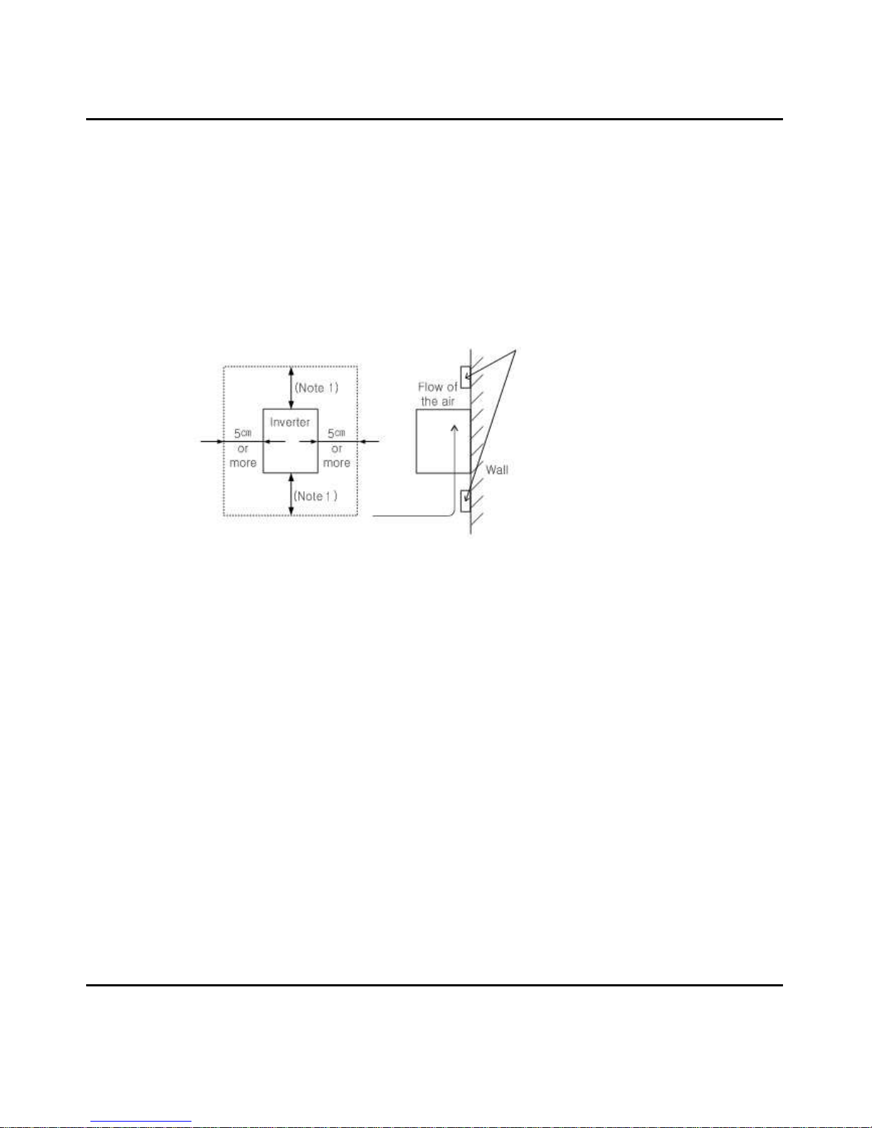
(7) Ventilation within an Enclosure
If you are installing one or more inverters in an enclosure a ventilation fan should be installed. Below is
a guide to the positioning of the fan to take the airflow into consideration. The positioning of inverter,
cooling fans and air intake is very important.
2
Ensure proper spacing for ventilation to
prevent the unit from overheating.
(Note1)
10cm or more

N700E INSTRUCTION MANUAL
N700E INSTRUCTION MANUALN700E INSTRUCTION MANUAL
N700E INSTRUCTION MANUAL
If these positions are wrong, airflow around the inverter decreases and the temperature surrounding
the inverter will rise. So please make sure that the temperature around is within the limit of the
allowable range.
.
3

N700E INSTRUCTION MANUAL
N700E INSTRUCTION MANUALN700E INSTRUCTION MANUAL
N700E INSTRUCTION MANUAL
2.2 Wiring
!
WARNING
Be sure to ground the unit.
Otherwise, there is a danger of electric shock and/or fire.
Wiring work should be carried out by qualified electricians.
Otherwise, there is a danger of electric shock and/or fire.
Implement wiring after checking that the power supply is off.
Otherwise, there is a danger of electric shock and/of fire.
After mounting the inverter, carry out wiring.
Otherwise, there is a danger of electric shock and/or injury.
!
CAUTION
Be sure not to power a three-phase-only inverter with single phase power.
Otherwise, there is a danger of fire.
Be sure not to connect AC power supply to the output terminals(U, V, W).
Otherwise, there is a danger of injury and/or fire and/or damage to unit.
Be sure to set a earth leakage breaker or the fuse(s) which is(are) the same
phase as the main power supply in the operation circuit.
Otherwise, there is a danger of fire and/or damage to unit.
As for motor leads, earth leakage breakers, and electromagnetic contactors, be
sure to use equivalent ones with the specified capacity(rated).
Otherwise, there is a danger of fire and/or damage to unit..
Do not stop operation by switching off the electromagnetic contactors on the
primary or secondary sides of the inverter.
Otherwise, there is a danger of injury and/or machine breakage.
4

N700E INSTRUCTION MANUAL
N700E INSTRUCTION MANUALN700E INSTRUCTION MANUAL
N700E INSTRUCTION MANUAL
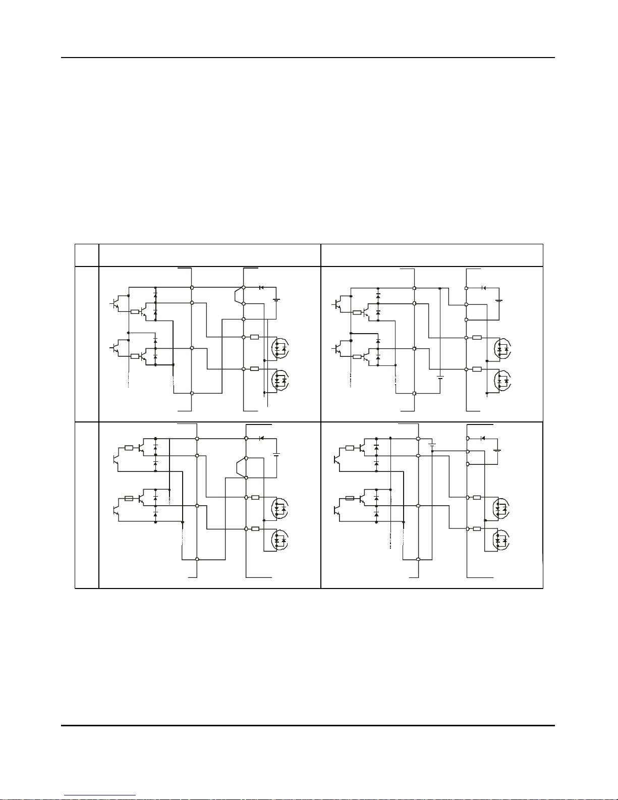
2.2.1 Terminal Connection Diagram (sink type)
5

N700E INSTRUCTION MANUAL
N700E INSTRUCTION MANUALN700E INSTRUCTION MANUAL
N700E INSTRUCTION MANUAL
Fig.2-3 Terminal Connection Diagram (sink type)
6

N700E INSTRUCTION MANUAL
N700E INSTRUCTION MANUALN700E INSTRUCTION MANUAL
N700E INSTRUCTION MANUAL
(1) Explanation of main circuit Terminals
Symbol Terminal Name Explanation of contents
R,S,T (R,S)
Main power Connect alternating power supply.
U,V,W
Inverter output Connect three-phase motor.
P, RB
External braking resistor Connect optional External braking resistor.
G
Inverter earth terminals
Grounding terminal.
Table 2-1 Explanation of main circuit terminals
(2) Control circuit Terminals
Signal
Terminal
Symbol
Terminal name Terminal function
Input
signal
P24 Interface power
24VDC ±10%, 35㎃
5 (FRS)
Intelligent Input Terminal
Forward run command(FW), Reverse run command(RV),
multi-speed commands1-4(CF1-4), 2-stage accel/decel (2CH),
Reset(RS), Terminal software lock(SFT),
Unattended start protection(USP)
(Note2)
,
Free run stop(FRS), Jogging operation(JG),
External trip(EXT)
Contact input :
Close : ON (operating)
Open : OFF(stop)
Minimum ON
TIME :12ms or more
4 (CF2)
3 (CF1)
2 (RV)
1 (FW)
CM1 Common terminal for input or monitor signal
Monitor
signal
FM Analog Monitor (Frequency, Current, Voltage)
Analog Frequency
Meter
Frequ
ency
comm
and
signal
H Frequency power 10VDC
O/OI
Frequency command power terminal (voltage)
Frequency command terminal (current)
0-10VDC,
Input Impedance 10kΩ
4-20mA,
Input Impedance 210Ω
L Analog power common
Intelligent
Output
signal
AL0
AL1
AL2
Intelligent output signals :
at normal status, power off : AL0-AL2 (closed)
at abnormal status : AL0-AL1(closed)
AL0 AL1 AL2
Contact rating:
AC 250V 2.5A
(resistor load)
0.2A
(inductor load)
DC 30V 3.0A
(resistor load)
0.7A
(inductor load)
Table2-2 Control circuit Terminals
7

N700E INSTRUCTION MANUAL
N700E INSTRUCTION MANUALN700E INSTRUCTION MANUAL
N700E INSTRUCTION MANUAL
2.2.2 Main circuit wiring
(1) Warning on wiring
When carrying out work on the inverter wiring make sure to wait for at least ten minutes before you
remove the cover. Be sure to verify that the charge lamp is not illuminated.
A final check should always be made with a voltage meter.
After removing the power supply, there is a time delay before the capacitors will dissipate their charge.
1 Main power terminals (R, S and T)
Connect the main power terminals (R, S and T) to the power supply through an electromagnetic
contactor or an earth-leakage breaker.
N700 recommends connecting the electromagnetic contactor to the main power terminals,
because when the protective function of the inverter operates, it isolates the power supply and
prevents the spread of damage and accident.
This unit is for a three-phase power supply. Be sure not to power a three-phase only inverter
with single phase power. Otherwise, there is the possibility of damage to the inverter and the
danger of fire.
If you require a single phase power supply unit, please contact your local HYUNDAI Branch.
The inverter enters into the following condition at the occurrence of open phase if it is selected
open phase protection is valid :
-
R phase, S phase or T phase, open phase condition:
It becomes single-phase operation condition. Trip operation, such as a deficiency voltage or
over current, may occur.
Don't use it under open phase condition. A converter module may be damaged as a result of
the following conditions. Use caution when
-
an unbalance of the power supply voltage is more than 3%
-
Power supply capacity is more than 10 times of the capacity of inverter and case beyond
500kVA.
-
A drastic change in the power supply
(Example) Turning on/off of the power supply should not be done more than three times in one
minute. It has the possibility of damaging the inverter.
2 Inverter output terminals (U, V, and W)
Using a heavier gauge wire can prevent the voltage drop.
Particularly when outputting low frequencies, the torque of the motor will be reduced by the
voltage drop of the wire.
Do not install power factor correction capacitors or a surge absorber to the output.
The inverter will trip or sustain damage to the capacitors or the surge absorber.
In the case of the cable length being more than 65 feet, it is possible that a surge voltage will be
generated and damage to the motor is caused by the floating capacity or the inductance in the
wire. When an EMC filter is to be installed, please contact your local HYUNDAI branch.
In the case of two or more motors, install a thermal relay to each motor.
Make the RC value of the thermal relay the value of 1.1 times of motor rated electric current.
3 External braking resistor connection terminals (P, RB)
The regenerative braking circuit (BRD) is built-in as standard
When braking is required, install an external-braking resistor to these terminals.
The cable length should be less than 16 feet, and twist the two connecting wires to reduce
inductance.
Do not connect any other device other than the external braking resistor to these terminals.
When installing an external braking resistor make sure that the resistance is correctly rated to
limit the current drawn through the BRD.
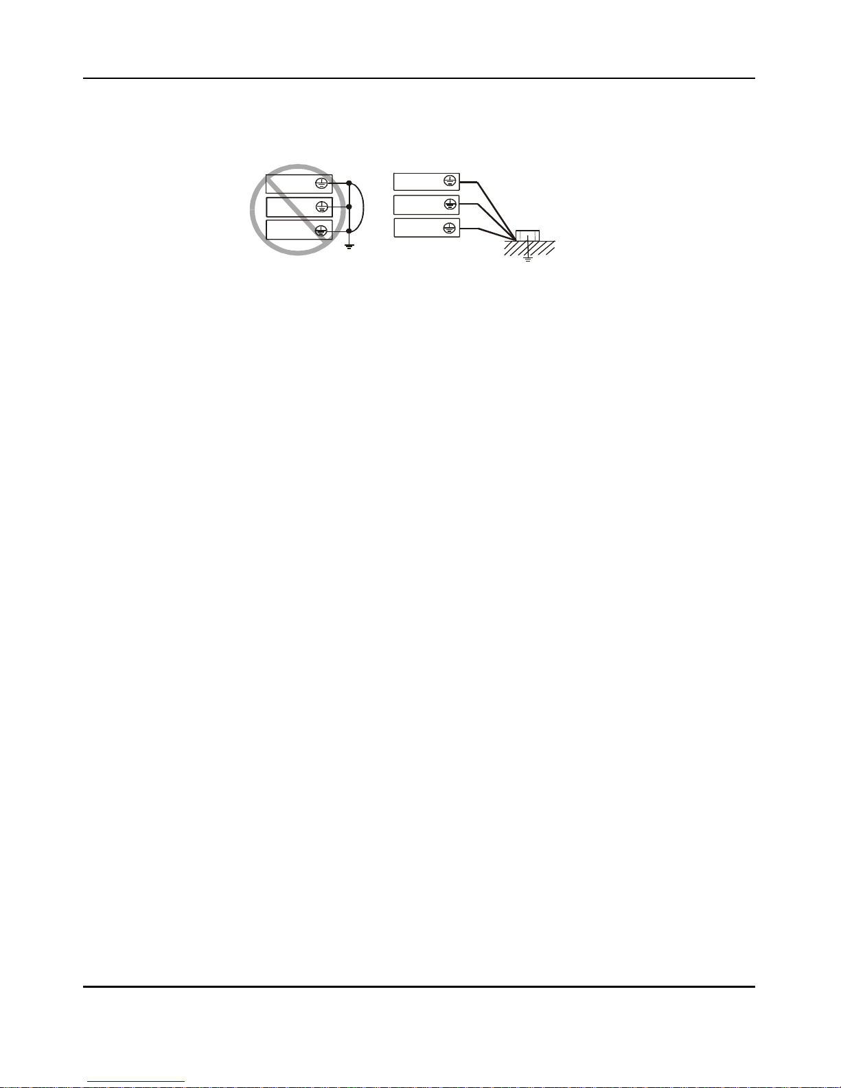
4 Earth Ground (G)
Make sure that you securely ground the inverter and motor for prevention of electric shock.
The inverter and motor must be connected to an appropriate safety earth ground and follow all
8
N700E INSTRUCTION MANUAL
N700E INSTRUCTION MANUALN700E INSTRUCTION MANUAL
N700E INSTRUCTION MANUAL
local electrical codes.
In case connecting 2 or more inverters, use caution not to use a loop which can cause some
malfunction of the inverter.
Fig. 2- 4 Earth Ground (G)
9
INVERTER
INVERTER
INVERTER
INVERTER
INVERTER
INVERTER
N700E INSTRUCTION MANUAL
N700E INSTRUCTION MANUALN700E INSTRUCTION MANUAL
N700E INSTRUCTION MANUAL
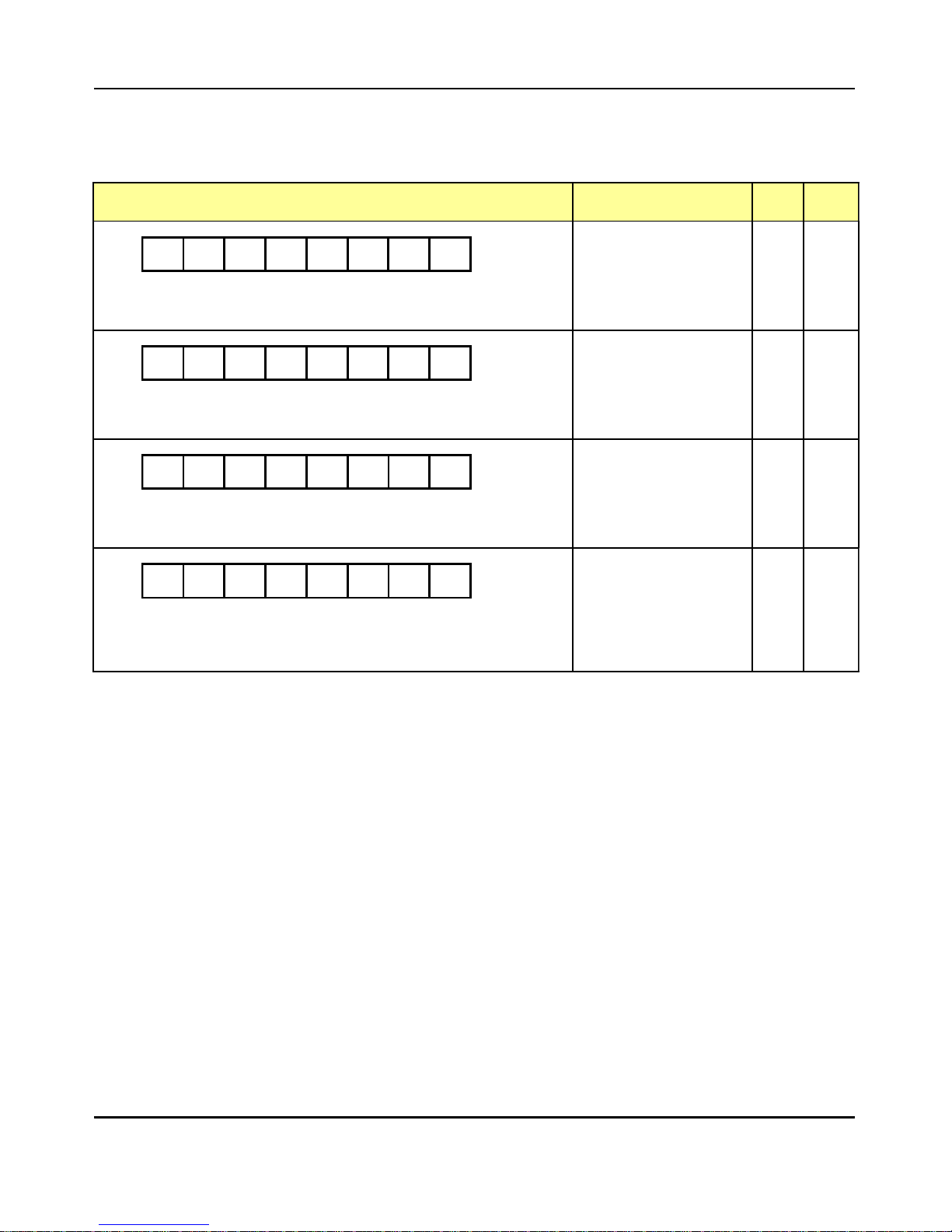
(2) Wiring of main circuit terminals
The wiring of main circuit terminals for the inverter are in the following pictures.
Wiring of terminals Corresponding type
Screw
Size
Width
(㎜)
R S RB P U V W
N700E-004SF
N700E-007SF
M3 7.62
R S T RB P U V W
N700E-004LF
N700E-007LF
N700E-015LF
M3 7.62
R S RB P U V W
N700E-015SF
N700E-022SF
M4 11
R S T RB
P
U V W
N700E-022LF
N700E-037LF
N700E-004HF
N700E-007HF
N700E-015HF
N700E-022HF
N700E-037HF
M4 11
Table 2-3 Wiring of main circuit terminals
10

N700E INSTRUCTION MANUAL
N700E INSTRUCTION MANUALN700E INSTRUCTION MANUAL
N700E INSTRUCTION MANUAL
(3) Applicable Tools
Note1 : The applicable equipment is for HYUNDAI standard four pole
squirrel cage motor.
Note2 : Be sure to consider the capacity of the circuit breaker to be used.
Note3 : Be sure to use larger wire for power lines if the distance exceeds 20m.
Note4 : Be sure to use an grounding wire same size of power line or similar.
Note5 : Use 0.75㎟for AL relay.
Separate by the sum(wiring distance from inverter to power
supply, from inverter to motor for the sensitive current of
leakage breaker (ELB)
Wiring distance Sensitive Current(mA)
100m and less 50
300m and less 100
Table2-4 Sensitive current according to wiring distance
Note6 : When using CV line and wiring by rigid metal conduit, leak flows.
Note7 : IV line is high dielectric constant. SO the current increase 8 times.
Therefore, use the sensitive current 8 times as large as that of the left list.
And if the distance of wire is over 100m, use CV line.
11
Name Function
(1)
Input reactor
(harmonic control,
electrical coordination,
power-factor
improvement)
This part is used when the unbalance voltage rate is 3% or more and
power supply is 500 kVA or more, and there is a rapid change in the
power supply. It also improves the power factor.
(2)
Noise filter for Inverter
This part reduces common noise generated between the power
supply and the ground, as well as normal noise. Put it in the primary
side of inverter.
(3)
Radio noise filter
(zero-phase reactor)
Using the inverter may cause noise on the peripheral radio through
the power lines.
This part reduces noise.
(4)
Input radio noise filter
(capacitor filter)
This part reduces radiation noise emitted from wire at the input.
(5)
Breaking resistor
Regenerative breaking
unit
This part is used for applications that need to increase the brake
torque of the inverter or to frequently turn on and off and to run high
inertia load.
(6)
Output noise filter
This part reduces radiation noise emitted from wire by setting
between inverter and motor. And it reduces wave fault to radio and
TV, it is used for preventing malfunction of sensor and measuring
instruments.
(7)
Radio noise filter
(Zero-phase reactor)
This part reduces noise generated at the output of the inverter.
(It is possible to use for both input and output.)
(8)
Output alternation
reactor
Reducing vibration,
thermal
Relay, preventing
Misapplication
Running motors with the inverter generates vibration greater than that
with commercial power supply. This part installed between the inverter
and motor reduces torque ripple. When the cable length between the
inverter and motor is long (10m or more), a countermeasure for a
malfunction of the thermal relay by harmonic due to switching on
inverter is taken by inserting reactor.
There is the way to use current sensor in stead of thermal relay.
LCR filter Sine-wave filter at the output.

N700E INSTRUCTION MANUAL
N700E INSTRUCTION MANUALN700E INSTRUCTION MANUAL
N700E INSTRUCTION MANUAL
Table 2-5 Optional accessories for improved performance
12
N700E INSTRUCTION MANUAL
N700E INSTRUCTION MANUALN700E INSTRUCTION MANUAL
N700E INSTRUCTION MANUAL
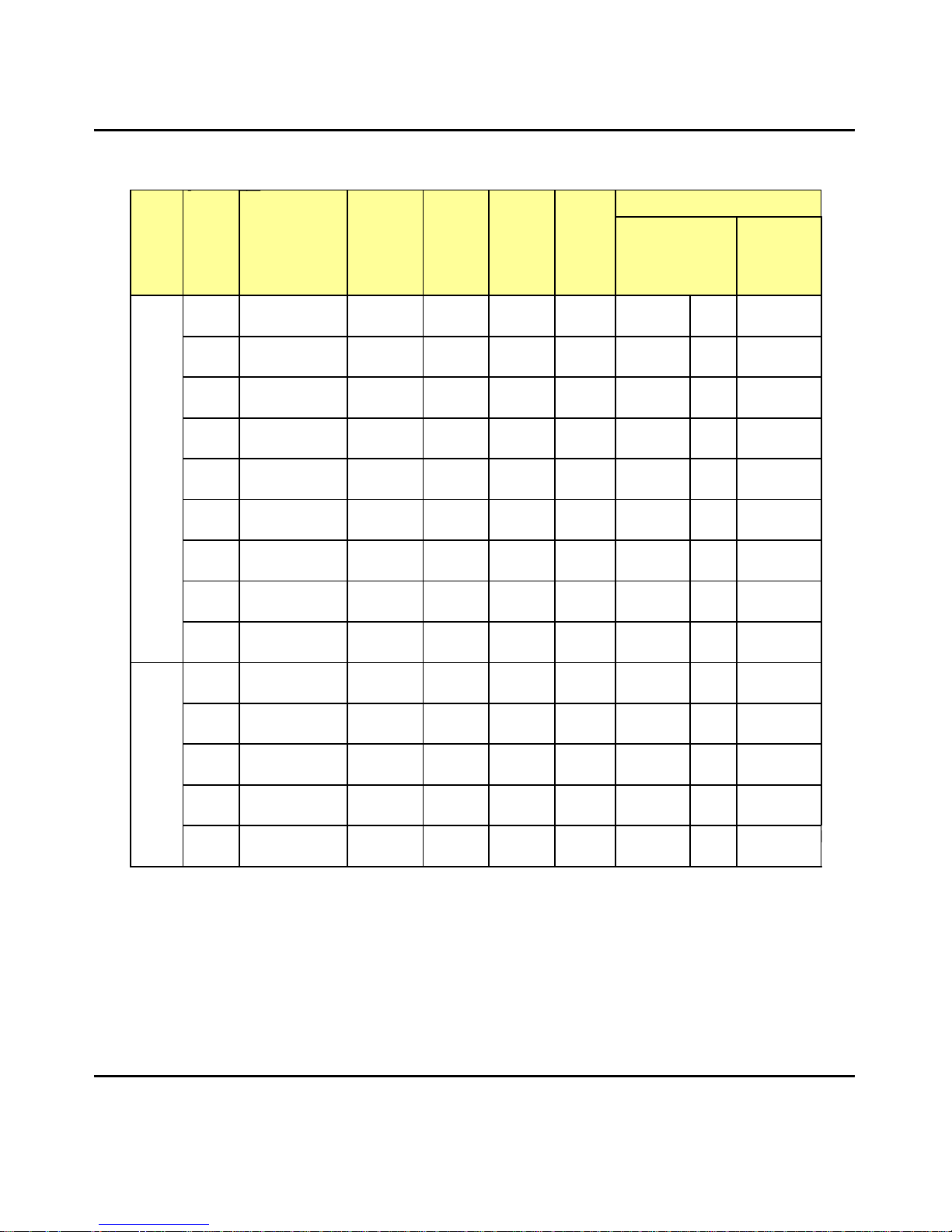
(4 ) Common applicable tools
Class
Motor
Output
㎾(HP)
Inverter
model
Power
lines
R,S,T
U,V,W,
P
(
mm
2
)
External
resister
between
P and
RB
(
mm
2
)
Screw
size
of
Terminal
Torque
(N•m)
Applicable Tools
Leak breaker
(MCCB)
Electro-
magnetic
Controller
(MC)
200V
Class
0.4
N700E-004SF
1.25 M3 0.5 HBS-33 5A HMC 10W
0.4
N700E-004LF
1.25 M3 0.5 HBS-33 5A HMC 10W
0.75
N700E-007SF
1.25 M3 0.5 HBS-33 10A HMC 10W
0.75
N700E-007LF
1.25 M3 0.5 HBS-33 10A HMC 10W
1.5
N700E-015SF
2 M4 1.2 HBS-33 15A HMC 10W
1.5
N700E-015LF
2 M3 0.5 HBS-33 15A HMC 10W
2.2
N700E-022SF
2 M4 1.2 HBS-33 20A HMC 20W
2.2
N700E-022LF
2 M4 1.2 HBS-33 20A HMC 20W
3.7
N700E-037LF
3.5 M4 1.2 HBS-33 30A HMC 20W
400V
Class
0.4
N700E-004HF
1.25 M4 1.2 HBS-33 5A HMC 10W
0.7
N700E-007HF
1.25 M4 1.2 HBS-33 5A HMC 10W
1.5
N700E-015HF
1.25 M4 1.2 HBS-33 10A HMC 10W
2.2
N700E-022HF
1.25 M4 1.2 HBS-33 10A HMC 10W
3.7
N700E-037HF
2.0 M4 1.2 HBS-33 15A HMC 20W
Table 2-6 Common applicable tools for N700E inverters
13
N700E INSTRUCTION MANUAL
N700E INSTRUCTION MANUALN700E INSTRUCTION MANUAL
N700E INSTRUCTION MANUAL
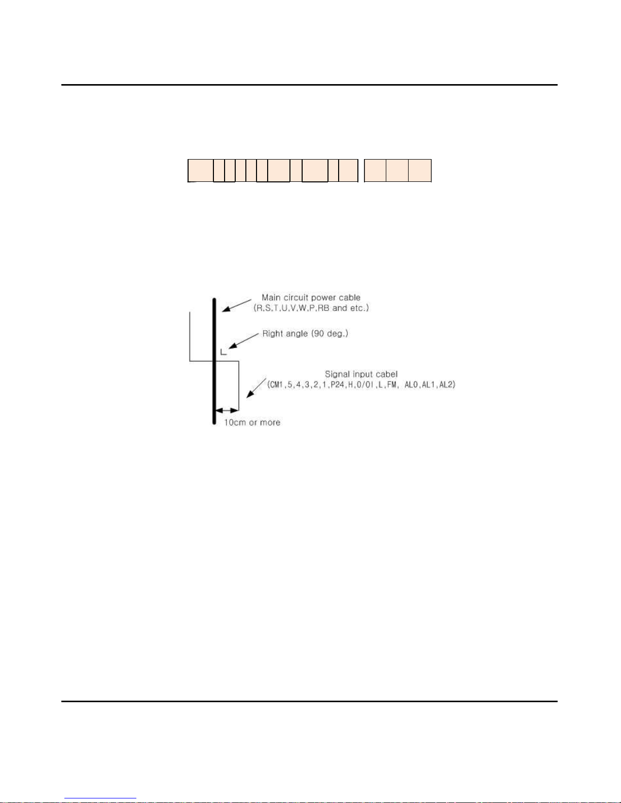
2.2.3 Terminal connection diagram
(1) Terminal connection diagram
5 The control circuit terminal of inverters is connected with the control board in unit.
CM1 5 4 3 2 1 P24 H O/OI L FM
AL
0
AL1 AL2
Fig 2-4 Terminal connection diagram
(2) Wiring
6 Both the CM1 and L terminals are insulated to both the common terminal of the input and output
signals. Do not short or connect to ground these common terminals.
7 Use twisted screened cable, for the input and output wires of the control circuit terminals.
Connect the screened cable to the common terminal.
8 Limit the connection wires to 65 feet.
9 Separate the control circuit wiring from the main power and relay control wiring.
10 When using relays for the FW terminal or an intelligent input terminal use a control relay that is
designed to work with 24Vdc.
11 Do not short the analog voltage terminals H and L or the internal power terminals PV24 and all
CM1’s. Otherwise there is risk of Inverter damage.
14
N700E INSTRUCTION MANUAL
N700E INSTRUCTION MANUALN700E INSTRUCTION MANUAL
N700E INSTRUCTION MANUAL
(3) Change of input logic type
• Selection switch
① SINK/SOURCE TYPE
- J1,J2 : SINK/SOURCE TYPE selection switch.
② The connection to the input programmable logic controller
Fig 2-6 Input terminal and PLC connection
15
To use interface power within inverter To use outside power
(Remove the short bar off of the control terminal.)
Sink Type
Output
modume
inverter
Short
COM
P24
PLC
CM1
FW
5
S
DC24V
Output
modume
inverter
COM
DC24V
P 24
PLC
CM1
FW
5
S
DC24V
Source Type
Output
modume
inverter
S
P24
PLC
CM1
1
5
DC24V
COM
Short
Output
modume
inverter
S
P24
PLC
CM1
1
5
DC24V
COM
DC24V
N700E INSTRUCTION MANUAL
N700E INSTRUCTION MANUALN700E INSTRUCTION MANUAL
N700E INSTRUCTION MANUAL
Operation
!
WARNING
Be sure not to touch the main terminal or to check the signal add or remove wires
and/or connectors.
Otherwise, there is a danger of electric shock.
Be sure not to turn the input power supply on until after front case is closed.
While the inverter is energized, be sure not to remove the front cover.
Otherwise, there is a danger of electric shock.
Be sure not to operate the switches with wet hands.
Otherwise, there is a danger of electric shock.
While the inverter is energized, be sure not to touch the inverter terminals even while
the unit is not running.
Otherwise, there is a danger of electric shock.
If the retry mode is selected, it may suddenly restart during the trip stop.
Be sure not to approach the equipment.(Be sure to design the equipment so that
personnel safety will be secured even if equipment restarts.)
Otherwise, there is a danger of injury.
Be sure not to select retry mode for up and down equipment or traveling equipment,
because there is an output free-running mode in term of retry.
Otherwise, there is a danger of injury and/or machine breakage
Even if the power supply is cut for a short period of time, the inverter may restart
operation after the power supply is restored if the operation command is given.
If a restart may incur danger to personnel, be sure to make a circuit so that it will not
restart after power recovery.
Otherwise, there is a danger of injury.
The stop key is valid only when a function is on. Ensure that there is a hard wired
emergency stop that is separate from the stop key of the inverter.
Otherwise, there is a danger of injury.
With the operation command on, if the alarm reset is ordered, the inverter can restart
suddenly. Be sure to set the alarm reset after checking the operation command is off.
Otherwise, there is a danger of injury.
Be sure not to touch the inside of the energized inverter or to put a bar into it.
Otherwise, there is a danger of electric shock and/or fire.
16
 Loading...