


Fuel System
General Information
Specifications .................................................. FL - 3
Troubleshooting...............................................FL - 5
Electronic Engine Control System
Description.......................................................FL -28
ECU
Components............................................... FL -31
Removal ..................................................... FL -35
Mass Air Flow Sensor
Inspection ................................................... FL -36
Differential Pressure Sensor(DPS)
Components............................................... FL -39
Description ................................................. FL -39
Specifications ............................................. FL -40
Part Circuit Diagram .................................. FL -40
Replacement .............................................. FL -41
Electronic Fuel Supply System
Components ....................................................FL -42
Injector
Components............................................... FL -43
Removal ..................................................... FL -44
Installation .................................................. FL -45
Replacement .............................................. FL -45
Cleaning..................................................... FL -45
Common Rail Assembly
Components............................................... FL -46
Removal ..................................................... FL -47
Installation .................................................. FL -47
Accelerator Pedal
Description ................................................. FL -48
Removal ..................................................... FL -48
Inspection ................................................... FL -48
Fuel Tank And Fuel Filter
Replacement .............................................. FL -49
Inspection ................................................... FL -50
Electronic Injection Pump
Supply Pump
Components............................................... FL -51
Removal ..................................................... FL -52
Installation .................................................. FL -53
DTC Troubleshooting Procedures
Basic Troubleshooting ..................................... FL -55
Schematic Circuit ............................................ FL -63
DTC List ........................................................... FL -80
P0072............................................................... FL -84
P0073............................................................... FL -88
P0088............................................................... FL -92
P0101............................................................... FL -98
P0102............................................................... FL -102
P0103............................................................... FL -106
P0107............................................................... FL -110
P0108............................................................... FL -112
P010A .............................................................. FL -114
P0112............................................................... FL -118
P0113............................................................... FL -122
P0116............................................................... FL -126
P0117............................................................... FL -129
P0118............................................................... FL -132
P0120............................................................... FL -135
P0121............................................................... FL -140
P0122............................................................... FL -145
P0123............................................................... FL -149
P0182............................................................... FL -153
P0183............................................................... FL -156
P0192............................................................... FL -159
P0193............................................................... FL -165
P0194............................................................... FL -171
P0195............................................................... FL -177
P0196............................................................... FL -183
P0201............................................................... FL -189
P0202............................................................... FL -195
P0203............................................................... FL -200
P0204............................................................... FL -205
P0217............................................................... FL -210
P0219............................................................... FL -212
P0220............................................................... FL -217
............................................................... FL -222
P0221
P0222............................................................... FL -227
P0223............................................................... FL -232
P0225............................................................... FL -236
P0226............................................................... FL -240
P0237............................................................... FL -244
P0238............................................................... FL -249
P0335............................................................... FL -254
P0336............................................................... FL -259
P0340............................................................... FL -264
P0341............................................................... FL -269
P0401............................................................... FL -274
P0403............................................................... FL -277
P0404............................................................... FL -280
P0405............................................................... FL -284
P0406............................................................... FL -288

P0501 ............................................................... FL -292
P0502 ............................................................... FL -297
P0503 ............................................................... FL -302
P0541 ............................................................... FL -307
P0542 ............................................................... FL -309
P0562 ............................................................... FL -312
P0563 ............................................................... FL -315
P0601 ............................................................... FL -318
P0602 ............................................................... FL -320
P0603 ............................................................... FL -322
P0604 ............................................................... FL -324
P0606 ............................................................... FL -326
P0607 ............................................................... FL -328
P0615 ............................................................... FL -330
P0627 ............................................................... FL -333
P0629 ............................................................... FL -337
P0642 ............................................................... FL -341
P0643 ............................................................... FL -344
P0652 ............................................................... FL -347
P0653 ............................................................... FL -349
P0698 ............................................................... FL -351
P0699 ............................................................... FL -354
P069E .............................................................. FL -357
P069F ............................................................... FL -360
P0704 ............................................................... FL -363
P0850 ............................................................... FL -366
P1120 ............................................................... FL -369
P1132 ............................................................... FL -374
P1133 ............................................................... FL -377
P1190 ............................................................... FL -380
P1218 ............................................................... FL -384
P1219 ............................................................... FL -388
P1221 ............................................................... FL -391
P1222 ............................................................... FL -397
P1223 ............................................................... FL -400
P1231 ............................................................... FL -403
P1232 ............................................................... FL -406
P1383 ............................................................... FL -409
P1384 ............................................................... FL -411
P1616 ............................................................... FL -414
P1642 ............................................................... FL -419
P1643 ............................................................... FL -422
P2002 ............................................................... FL -425
P2146 ............................................................... FL -427
P2147 ............................................................... FL -432
P2148 ............................................................... FL -437
P2149 ............................................................... FL -442
P2150 ............................................................... FL -448
P2151 ............................................................... FL -453
P2293 ............................................................... FL -458
P2413 ............................................................... FL -462
P2454 ............................................................... FL -466
P2455 ............................................................... FL -471
P2503 ............................................................... FL -476
P2504 ............................................................... FL -478
U0001 .............................................................. FL -480
U0010 .............................................................. FL -483
General Information
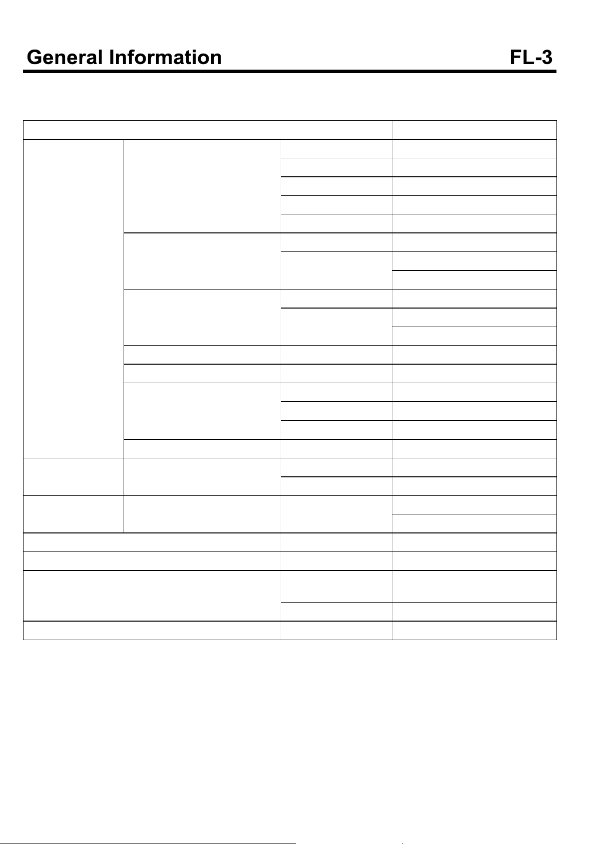
SPECIFICATIONS
Items Specification
Sensors BPS(Booster pressure sensor) Supply voltage 5V
Operating voltage 0.5~4.5 V
Operating temperature -40~125°C
Operating pressure 50~500 kpa
Current MAX. 10 mA
IAT(Intake air temperature) Type Thermistor
Resistance 2.31~2.56 k [At 20°C(68°F)]
0.30~0.34 k [At 80°C(176°F)]
WTS(Water temperature sensor) Type Thermistor
Resistance 2.31~2.59 k [At 20°C(68°F)]
0.314~0.331 k [At 80°C(176°F)]
TDC(Topdeadcenter)sensor Type Hall sensor
CKP(Crankshaft positon sensor) Type Magnetic
APS(Accel positon sensor) Type Variable resistance(Potentiometer)
Voltage 5V±1%
Current Max. 10 mA
Fuel pressure sensor Type Piezo electricity
Actuator Injector Type Electromagnetic
Resistance 0.45
Supply control valve SCV Current Active : Below 1.29 A
When stopped :Below 1.16 A
Fuel tank Capacity 100 L
Fuel pressure of high pressure side Max. pressure 1,800 bar
Supply pump Type Included into high pressure pump
mechanical type
Power Mechanical gear type
Fuel filter Type Filter

EGR Valve specification
Items Specification
Valve type Flap type
Control type Electric DC motor
Sealant
Water temperature sensor(Coolant temperature sensor) Loctite 200 or equivalent
Inspection
Item Reference value
Idle speed(rpm) 650±25
Tightening torque
Items Kgf.m N.m lb-ft
ECM mounting bolt 1.9~2.8 18.6~27.4 13.8~20.4
Mass air flow sensor mounting bolt 0.8~1.2 7.8~11.8 5.8~8.7
Crankshaft position sensor mounting bolt 0.8~1.2 7.8~11.8 5.8~8.7
TDC sensor mounting bolt 0.8~1.2 7.8~11.8 5.8~8.7
EGR valve mounting bolt(Inlet pipe) 1.0~1.4 9.8~13.7 7.2~10.1
EGR valve mounting bolt(EGR cooler) 1.0~1.4 9.8~13.7 7.2~10.1
High pressure pipe(rail-injector 1,2,3,4,5,6) 4~5 39~49 29~36
Common rail assembly mounting bolt 1.9~2.8 18.6~27.4 13.8~20.4
Fuel filler pipe assembly mounting bolt 0.8~1.2 7.8~11.8 5.8~8.7
Fuel return pipe mounting bolt 0.8~1.2 7.8~11.8 5.8~8.7
Fuel supply pump flange mounting bolt 10~13 98.6~128 72.3~94
Fuel supply pump mounting bolt 1.9~2.8 18.6~27.4 13.8~20.4
Injector clamp bolt 2.9~3.1 28.42~29.4 21~22.4
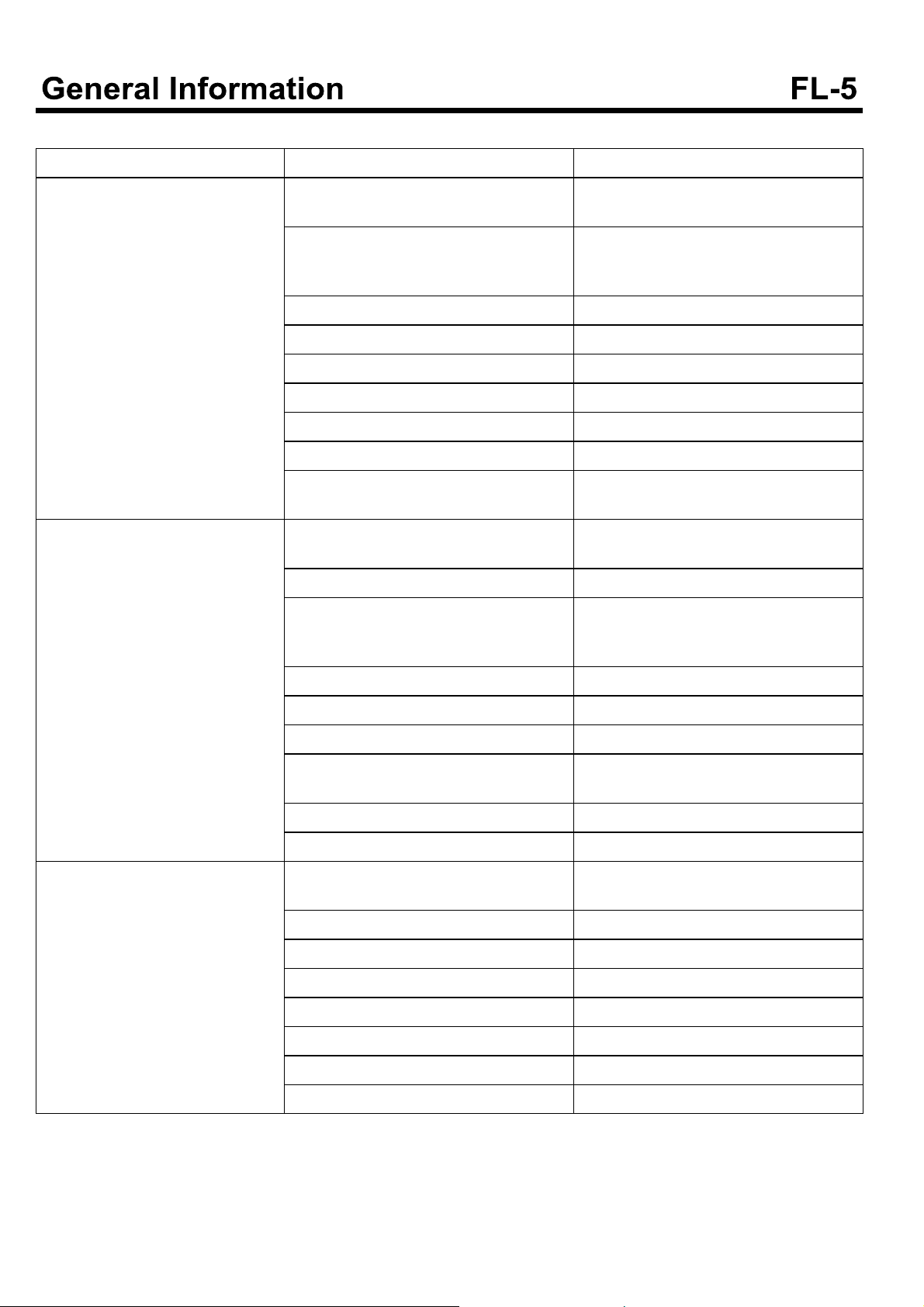
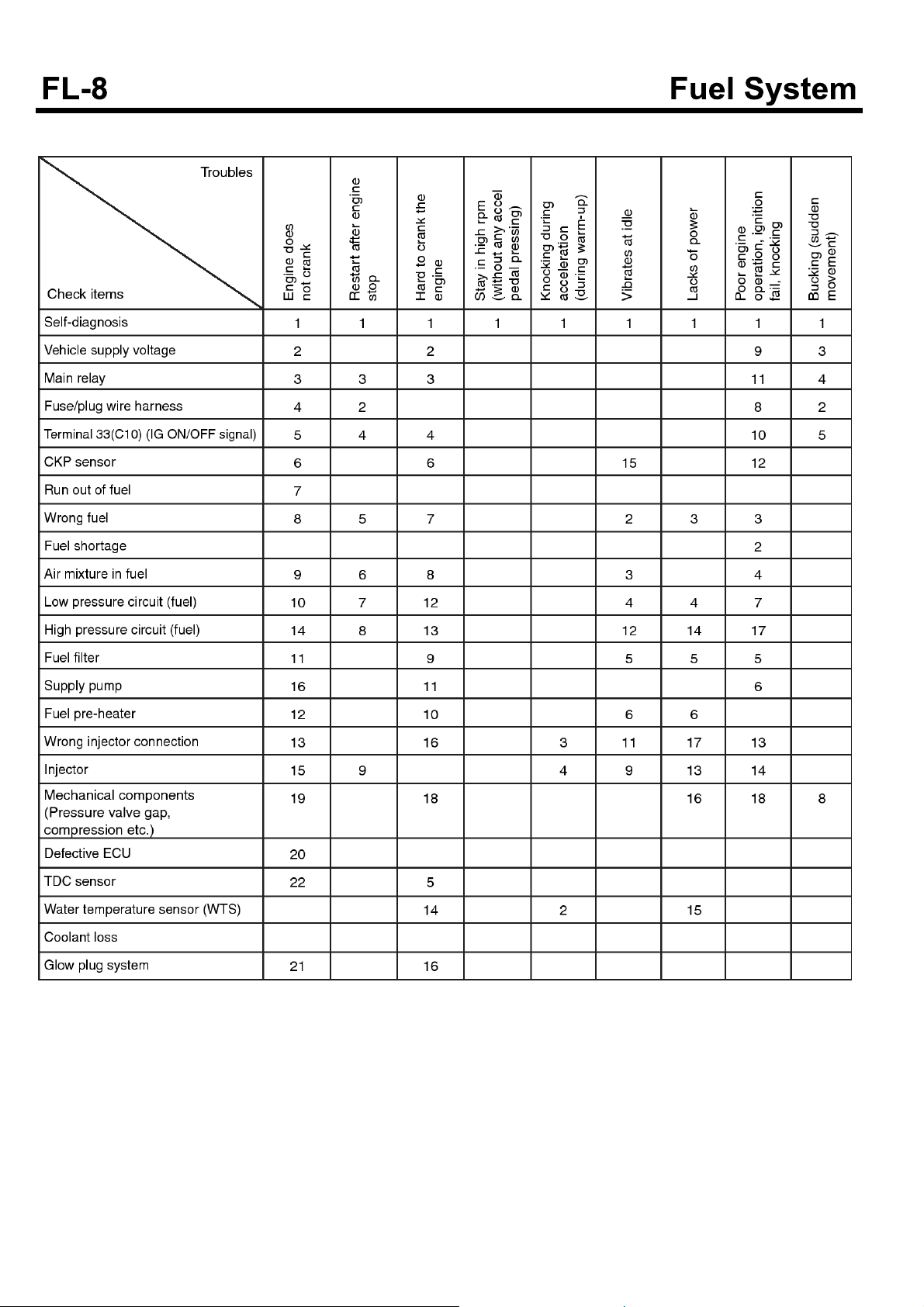
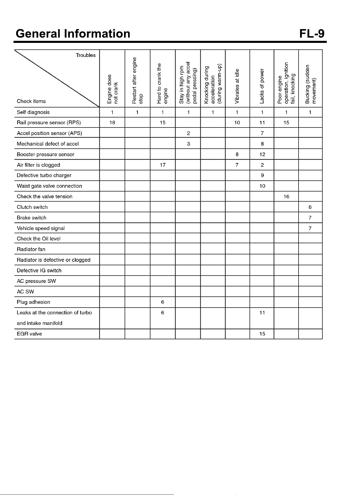
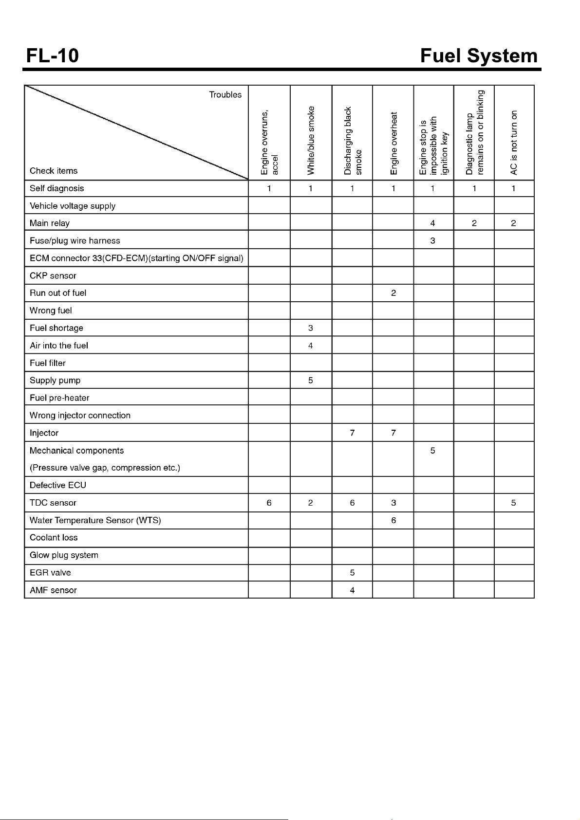
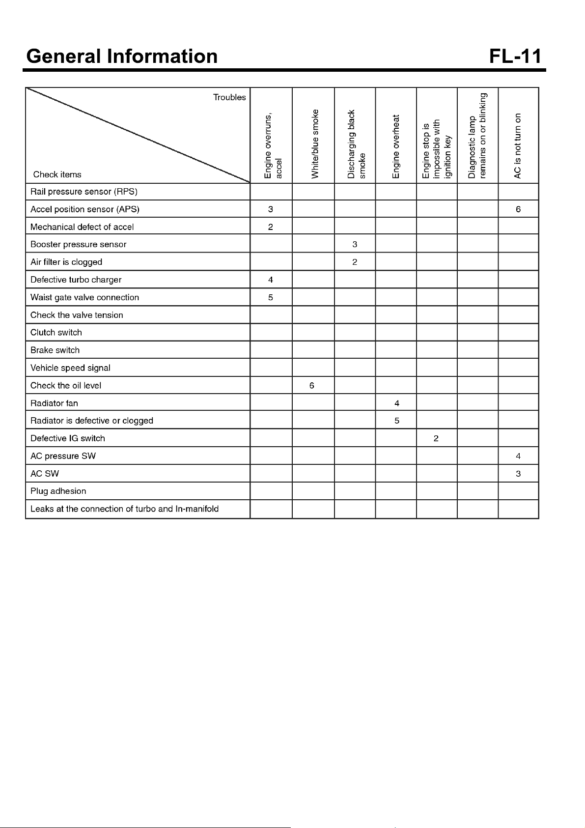
TROUBLESHOOTING
Symptom Possible causes Remedy
Engine does not crank.
Idle is improper or idle speed is unstable or irregular.
Low cranking speed
Low voltage to glow plug system If the test light turns on indicating low vo-
Defective glow plug Replace the glow plug.
Air in the fuel system Air bleeding of fuel system
Injection pipe is connected incompletely. Connect the pipe correctly
Improper injection timing Check ECM.
Poor injection Check, replace injector.
Mechanical defect of engine Test compression, repair engine.
Simultaneous failures of TDC sensor and
CKP sensor
Loose fuel hose connection between filter and supply pump.
Air in the fuel system Air bleeding of fuel system
Fuel filter is clogged. Or fuel supply is no
good because fuel line or injection pipe leaks, pinched or pressed.
Repairthestarterorchargeorreplacebattery.
ltage when it turns “ON”, check relay and
wiring.
Check and tighten correctly.
Tighten or repair.
Check hose or fuel line. Replace fuel filter if necessary.
Poor injection Check, replace injector.
Improper injection timing Check ECM.
Mechanical defect of engine Test compression, repair engine.
Defective supply pump
Engine defect at high gear range Observe correct shift speed.
EGR valve malfunction Check or replace EGR valve.
Exhaust gas (Black, blue, white) Engine temperature stays below engine
operating temperature.
Abnormal at max. RPM Check and replace supply pump.
Defective Injection nozzle Check and repair or replace.
Improper injection timing Check ECM.
Exhaust system malfunction Check for deformed or clogged.
Mechanical defect of engine Test compression, repair engine.
Defective supply pump Replace supply pump.
EGR valve malfunction Check or replace EGR valve.
Let the engine at idle after replacing pump.
Check cooling system. Replace thermostat.
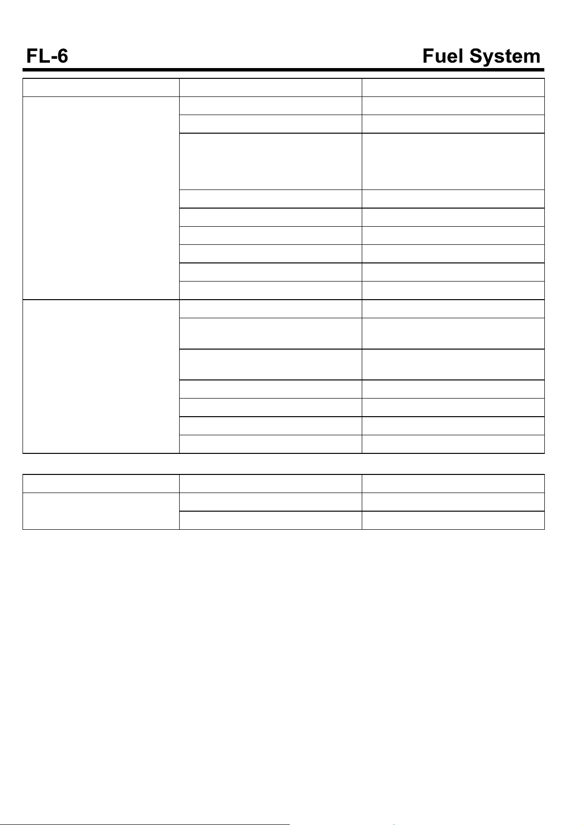
Symptom Possible causes Remedy
Engine lacks power, acceleration is delayed(Speedometer is normal,
no clutch slip)
Excessive fuel consumption Contaminated air cleaner filter Clean, replace air cleaner filter.
Abnormal at max. RPM Check, replace supply pump.
Contaminated air cleaner filter Clean or replace.
Fuel filter is clogged. Or fuel supply is no
good because fuel line or injection pipe leaks, pinched or pressed.Or fuel filter leaks.
Air in fuel system Air bleeding of fuel system
Defective supply nozzle Check, repair or replace.
Improper injection timing Check ECM.
Mechanical defect of engine Test compression, repair engine.
Defective injection pump Check after replacing pump.
EGR valve malfunction Check, replace EGR valve.
Fuel leaks Check all pipes, hoses and connection.
Clogged return pipe and hose. Check and replace the return line, blow
Defective injection nozzle Check. Repair or replace.
Check hose or fuel line. Replace fuel filter if necessary.
Replace or tighten as required.
air if clogged and drain the fuel.
Mechanical defect of engine Compression test, replace engine.
Defective supply pump Replace pump.
EGR valve malfunction Check or replce EGR valve.
Engine control
Symptom Possible causes Remedy
Engine will not turn off. Injector wiring short Check injector wiring.
Starting switch harness is damaged. Replace.
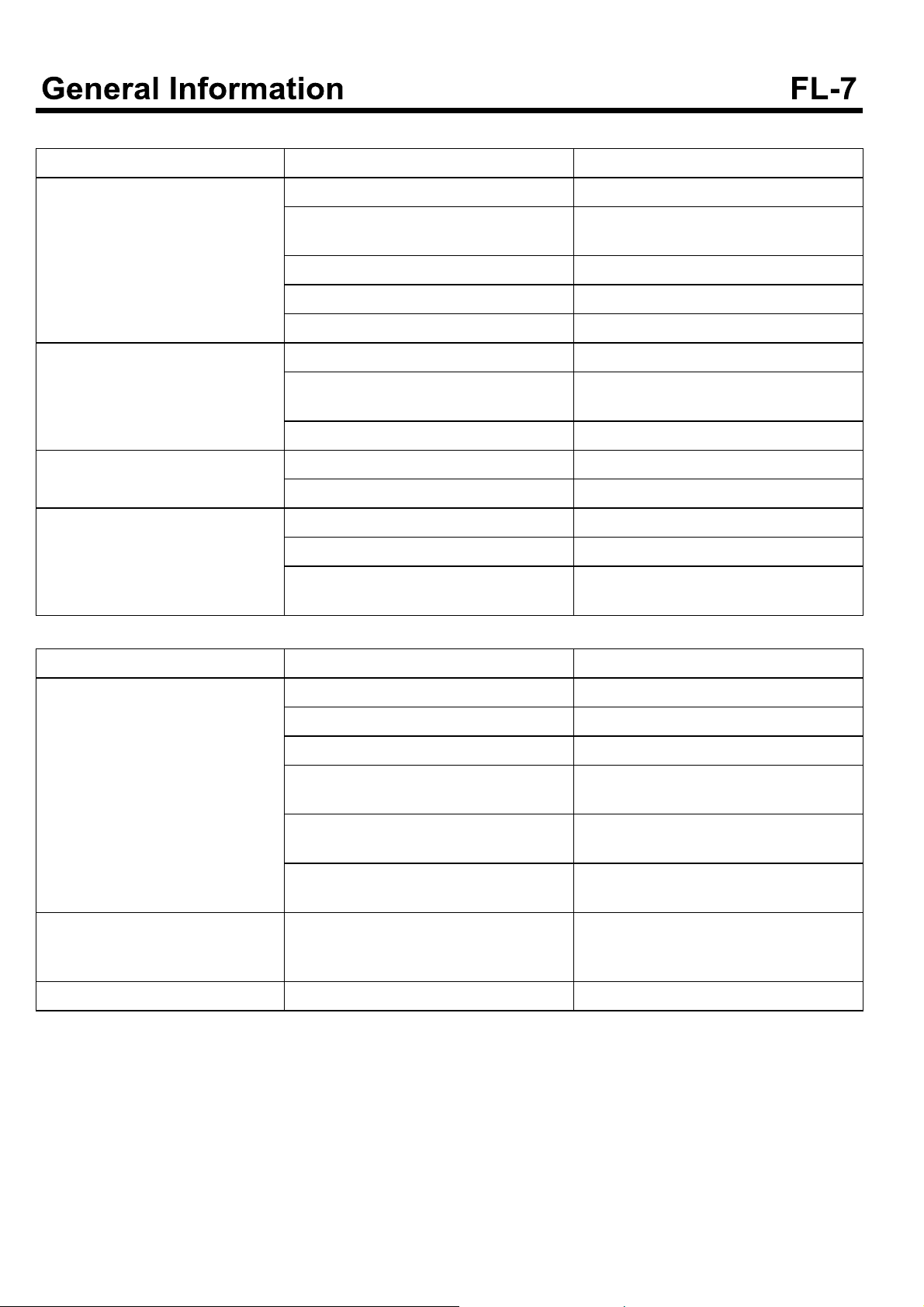
Engine starting system
Symptom Possible causes Remedy
Engine does not crank Low battery voltage Recharge or replace the battery.
Battery cable connection is loose, corroded or worn.
Fusible link is swelled. Replace the fusible link.
Defective starter motor. Repair.
Defective injector Replace.
Cranking speed is low Low battery voltage Recharge or replace the battery.
Battery cable connection is loose, corroded or worn
Defective starter motor Repair
Starter motor continues to run. Defective starter motor Repair
Defective ignition switch Replace the ignition switch.
Starter motor runs but engine is not cranking.
Defective wiring Repair wiring.
Starter motor, pinion gear damaged Repair starter motor.
Ring gear damaged Replace flywheel or torque converter ge-
Replace or retighten.
Repairorreplace.
ar.
Fuel tank and fuel line
Symptom Possible causes Remedy
Poor engine performance due to insufficient fuel supply
Fuel filter warning lamp blinks. Excessive water is in fuel filter. Drain the water collected in the fuel filter
Engine check lamps blinks. Clogged fuel filter. Replace fuel filter.
Fuel pipe is twisted or bended Repair or replace.
Fuel pipe or hose is clogged Clean or replace.
Fuel filter is clogged Replace.
Entry of water to fuel filter Replace fuel filter or clean fuel tank or f-
uel line.
Foreign materials intrude in fuel tank.
Fuel tank rusts.
Defective supply pump operation
(Clogged filter in pump)
Clean or replace.
Replace.
(Loosen the drain plug at the bottom of fuel filter.)
Troubleshooting procedure
SDGFL9001L
SUDFL9001L
SUDFL9002L
SDGFL9004L
SERVICE PROCEDURE
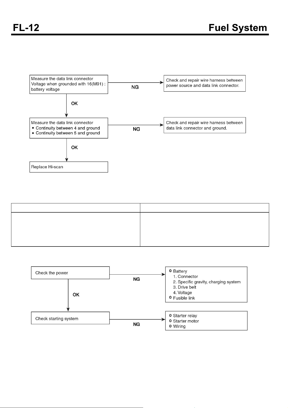
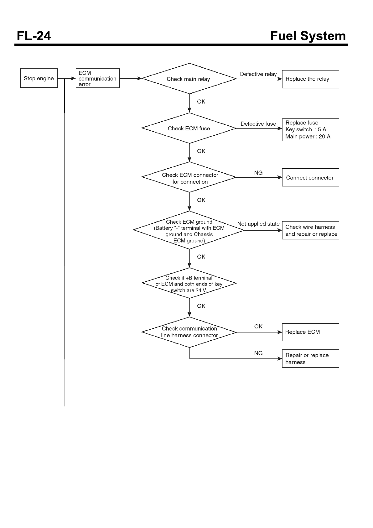
Communication with diagnosis equipment is not possible
(Impossible communication with all systems)
When communication between diagnosis equipment and
ECM is not possible
Trouble symptoms
It shows at least one of the following symptoms.
When power is not supplied to ECM,
ECM ground circuit is defective.
Defective ECM
Wrong communication line between ECU and Hi-scan
Engine does not start.
SDGFL9005L
Probable causes
Power supply circuit to ECM is defective.ECM
Malfunction ECM
Circuit between ECU and DLC is open.
SDGFL9006L
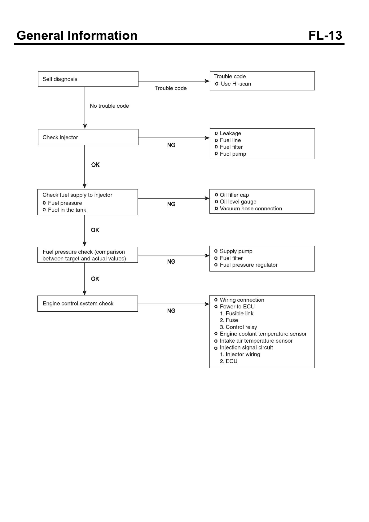
It is difficult to start the engine. (Possible cranking)
SDGFL9007L
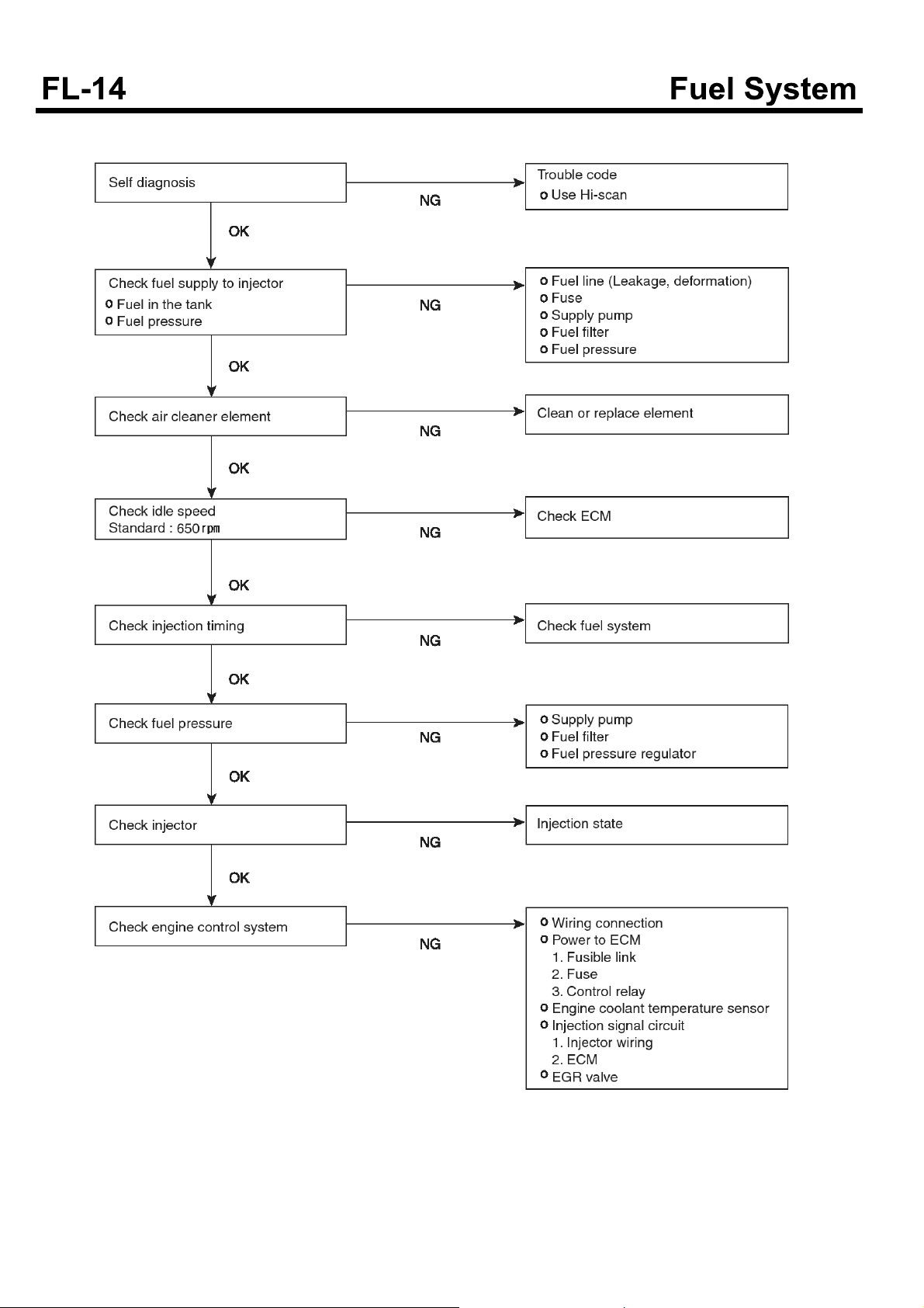
Unstable idle or engine stall.
SUDFL9003L
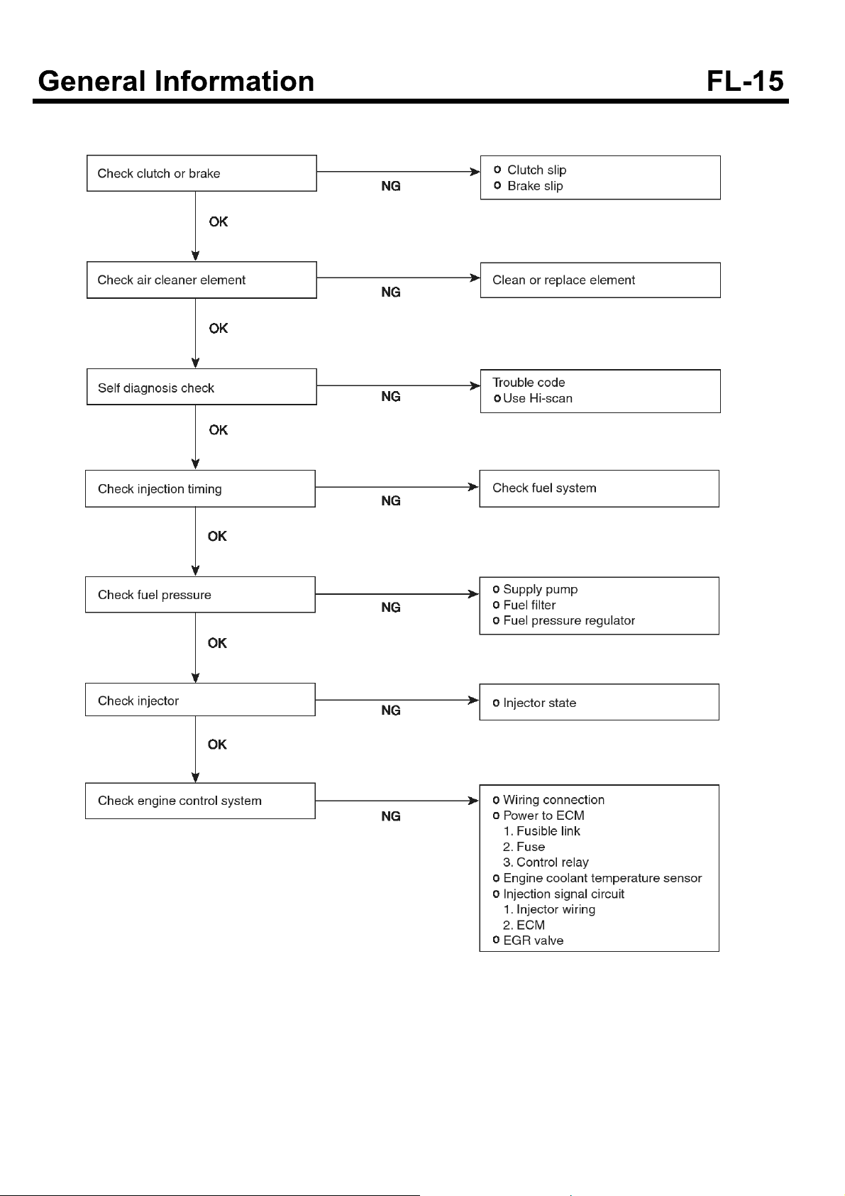
Engine hesitation or poor acceleration
SDGFL9009L
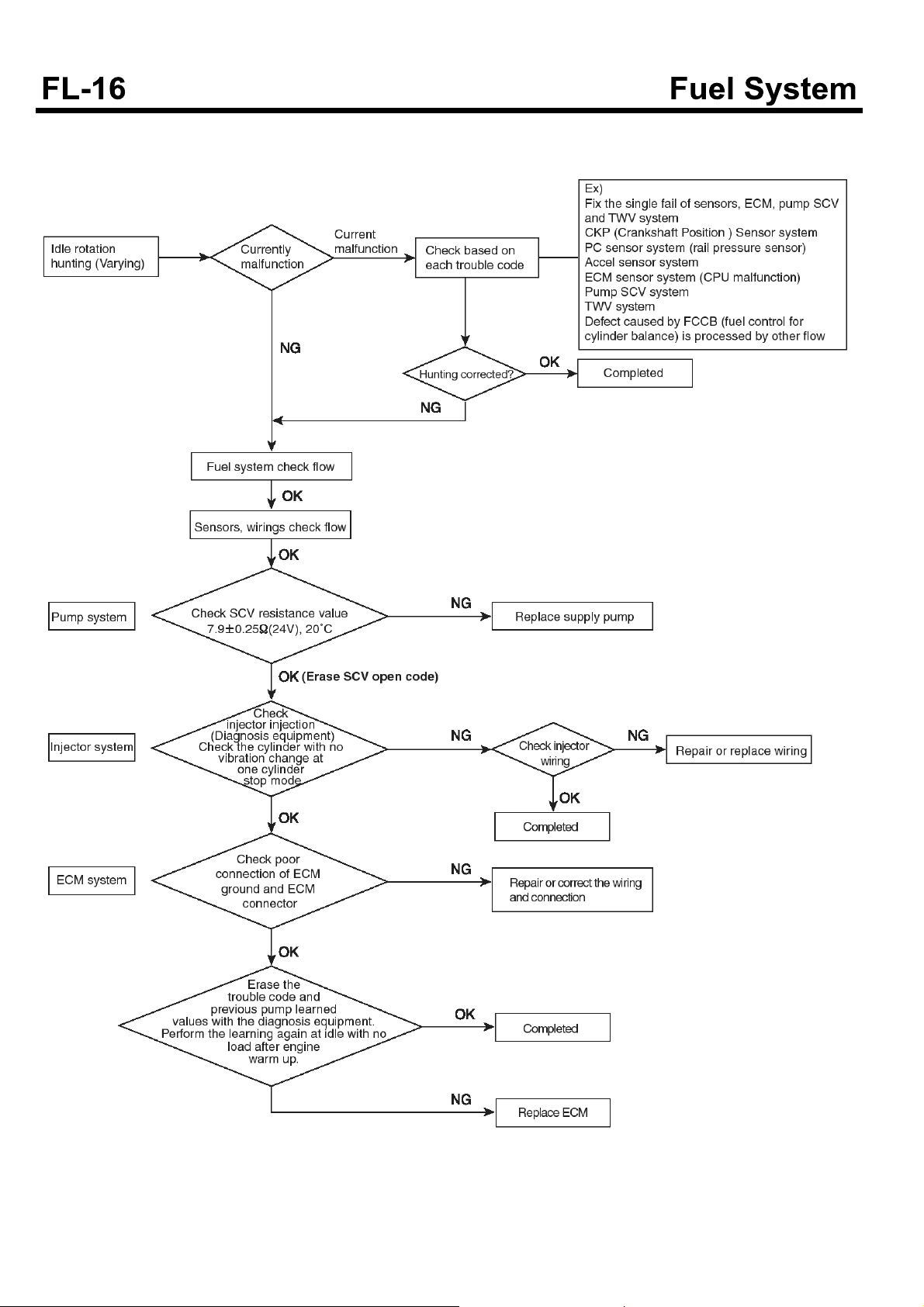
Troubleshooting flow chart when HUNTING(Varying)
occurs
SUDFL9004L
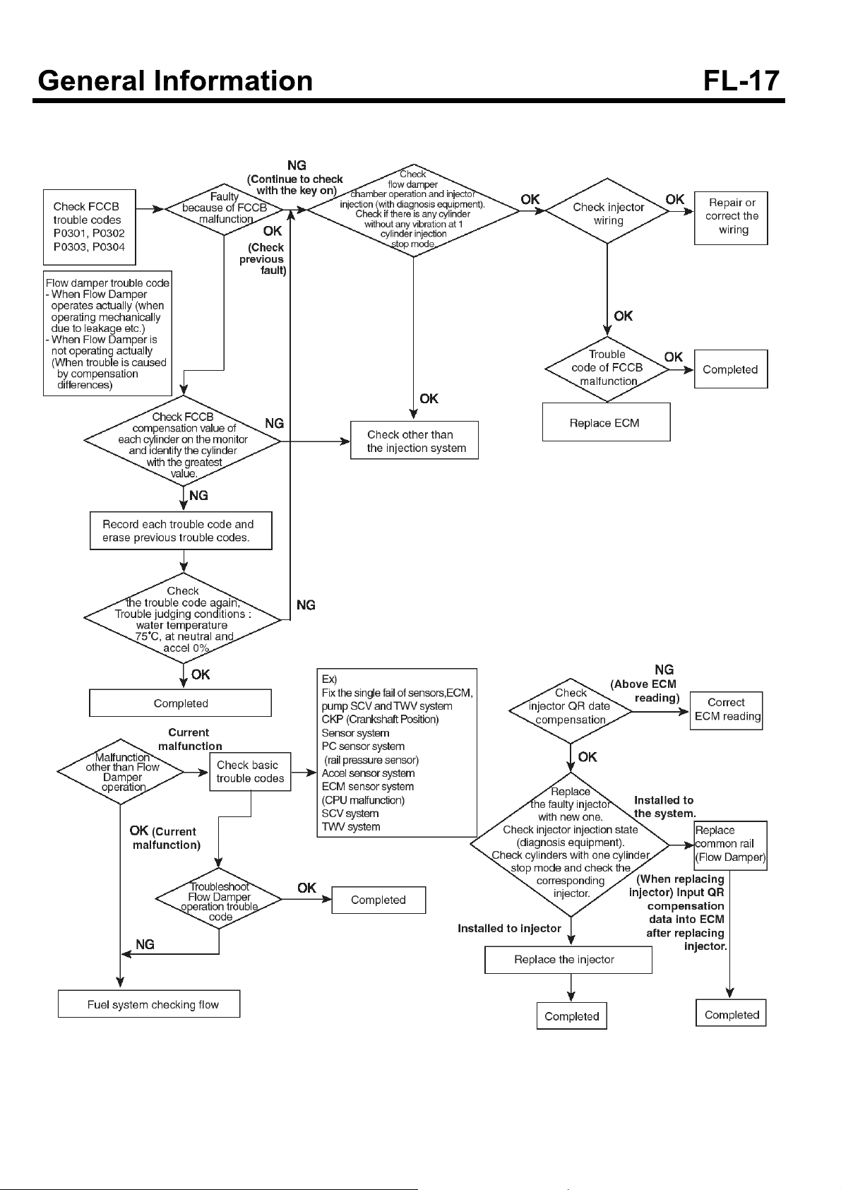
Troubleshooting flow chart when FCCB(Fuel control
cylinder balance) fails.
SUDFL9005L
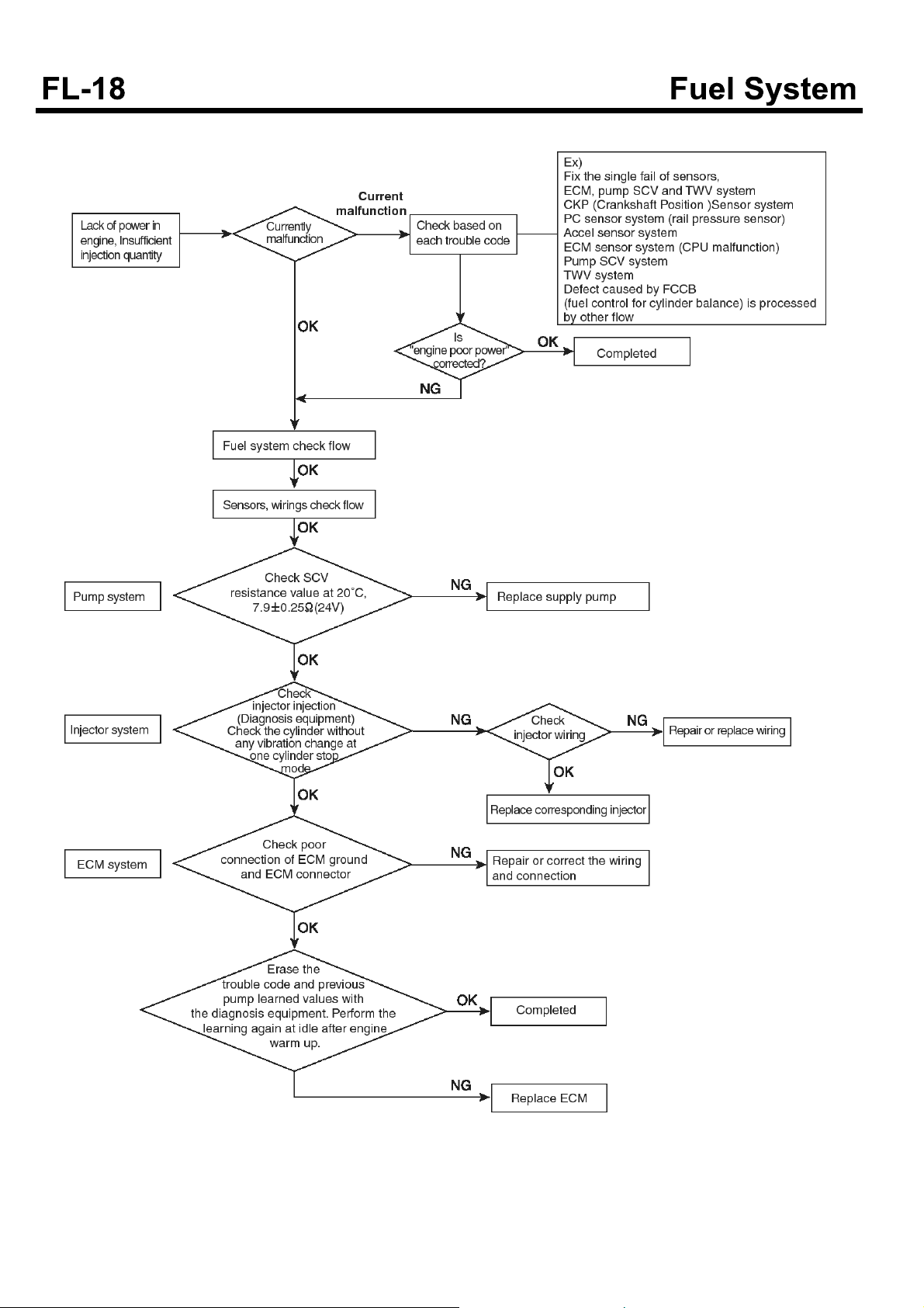
Troubleshooting flow chart when engine is lack of power
SUDFL9006L
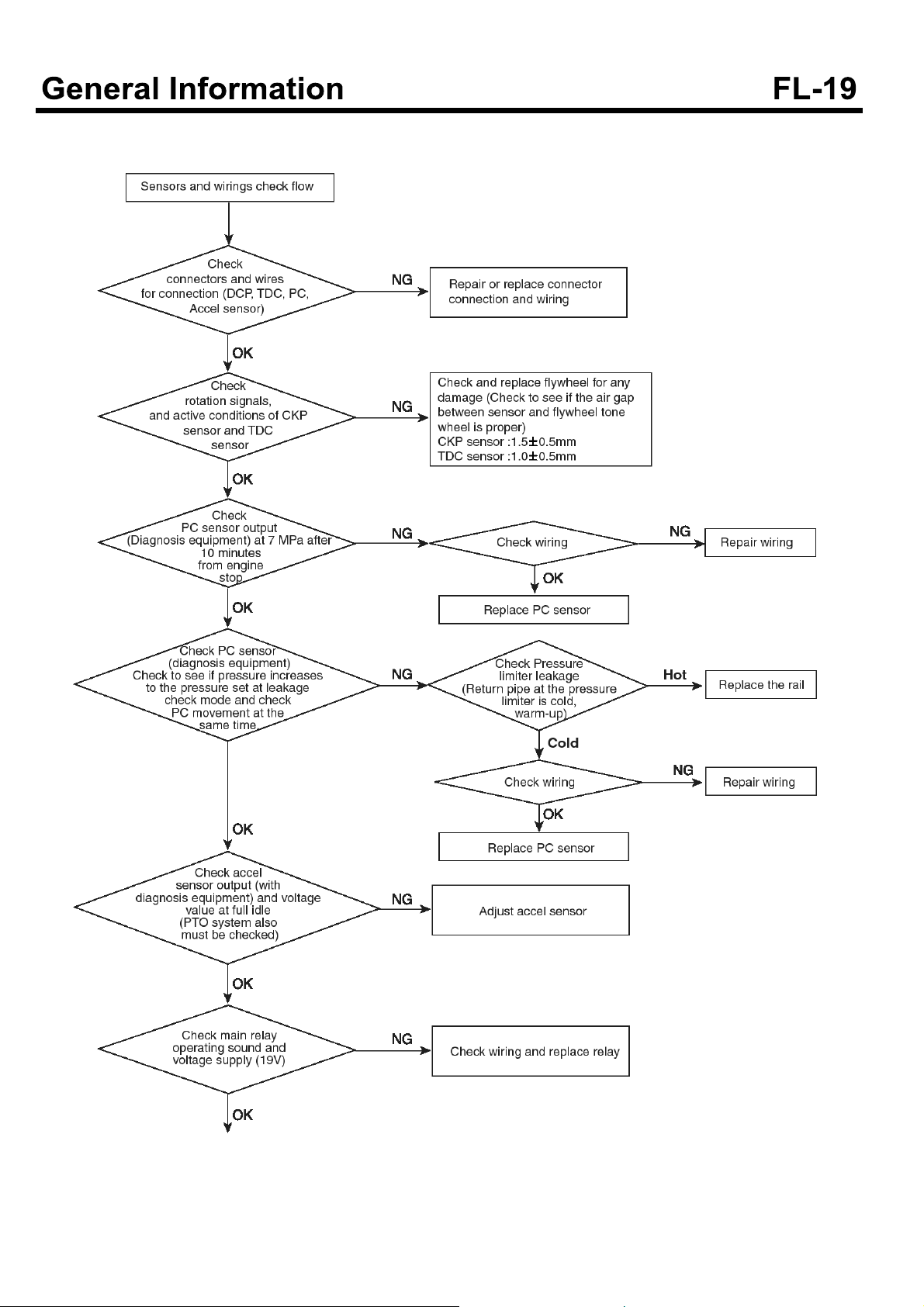
Troubleshooting flow chart in systems of sensors and
wirings
SDGFL9013L
CRS RAIL PRESSURE CHECK
■
Items to check in the vehicle
1. Check for customer complaint and trouble symptoms.
2. Check reoccurrence or not for customer complaint
and trouble symptoms mentioned above.
3. Record DTC codes or record the detailed DTC codes
by using Hi-scan.
Inspect and repair causes due to DTC codes.
4. Check rail pressure when turning ignition key to
NO(Engine OFF).
If the rail pressure is displayed, check it according to
inspection procedure of remaining pressure.
5. Check for connector of rail pressure sensor.
Check for wiring tension between rail pressure
sensor and connector of vehicle side.
Check that wiring between rail pressure sensor and
connector of vehicle side is tight or not due to
vibration(under driving) with interference in bracket of
engine/vehicle etc.
Check rail pressure sensor wire for clamp conditoin.
Check that wire of rail pressure senor is clamped
securely or not.
Check rail pressure sensor and connector of vehicle
side for connection conditon.
With connector connected, check connector for
shaking(with right and left/ back and forth).
7. Visual check of connector
Check each terminal contact part of rail pressure
sensor for wear.
Check connector housing of rail pressure sensor for
wear.
Check locking part/ guide part of rail pressure sensor
connector for damage or deformation.
Check the inside of rail pressure sensor connector for
foreign materials(such signs as water, oil, spark,
tracking etc.).
Check the opposite connector for foreign materials,
wear, damage, existence or not of rubber seal or
shrinkage of rubber seal etc..
If there is free play, check for output of rail
pressure/rail pressure sensor using Hi-scan or
oscilloscope.
6. Check for wiring related to the output of rail pressure
sensor.
Check for voltage between each terminal of rail
pressure sensor in the ECM side and terminal (-) of
battery.
Check wire between rail pressure sensor and ECM
for continuity(resistance).
SDGFL9014L
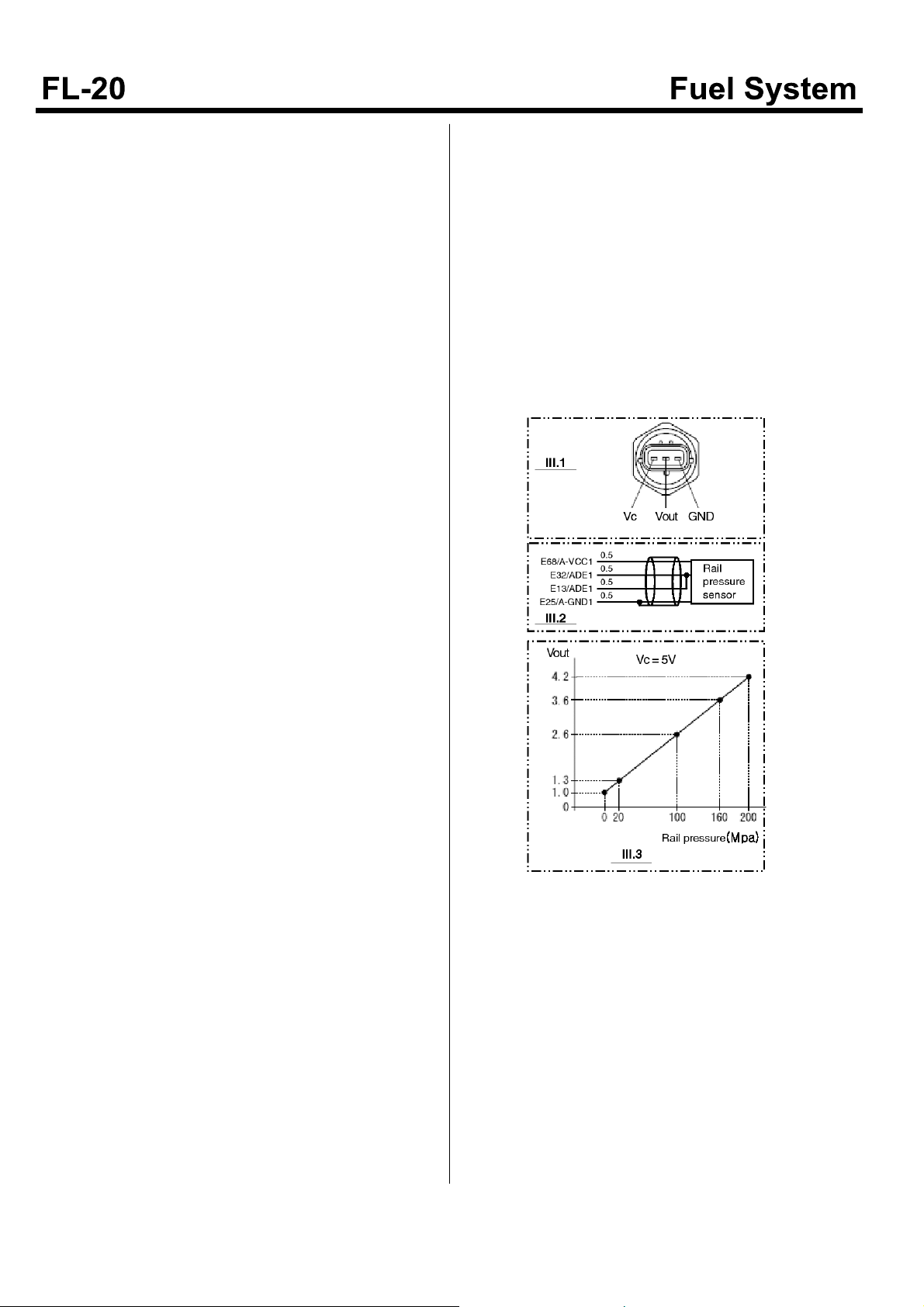
Rail pressure sensor
terminal
Voltage check
Check wiring between rail pres -
sure sensor and ECM
Measured v-
Item Pin No. Check condition
ECM terminal side r-
eference value
alue noise
or
Reference value/me-
asured condition
not
Vc E68 Key On 4.9~5.1 Below 2[ohm]/Key Off
Measured
value
Vout E32
Key On/EngineOff 0.9~1.1 Below 2[ohm]/Key Off
Engine On/at Accel. Refer to illustration 3 Below 2[ohm]/Key Off
Key On/Engine Off 0.9~1.1 Below 2[ohm]/Key Off
Vout E13
Engine On/at Accel. Refer to illustration 3 Below 2[ohm]/Key Off
GND E25 Key On 0±0.1 Below 2[ohm]/Key Off

CRS Rail pressure check flow chart
SDGFL9015L

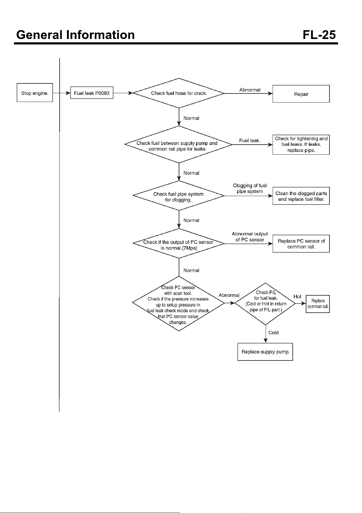
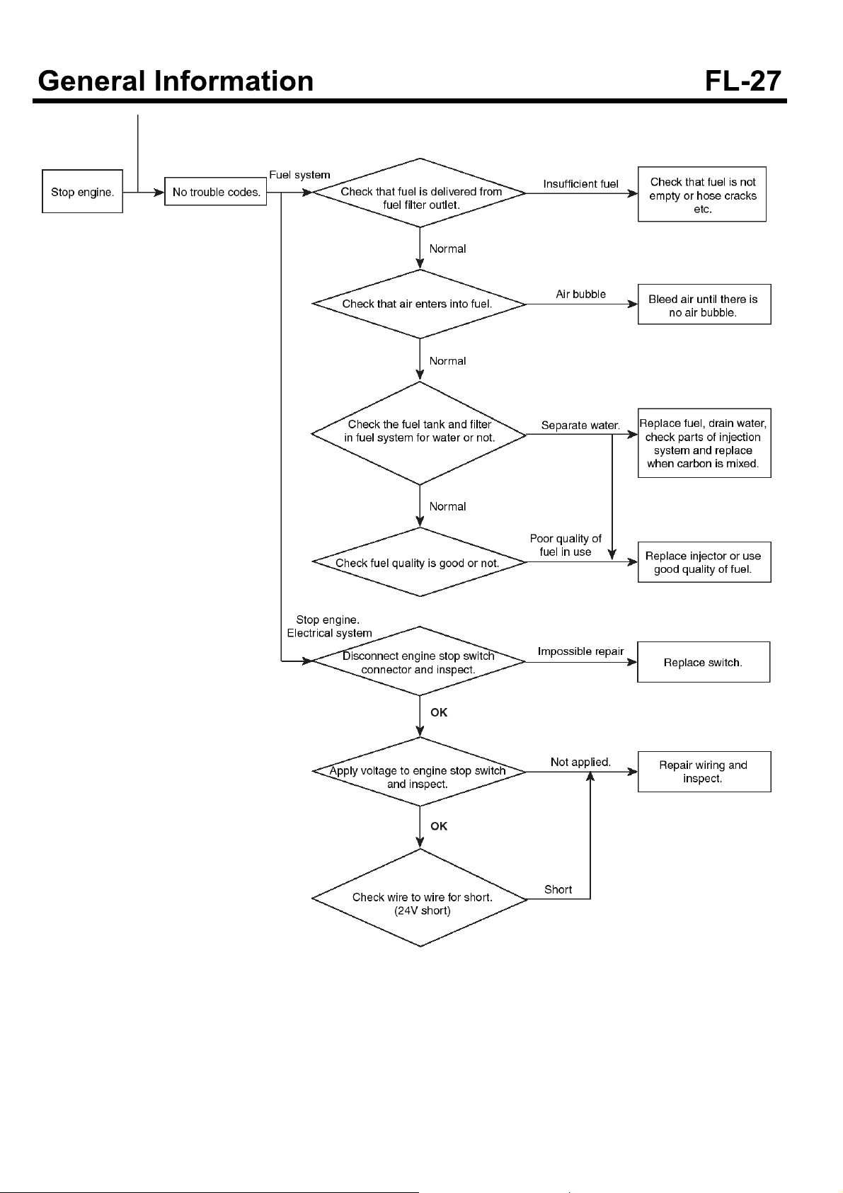
Fuel system check processor
SUDFL9007L
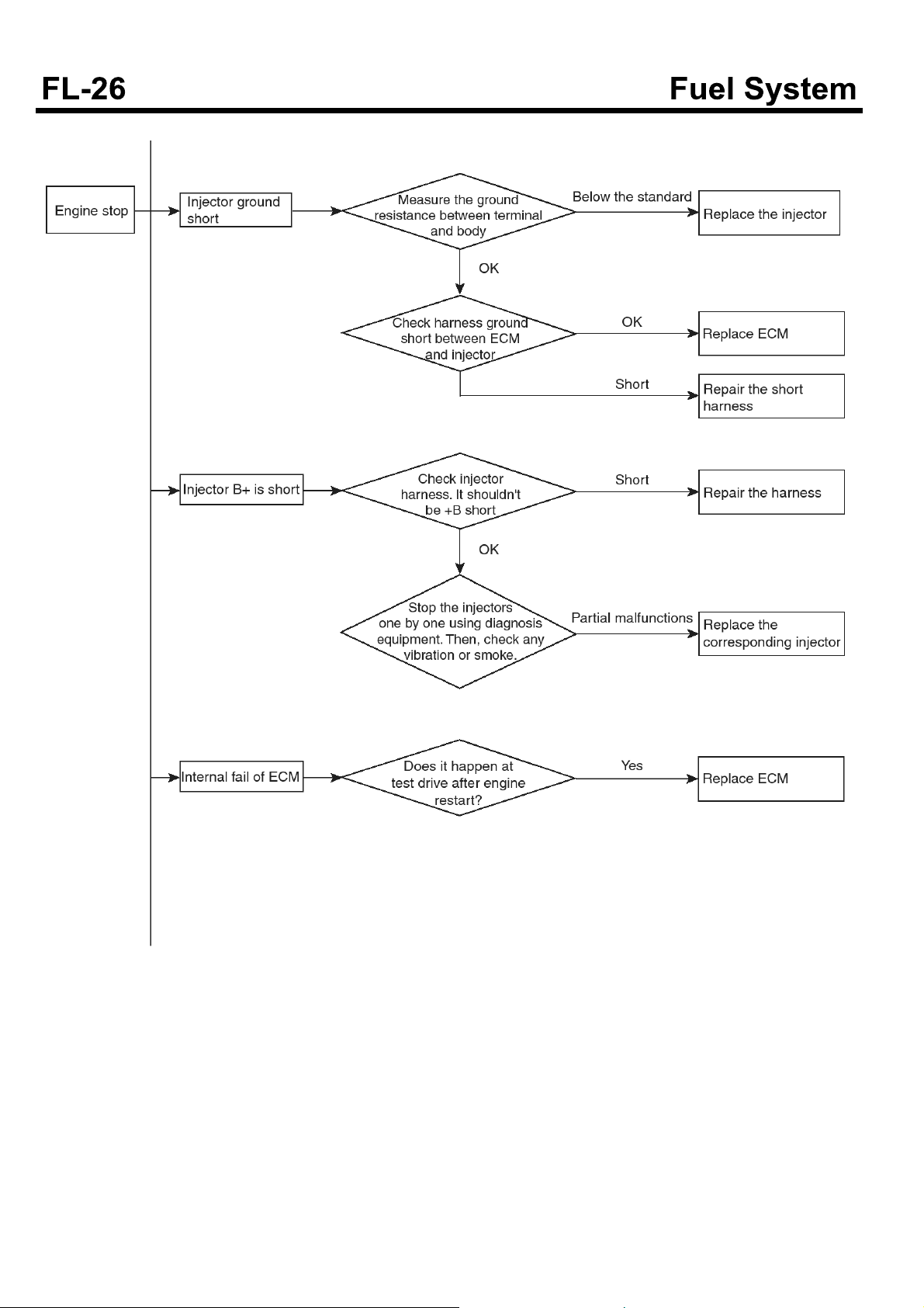
Troubleshooting flow chart when the engine stops
SUDFL9008L
SUDFL9009L
SDGFL9019L
SUDFL9010L
Electronic Engine Control System
DESCRIPTION
DIESEL CONTROL SYSTEM
Inspection of the diesel control system
If the components of the diesel control system (sensor,
ECM, injector etc.) have a problem, the proper amount of
fuel for various engine-operating conditions can not be
supplied and also the following situations can occur.
1. It is hard to start the engine or does not start the
engine at all.
2. Idling is unstable.
3. Engine driving performance is bad.
If any of the above conditions are met, first perform a
routine diagnosis that includes basic engine checks
(ignition system malfunction, incorrect engine
adjustment etc). Then, inspect the components of the
diesel control system with multi-purpose tester or
digital multi-meter.
CAUTION
Before removing or installing any part, read t he
diagnostic trouble codes and then, disconnect
the battery negative (-) terminal.
Before disconnecting the cable from battery
terminal, turn the ignition switch to OFF. If the
battery cable is removed or connected during
engine operation or the situation in which the
ignition switch is ON, then the ECU
semiconductor could be damaged resulting in
inaccurate operation.
Self-diagnosis
The ECM sends the input/output signals to various parts
of engine(some signals at all times and the others under
specified conditions).
After the specific time elapses the first detection of
irregular signal, the ECU judges this as an irregularity
and it records the diagnostic trouble code. And then it
sends the signal to the self-diagnosis output terminal.
The diagnosis results can be checked by the Hi-scan. In
addition, Diagnostic Trouble Codes (DTC) will be directly
backed up by the battery so that it will remain in the ECM
even if the ignition switch is turned off. The diagnostic
trouble codes will, however, be erased when battery
terminal or ECM connector is disconnected.
negative terminal (-) is disconnected for 15 seconds
or more, then the diagnosis memory will be erased.
Self-diagnosis check procedure
CAUTION
As DTC code may not be detected due to low battery
voltage, the battery condition should be checked
prior to inspection.
Since DTC code is erased if the battery or the ECM
connector is disconnected, don't disconnect the
battery until the diagnostic trouble codes are
completely read and recorded safely.
It is most desirable to erase the diagnostic trouble
codes using Hi-scan after completing check and
repair. After disconnecting ground cable from the
battery negative ( -) terminal for 15 seconds or more,
reconnect the cable and check if the trouble codes
have been erased. (At this time, ignition switch must
be turned off).
Inspection procedure (Using Hi-scan)
1. Turn off the ignition switch.
2. Connect the Hi-scan connector to the connector of
DLC (Data Link Connector) for the trouble diagnosis
as shown in the figure.
3. Turn the ignition switch ON.
4. Check the diagnostic code using Hi-scan.
5. Repair the parts having faults shown in the diagnosis
chart.
6. Erase the diagnostic trouble codes.
7. Disconnect the Hi-scan.
CAUTION
If, in most of diesel control system, the connector
of a sensor is disconnected with the ignition switch
turned ON, the diagnostic trouble code (DTC) is
recorded in the ECM. In this case, if the battery
KDDFL5019A

NOTICE
When using a tester manufactured by other
company, operate the tester by referring to the
manual of the company.
When erasing the diagnostic trouble codes, use
Hi-scan if possible. Though DTC can be erased by
disconnecting the battery terminal, doing so, the
data for learning control in ECM would be erased at
the same time.
DIESEL CONTROL SYSTEM COMPONENTS
LOCATION
1. Intake air temperature sensor and intake air pressure
sensor
3. Water temperature sensor(Coolant temperature
sensor)
SDFFL7505D
4. Camshaft sensor
2. Crankshaft position sensor
SDFFL7503D
SDFFL7506D
5. Injector(A)
SDFFL7504D
SDFFL7009D
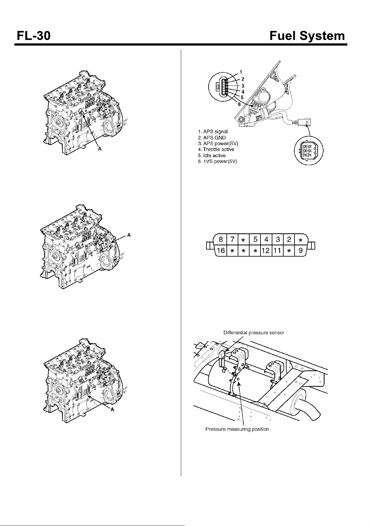
6. Rail pressure sensor(A)
9. Accelerator position sensor
7. Supply control valve(SCV, A)
8. ECM(Engine control module, A)
SDFFL7006D
SDFFL7007D
SUDFL9016L
10. DLC connector
SDFFL7314D
11. DPS(Differential Pressure Sensor)
SDFFL7008D
SUDFLDTC9108L

ECU(Engine Control Unit)
COMPONENTS
ECM PIN CONNECTOR
SUDFL9011L

Vehicle side(80pin connector) - ECM connector(CFD-ECM)
Termi-
nal
1
2 PWR-ACT1 - 42 SWV23 Stop lamp switch
3 OUTV1 Main relay 43 SWV21 Self-diagnosis switch
4 OUTV2 Exhaust brake relay 44 SWV19 Cruise main ON/OFF switch
5 OUTV3 Starter relay 45 A-ground 10 Sensor ground10
6 SOUT6
7 SOUT4 Glow lamp 47 ADV1 Accelerator position sensor 1
8 SOUT2 PTO lamp 48 ADV3 -
9 SOUT1 MIL lamp 49 ADV5 Exhaust temperature sensor 1
10 SWV6 PTO emergency switch 50 A-VCC10 Sensor power supply 10
11 SWV4 Neutral switch 51 A-VCC11 Sensor power supply 11
12 SWV2 Starter switch 52 SWV17
13 SWV1 Ignition switch 53 SWV15
Abbr. Terminal name
+
BF
+
B(Forflyback)
Check engine lamp and fuel pressure flashing
Termi-
nal
41 SWV25 -
46 A-ground 12 Sensor ground 12
Abbr. Terminal name
Remote PTO idle up & engine service start switch
Idle down & PTO idle down & cruise resume switch
14 VS Vehicle speed sensor 54 SWV13 A/C switch
15 POUT1 A/C control 55 SWV11 Clutch switch
16 CAN1L CAN1L 56 SWV9 Exhaust brake switch
17 CAN2L CAN2L 57 CAN-SLD CAN1 shield ground
+
18
19 BATT Battery 59 P-ground Power ground
20 CASE-ground Case ground 60 ground Signal ground
21
22 OUTV4 Warning lamp relay 62 SWV24 Starter relay monitor switch
23 OUTV1 Main relay 63 SWV22 Idle warm up switch
24 OUTV5 Heater relay 64 SWV20 Built-in data capture switch
25 SOUT8 Alternator control cut 65 A-ground 11 Sensor ground 11
26 SOUT7 Cruise lamp 66 A-ground 13 -
27 SOUT5 Overheat lamp 67 ADV2 Accel position sensor 2
28 SOUT3 Exhaust brake lamp 68 ADV4 PTO accel position sensor
29 SWV8 Door open switch 69 ADV6 Exhaust temperature sensor 2
B
+
BF
+
B
+
B(forflyback)
+
58
61 SWV26 PTO switch(Cap outside)
B
+
B
30 SWV7 Bus rear flap switch 70 ADV7 Differential pressure sensor
31 SWV5 PTO switch 71 A-VCC12 Sensor power supply 12

Termi-
nal
Abbr. Terminal name
Termi-
nal
Abbr. Terminal name
32 SWV3 Engine stop switch 72 SWV18
33 SWV1 Key switch 73 SWV16 QT cut switch
34 TAC1 Tachometer 74 SWV14
35 PIN5 - 75 SW V 12 Brake switch
36 CAN1H CAN1H 76 SWV10 Idle switch
37 CAN2H CAN2H 77 KWP -
+
38
39 P-ground Power ground 79 P-ground Power ground
40 Ground Signal ground 80 P-ground Power ground
B
+
B
78
+
B
Remote PTO idle down & engine
service stop switch
Idle up & PTO idle up & cruise set
switch
+
B
Engine side(80 pin connector) - ECM connector(EFD-ECM)
Termi-
nal
80 OUTE5 DC motor 1H 40 SWE1 Heater monitor switch
79 OUTE1 - 39 SWE3 -
78 OUTE3 Fan ON/OFF 2 38 ADE9 -
Abbr. Terminal name
Termi-
nal
Abbr. Terminal name
77 PWR-ACT2 Power ACT2 37 ADE7 Ambient temperature sensor
76 AUX2 - 36 ADE13 EGR valve position sensor
75 PWR-PCV Not in use 35 ADE6 -
74 PCV1 Not in use 34 ADE4 Intake temperature sensor
73 PCV2 Not in use 33 ADE2 Fuel temperature sensor
72 SCV-HI HP-4 high 32 ADE1 Rail pressure sensor
71 SCV-LO HP-4 low 31 PIN2
70 AUX1 Not in use 30 PIN1
69 A-VAF MAF power supply 29 NE
68 A-VCC1 Sensor power supply 1 28 G-VCC Cam angle sensor power
67 COM1 Injection power 1 27 G-ground Cam angle sensor ground
66 TWV1 Injection #1 26 INJ-SLD Injection shield ground
65 TWV3 Injection #3 25 A-ground1 Sensor ground 1
64 TWV5 - 24 A-ground3 Sensor ground 3
63 COM2 Injection power2 23 A-ground5 Sensor ground 5
62 TWV2 Injection #2 22 CAN3H CAN3H
+
+
+
-
-
Engine RPM sensor
+
61 TWV4 Injection #4 21 TWV6 -
60 OUTE6 DC motor 1L 20 SWE2 Fuel inlet pressure switch

Termi-
nal
Abbr. Terminal name
Termi-
nal
Abbr. Terminal name
59 OUTE2 Fan ON/OFF 1 19 ADE10 -
58 OUTE4 - 18 ADE8 -
57 PWR-ACT2 Power ACT2 17 ADE14 -
56 PWR-ACT2 Power ACT2 16 ADE12 -
55 PWR-PCV Not in use 15 ADE5 Water temperature sensor
54 PCV1 Not in use 14 ADE3 Boost sensor
53 PCV2 Not in use 13 ADE1 Rail pressure sensor
52 SCV-HI HP-4 high 12 ADE11 Air MAS flow sensor
51 SCV-LO HP-4 low 11 PIN2- -
50 NE(MRE) - 10 PIN1- -
49 PRD
+
Not in use 9 NE- Engine RPM sensor -
48 A-VCC2 Sensor power supply 2 8 G Cam angle sensor signal
47 COM1 Injection power1 7 PIN3 -
46 TWV1 - 6 NE-SLD NE Shield ground
45 TWV3 - 5 A-ground 2 Sensor ground 2
44 TWV5 - 4 A-ground 4 Sensor ground 4
43 COM2 Injection power 2 3 A-ground 6 Sensor ground 6
42 TWV2 - 2 CAN3L CAN3L
41 TWV4 - 1 TWV6 -

REMOVAL
1. After the engine stops, wait for about 30 seconds.
2. Disconnect the battery ground line.
3. Remove ECU connector wiring sequentially.
4. Loosen ECU bracket mounting bolt and remove
ECU(A).
SDFFL7008D
5. Installation is in the reverse of removal.
Adjustment procedure after replacing ECU
1. Perform work procedure using diagnostic tool when
replacing with a new ECU.
2. Input injector QR correction value using diagnostic
tool with the ignition key ON.
Follow the instructions on the diagnostic tool as to
how to input injector QR correction value.
If the input of injector QR correction value was
completed, start the engine in 10 sec. after turning
the ignition key OFF.
CAUTION
In case QR correction value described on the
injector is not input in the ECU, there may cause
engine performance and exhaust gas problem.
3. Select learning initialization instructed by diagnostic
tool and perform pump learning initialization and
accelerator sensor learning.
4. According to the instructions on diagnostic tool,
select parameter setting and perform work in
sequence.

Mass Air Flow Sensor
INSPECTION
DESCRIPTION
MAF sensor is built into the vehicle for controlling the
EGR system precisely.
The air flow, supplied to an engine, is measured lower
than actual air flow due to contamination of MAF sensor.
Then EGR system can't be controlled precisely.
To prevent it in advance, you have to clean the MAF
sensor periodically.
Clean the MAF sensor every 6 months or 60,000 km
using "Carb and Choke Cleaner".
VISUAL INSPECTION
CAUTION
1. Don't impact or drop the sensor when replacing
it.
SGZFL9028L
2. Don't use the sharp tool at removing the sensor,
otherwise the O-ring may be damaged.

Procedure and caution when cleaning the sensor
SGZFL9029L

CAUTION
1. To remove the O-ring of MAF sensor
- Remove the O-ring of MAF sensor to prevent
it from damage by cleaning spray and clean
the sensor element.
SGZFL9030L
2. Procedure of atomizing the spray
- Atomize the spray to the end part of sensor
housing.
- Don't use the nozzle of spray to prevent the
sensor element from damage.
- Atomize the spray with 2~3timesfor2~3
seconds.
3. To dry the sensor element
- Using the air gun : Below 5 bar, within 30
seconds.
- After atomizing the spray, dry the sensor like
below picture for 20 minutes.
SGZFL9032L
4. To install the O-ring of MAF sensor
- Install the O-ring after completing to dry the
sensor.
SGZFL9031L
SUDFL9500L

Differential Pressure Sensor(DPS)
Components
Description
The differential pressure sensor is installed upper side of
PMC and measures the pressure difference between
before and after PMC.
It also has a purpose to monitor that PMC is arbitrarily
removed by a user.
SUDFLDTC9109L
SUDFLDTC9110L

Specifications
Differential Pressure (kPa) Output Voltage (V)
Part Circuit Diagram
0 1
10 1.35
20 1.7
30 2.05
40 2.4
50 2.75
60 3.1
70 3.45
80 3.8
90 4.15
100 4.5
SUDFLDTC9112L

Replacement
The differential pressure sensor
1.TurntheignitionswitchOFFanddisconnectthe
battery (-) cable.
2. Disconnect the differential pressure sensor
connector(A).
SUDFLDTC9111L
3. Remove the clip connected to the differential
pressure sensor pipe.
4. Remove the mounting bolt(D).
5. The installation is the reverse order of removal.
NOTICE
Regarding as the tightening torque, refer to
"Components".
The differential pressure sensor pipe
1. Turn the ignition switch OFF and disconnect the
battery (-) cable.
2. Remove the clip connected to the differential
pressure sensor pipe.
SUDFLDTC9111L
3. Remove the bracket bolt(B).
4. Remove the differential pressure sensor pipe(C).
5. The installation is the reverse order of removal.
NOTICE
Regarding as the tightening torque, refer to
"Components".

Electronic Fuel Supply System
COMPONENTS
SUDFL9012L

Injector
COMPONENTS
SUDFL9013L

REMOVAL
CAUTION
• Since common rail fuel injection operates under
high pressure(1,800bar), a special care should be
taken.
• While engine is running or within 1 min. after
engine stops, any works should not be
performedinrelationtocommonrailfuel
injection system.
• In particular, as the injector solenoid generates
high temperature heat, do not touch it with bare
hands. Start the service works only when the
engine has been cooled down enough after
engine stops.
• Always keep the safety precautions.
• Ensure working area cleans all the time, and
place the removed injector on the clean cloth.
And pay attention to injector nozzle so that it is
not contaminated by any foreign materials.
• Remove the protective caps which prevents
foreign material inflow for injector and fuel hose
immediately just before installation.
• When installing or removing injector, clean the
contacting portion of the injector and be sure to
replace O-ring and nozzle gasket with new ones.
• Apply diesel oil to the O-ring of injector and
insert them into the cylinder head.
• Install the injector to the cylinder head vertically
and install it correctly not to cause any damage
such as shock.
• Be sure to observe the specified tightening
torque of bolts when inserting and tightening the
injector.
• Never reuse the high pressure fuel pipe.
1. Turn the ignition key OFF. .
2. Disconnect the negative(-) terminal of battery.
3. Remove the rocker cover.
4. Remove the rocker arm assembly and disconnect the
injector ground(A).
SDFFL7508D
5. Remove the high pressure fuel pipe(A).
SDFFL7509D
6. Loosen the injector clamp bolt(A) and remove the
injector.
SDFFL7510D

INSTALLATION
1. Installation is in the reverse of removal.
2. When installing, tighten the bolts to the specified
torque.
High pressure fuel pipe mounting bolt : 4~5 kgf.m
(39.2~49N.m, 28.9~36.2 Ib-ft)
Injector clamp mounting bolt : 2.9
(28.4~30.4N.m, 21~22.4 Ib-ft)
~
3.1 kgf.m
REPLACEMENT
CAUTION
• Since the common rail fuel injection operates
under high pressure(1,800bar), a special care
should be taken.
• While engine is running or within 1 min. after
engine stops, any works should not be
performedinrelationtocommonrailfuel
injection system.
• In particular, as the injector solenoid generates
high temperature heat, do not touch it with bare
hands. Start the service works only when the
engine has been cooled down enough after
engine stops.
• Always keep the safety precautions.
• Ensure working area cleans all the time, and
place the removed injector on the clean cloth.
And pay attention to injector nozzle so that it is
not contaminated by foreign materials.
• Remove the protective caps which prevents
foreign material inflow for injector and fuel hose
immediately just before installation.
• When installing or removing injector, clean the
injector contacting portion and be sure to
replace O-ring and nozzle gasket with new ones.
• Apply diesel oil to the O-ring of injector and
insert them into the cylinder head.
• Install injector to the cylinder head vertically and
install it correctly not to cause any damage such
as shock.
• Be sure to observe the specified tightening
torque of bolts when inserting and tightening the
injector.
• Never use the high pressure fuel pipe.
1. Remove injector.
2. Install the injector.
3. Input injector QR correction value using diagnostic
tool with the ignition key ON.
Follow the instructions on the diagnostic tool as to
how to input injector QR correction value.
If the input of injector QR correction value was
completed, start the engine in 10 sec. after turning
the ignition key OFF.
CAUTION
In case QR correction value described on the
injector is not input in the ECM, there may cause
engine performance and exhaust gas problem.
CLEANING
Clean the injector as follows to be reused.
1. Clean the injector by setting the injector vertically to
the clean container.
2. Remove dust or dirt from the injector body and nozzle
sealing with clean cloth if necessary.

Common rail Assembly
COMPONENTS
SUDFL9014L

REMOVAL
CAUTION
• Since common rail fuel injection operates under
high pressure(1,800bar), a special care should be
taken.
• While engine is running or within 1 min. after
engine stops, any works should not be
performedinrelationtocommonrailfuel
injection system.
• In particular, as the injector solenoid generates
high temperature heat, do not touch it with bare
hands. Start the service works only when the
engine has been cooled down enough after
engine stops.
• Always keep the safety precautions.
• Never reuse the high pressure fuel pipe.
1. Turn the ignition key OFF.
2. Disconnect the negative(-) terminal of battery.
3. Disconnecthighpressurepipe(A)leadingtoinjector
from rail.
INSTALLATION
1. Install the common rail assembly mounting bolt(A).
SDFFL7515D
Common rail assembly mounting bolt : 1.9~2.8 kgf.m
(18.6~27.5N.m, 13.7~20.3Ib-ft)
2. Tighten the injector pipe(B) connected to the
common rail from the high pressure fuel pipe(A) and
the supply pump.
SDFFL7514D
4. Remove the injector pipe(B) connected from the
supply pump to the common rail.
5. Remove the return fuel hose.
6. Remove the rail pressure sensor.
CAUTION
A special care should be taken as the fuel
remaining in the rail leaks.
7. Remove the common rail assembly mounting bolt
and the common rail assembly(A).
High pressure fuel pipe mounting bolt : 4~5 kgf.m
(39.2~49N.m, 28.9~36.2Ib-ft)
SDFFL7514D

Accelerator Pedal
DESCRIPTION
APS (Accelerator Position Sensor) senses the
acceleration pressure of the driver and delivers it to the
ECM. Output voltage of accelerator position sensor has
a functional relation with the accelerator pedal position.
This functional relation comes from the Potentiometer
built-in the sensor.
In other words, the positon of pedal is calculated from the
output voltage of the sensor.
REMOVAL
1. Disconnect accelerator pedal connector and remove
mounting bolt, accelerator pedal.
2. Installation is the reverse order of removal.
INSPECTION
1. Connect the voltmeter to the terminals No. 1 and 2 of
accelerator position sensor.
2. Connect DC 5 V to terminal No. 3.
3. Check to see if the measurement voltage between
terminal No. 1 and No. 2 satisfies the specified
voltage.
At idle : 0.65 V
At full stroke : 3.85 V
4. Connect DC 5 V to terminal No.4.
1) Check to see if the measurement voltage
between terminal No. 1 and No. 6 satisfies the
specified voltage.
At idle : 5 V
At full stroke : 0 V
2) Check to see if the measurement voltage
between terminal No. 1 and No. 5 satisfies the
specified voltage.
At idle : 0 V
At full stroke : 5 V
SDGFL9026L
SDGFL9027L

Fuel Tank and Fuel Filter
REPLACEMENT
FUEL TANK AND FUEL FILTER (Truck)
1. Park the vehicle on a flat surface, stop the engine
and disconnect the negative(-) terminal of battery.
2. Disconnect the sender connector on the top of fuel
tank.
3. Remove the return hose (A) and the supply hose (B).
SDFFL7400D
4. Support the fuel tank assembly with the jack. Loosen
the fuel tank band mounting nut and remove the fuel
tank assembly by removing the mounting bolt.
5. Disconnect the connector and hose and remove the
fuel filter (C).
6. Installation is in the reverse of removal.
Tighten the lower nut to the 0.8~1.0kgf.m and the
upper nut to the 2~3kgf.m and install the fuel tank
band to the bracket.
Fuel tank mounting bolt : 4.5~6 kgf.m (44.1~58.8N.m,
32.5~43.4Ib-ft)
FUEL TANK AND FUEL FILTER (Bus)
1. Park the vehicle on a flat surface, stop the engine
and disconnect the negative(-) terminal of battery.
2. Disconnect the sender connector on the top of fuel
tank.
3. Removethereturnhose(A)andthesupplyhose(B).
SDFFL7401D
4. Support the fuel tank assembly with the jack. Loosen
the fuel tank band mounting nut and remove the fuel
tank assembly by removing the mounting bolt.
5. Disconnect the connector and hose and remove the
fuel filter (C).
6. Installation is in the reverse of removal.
Tighten the lower nut to the 0.8~1.0kgf.m and the
upper nut to the 1.9~2.8kgf.m and install the fuel
tank band to the bracket.
Fuel tank mounting bolt : 4.5~6kgf.m(44.1~58.8N.m,
32.5~43.4Ib-ft)
Fuel filter mounting bolt : 8~11 kgf.m (78.4~107.9N.m,
57.9~79.6Ib-ft)

INSPECTION
1. General check
a. Crack, bending, deformation, deterioration and
clogging of hose or pipe
b. Clogging or damage of fuel filter
2. When the filter has to be checked
a. When the fuel in the tank is drained out and then
replenished again for maintenance
b. When fuel filter is replaced
c. When fuel main hose (pipe) is removed
Loosen the air plug of fuel filter.
Cover air plug hole with cotton cloth and keep
pumping until it stops bubble.
When bubbles are removed completely, fasten
the air plug and continue to pump until pump
operation effort feels heavy.
3. Water drain from the fuel filter
Check for the water level of transparent bowl and if
water is filled with one-third, be sure to drain water by
the following sequence.
CAUTION
If the vehicle is driven without draining the
water, it may cause fatal trouble to the supply
pump and injector.
a. Drain the water by turning about half way.
CAUTION
Since water is drained even if the plug is not
fully loosened, be careful not to loosen drain
plug fully.
b. If diesel fuel drains after water has been drained
completely, fasten the drain plug by hand.
Tightening torque : 1.7~1.9 kgf.m
(16.7~18.6N.m, 12.3~13.7Ib-ft)

Electronic Injection Pump
Supply Pump
COMPONENTS
SUDFL9015L

REMOVAL
CAUTION
• Since common rail fuel injection operates under
high pressure(1,800bar), a special care should be
taken.
• While engine is running or within 1 min. after
engine stops, any works should not be
performedinrelationtocommonrailfuel
injection system.
• In particular, as the injector solenoid generates
high temperature heat, do not touch it with bare
hands. Start the service works only when the
engine has been cooled down enough after
engine stops.
• Always keep the safety precautions.
• Ensure working area cleans all the time, and
place the removed injector on the clean cloth.
And pay attention to injector nozzle so that it is
not contaminated by any foreign materials.
• Remove the protective caps which prevents
foreign material inflow for injector and fuel hose
immediately just before installation.
• When installing or removing injector, clean the
contacting portion of the injector and be sure to
replace O-ring and nozzle gasket with new ones.
• Apply diesel oil to the O-ring of injector and
insert them into the cylinder head.
• Install the injector to the cylinder head vertically
and install it correctly not to cause any damage
such as shock.
• Be sure to observe the specified tightening
torque of bolts when inserting and tightening the
injector.
• Never reuse the high pressure fuel pipe.
1. Turn the ignition key OFF.
2. Disconnect the negative(-) terminal of battery.
3. Disconnect the supply pump connector.
4. Disconnect the low pressure pipe.
5. Disconnect the high pressure pipe.
6. Remove the flange mounting bolt and remove the
supply pump assembly from the flyhwheel housing.
NOTICE
When removing the supply pump, remove the pump,
flange and the supply pump gear from the assembly.
SUDFL9017L
7. Remove the supply pump mounting hexagon bolt(A)
and remove the supply pump.
SUDFL9018L

INSTALLATION
1. RotatethecrankshafttoalignthecylinderNo.1at
the TDC (Top Dead Center) position.
a. Align the mark(or painting) at damper pulley
circumferential surface of crankshaft with the
direction mark on block surface.
SUDFL9019L
b. Open rocker cover, in view from the rear of
engine, align the mark(or painting) of TDC sensor
gear plate with the head contact surface of block
from the left.
2. Engine installation after assembling pump gear and
plate
a. Assemble plate to pump and temporarily
assemble gear to pump shaft. Assemble to the
direction of flange (d) from pump (b) and insert
O-ring between pump (b) and flange (d), then
tighten bolt (a).
Supply pump mounting bolt : 1.9~2.8 kgf.m (18.6~27.5
Nm, 13.7~20.3 lb.ft)
SUDFL9020L
b. When tightening flange and pump, tighten those
so that the mark(1) of flange backside faces the
upper side of straight line as shown in the figure.
Align the part that the number of supply pump
gear is marked with the mark (1) of flange
backside and assemble supply pump gear to
supply pump.
SDFFL7512D
c. If the above mentioned two items are satisfied,
cylinder #1 is at TDC position.
Supply pump gear mounting nut : 6~7 kgf.m (58.8~68.6
Nm, 43.40~50.6 lb.ft)
SUDFL9021L

c. After assembling as above, and also insert O-ring
between pump assembly and block.
d. When installing supply pump assembly to engine,
double check above mentioned items and engage
supply pump gear part with counterpart gear and
then tighten it with bolts.
Flange mounting bolt : 10~13 kgf.m(98.1~127.5 Nm,
72.3~94.0 lb.ft)
3. Tightenhighpressurepipe.
High pressure pipe mounting bolt : 4~5 kgf.m(39.2~49.0
Nm, 28.9~36.2 lb.ft)
NOTICE
At assembling, assemble those from center to
outside in sequence for convenience's sake.
4. Installl low pressure pipe.
5. Install supply pump connector.
6. Install rocker cover.
7. When replacing with the new pump, erase learning
valueofthepreviouspumpandbesuretoperform
"Pump learning initialization" using the diagnostic tool
to start the learning of new pump newly.
CAUTION
Be sure to perform the above mentioned "Pump
learning initialization" when replacing with the
new pump.
If the above mentioned "Pump learning
initialization" is not performed with the
diagnostic tool after replacing with new pump,
theengineperformancecouldbedeteriorated
and there may have problems in the emission
gas.

DTC Troubleshooting Procedures
BASIC TROUBLESHOOTING
BASIC TROUBLESHOOTING GUIDE
1 Bring Vehicle to Workshop
2 Analyze Customer's Complaint.
• Ask the customer about the conditions and environment relative to the issue (Use CUSTOMER PROBLEM ANALYSIS SHEET).
3 Verify Symptom, and then Check DTC and Freeze Frame Data
• Connect scan tool to Diagnostic Link Connector (DLC).
• Record the DTC and freeze frame data.
NOTICE
To erase DTC and freeze frame data, refer to Step 4.
Confirm the Inspection Procedure for the System or Part
Using the SYMPTOM TROUBLESHOOTING GUIDE CHART, choose the correct inspection procedure for the system or
part to be checked.
4 Erase the DTC and Freeze Frame Data
(WARNING)
NEVER erase DTC and freeze frme data before completing Step 2 MIL/DTC in "CUSTOMER PROBLEM ANALYSIS SHEET".
5 Inspect Vehicle Visually
• GotoStep10,ifyourecognizetheproblem.
6 Recreate (Simulate) Symptoms the DTC
• Try to recreate or simulate the symptoms and conditions of the malfunction as described by customer.
• If DTC(s) is/are displayed, simulate the condition according to troubleshooting procedure for the DTC.
7 Confirm Symptoms of Problem
• If DTC(s) is/are not displayed, go to Step 8.
• If DTC(s) is/are displayed, go to Step 10.
8 Recreate (Simulate) Symptom
• Try to recreate or simulate the condition of the malfunction as described by the customer.
9 Check the DTC
• If DTC(s) does(do) not occur, refer to BASIC INSPECTION in INTERMITTENT PROBLEM PROCEDURE.
• IfDTC(s)occur(s),gotoStep10.
10 Perform troubleshooting procedure for DTC
11 Adjust or repair the vehicle
12 Confirmation test

13 END
CUSTOMER PROBLEM ANALYSIS SHEET
1. VEHICLE INFORMATION
(I) VIN:
(II) Production Date:
(III) Odometer Reading: (km)
2. SYMPTOMS
□
□
Unable to start
Engine does not turn over□Incomplete combustion
□
Initial combustion does not occur
□
Difficult to start
□
Poor idle
□
Engine stall
□
Others
3. ENVIRONMENT
Problem frequency
Weather
Outdoor temperature Approx. _____°C/°F
Place
Engine temperature
□
Engine turns over slowly□Other_________________
□
Rough idle□Incorrect idle
□
Unstable idle(High: ______ rpm, Low: ______rpm)
□
Other __________________________________
□
Soon after starting□After acceleration pedal depressed
□
After acceleration pedal released□During A/C ON
□
Shifting from N to D-range
□
Other _______________________________________________
□
Poor driving (Surge)□Knocking□Poor fuel economy
□
Back fire□After fire□Other ____________________________
□
Constant□Sometimes (_________________)□Once only
□
Other ___________________________________________
□
Fine□Cloudy□Rainy□Snowy□Other __________________
□
Highway□Suburbs□Inner City□Uphill□Downhill
□
Rough road□Other ___________________________________
□
Cold□Warming up□After warming up□Any temperature
Engine operation
4. MIL/DTC
MIL (Malfunction Indicator Lamp)
DTC
□
Starting□Just after starting (____ min)□Idle□Racing
□
Driving□Constant speed□Acceleration□Deceleration
□
A/C switch ON/OFF□Other _____________________________
□
Remains ON□Sometimes lights up□Does not light
□
Normal□DTC (_______________________________________)
□
Freeze Frame Data

BASIC INSPECTION PROCEDURE
The measured resistance at high temperature after
vehicle running may be high or low. So all resistance
must be measured at ambient temperature (20℃,68℉),
unless there is any notice.
NOTICE
Themeasuredresistanceinexceptforambient
temperature (20℃,68℉) is reference value.
Sometimes the most difficult case in troubleshooting is
when a problem symptom occurs but does not occur
again during testing. An example would be if a problem
appears only when the vehicle is cold but has not
appeared when warm. In this case, technician should
thoroughly make out a "CUSTOMER PROBLEM
ANALYSIS SHEET" and recreate (simulate) the
environment and condition which occurred when the
vehicle was having the issue.
1. Clear Diagnostic Trouble Code (DTC).
2. Inspect connector connection, and check terminal for
poor connections, loose wires, bent, broken or
corroded pins, and then verify that the connectors are
always securely fastened.
●
SIMULATING VIBRATION
a. Sensors and Actuators
: Slightly vibrate sensors, actuators or relays with
finger.
WARNING
Strong vibration may break sensors, actuators or
relays
b. Connectors and Harness
: Lightly shake the connector and wiring harness
vertically and then horizontally.
●
SIMULATING HEAT
a. Heat components suspected of causing the
malfunction with a hair dryer or other heat sourre.
WARNING
• DO NOT heat components to the point where
they may be damaged.
•DONOTheattheECMdirectly.
●
SIMULATING WATER SPRINKLING
a. Sprinkle water onto vehicle to simulate a rainy day or
a high humidity condition.
WARNING
DO NOT sprinkle water directly into the engine
compartment or electronic components.
●
SIMULATING ELECTRICAL LOAD
a. Turn on all electrical systems to simulate excessive
electrical loads (Radios, fans, lights, etc.).
CONNECTOR INSPECTION PROCEDURE
1. Handling of Connector
a. Never pull on the wiring harness when
disconnecting connectors.
BFGE321A
3. Slightly shake the connector and wiring harness
vertically and horizontally.
4. Repair or replace the component that has a problem.
5. Verify that the problem has disappeared with the road
test.
BFGE015F

b. When removing the connector with a lock, press
or pull locking lever.
BFGE015G
c. Listen for a click when locking connectors. This
sound indicates that they are securely locked.
d. When a tester is used to check for continuity, or
to measure voltage, always insert tester probe
from wire harness side.
BFGE015I
e. Check waterproof connector terminals from the
connector side. Waterproof connectors cannot be
accessed from harness side.
BFGE015H
BFGE015J
NOTICE
• Useafinewiretopreventdamagetothe
terminal.
• Do not damage the terminal when inserting the
tester lead.

2. Checking Point for Connector
a. While the connector is connected:
Hold the connector, check connecting condition
and locking efficiency.
b. When the connector is disconnected:
Check missed terminal, crimped terminal or
broken core wire by slightly pulling the wire
harness.
Visually check for rust, contamination,
deformation and bend.
c. Check terminal tightening condition:
Insert a spare male terminal into a female
terminal, and then check terminal tightening
conditions.
d. Pull lightly on individual wires to ensure that each
wire is secured in the terminal.
WIRE HARNESS INSPECTION PROCEDURE
1. Before removing the wire harness, check the wire
harness position and crimping in order to restore it
correctly.
2. Check whether the wire harness is twisted, pulled or
loosened.
3. Check whether the temperature of the wire harness is
abnormally high.
4. Check whether the wire harness is rotating, moving
or vibrating against the sharp edge of a part.
5. Check the connection between the wire harness and
any installed part.
6. If the covering of wire harness is damaged; secure,
repair or replace the harness.
ELECTRICAL CIRCUIT INSPECTION
PROCEDURE
●
CHECK OPEN CIRCUIT
1. Procedures for Open Circuit
• Continuity Check
•VoltageCheck
If an open circuit occurs (as seen in [FIG. 1]), it can
be found by performing Step 2 (Continuity Check
Method) or Step 3 (Voltage Check Method) as shown
below.
BFGE015K
3. Repair Method of Connector Terminal
a. Clean the contact points using air gun and/or
shop rag.
NOTICE
Never use sand paper when polishing the
contact points, otherwise the contact point may
be damaged.
b. In case of abnormal contact pressure, replace the
female terminal.
BFGE501A

2. Continuity Check Method
NOTICE
When measuring for resistance, lightly shake the
wire harness above and below or from side to side.
Specification (Resistance)
1 or less→Normal Circuit
1M or Higher→Open Circuit
a. Disconnect connectors (A), (C) and measure
resistance between connector (A) and (C) as
shown in [FIG. 2].
In [FIG.2.] the measured resistance of line 1 and
2 is higher than 1 M and below 1
respectively. Specifically the open circuit is line 1
(Line 2 is normal). To find exact break point,
check sub line of line 1 as described in next step.
b. Disconnect connector (B), and measure for
resistance between connector (C) and (B1) and
between (B2) and (A) as shown in [FIG. 3].
In this case the measured resistance between
connector (C) and (B1) is higher than 1M and
the open circuit is between terminal 1 of
connector (C) and terminal 1 of connector (B1).
BFGE501B
BFGE501C
3. Voltage Check Method
a. With each connector still connected, measure the
voltage between the chassis ground and terminal
1 of each connectors (A), (B) and (C) as shown in
[FIG. 4].
The measured voltage of each connector is 5V,
5V and 0V respectively. So the open circuit is
between connector (C) and (B).
BFGE501D

●
CHECK SHORT CIRCUIT
1. Test Method for Short to Ground Circuit
• Continuity Check with Chassis Ground
If short to ground circuit occurs as shown in [FIG. 5], the
broken point can be found by performing below Step 2
(Continuity Check Method with Chassis Ground) as
shown below.
BFGE501E
2. Continuity Check Method (with Chassis Ground)
NOTICE
Lightly shake the wire harness above and below, or from
side to side when measuring the resistance.
BFGE501F
b. Disconnect connector (B), and measure the
resistance between connector (A) and chassis
ground, and between (B1) and chassis ground as
shownin[FIG.7].
The measured resistance between connector (B1)
and chassis ground is 1 or less. The short to ground
circuit is between terminal 1 of connector (C) and
terminal 1 of connector (B1).
Specification (Resistance)
1 or less→Short to Ground Circuit
1㏁or Higher→Normal Circuit
a. Disconnect connectors (A), (C) and measure for
resistance between connector (A) and Chassis
Ground as shown in [FIG. 6].
The measured resistance of line 1 and 2 in this
example is below 1 and higher than 1
respectively. Specifically the short to ground circuit is
line 1 (Line 2 is normal). To find exact broken point,
check the sub line of line 1 as described in the
folowing step.
㏁
BFGE501G

ECM(TICS) Problem Inspection Procedure
1. Test ECM(TICS) connector: Disconnect the
ECM(TICS) connector and visually check the ground
terminals on ECM(TICS) side and harness side for
bent pins or poor contact pressure. If the problem is
found, repair it.
2. If problem is not found step 1, the ECM(TICS) could
be faulty. If so, replace the ECM(TICS) with a new
one, and then check the vehicle again. If the vehicle
operates normally then the problem was likely with
the ECM(TICS).
3. Re-test the original ECM(TICS): Install the original
ECM(TICS)(maybebroken)intoaknown-good
vehicle and check the vehicle. If the problem occurs
again, replace the original ECM(TICS) with a new
one. If problem does not occur, this is intermittent
problem (Refer to Intermittent Problem Procedure in
Basic Inspection Procedure.)
ABBREVIATION
ABS: Anti-lock brake system
APS: Accelerator pedal sensor
A/C: Air conditioning
B: Battery
BATT: Battery
Comp: Compressor
DTC : Diagnostic trouble code
ECTS: Engine coolant temperature sensor
ECU: Electronic control unit
ETCM: Electronic time control module
EUI: Electronic unit injection
IATS : Intake air temperature sensor
IG: Ignition
MIL: Malfunction indicator lamp(Check engine lamp)
NTC: Negative Temperature Coefficient
PTO: Power take-off
NC: Normal close
NO: Normal open
RPM: Revolution per minute
Sw: Switch
Sig: Signal

SCHEMATIC CIRCUIT
Data Link Details (1)
SUDFLDTC9078L

Data Link Details (2)
SUDFLDTC9079L

Engine Control System (D4GA : F-ENG) (1)
SUDFLDTC9080L

Engine Control System (D4GA : F-ENG) (2)
SUDFLDTC9081L

Engine Control System (D4GA : F-ENG) (3)
SUDFLDTC9082L

Engine Control System (D4GA : F-ENG) (4)
SUDFLDTC9083L

Engine Control System (D4GA : F-ENG) (5)
SUDFLDTC9084L

Engine Control System (D4GA : F-ENG) (6)
SUDFLDTC9085L

Starting System (1)
SUDFLDTC9086L

Starting System (2)
SUDFLDTC9087L

Starting System (3)
SUDFLDTC9088L

Charging System (1)
SUDFLDTC9089L

Charging System (2)
SUDFLDTC9090L

Vehicle Speed System (1)
SUDFLDTC9091L

Vehicle Speed System (2)
SUDFLDTC9092L

Exhaust Brake System (1)
SUDFLDTC9093L

Exhaust Brake System (2)
SUDFLDTC9094L

DTC LIST
No Code Description
1 P0072 Intake Air Temp. Sensor(with MAF) Signal Too Low
2 P0073 Intake Air Temp. Sensor(with MAF) Signal Too High
3 P0088 Common Rail Pressure Exceeds Upper Limit
4 P0101 MAF Sensor Performance Invalid
5 P0102 MAF Sensor Signal Too Low
6 P0103 MAF Sensor Signal Too High
7 P0107 Atmosphere Pressure Sensor Signal Too Low
8 P0108 Atmosphere Pressure Sensor Signal Too High
9 P010A M AF Sensor Performance Invalid #2
10 P0112 Intake Air Temp. Sensor Signal Too Low
11 P0113 Intake Air Temp. Sensor Signal Too High
12 P0116 Coolant Temp. Sensor Performance Invalid
13 P0117 Coolant Temp. Sensor Signal Too Low
14 P0118 Coolant Temp. Sensor Signal Too High
15 P0120 Accel. Pedal Sensor No.1 Not Open
16 P0121 Accel. Pedal Sensor No.1 Not Close
17 P0122 Accel. Pedal Sensor No.1 Signal Too low
18 P0123 Accel. Pedal Sensor No.1 Signal Too high
19 P0182 Fuel Temp.(Pump) Sensor Signal Too Low
20 P0183 Fuel Temp.(Pump) Sensor Signal Too High
21 P0192 C/Rail Pressure Sensor Signal Too Low
22 P0193 C/Rail Pressure Sensor Signal Too High
23 P0194 C/Rail Pressure Sensor Signal Keeping the Middle Range
24 P0195 C/Rail Pressure Sensor Signal offsef
25 P0196 C/Rail Pressure Sensor Signal Moment offset
26 P0201 TWV1 Output Open Load/Injector Coil Open
27 P0202 TWV4 Output Open Load/Injector Coil Open
28 P0203 TWV2 Output Open Load/Injector Coil Open
29 P0204 TWV3 Output Open Load/Injector Coil Open
30 P0217 Coolant Temp. Exceeds Upper Limit
31 P0219 Engine Overrun
32 P0220 Accel. Pedal Sensor No.2 Not Open
33 P0221 Accel. Pedal Sensor No.2 Not Close
34 P0222 Accel. Pedal Sensor No.2 Signal Too Low

No Code Description
35 P0223 Accel. Pedal Sensor No.2 Signal Too High
36 P0225 Idle Switch Stuck Closed
37 P0226 Idle Switch Stuck Opened
38 P0237 Boost Pressure Sensor Signal Too Low
39 P0238 Boost Pressure Sensor Signal Too High
40 P0335 Crank Sensor No Pulse
41 P0336 Crankshaft Position Sensor Performance Invalid
42 P0340 Cam Sensor No Pulse
43 P0341 Camshaft Position Sensor Performance Bank 1
44 P0401 EGR Insufficient Flow (EGR Negative Deviation)
45 P0403 EGR Control DC Motor Output 1, 2 Open Load, Motor Open Load
46 P0404 EGR Control DC Motor Output 1, 2 Short to BATT/GND, Motor short
47 P0405 EGR Lift Sensor1 Signal Too Low
48 P0406 EGR Lift Sensor1 Signal Too High
49 P0501 Vehicle Speed Sensor Signal Invalid
50 P0502 Vehicle Speed Sensor Input Open / Short
51 P0503 Vehicle Speed Sensor Frequency Too High
52 P0541 Air Heater Monitor system Failure(LOW)
53 P0542 Air Heater Monitor system Failure(HIGH)
54 P0562 Vehicle System Voltage Too Low
55 P0563 Vehicle System Voltage Too High
56 P0601 Check Sum Error - Flash area
57 P0602 QR Data Is Not Written
58 P0603 QR Data Error
59 P0604 QR Definition Error
60 P0606 ECM Main CPU Fault
61 P0607 ECM Watchdog IC Fault
62 P0615 Starter Switch Short to BATT
63 P0627 SCV(+, -) Output Open Load/Short to GND
64 P0629 SCV(+, -) Output Short to BATT
65 P0642 Battery 5V Reference1 Circuit Low (VCC1L)
66 P0643 Battery 5V Reference1 Circuit High (VCC1H)
67 P0652 Battery 5V Reference2 Circuit Low (VCC2L)
68 P0653 Battery 5V Reference2 Circuit High (VCC2H)
69 P0698 Battery 5V Reference3 Circuit Low (VCC11L=VCC3L)

No Code Description
70 P0699 Battery 5V Reference3 Circuit High (VCC11H=VCC3H)
71 P069E Battery 5V Reference4 Circuit Low (VCC10/12L=VCC4L)
72 P069F Battery 5V Reference4 Circuit High (VCC10/12H=VCC4H)
73 P0704 Clutch Switch Circuit Malfunction(Manual Transmission Only)
74 P0850 Neutral Switch Circuit Malfunction(Manual Transmission Only)
75 P1120 Both Accel. Pedal Sensor Signal Invalid
76 P1132 ASC(PTO) Accel. Pedal Sensor Signal Too low
77 P1133 ASC(PTO) Accel. Pedal Sensor Signal Too high
78 P1190 Actual Rail Pressure Over
79 P1218 Abnormal High Pressure Mode #3
80 P1219 Abnormal High Pressure Mode #1
81 P1221 Actual Rail Pressure Was Less Than Target Pressure
82 P1222 Fuel Filter diagnosis level 1
83 P1223 Fuel Filter diagnosis level 2
84 P1231 Exhaust Brake MV1 Output Open Load/Short to GND
85 P1232 Exhaust Brake MV1 Output Short to BATT
86 P1383 Air Heater[Glow Relay] Output Open Load/Short to BATT
87 P1384 Air Heater[Glow Relay] Output Short to GND
88 P1616 Main Relay Diagnostics
89 P1642 MAF Sensor's Power Supply Failure Short to BATT
90 P1643 MAF Sensor's Power Supply Failure Short to GND
91 P2002 PMC Removal Diagnosis
92 P2146 COM1 Output Open Load (Both TWV 1 and TWV 3 Open Load)
93 P2147 COM1 Output Short to GND (TWV 1 or 3 Output Short to GND)
94 P2148 COM1 Output Short to BATT (TWV 1 or 3 Output Short to BATT)
95 P2149 COM2 Output Open Load (Both TWV 2 and TWV 4 Open Load)
96 P2150 COM2 Output Short to GND (TWV 2 or 4 Output Short to GND)
97 P2151 COM2 Output Short to BATT (TWV 2 or 4 Output Short to BATT)
98 P2293 Pressure Limiter Activated
99 P2413 EGR Valve Open/Close Stuck
100 P2454 Differential Pressure Sensor Signal Too Low
101 P2455 Differential Pressure Sensor Signal Too High
102 P2503 Capacitor Charge-up Circuit Malfunction (Insufficient Charge)
103 P2504 Capacitor Charge-up Circuit Malfunction (Excessive Charge)
104 U0001 CAN1 BUS / Node Error (500K)

No Code Description
105 U0010 CAN2 BUS / Node Error (250K)

P0072 Intake Air Temp. Sensor(with MAF) Signal Too Low
COMPONENT LOCATION
DIAGNOSTIC TROUBLE CODE
DESCRIPTION
1. GENERAL DESCRIPTION
The IATS(Intake air temperature sensor) integrated
with the air amount sensor and the boost pressure
sensor is a thermistor type of negative characteristics
which the more temperature increases the less
voltage gets and it detects the air temperature
entered through the engine.
In Euro-4 diesel engine, the intake air temperature
sensor is installed in the front(built-in intake air
sensor) and rear(built-in boost sensor) of
turbocharger so that it measures both the ambient air
temperature and the air temperature passed through
turbocharger and intercooler to measure more
precise intake air amount.
The ECM which received information from the
sensors controls the correction of EGR and fuel
amount according to intake air temperature.(In the
electronic control diesel engine, it is very important
for the intake air temperature sensor to measure
density according to the air temperature for the exact
EGR feedback control.)
2. DTC DESCRIPTION
If the output voltage of the intake air temperature
sensor is below 0.1V for more than 3,016ms, the
ECM judges this as a fault and DTC P0072 is set.
The possible causes are defective air temperature
sensor, wiring& resistance problem, short to ground
of terminal 37 of ECM connector (EFD-ECM).
Check lamp and MIL come on together when the
condition continued for 2 driving cycle times. Check
lamp will go off after 3 driving cycle times when the
system returns to normal.
The smoke and a lack of power may occur as fuel
quantity correction and injection time correction will
not be controlled by ECM depending on intake air
temperature but the vehicle can be driven.
SUDFL8100D

DTC DETECTING CONDITION
Item Detecting Condition Possible Cause
DTC Strategy • Voltage monitoring
Enable Conditions • Engine running
Threshold Value • Below 0.1V
Diagnosis Time • 3,016ms
Fuel Cut No
Fail Safe
Fuel Limit Yes
Check lamp ON
SPECIFICATION
SIGNAL CIRCUIT INSPECTION
1. Signal Voltage Inspection
1) Leave the air temperature sensor connector
(EFD04) connected.
2) Turn the ignition ON. Leave the engine OFF.
3) Measure voltage between terminal 4 of the air
temperature harness connector and chassis
ground.
■
Specification: Air temperature sensor signal
power approx. 5V
4) Is the voltage measured within specification?
▶
Go to “Component Inspection” procedure.
▶
Go to “Signal Short to Ground Inspection”
procedure.
2. Signal Short to Ground Inspection
1) Turn the ignition OFF.
2) Disconnect the air temperature sensor connector
(EFD04) and the ECM connector(EFD-ECM).
3) Measure resistance between terminal 4 of the air
temperature sensor harness connector and
chassis ground.
■
Specification: Infinite
Intake air temperature
•IGON:-25
• Engine running: 25
℃
4) Is the resistance measured within specification?
▶
▶
“Verification of vehicle repair” procedure.
POWER SUPPLY INSPECTION
1. Power Supply Voltage Inspection
1) Disconnect the air temperature sensor connector
(EFD04).
2) Turn the ignition ON. Leave the engine OFF.
3) Measure voltage between terminal 3 of the air
temperature sensor harness connector and
chassis ground.
■
12.72V
4) Is the voltage measured within specification?
▶
▶
Inspection” procedure.
• Defective wiring and sensor
• Shorttogroundofterminal 37 of ECM connector
(EFD-ECM)
℃
SUDFLDTC9001L
Go to “Power Supply Inspection” procedure.
Repair short to ground and then go to
Specification: ECM output power approx.
Go to “Ground Circuit Inspection” procedure.
Go to “Power Supply Short to Ground

2. Power Supply Short to Ground Inspection
1) Turn the ignition OFF.
2) Disconnect the air temperature sensor connector
(EFD04) and ECM connector(EFD-ECM).
3) Measure the resistance between the terminal 3 of
the intake air temperature sensor harness
connector and chassis ground.
■
Specification: Infinite
4) Is the resistance measured within specification?
▶
Go to “Ground Circuit Inspection” procedure.
▶
Repair short to ground and then go to
“Verification of Vehicle Repair” procedure.
GROUND CIRCUIT INSPECTION
1. Ground Voltage Drop Inspection
1) Disconnect the air temperature sensor connector
(EFD04).
2) Turn the ignition ON. Leave the engine OFF.
3) Measure the voltage drop between the terminal 5
of the air temperature sensor harness connector
and chassis ground.
■
Specification: Ground voltage drop within
200mV
4) Is the voltage measured within specification?
▶
Go to “Component Inspection” procedure.
▶
Repair open wiring circuit and then go to
“Verification of Vehicle Repair” procedure.
COMPONENT INSPECTION
1. Air Temperature Sensor Resistance Inspection
1) Turn the ignition OFF.
2) Disconnect the air temperature sensor connector
(EFD04).
3) Measure the resistance between the terminals 4
and 5 of the air temperature sensor.
▶
Go to “Ground Open Inspection” procedure.
▶
Repair the cause of the excessive resistance
(poor connection) and then go to “Verification of
Vehicle Repair” procedure.
2. Ground Open Inspection
1) Turn the ignition OFF.
2) Disconnect the air temperature sensor connector
(EFD04) and ECM connector(EFD-ECM).
3) Measure the resistance between the terminal 5 of
the air temperature sensor harness connector
and the terminal 24 of the ECM
connector(EFD-ECM).
■
Specification: Continuity (Below 1.0)
4) Is the resistance measured within specification?

4)Istheresistancemeasuredwithinthe
specification?
▶
Go to “Verification of Vehicle Repair”
procedure.
▶
Replace the air temperature sensor and then
go to “Verification of Vehicle Repair” procedure.
VERIFICATION OF VEHICLE REPAIR
After a repair, it is essential to verify that the fault has
been corrected.
1. Connect scan tool and select “Diagnostic Trouble
Codes (DTCs)” mode and then clear DTC.
2. Drive the vehicle under conditions noted in failure
records.
3. Did the DTC return?
SUDFLDTC9002L
▶
Go to the applicable DTC procedure.
▶
System OK

P0073 Intake Air Temp. Sensor(with MAF) Signal Too High
COMPONENT LOCATION
DIAGNOSTIC TROUBLE CODE
DESCRIPTION
1. GENERAL DESCRIPTION
The IATS(Intake air temperature sensor) integrated
with the air amount sensor and the boost pressure
sensor is a thermistor type of negative characteristics
which the more temperature increases the less
voltage gets and it detects the air temperature
entered through the engine.
In Euro-4 diesel engine, the intake air temperature
sensor is installed in the front(built-in intake air
sensor) and rear(built-in boost sensor) of
turbocharger so that it measures both the ambient air
temperature and the air temperature passed through
turbocharger and intercooler to measure more
precise intake air amount.
The ECM which received information from the
sensors controls the correction of EGR and fuel
amount according to intake air temperature.(In the
electronic control diesel engine, it is very important
for the intake air temperature sensor to measure
density according to the air temperature for the exact
EGR feedback control.)
2. DTC DESCRIPTION
If the output voltage of the intake air temperature
sensor is above 4.9V for more than 3,016ms, the
ECM judges this as a fault and DTC P0073 is set.
The possible causes are defective air temperature
sensor, wiring& resistance problem, open circuit of
terminal 37 of ECM connector (EFD-ECM) and short
to power.
Check lamp and MIL come on together when the
condition continued for 2 driving cycle times. Check
lamp will go off after 3 driving cycle times when the
system returns to normal.
The smoke and a lack of power may occur as fuel
quantity correction and injection time correction will
not be controlled by ECM depending on intake air
temperature but the vehicle can be driven.
SUDFL8100D

DTC DETECTING CONDITION
Item Detecting Condition Possible Cause
DTC Strategy • Voltage monitoring
Enable Conditions • Engine running
Threshold Value • Output voltage above 4.9V
Diagnosis Time • 3,016ms
Fuel Cut No
Fail Safe
Fuel Limit Yes
Check lamp ON
SPECIFICATION
SIGNAL CIRCUIT INSPECTION
1. Signal Voltage Inspection
1) Leave the air temperature sensor connector
(EFD04) connected.
2) Turn the ignition ON. Leave the engine OFF.
3) Measure voltage between terminal 4 of the air
temperature harness connector and chassis
ground.
■
Specification: Intake air temperature sensor
signal power approx. 5V
Note) The voltage value is different according to
intake air temperature.
4) Is the voltage measured within specification?
▶
Go to “Component Inspection” procedure.
▶
Go to “Signal Open Inspection” procedure.
2. Signal Open Inspection
1) Turn the ignition OFF.
2) Disconnect the air temperature sensor connector
(EFD04) and the ECM connector(EFD-ECM).
3) Measure the resistance between terminal 4 of the
intake air temperature sensor harness connector
and the terminal 37 of ECM
Intake air temperature
•IGON:-25
• Engine running: 25
℃
connector(EFD-ECM).
■
4) Is the resistance measured within specification?
▶
procedure.
▶
of vehicle repair” procedure.
3. Signal Short to Power Inspection
1) Disconnect the air temperature sensor connector
(EFD04) and the ECM connector(EFD-ECM).
2) Turn the ignition ON. Leave the engine OFF.
3) Measure the voltage between terminal 4 of the air
temperature sensor harness connector and
chassis ground.
■
4) Is the voltage measured within specification?
▶
▶
• Defective wiring and sensor
• Short to B+terminal 37
of ECM connector (EFDECM)
℃
SUDFLDTC9001L
Specification: Continuity (Below 1.0)
Go to “Signal Short to Power Inspection”
Repair open circuit and then go to “Verification
Specification: Below 0~0.1V
Go to “Power Supply Inspection” procedure.
Repair short to power and then go to

“Verification of vehicle repair” procedure.
POWER SUPPLY INSPECTION
1. Power Supply Voltage Inspection
1) Disconnect the air temperature sensor connector
(EFD04).
2) Turn the ignition ON. Leave the engine OFF.
3) Measure the voltage between terminal 3 of the air
temperature sensor harness connector and
chassis ground.
■
Specification: ECM output power approx.
12.70V
4) Is the voltage measured within specification?
▶
Go to “Ground Circuit Inspection” procedure.
▶
Go to “Power Supply Open Inspection”
procedure.
2. Power Supply Open Inspection
1) Turn the ignition OFF.
2) Disconnect the air temperature sensor connector
(EFD04) and ECM connector(EFD-ECM).
3) Measure the resistance between the terminal 3 of
the intake air temperature sensor harness
connector and the terminal 69 of ECM
connector(EFD-ECM).
■
Specification: Continuity (Below 1.0)
4) Is the resistance measured within specification?
▶
Go to “Power Supply Short to Power
Inspection” procedure.
▶
Repair open circuit and then go to “Verification
of vehicle repair” procedure.
3. Power Supply Short to Power Inspection
1) Disconnect the air temperature sensor connector
(EFD04) and ECM connector(EFD-ECM).
2) Turn the ignition ON. Leave the engine OFF.
3) Measure the voltage between the terminal 3 of
the intake air temperature sensor harness
connector and chassis ground.
■
Specification: Below 0~0.1V
4) Is the voltage measured within specification?
▶
Go to “Ground Circuit Inspection” procedure.
▶
Repair short to power and then go to
“Verification of vehicle repair” procedure.
GROUND CIRCUIT INSPECTION
1. Ground Voltage Drop Inspection
1) Disconnect the air temperature sensor connector
(EFD04).
2) Turn the ignition ON. Leave the engine OFF.
3) Measurethevoltagedropbetweentheterminal5
of the air temperature sensor harness connector
and chassis ground.
■
Specification: Ground voltage drop within
200mV
4) Is the voltage measured within specification?
▶
Go to “Ground Open Inspection” procedure.
▶
Repair the cause of the excessive resistance
(poorconnection)andthengoto“Verificationof
Vehicle Repair” procedure.
2. Ground Open Inspection
1) Turn the ignition OFF.
2) Disconnect the air temperature sensor connector
(EFD04) and ECM connector(EFD-ECM).
3) Measure the resistance between the terminal 5 of
the air temperature sensor harness connector
and the terminal 24 of the ECM
connector(EFD-ECM).
■
Specification: Continuity (Below 1.0)
4) Is the resistance measured within specification?
▶
Go to “Component Inspection” procedure.
▶
Repair open wiring circuit and then go to
“Verification of Vehicle Repair” procedure.

COMPONENT INSPECTION
1. Air Temperature Sensor Resistance Inspection
1) Turn the ignition OFF.
2) Disconnect the air temperature sensor connector
(EFD04).
3) Measure the resistance between the terminals 4
and 5 of the air temperature sensor.
■
SPECIFICATION :
Temperature
(℃)
-20 16.0±2.4
20 2.45±0.24
60 0.580±0.087
4)Istheresistancemeasuredwithinthe
specification?
▶
procedure.
▶
Replace the air temperature sensor and then
go to “Verification of Vehicle Repair” procedure.
Resistance (k)ofterminalNo④,⑤
Go to “Verification of Vehicle Repair”
VERIFICATION OF VEHICLE REPAIR
After a repair, it is essential to verify that the fault has
been corrected.
1. Connect scan tool and select “Diagnostic Trouble
Codes (DTCs)” mode and then clear DTC.
2. Drive the vehicle under conditions noted in failure
records.
3. Did the DTC return?
▶
Go to the applicable DTC procedure.
▶
System OK

P0088 Common Rail Pressure Exceeds Upper Limit
COMPONENT LOCATION
DIAGNOSTIC TROUBLE CODE
DESCRIPTION
1. GENERAL DESCRIPTION
The fuel rail pressure sensor is installed to the
common rail assembly and is composed of
piezo-electric element. To make the pressure
measured by the rail pressure sensor and the
pressure required from the ECM even, it is used to
control fuel amount by controlling the rail pressure.
The common rail pressure control valve is controlled
by the ECM and is normal open when fuel is not
supplied.
The ECM decides current value sent to the fuel
pressure control valve according to engine revolution,
fuel amount and rail pressure etc..
2. DTC DESCRIPTION
When the pressure continues to be above 200Mpa
from normal value, that is, the output voltage of the
sensor is above 4.2V for 2,097ms due to the poor
common rail pressure, the ECM judges this as a fault
and DTC P0088 is set. The probable causes are the
malfunction of overflow valve operation or defective
fuel rail pressure sensor. In case of fail safe, the
engine power is reduced and the auto cruise is
released since the fuel rail pressure is restricted to
700bar(70Mpa) and the fuel amount is restricted to
below 70% of the fuel amount at the rated rpm to
protect the common rail system.
SDFFL7104D
DTC DETECTING CONDITION
Item Detecting Condition Possible Cause
DTC Strategy • Voltage monitoring
Enable Conditions • Running
Threshold Value • Rail pressure sensor output>4.2V
Diagnosis Time • Above 2,097.1ms
Fuel Cut No
Fail Safe
Fuel Limit Yes
Check lamp ON
• Fuel amount is restricted to below
• Fuel filter
• Fuel line
75% of maximum torque.

SPECIFICATION
WAVEFORM
SUDFLDTC9003L
MONITOR SCAN TOOL DATA
1. Connect scan tool to the self-diagnosis connector.
2. Warm up the engine to the normal operating
temperature
3. Turn the electrical equipment and air conditioner
OFF.
4. Monitor “Rail pressure” parameter on the scan tool.
NOTICE
The value of “Rail pressure” varies with the
operative condition according to DTC detecting
condition. In case of fail safe, be sure to check that
the value of “Rail pressure” sets to 70Mpa and the
“Fuel amount” is restricted to below 75% of
maximum torque.
SUDFLDTC9004L
Parameter Reference Value
Real C/R pressure
0.4 Mpa
(At IG ON)
Real C/R pressure
31.6 Mpa
(At idle)
Real C/R pressure
91.2 Mpa
(At 1,500 rpm)
Real C/R pressure
122.5 Mpa
(At 2,000 rpm)
Start the engine and monitor the pressure change of
the rail pressure sensor. The pressure of about
40Mpa is generated at hot idle (650rpm). At this time,

it is also important to check the duty of the rail
pressure governor. Check that the duty of about
46.5% indicates from above service data.
This data increase with acceleration and load
condition, not only the rail pressure increases up to
max. 180Mpa but also the rail pressure governor duty
increases up to 95%.
TROUBLESHOOTING AID
The trouble code related to poor rail pressure is
necessary to diagnose high pressure fuel system and low
pressure fuel system collectively
High pressure fuel system symptom: Poor high pressure
of high pressure fuel pump, the poor air tightness or
stuck of the ball valve seat of rail pressure governor,
clogged overflow valve, the fuel leak of injector nozzle
and return circuit
Low pressure fuel system symptom: Poor fuel supply of
low pressure fuel pump, clogged fuel filter
NOTICE
Overflow valve plays a role to return fuel to the fuel tank
by opening valve to protect fuel system when generating
thefuelpressureincommonrailwith“221Mpa”ormore
excessively.
NOTICE
It is possible to check by turning the ignition key ON not
to lose data due to impossible communication between
ECM and scan tool because the main relay switches
OFF at stopping the engine.
The above graph waveform indicates the pressure
change of the rail pressure sensor at starting ON and
OFF. It is possible to diagnose the collective fuel system
by checking the condition to maintain the pressure in the
common rail at stopping the engine and the time to reach
SUDFLDTC9095L
about 40Mpa in the common rail.
1. It is important for the rail pressure to increase quickly
at starting.
▶
It is easy to diagnose the supply state of low

pressure fuel pump, the high pressure formation of
high pressure fuel pump, the air tightness of rail
pressure governor, the air tightness state of injector
nozzle and return side.
2. It is important to maintain air tightness at below
101bar of spring tension of common rail pressure
governor and to lower fuel pressure gradually at
stopping the engine.
▶
It is easy to diagnose the air tightness state of rail
pressure governor, nozzle and return side.
SIGNAL CIRCUIT INSPECTION
1. Signal Voltage Inspection
1) Leave fuel pressure sensor connector (EFD13)
connected.
2) Turn the ignition ON. Leave the engine OFF.
3) Measure the voltage between the terminal 2 of
fuel pressure sensor harness connector and
chassis ground.
■
Specification:
Signal power: approx. 1.0V (At IG ON)
Note) The signal power may be measured
differently according to rail pressure.
4) Is the voltage measured within specification?
▶
Go to “Component Inspection” procedure.
3. Signal Short to Ground Inspection
1) Turn the ignition OFF.
2) Disconnect fuel pressure sensor connector
(EFD13) and ECM connector(EFD-ECM).
3) Measure resistance between the terminal 2 of
fuel pressure sensor harness connector and
chassis ground.
■
Specification: Infinite
4) Is the resistance measured within specification?
▶
Go to “Signal Short to Power Inspection”
procedure.
▶
Repair short to ground and then go to
“Verification of Vehicle Repair” procedure.
4. Signal Short to Power Inspection
1) Disconnect fuel pressure sensor connector
(EFD13) and ECM connector(EFD-ECM).
2) Turn the ignition ON. Leave the engine OFF.
3) Measure voltage between the terminal 2 of fuel
pressure sensor harness connector and chassis
ground.
■
Specification: Below 0~0.1V
4) Is the voltage measured within specification?
▶
Go to “Signal Open Inspection” procedure.
2. Signal Open Inspection
1) Turn the ignition OFF.
2) Disconnect fuel pressure sensor connector
(EFD13) and ECM connector(EFD-ECM).
3) Measure resistance between the terminal 2 of
fuel pressure sensor harness connector and the
terminal 13, 32 of ECM connector(EFD-ECM).
■
Specification: Continuity (Below 1.0)
4) Is the resistance measured within specification?
▶
Go to “Signal Short to Ground Inspection”
procedure.
▶
Repair open circuit and then go to “Verification
of Vehicle Repair” procedure.
▶
Go to “Power Supply Inspection” procedure.
▶
Repair short to power and then go to
“Verification of Vehicle Repair” procedure.
POWER SUPPLY INSPECTION
1. Power Supply Voltage Inspection
1) Disconnect fuel pressure sensor connector
(EFD13).
2) Turn the ignition ON. Leave the engine OFF.
3) Measure voltage between the terminal 1 of fuel
pressure sensor harness connector and chassis
ground.
■
Specification: Engine ECM output power
approx. 5 V
4) Is the voltage measured within specification?

▶
Go to “Ground Circuit Inspection” procedure.
▶
Go to “Power Supply Open Inspection”
procedure.
2. Power Supply Open Inspection
1) Turn the ignition OFF.
2) Disconnect fuel pressure sensor connector
(EFD13) and ECM connector(EFD-ECM).
3) Measure resistance between the terminal 1 of
fuel pressure sensor harness connector and the
terminal 68 of ECM connector.
■
Specification: Continuity (Below 1.0)
4) Is the resistance measured within specification?
▶
Go to “Power Supply Short to Ground
Inspection” procedure.
▶
Repair open circuit and then go to “Verification
of Vehicle Repair” procedure.
3. Power Supply Short to Ground Inspection
1) Turn the ignition OFF.
2) Disconnect fuel pressure sensor connector
(EFD13) and ECM connector(EFD-ECM).
3) Measure resistance between the terminal 1 of
fuel pressure sensor harness connector and
chassis ground.
■
Specification: Infinite
4) Is the resistance measured within specification?
▶
Go to “Power Supply Short to Power
Inspection” procedure.
▶
Repair short to ground and then go to
“Verification of Vehicle Repair” procedure.
4. Power Supply Short to Power Inspection
1) Disconnect fuel pressure sensor connector
(EFD13) and ECM connector(EFD-ECM).
2) Turn the ignition ON. Leave the engine OFF.
3) Measure voltage between the terminal 1 of fuel
pressure sensor harness connector and chassis
ground.
■
Specification: Below 0~0.1 V
4) Is the voltage measured within specification?
▶
Go to “Ground Circuit Inspection” procedure.
▶
Repair short to power and then go to
“Verification of Vehicle Repair” procedure.
GROUND CIRCUIT INSPECTION
1. Ground Voltage Drop Inspection
1) Disconnect fuel pressure sensor connector
(EFD13).
2) Turn the ignition ON. Leave the engine OFF.
3) Measure voltage drop between the terminal 3 of
fuel pressure sensor harness connector and
chassis ground.
■
Specification: Ground voltage drop within 200
mV
4) Is the voltage measured within specification?
▶
Go to “Ground Open Inspection” procedure.
▶
Repair the excessive resistance (poor
connection) and then go to “Verification of Vehicle
Repair” procedure.
2. Ground Open Inspection
1) Turn the ignition OFF.
2) Disconnect fuel pressure sensor connector
(EFD13) and ECM connector(EFD-ECM).
3) Measure resistance between the terminal 3 of
fuel pressure sensor harness connector and the
terminal 25 of ECM(EFD-ECM).
■
Specification: Continuity (Below 1.0)
4) Is the resistance measured within specification?
▶
Go to “Component Inspection” procedure.
▶
Repair open circuit and then go to “Verification
of Vehicle Repair” procedure.

COMPONENT INSPECTION
1. Fuel Pressure Sensor Inspection
1) Turn the ignition OFF.
2) Leave fuel pressure sensor connector (EFD13)
connected.
3) Start the engine. Check and compare fuel
pressure according to detecting condition.
NOTICE
The value of “rail pressure” vari es with driving
conditions according to DTC detecting condition.
In case of fail safe, be sure to check that fuel
pressure is controlled by “70 Mpa”.
VERIFICATION OF VEHICLE REPAIR
After a repair, it is essential to verify that the fault has
been corrected.
1. Connect scan tool and select “Diagnostic Trouble
Codes (DTCs)” mode and then clear DTC.
2. Drive the vehicle under conditions noted in failure
records.
3. Did the DTC return?
▶
Go to the applicable DTC procedure.
Parameter
Real C/R pressure
(At IG ON)
Real C/R pressure
(At idle)
Real C/R pressure
(At 1,500 rpm)
Real C/R pressure
(At 2,000 rpm)
■
Specification :
Pressure
(MPa) (V)
0 1.00
100 2.60
180 3.90
200 4.20
230 4.70
Reference Value
0.4 Mpa
31.6 Mpa
65.5 Mpa
65.5 Mpa
Output voltage
▶
System OK
4) Is the measured output value of fuel pressure
sensor within specification?
▶
Go to “Verification of Vehicle Repair”
procedure.
▶
Replace the fuel pressure sensor and then go
to “Verification of Vehicle Repair” procedure.

P0101 MAF Sensor Performance Invalid
COMPONENT LOCATION
DIAGNOSTIC TROUBLE CODE
DESCRIPTION
1. GENERAL DESCRIPTION
Mass Air Flow Sensor(MAFS) is composed of mass
air flow sensor and air temperature sensor. It
measures air mass to be sucked in engine. ECM
performs EGR system feed back control with the
information of measured mass air flow. (The role of
MAFS in diesel engine is different from gasoline
engine. Fuel injection quantity is decided by MAFS
signal in gasoline engine.) When the amount of EGR
gas (contains no oxygen) flowing into combustion
chamber increases, the air passing through MAFS
(contains oxygen) decreases. Thus, with the output
signal change of MAFS accompanied by EGR
actuator actuation, ECM determines the amount of
recirculated EGR gas quantity.
SUDFL8100D
2. DTC DESCRIPTION
DTC P0101 is set when abnormal signal is detected
from MAF sensor for more than 5,248ms. The
possible causes are short or poor connection of ECM
connector 12 or MAF sensor malfunction. MIL is
blinking when the condition continued 2 driving cycle
times. MIL will go off after 3 driving cycle times when
the system returns to normal.

DTC DETECTING CONDITION
Item Detecting Condition Possible Cause
DTC Strategy • Voltage monitoring
Enable Conditions • Engine running
Threshold Value • Abnormal signal from MAF sensor
Diagnosis Time • 5,248ms
Fuel Cut No
Fail Safe
Fuel limit Yes
Check lamp OFF
• Autocruiserelease
• Sensor output is set to 0km/h
SPECIFICATION
SIGNAL CIRCUIT INSPECTION
1. Signal Voltage Inspection
1) Leave the intake air temperature sensor
connector (EFD04) connected.
2) Turn the ignition ON. Leave the engine OFF.
3) Measure voltage between terminal 1 of the intake
air temperature harness connector and chassis
ground.
■
Specification: Sensor signal power Approx. 1.0
V
4) Is the voltage measured within specification?
▶
Go to “Component Inspection” procedure.
▶
Go to “Signal Open Inspection” procedure.
2. Signal Open Inspection
1) Turn the ignition OFF.
2) Disconnect the intake air temperature sensor
connector (EFD04) and the ECM
connector(EFD-ECM).
3) Measure resistance between the terminal 1 of the
intake air temperature sensor harness connector
and the terminal 12 of ECM connector.
■
Specification: Continuity (Below 1.0)
• Defective wiring harness
• MAF sensor
SUDFLDTC9001L
4) Is the resistance measured within specification?
▶
Go to “Signal Short to Ground Inspection”
procedure.
▶
Repair open circuit and then go to “Verification
of vehicle repair” procedure.
3. Signal Short to Ground Inspection
1) Turn the ignition OFF.
2) Disconnect the intake air temperature sensor
connector (EFD04) and the ECM
connector(EFD-ECM).
3) Measure resistance between terminal 4 of the
intake air temperature sensor harness connector
and chassis ground.
■
Specification: Infinite
4) Is the resistance measured within specification?
▶
Go to “Signal Short to Power Inspection”
procedure.
▶
Repair short to ground and then go to

“Verification of vehicle repair” procedure.
POWER SUPPLY INSPECTION
1. Power Supply Voltage Inspection
1) Disconnect the intake air temperature sensor
connector (EFD04).
2) Turn the ignition ON. Leave the engine OFF.
3) Measure voltage between terminal 3 of the intake
air temperature sensor harness connector and
chassis ground.
■
Specification: ECM output power approx.
12.92V
4) Is the voltage measured within specification?
▶
Go to “Ground Circuit Inspection” procedure.
▶
Go to “Power Supply Open Inspection”
procedure.
2. Power Supply Open Inspection
1) Turn the ignition OFF.
2) Disconnect the intake air temperature sensor
connector (EFD04) and ECM
connector(EFD-ECM).
3) Measure resistance between the terminal 3 of the
intake air temperature sensor harness connector
and the terminal 69 of ECM connector.
■
Specification: Continuity (Below 1.0)
4) Is the resistance measured within specification?
▶
Go to “Power Supply Short to Ground
Inspection” procedure.
▶
Repair open circuit and then go to “Verification
of vehicle repair” procedure.
3. Power Supply Short to Ground Inspection
1) Turn the ignition OFF.
2) Disconnect the intake air temperature sensor
connector (EFD04) and ECM
connector(EFD-ECM).
3) Measure resistance between the terminal 3 of the
intake air temperature sensor harness connector
and chassis ground.
■
Specification: Infinite
4) Is the resistance measured within specification?
▶
Go to “Ground Circuit Inspection” procedure.
▶
Repair short to ground and then go to
“Verification of vehicle repair” procedure.
GROUND CIRCUIT INSPECTION
1. Ground Voltage Drop Inspection
1) Disconnect the intake air temperature sensor
connector (EFD04).
2) Turn the ignition ON. Leave the engine OFF.
3) Measure voltage drop between the terminal 2 of
the intake air temperature sensor harness
connector and chassis ground.
■
Specification: Ground voltage drop within
200mV
4) Is the voltage measured within specification?
▶
Go to “Ground Open Inspection” procedure.
▶
Repair the excessive resistance (poor
connection) and then go to “Verification of Vehicle
Repair” procedure.
2. Ground Open Inspection
1) Turn the ignition OFF.
2) Disconnect the intake air temperature sensor
connector (EFD04) and ECM
connector(EFD-ECM).
3) Measure resistance between the terminal 2 of the
intake air temperature sensor harness connector
and the terminal 4 of the ECM
connector(EFD-ECM).
■
Specification: Continuity (Below 1.0)
4) Is the resistance measured within specification?
▶
Go to “Component Inspection” procedure.
▶
Repair open wiring circuit and then go to
“Verification of Vehicle Repair” procedure.
 Loading...