

Page 1
OO
WNER'S MANUWNER'S MANU
O
WNER'S MANU
OO
WNER'S MANUWNER'S MANU
ALAL
AL
ALAL
AND INSTAND INST
AND INST
AND INSTAND INST
CAR CD MP3 PLAYER RECEIVER
WITH DETACHABLE FRONT PANEL
COMPACT DISC PLAYER, MP3 PLAYBACK,
CD CHANGER CONTROLS AND QUARTZ CLOCK
ALLAALLA
ALLA
ALLAALLA
ACD-91ACD-91
ACD-91
ACD-91ACD-91
AM/FM/MPX RADIO
TION GUIDETION GUIDE
TION GUIDE
TION GUIDETION GUIDE
SUB
Page 2

INSTALLATION INSTRUCTIONSINSTALLATION INSTRUCTIONS
INSTALLATION INSTRUCTIONS
This unit is designed for installation in cars, trucks, and vans with an existing radio opening. In many cases, a special
installation kit will be required to mount the radio to the dashboard. These kits are available at electronics supply
IONSIONS
IONSIONS
IONS
stores and car stereo specialist shops. Always check the kit application before purchasing to make sure the kit
TT
TT
T
works with your vehicle. If you need a kit but cannot find it available, call our toll-free “HELP” line at
1-800-645-4994.
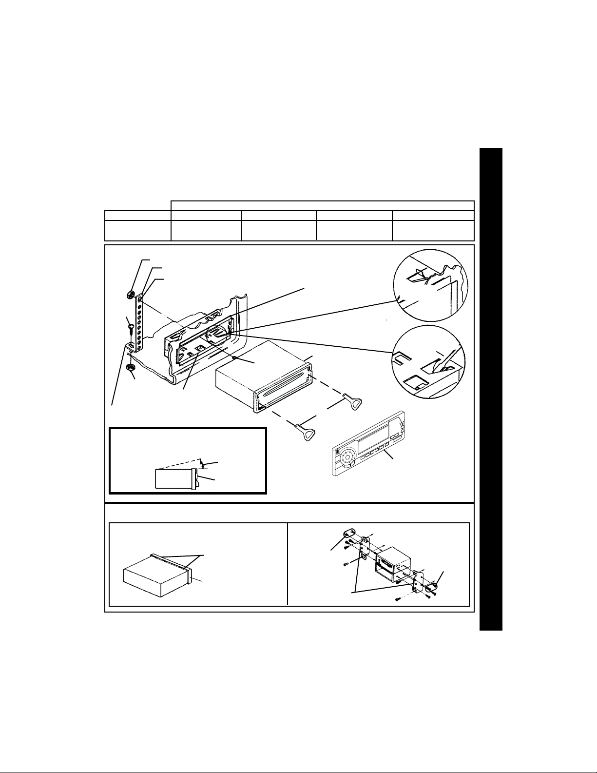
UNIVERSAL INSTALLATION PROCEDURE USING MOUNTING SLEEVE
1. Remove the detachable front panel if it is attached to the chassis by pushing the “Release” button. Slide the mounting sleeve off of the chassis. If it is locked into position, use the removal tools (supplied) to disengage it.
2. Check the dashboard opening size by sliding the mounting sleeve into it. If the opening is not large enough,carefully
cut or file as necessary until the sleeve easily slides into the opening. Do not force the sleeve into the opening or cause it to bend or bow. Check that there will be sufficient space behind the dashboard for the radio chassis.
ION INSTRUCION INSTRUC
ION INSTRUCION INSTRUC
ION INSTRUC
TT
TT
T
3. Locate the series of bend tabs along the top, bottom, and sides of the mounting sleeve. With the sleeve fully
AA
AA
A
inserted into the dashboard opening, bend as many of the tabs outward as necessary so that the sleeve is
firmly secured to the dashboard.
ALLALL
ALLALL
ALL
4. Place the radio in front of the dashboard opening so that the wiring can be brought through the mounting sleeve.
Follow the wiring diagram carefully and make certain all connections of the wiring harness are secure and
insulated with wire nuts or electrical tape to insure proper operation of the unit. After completing the wiring
INSTINST
INSTINST
INST
connections, attach the front panel and turn the unit on to confirm operation (ignition switch must be “on”).
If unit does not operate, recheck all wiring until problem is corrected. Once proper operation is achieved, turn
off the ignition switch and proceed with final mounting of the chassis.
5. Carefully slide the radio into the mounting sleeve making sure it is right-side-up until it is fully seated and the
spring clips lock it into place.
6. Attach one end of the perforated support strap (supplied) to the screw stud on the rear of the chassis using
the hex nut provided. Fasten the other end of the perforated strap to a secure part of the dashboard either
above or below the radio using the screw and hex nut provided. Bend the strap to position it as necessary.
CAUTION: The rear of the radio must be supported with the strap to prevent damage to the dashboard from
7. Re-attach the front panel to the chassis and test radio operation by referring to the Operating Instructions for
the unit.
INSTALLATION USING KITS
1. If your vehicle requires the use of an installation kit to mount this radio, follow the instructions included with
the installation kit to attach the radio to the mounting plate supplied with the kit.
2. Wire and test the radio as described in Step 4 above.
3. Install the radio/mounting plate assembly to the sub-dashboard according to the instructions of the installation kit.
4. Attach the support strap to the radio and dashboard as described in Step 6 above.
5. Replace the dashboard trim panel.
ISO INSTALLATION PROCEDURE
This unit has threaded holes in the chassis side panels which may be used with the original factory mounting brackets
of some Toyota, Nissan, Mitsubishi, Isuzu, Hyundai and Honda vehicles to mount the radio to the dashboard. Please
consult with your local car stereo specialist shop for assistance on this type of installation.
1. Remove the existing factory radio from its dashboard or center console mounting. Save all hardware and brackets
as they will be used to mount the new radio.
2. Carefully unsnap the plastic frame from the front of the new radio chassis. Remove and discard the frame.
3. Remove the factory mounting brackets and hardware from the existing radio and attach them to the new radio.
CAUTION : DO NOT EXCEED M5 X 8 MM MAXIMUM SCREW SIZE. LONGER SCREWS MAY TOUCH AND DAMAGE
22
2
22
4. Wire the new radio to the vehicle as per step 4 above.
5. Mount the new radio assembly to the dashboard or center console using the reverse procedure of step 1.
the weight of the radio or improper operation due to vibration.
COMPONENTS INSIDE THE CHASSIS.
INSTALLATION INSTRUCTIONSINSTALLATION INSTRUCTIONS
Page 3
TOLL-FREE INSTALLATION ASSISTANCETOLL-FREE INSTALLATION ASSISTANCE
TOLL-FREE INSTALLATION ASSISTANCE
The installation and wiring connections for this unit are so simple, we doubt you'll need our help, but, if you
do, we're here to help you. Just call our toll-free telephone assistance line at 1-800-645-4994 during the days
and hours shown (U.S.A. and Canada only).
DAY
MON. - FRI.
SATURDAY
NUT (5MM)
PERFORATED STRAP
FASTEN THIS END TO SCREW
STUD ON REAR OF CHASSIS
SCREW
(5MM)
NUT (5MM)
MOUNTING SLEEVE
FASTEN THIS END TO SECURE PART OF DASHBOARD.
DRILL HOLE IF NECESSARY.
TOLL-FREE INSTALLATION ASSISTANCETOLL-FREE INSTALLATION ASSISTANCE
PACIFIC
5:30AM - 4PM
6AM - 2PM
UNIVERSAL INSTALLATION USING MOUNTING SLEEVEUNIVERSAL INSTALLATION USING MOUNTING SLEEVE
UNIVERSAL INSTALLATION USING MOUNTING SLEEVE
UNIVERSAL INSTALLATION USING MOUNTING SLEEVEUNIVERSAL INSTALLATION USING MOUNTING SLEEVE
MOUNTAIN
6:30AM - 5PM
7AM - 3PM
EXISTING DASH OPENING
FILE EDGES TO FIT IF NECESSARY - DO NOT OVERFILE
NOTE: IF DASH IS SOLID, USE REAR SIDE (WITHOUT THE LIP) OF
MOUNTING SLEEVE AS A TEMPLATE & CUT OPENING
SCREW STUD
TIME ZONE
REMOVAL TOOLS
CENTRAL EASTERN
7:30AM - 6PM
8AM - 4PM
RADIO
8:30AM - 7PM
9AM - 5PM
BEND TOP
TABS UPWARD
BEND BOTTOM
TABS DOWNWARD
INST
INSTINST
INSTINST
ALL
ALLALL
ALLALL
A
AA
AA
T
TT
TT
ION INSTRUC
ION INSTRUCION INSTRUC
ION INSTRUCION INSTRUC
T
TT
TT
IONS
IONSIONS
IONSIONS
FOR PROPER OPERATION OF THE CD PLAYER, THE CHASSIS
MUST BE MOUNTED WITHIN 20° OF HORIZONTAL. MAKE SURE
THE UNIT IS MOUNTED WITHIN THIS LIMITATION.
SIDE VIEW
OF
CHASSIS
REMOVE THE PLASTIC FRAME FROM THE FRONT OF
THE CHASSIS BY CAREFULLY UNSNAPPING IT.
CAUTION:
20° MAX.
FRONT PANEL
ISO INSTALLATIONISO INSTALLATION
ISO INSTALLATION
ISO INSTALLATIONISO INSTALLATION
UNSNAP AT 2 PLACES
EACH ON TOP AND BOTTOM
PLASTIC FRAME
MAXIMUM
SCREW SIZE
M5 x 8
FACTORY MOUNTING
BRACKETS
FOLD-DOWN
DETACHABLE
FRONT PANEL
TYPICAL INSTALLATION
MAXIMUM
SCREW SIZE
M5 x 8
33
3
33
Page 4
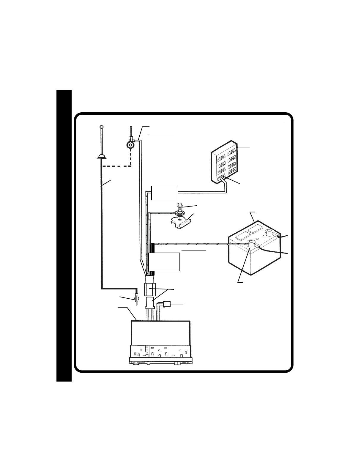
RADIO WIRINGRADIO WIRING
RADIO WIRING
RADIO WIRINGRADIO WIRING
REFER TO PAGE 5 FOR SPEAKER WIRING
ANTENNA
DIO WIRINGDIO WIRING
DIO WIRINGDIO WIRING
DIO WIRING
AA
AA
A
RR
RR
R
ANTENNA
PLUG
ANTENNA
CONNECTOR
AUTOMATIC
ANTENNA
EXISTING
ANTENNA
CABLE
BLUE
IMPORTANT
THE BLUE WIRE CAN BE
USED TO REMOTELY ACTIVATE AN AUTOMATIC ANTENNA OR AN EXTERNAL
AMPLIFIER (SEE ANTENNA
OR AMPLIFIER MANUAL)
1-AMP FUSE
BLACK
YELLOW
FILTER/FUSE
BOX
15-AMP FUSE
RED
SCREW
METAL PART OF DASH
(DRILL HOLE IF NECESSARY)
IMPORTANT
YELLOW WIRE MUST BE
CONNECTED AS SHOWN OR
RADIO WILL NOT OPERATE
PROPERLY
4 PIN PLUGS
9 PIN PLUG
(SEE PAGE 5 FOR SPEAKER
WIRING)
FUSEBLOCK
“RADIO” FUSE
+ 12V ACCESSORY
CAR BATTERY
POSITIVE (+)
TERMINAL 12V
BATTERY
44
4
44
RADIO
Page 5

SPEAKER WIRINGSPEAKER WIRING
SPEAKER WIRING
SPEAKER WIRINGSPEAKER WIRING
REFER TO PAGE 4
FOR RADIO WIRING
RCA LINE IN
JACKS
FOR USE WITH
AUXILIARY INPUT
DEVICES (CD
PLAYER, ETC.)
RCA LINE OUT
JACKS
FOR USE WITH
OPTIONAL
EXTERNAL
AMPLIFIERS
WARNING!
! THE AMPLIFIERS IN THIS RADIO ARE ONLY DESIGNED FOR USE WITH 4 SPEAKERS.
!
NEVER COMBINE (BRIDGE) OUTPUTS FOR USE WITH 2 SPEAKERS.
!
NEVER GROUND NEGATIVE SPEAKER LEADS TO CHASSIS GROUND.
! FAILURE TO WIRE EXACTLY AS SHOWN BELOW MAY CAUSE ELECTRICAL
DAMAGE TO THE RADIO.
RADIO
NOTE:
CALL 1-800-645-4994 FOR RECOMMENDATIONS
OF MODEL CHANGERS THAT WILL WORK WITH
YOUR RADIO.
DIN CABLE (SUPPLIED
WITH CD CHANGER).
OPTIONAL CD CHANGER
6
COMPACT
SPE
SPESPE
SPESPE
A
AA
AA
K
KK
KK
ER WIRING
ER WIRINGER WIRING
ER WIRINGER WIRING
BLK
GRN
LEFT FRONT SPEAKER
WHITE = LEFT
RED = RIGHT
RCA LINE OUT
JACK TO
OPTIONAL
SUBWOOFER
SPEAKER
LEFT REAR SPEAKER
GREY
9-PIN PLUGS
WHITE w/BLACK STRIPE
WHITE
GREEN
GREEN w/BLACK STRIPE
Monday - Friday
Saturday
1-800-645-49941-800-645-4994
1-800-645-4994
1-800-645-49941-800-645-4994
8-PIN DIN SOCKET FOR CONNECTION TO
OPTIONAL CD CHANGER
SEE PAGE 4 FOR
RADIO WIRING
GRAY w/BLACK STRIPE
VIOLET w/BLACK STRIPE
HELP!
8:30am - 7:00pm Eastern
9:00am - 5:00pm Eastern
4-PIN PLUGS
GRAY
VIOLET
RIGHT FRONT SPEAKER
RIGHT REAR SPEAKER
55
5
55
Page 6
OPEROPER
OPER
OPEROPER
AA
TT
ING INSTRUCING INSTRUC
A
T
ING INSTRUC
AA
TT
ING INSTRUCING INSTRUC
TT
IONSIONS
T
IONS
TT
IONSIONS
IONSIONS
IONSIONS
IONS
TT
TT
T
ING INSTRUCING INSTRUC
ING INSTRUCING INSTRUC
ING INSTRUC
TT
TT
T
AA
AA
A
OPEROPER
OPEROPER
OPER
11
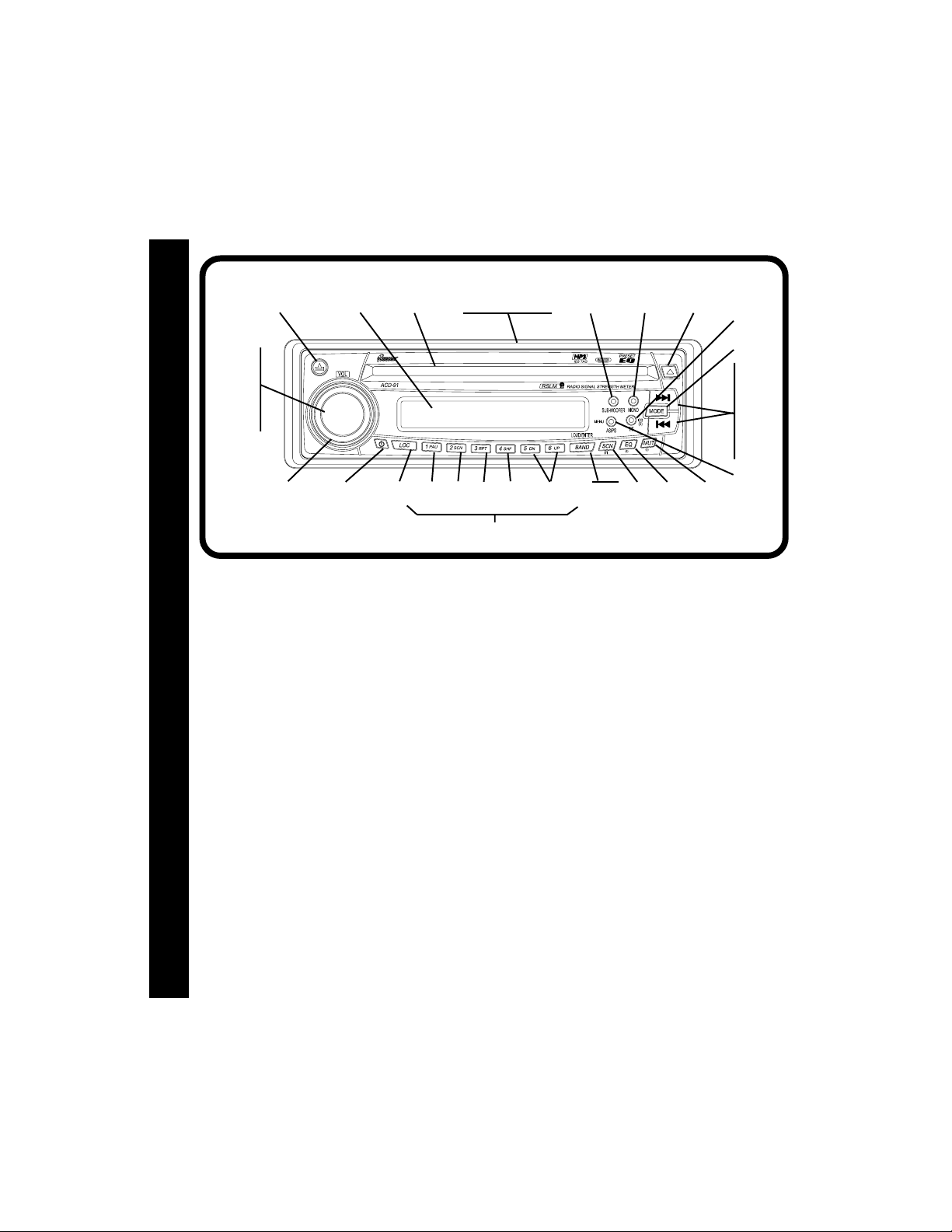
1 ON-OFF POWER BUTTON
11
Press this button to turn the unit on and off
when the ignition switch is on. When the unit
is off, the Liquid Crystal Display (LCD) panel
will normally display the time-of-day. If the
radio is off when the ignition switch is turned
off, the POWER button must be pressed to
turn on the radio after the ignition switch is
turned on. If the ignition switch is turned off
while the radio is on, the radio will display
the time of day, and will come on
automatically when the ignition switch is
again turned on.
22
2 VOLUME LEVEL CONTROL
22
To increase the volume level, rotate the
PUSH SELECT-VOL control clockwise (CW).
The volume will increase and the level will be
shown on the display panel from a minimum
of 00 to a maximum of 100. To decrease the
volume level, rotate the PUSH SELECT-VOL
control counterclockwise (CCW). The volume will decrease as shown on the display
panel. This control also includes the inte-
6
gral Select button
34
3
4
5
6
7
2
1
3 for adjustment of the
2019
CAR CD MP3 PLAYER RECEIVER
13 27
35
32, 33
BEHIND PANEL
2339244025
41
16
bass, treble, balance and fader levels as de-
scribed in 4, 5, 6, and 7.
33
3 PUSH SELECT BUTTON (SEL)
33
This button is used to select the audio function
(bass, treble, balance, or fade) to be adjusted
using the Volume Level control
Select button once will set the unit for volume
adjustment (VOL will appear on the display panel).
Pressing the button additional times will select
bass adjustment (BAS on display), treble (TRB),
balance (BAL), or fader (FAD). The display will
automatically return to the normal indication 5
seconds after the last adjustment or when another
function is activated.
NOTE: If the BAS or TRB functions are set while
44
4 BASS CONTROL
44
To adjust the bass level, first select the Bass
mode by pressing the PUSH SELECT button 3
so the BAS indication appears on the display
panel. Within 5 seconds of choosing the Bass
30 14
SUB
26
36
the Equalizer function (PEQ) is active, the
Equalizer function will automatically revert
to the FLAT setting.
8, 10 9
28
1718
2. Pressing the
31
29
11
12
21
22
37
38
15
Page 7

mode, rotate the Volume Level control 2 CCW or
CW to adjust the bass response as desired. The
level will be shown on the display panel from a
minimum --10 to a maximum of 10 (00 indicates
flat response). The display will automatically return
to the normal indication 5 seconds after the last
adjustment or when another function is activated.
55
TREBLE CONTROL
5
55
To adjust the treble level, first select the Treble
mode by pressing the PUSH SELECT button
the TRB indication appears on the display panel.
Within 5 seconds of choosing the Treble mode,
rotate the Volume Level control 2 CCW or CW to
adjust the treble response as desired. The level
will be shown on the display panel from a minimum
of --10 to a maximum of 10 (00 indicates flat
response). The display will automatically return to
the normal indication 5 seconds after the last
adjustment or when another function is activated.
66
6 LEFT/RIGHT BALANCE CONTROL
66
To adjust the left-right speaker balance, first select
the Balance mode by pressing the PUSH SELECT
3 so the BAL indication appears on the
button
display panel. Within 5 seconds of choosing the
Balance mode, rotate the Volume Level control 2
CCW to adjust the stereo balance to the left channel
speakers, or CW to adjust it to the right channel
speakers. The balance position will be shown on
the display panel from BAL 10L (full left) to BAL 10R
(full right). When the volume level between the left
and right speakers is equal, BAL L=R will be
shown on the display panel. The display will
automatically return to the normal indication 5
seconds after the last adjustment or when another
function is activated.
77
7 FRONT/REAR FADER CONTROL
77
To adjust the front-rear speaker balance, first select
the Fader mode by pressing the PUSH SELECT
3 so the FAD indication appears on the
button
display panel. Within 5 seconds of choosing the
Fader mode, rotate the Volume Level control 2
CCW or CW to adjust the front-rear speaker balance
as desired. The fader position will be shown on
3 so
the display panel from FAD 10R (full rear) to
FAD 10F (full front). When the level between
the front and rear speakers is equal, FAD F=R
will be shown on the display panel. The display
will automatically return to the normal
indication 5 seconds after the last adjustment
or when another function is activated.
88
8 LOUDNESS CONTOUR (
88
ENTER)
When listening to music at low volume levels,
this feature will boost the bass and treble
ranges to compensate for the characteristics
of human hearing. Press the
button for 2 seconds to activate this feature
and the indication LOUD ON will appear on the
display panel for 5 seconds. Pressing the
button again for 2 seconds will deactivate the
feature, and LOUD OFF will appear on the
display panel for 5 seconds.
99
9 AUDIO MUTE SELECTOR (MUT)
99
Press this button momentarily to mute the
volume from the system (MUTE will appear
flashing on the display panel). Pressing this
button again, adjusting the Volume Level
2, or pressing any other button, will
control
return to the volume level setting in use before
the Mute function was activated.
blbl
bl AM/FM BAND SELECTOR (
blbl
ENTER)
BAND/
Each time the
pressed, the radio band is changed. The
indications F1, F2, F3 or AM will appear in the
display panel according to your selection.
bmbm
bm AUTOMATIC UP/DOWN TUNING
bmbm
( / )
To select a radio station in the automatic mode,
momentarily press the Up Tuning
button to advance the unit to the next available
station, or the Down Tuning
tune downward to the next available station.
The radio will automatically seek the next
strongest station. If the Local mode (LOCAL)
LOUD/ENTER button is
BAND/
LOUD/
BAND
/LOUD
BAND/
LOUD
( )
( ) button to
OPER
OPEROPER
OPEROPER
A
AA
AA
T
TT
TT
ING INSTRUC
ING INSTRUCING INSTRUC
ING INSTRUCING INSTRUC
T
TT
TT
IONS
IONSIONS
IONSIONS
/
7
Page 8

is active, the radio will seek the next strongest
local station when either button is pressed.
IONSIONS
IONSIONS
IONS
TT
TT
T
bnbn
MANUAL SEEK TUNING
bn
bnbn
This function is used to search rapidly upward
or downward for a desired station. By pressing
either tune button for more than 2 seconds,
the radio will enter the MANUAL seek mode
as displayed momentarily on the panel. When
either button is pressed and held in this
mode, the radio will tune rapidly up or down
ING INSTRUCING INSTRUC
ING INSTRUCING INSTRUC
ING INSTRUC
and will stop at the station of choice when the
TT
TT
T
AA
AA
A
button is released. A momentary press of
either button in this mode will cause the radio
to tune upward or downward two digits at a
OPEROPER
OPEROPER
OPER
time. If tuning is not activated within 5 seconds
of entering the MANUAL mode, the radio will
automatically revert to the default AUTO mode
as indicated momentarily on the panel.
bobo
bo LOCAL/DISTANT SELECTOR (
bobo
This feature is used to select the strength of
the signals at which the radio will stop during
Automatic Up/Down Tuning. Pressing the
button will select the Local setting (LOCAL
will appear on the display panel for 5 seconds)
and tuning will select only strong (local)
stations for reception. Pressing the button
again will select the Distant setting (DX will
appear on the display panel for 5 seconds)
and the tuning will stop at a wider range of
signals, including weaker (more distant)
stations.
bpbp
bp FM MONO SELECTOR (MONO)
bpbp
During FM radio operation, this button is
used to select mono or stereo reception of
the broadcast signal. Under normal reception
conditions, the unit should be left in the
stereo mode as indicated by ST and the
associated signal strength indicator on the
display panel when tuned to an FM stereo
signal. If the stereo signal is too noisy for
comfortable listening, press the MONO button
to switch to mono reception (the ST indication
88
8
88
will disappear from the display panel). To
LOC
return to stereo reception mode, press the button
again; the ST indication is displayed.
bqbq
bq AUTOMATIC STORE/PRESET SCAN
bqbq
(AS/PS)
Press this button momentarily to scan the stations
pre-set into the memories on the 3 FM bands or
the AM band. The unit will stop at each pre-set
station for 5 seconds before continuing to the
next pre-set station (the pre-set number on the
display panel will flash during Pre-Set Scan
operation). Press the button again momentarily
to stop Pre-Set Scan operation and remain on
the selected frequency.
Pressing and holding the button for longer than
2 seconds will activate the Auto-Store Tuning
feature which will automatically scan and enter
up to 6 stations into the 6 pre-set memories on
the band in use. After entering the stations into
the memories, the unit will automatically stop at
)
each station for 5 seconds so each can be
heard. If you have already set the pre-set
memories to your favorite stations, activating the
Auto-Store Tuning feature will erase those
stations and enter the new ones. This feature is
most useful when travelling in a new area where
you are not familiar with the local stations.
brbr
br STATION PRE-SET MEMORIES
brbr
To set any of the 6 pre-set memories in each
band, use the following procedure:
1. Turn the radio on and select the desired
band.
2. Select the first station to be pre-set using the
Automatic Up/Down
Tuning Controls.
3. Press the pre-set button to be set and
continue to hold it in for approximately 2
seconds. The pre-set number will appear
on the display panel indicating that the
station is now set into that pre-set memory
position. The station can now be recalled at
any time by pressing that button.
4. Repeat the above procedure for the
remaining 5 pre-sets on that band and for
the other 3 bands on the unit.
bm, or Manual Seek bn
Page 9

bs bs
bs
EQUALIZER (EQ) BUTTON
bs bs
The EQ button applies preset sound effects to
the unit’s audio output signal.The EQ button,
when pressed, will activate one of the following
operating modes ( CLASSICS, POP M, ROCK M,
DSP OFF or FLAT). If the Equalizer function is
active, as displayed on the panel, and the bass
and/or treble level is set, the Equalizer function
reverts to the FLAT setting. On the other hand, if
the Equalizer function is activated, the bass/
treble setting(s) are ignored. Conversely, when
the Equalizer function is not active, the unit returns
to the user set bass and treble levels.
bt bt
bt STATION SCAN (
bt bt
When this button is pressed during radio
operation, each station in the current band will be
scanned in the upward direction; each displayed
station will flash for 5 seconds before moving on
to the next station. If the local mode is active, only
the stronger, nearby stations in the current band
will be scanned. When the desired station
appears, press the SCN button again to remain
on that frequency.
bubu
bu LIQUID CRYSTAL DISPLAY PANEL
bubu
The Liquid Crystal Display (LCD) panel displays
the frequency, time and activated functions,
including a combination audio level/disc
indicator in the form of dual disc icons (
with circular bar graphs depicting the the audio
signal. In addition, the display also contains a
receive signal indicator which depicts the relative
strength of the incoming broadcast frequency.
NOTE: It is a characteristic of LCD panels that,
if subjected to cold temperatures for an
extended period of time, they may take
longer to illuminate than under normal
conditions. In addition, the visibility of
the numbers on the LCD may slightly
decrease. The LCD read-out will return
to normal when the temperature
Increases to a normal range.
SCN
) BUTTON
clcl
cl DISC SLOT
clcl
Gently insert the disc into the slot (label surface
facing up) until the soft-loading mechanism
engages and pulls the disc in. The S--CDP
indication will appear on the display panel for
5 seconds, the center of the disc
indication illuminates and becomes animated,
and the track number and elapsed time appear
on the display panel.
CAUTION: This unit is designed for play of
standard 5" (12cm) compact
ONLY. Do not attempt to
discs
use 3" (8cm) CD-Singles in this
unit, either with or without an
adapter, as damage to the player
and/or disc can occur. Such
damage will not be covered by the
Warranty on this product.
cmcm
cm TRACK SELECT ( / )
cmcm
The Track Select function of the Tune/Seek/
Track buttons is used to quickly access the
beginning of a particular track when a disc is
in play. Each time the Forward Track Select
) button is pressed, the next higher track
(
number will be selected as shown on the
display panel. Similarly, each time the
Backward Track Select (
)
next lower track number will be selected as
shown on the display panel.
cncn
cn
CUE/REVIEW FUNCTIONS ( / )
cncn
High-speed audible search to any section of
the disc can be made by the Cue and Review
functions. Press and hold the Cue (
to advance rapidly in the forward direction (the
advancing disc playing time will be shown on
the display panel, except for discs formatted
with MP3 audio), or the Review (
advance rapidly in the backward direction (the
decreasing disc playing time will be shown on
the display panel, except for discs formatted
with MP3 audio).
) is pressed, the
( )
) button
) button to
OPER
OPEROPER
OPEROPER
A
AA
AA
T
TT
TT
ING INSTRUC
ING INSTRUCING INSTRUC
ING INSTRUCING INSTRUC
T
TT
TT
IONS
IONSIONS
IONSIONS
9
99
9
99
Page 10

co co
co
TRACK SCAN SELECTOR (
co co
During disc play, press this button to play the
IONSIONS
IONSIONS
IONS
first 10 seconds of each track on the disc
TT
TT
T
(S--SCN will appear on the display panel).
When a desired track is reached, press the
SCN button again to cancel the function
(S--SCN will disappear from the display
panel) and play of the selected track will
continue. Scan mode will also be canceled
by activating the Repeat Play
ING INSTRUCING INSTRUC
ING INSTRUCING INSTRUC
ING INSTRUC
TT
TT
T
AA
AA
A
OPEROPER
OPEROPER
OPER
cq functions.
Play
cpcp
cp REPEAT PLAY SELECTOR (
cpcp
During disc play, press this button to repeat
the play of the selected track (S--RPT will
appear on the display panel). Play of the track
will continue to repeat until the button is
pressed again and the S--RPT indication
disappears from the display panel. Repeat
Play mode will also be canceled by activating
the Track Scan
cqcq
cq SHUFFLE PLAY SELECTOR (
cqcq
During disc play, press this button to play the
tracks on the disc in a random shuffled order
(S--SHF will appear on the display panel). In
Shuffle Play mode, the TRACK Select function
will also select tracks in random order instead
of the normal progression. The Shuffle Play
mode can be canceled by pressing the button
again (S--SHF indication will disappear from the
display panel) or by activating the Repeat Play
co or Shuffle Play cq functions.
cp or Track Scan co functions.
crcr
cr DISC SELECT UP/DOWN (
crcr
These buttons are used to select the desired
disc for play during changer operation. To advance to a higher number disc, press the
button, and to return to a lower number disc,
press the DN button. The number of the disc in
play will be shown on the display panel.
cscs
cs DISC PAUSE (
cscs
When this button is pressed during disc play,
1010
10
1010
S--PAUSE will appear on the display, and
PAU
)
SCN
)
cp, or Shuffle
RPT
)
SHF
)
UP/DN
)
UP
disc play will be suspended; the center of the
disc icon (
pause. When the button is pressed again,
S--PAUSE will disappear from the display and play
will resume from the point at which pause occurred.
ctct
ct DISC EJECT ( )
ctct
Disc play is stopped and the disc is ejected when
this button is pressed. Radio or CD changer
operation will automatically resume depending
on which mode was in operation prior to disc play.
If the disc is not removed from the unit within 15
seconds of being ejected, it will automatically be
re-loaded into the unit to prevent it from being
accidentally damaged (
display panel to indicate that a disc is loaded in the
player). Play of the disc can be resumed by using
the MODE button
function.
cucu
cu MODE SELECTOR (MODE)
cucu
During radio or tape play, press this button to
select operation of the optional CD changer as
shown by CDC, the disc number and the track
number on the display panel. Refer to the CD
Changer Controls section for specific operating
instructions.
If the button is pressed when no CD changer is
connected to the unit, no CDC indications will
appear on the display panel. The unit will then
return to radio operation. To return to the disc play
operation (if a compact disc is loaded in the unit),
press the button again. During disc play, press this
button to change to radio operation without ejecting
the disc.
dl dl
dl SUB-WOOFER SELECT
dl dl
When the SUB-WOOFER button is pressed, the
sub-woofer audio output, via the single RCA
connector, is made available to an optional subwoofer speaker, if installed in the vehicle.
) will stop rotating, indicating disc
will appear on the
cucu
cu to choose the CD player
cucu
Page 11

dmdm
dm
TIME/FREQUENCY (T/F) SELECTOR
dmdm
Pressing the Time/Frequency (T/F) button will
display the time of day for 5 seconds, after which
the display will automatically return to the radio,
tape or CD changer display, depending on which
one was currently active.
To set the correct time of day, refer to the procedure
for Setting the Clock.
dn dn
THEFT-DETERRENT LED
dn
dn dn
Located on the chassis behind the front panel,
a light-emitting diode (LED) will flash when the
panel is removed. The flashing light serves as
a visual warning to the would-be thief that the unit
has been disabled by removal of the front panel.
do do
do RESET BUTTON
do do
A RESET button is located on the front of the
chassis (front panel must be removed to access
the button). The reset circuitry is provided to
protect the microprocessor circuitry and should
only be activated under the following
circumstances as it will erase the time and preset memories.
1. Upon initial installation after all wiring is
completed.
3. If there is a malfunction of any of the switches
on the unit, pressing the RESET button may
clear the system and return to normal
operation.
dpdp
dp FRONT PANEL RELEASE BUTTON
dpdp
This button is used to release the mechanism
that holds the front panel to the chassis. To
detach the front panel, press the button so that
the left side of the panel is released. Grasp the
released side and pull it off of the chassis. To
re-attach the panel, position the right side of the
panel in place first and then press the left side
of the panel until the mechanism locks it into
place.
NOTES ON USE OF FRONT PANEL
1. Make sure the front panel is right-sideup when attaching it to the chassis as it
cannot be attached when up-side down.
2. Do not press very hard on the front panel
when attaching it to the chassis.No more
than light to moderate pressure should
be needed.
3. When attaching the front panel, make
sure the right side is correctly engaged
before pressing the left side to lock it
into position.
4. When taking the front panel with you,
please use the supplied carrying case
to protect the panel from dirt and
damage. Make sure there is no dust or
dirt on the electrical terminals on the
back of the panel as this could cause
intermittent operation or other
malfunctions.
DETACHING THE FRONT PANEL
Release
button
ATTACHING THE FRONT PANEL
Engage right
side first
OPER
OPEROPER
OPEROPER
A
AA
AA
T
TT
TT
ING INSTRUC
ING INSTRUCING INSTRUC
ING INSTRUCING INSTRUC
T
TT
TT
IONS
IONSIONS
IONSIONS
11
Page 12

SETTING THE CLOCK
1. Switch the vehicle ignition and radio on.
OR CODESOR CODES
OR CODESOR CODES
OR CODES
2. Momentarily press the Time/Frequency (T/F) Select button
on the display panel.
3. Press and hold the Time/Frequency button until the time display begins flashing. While
the display is still flashing, press the Up Tuning
the Down Tuning
4. Five seconds after the last hour or minute adjustment is made, the time will be set in the
unit and the display will return to the normal indication.
ING THE CLOCK/CD ERRING THE CLOCK/CD ERR
ING THE CLOCK/CD ERRING THE CLOCK/CD ERR
ING THE CLOCK/CD ERR
TT
TT
T
SETSET
SETSET
SET
( ) button to adjust the minutes to the correct time.
( ) button to adjust the hours and then
dmdm
dm so that the time is shown
dmdm
CD PLAYER ERROR CODES
If a problem should develop while operating the CD player, an error code (ER-1, ER-2,
ER-3, etc.) may appear on the display panel. This can indicate a number of problems
with the unit, including a mechanical error or an error in the microprocessor control of the
player. If an error code should appear, try ejecting and re-loading the disc into the player.
While the disc is out of the unit, make sure it is clean, undamaged, and loaded correctly
(label surface up). You may also try activating the RESET button
will also erase the time and pre-set memories.
If the suggested measures do not solve the problem, contact an approved warranty
station near you for further assistance.
1212
12
1212
dodo
do on the unit, but this
dodo
Page 13

SPECIFICA
SPECIFICASPECIFICA
SPECIFICASPECIFICA
SPECIFICASPECIFICA
SPECIFICA
SPECIFICASPECIFICA
Size: 7” W x 2” H x 6” D
Operating Voltage: 12 volts DC, negative ground
Output Power: 160 watts maximum (40 watts x 4 channels)
Output Wiring: Floating-ground type designed for 4 speaker use.
Output Impedance: Compatible with 4 - 8 ohm speakers
Pre-Amp Output: 500 mv.
Tuning Range: AM: 530 - 1,710 KHz. (10 KHz. step)
Sensitivity: AM: >45 dB.
FM Stereo Separation: 25 dB at 1kHz
CD Frequency Response: 5 – 20 kHz. +0/-3 dB
CD Signal/Noise Ratio: >70 dB
CD Channel Separation: >60 dB
TT
IONSIONS
T
IONS
TT
IONSIONS
178 mm x 50 mm x 150 mm
The amplifiers in this unit are NOT designed for use with
2 speakers.
RCA pre-amp level outputs.
FM: 87.5 - 107.9 MHz. (200 KHz. step)
FM: >15 dB at a S/N of 30 dB
T
TT
TT
IONS
IONSIONS
IONSIONS
CD Distortion: 0.2%
*Specifications are subject to change without notice.
1313
13
1313
Page 14

NOTES ON DISCS:
Attempting to use non-standard shape discs (e.g.; square, star, heart) may damage the unit. Be
sure to use round-shape CDs only in this unit.
NOTES ON CD-Rs (Recordable CDs)/CD-RWs (Rewriteable CDs):
TES ON DISCSTES ON DISCS
TES ON DISCSTES ON DISCS
TES ON DISCS
NONO
NONO
NO
1. Be sure to use discs with the following marks only for play in this unit:
2. The unit cannot play a CD-R or CD-RW that is not finalized. (Please refer to the
manual of your CD-R/CD-RW software for more information on the finalization
process.)
3. Depending on the recording status, conditions of the disc and the equipment used
for the recording, some CD-Rs/CD-RWs may not be played on this unit.
RELIABLE PLAYBACK:
To ensure more reliable playback, please note the following recommendations:
1. Use CD-RWs with speed 1x to 4x.
2. Use CD-Rs with speed 1x to 8x, and write with speed 1x to 2x.
3. Do not play a CD-RW which has been written on more than 5 times.
NOTES ON MULTI-SESSION DISCS:
1. If the first track of the first session is audio CD data, then the unit will play only the
audio CD data.
2. When the first track of the first session in not audio CD data, but an MP3 file, then
only the MP3 files will be played back and other data (including CD data) is skipped.
1414
14
1414
Page 15

CD CHCD CH
CD CH
CD CHCD CH
Built into this radio are controls to operate an
optional CD changer. Please check with your
Rampage/Audiovox car stereo specialist for
recommendations of the models that will work
with this radio.
Once the changer is installed and properly
connected, it may be necessary to press the
RESET button behind the radio front panel to
initialize the complete installation.
Adjustment of the audio functions (volume, tone,
balance, and fader) for the CD changer operate
in the same manner as they do for radio play.
The following controls will operate the CD
changer when it is installed and connected to
this radio. Refer to the owner’s manual included
with the CD changer for instructions on the
installation and correct loading and use of the
CD magazine.
dqdq
dq CD CHANGER PAUSE/PLAY SELECTOR
dqdq
(
During radio, or tape play, press the MODE
button
as shown by CDC on the display. Disc play will
begin, the disc and track number will be shown
on the display panel, and the center of the disc
icon (
magazine has been loaded into the changer,
play will begin from the first track of the first disc
in the magazine. If a magazine was already in
the changer, play will resume from the track on
the disc previously in play.
During CD changer play, pressing the
button once will stop changer play; PAUSE will
appear on the display and the center of the disc
icon will remain stationary. To resume disc
play, press the
will resume from the point at which it was
interrupted.
drdr
dr DISC SELECT (
drdr
These buttons are used to select the desired
disc for play. To advance to a higher number
AA
NGER CONTRNGER CONTR
A
NGER CONTR
AA
NGER CONTRNGER CONTR
PAU
)
cucu
cu to select operation of the CD changer
cucu
) will become animated. If a new
PAU
button again and disc play
UP/DN
OLOL
SS
OL
S
OLOL
SS
PAU
)
disc, press the UP button To return to a lower
number disc, press the
number of the disc in play will be shown on the
display panel.
dsds
ds TRACK SELECT ( / )
dsds
This button is used to quickly select the
beginning of a particular track. With each
momentary press of the Forward Track Select
button (
be selected as shown on the display panel.
Similarly, with each momentary press of the
Backward Track Select button (
lower track number
dtdt
dt FOWARD/REVERSE SEARCH (CUE/
dtdt
REVIEW)
High-speed audible search to any forward or
reverse section of the disc can be made with
this feature. Press and hold the forward (cue)
button (
direction, or press and hold the reverse (review)
button (
(backward) direction. In either case, the center
of the disc icon will rotate faster when search
is active.
dudu
du TRACK SCAN SELECTOR (
dudu
When the
the SCN indication will appear on the display
panel, and the first 10 seconds of each track
on the disc will be played in order. When a
desired track is reached, press the
again and play of the selected track will
continue (SCN will disappear from the display
panel). The Track Scan mode will also be
canceled by activating any other disc function
(Track Select, Repeat or Random).
When the
more than 2 seconds, the disc scan mode is
activated; DSN will appear on the display and
the first 10 seconds of the first track on each
disc will be played in disc order. This mode is
canceled in the same manner as before.
), the next higher track number will
) to advance rapidly in the forward
) to advance rapidly in the reverse
SCN
button is momentarily pressed,
SCN
button is pressed and held for
DN
button. The
), the next
will be selected.
SCN
SCN
)
button
CD CH
CD CHCD CH
CD CHCD CH
A
AA
AA
NGER CONTR
NGER CONTRNGER CONTR
NGER CONTRNGER CONTR
OL
OLOL
OLOL
S
SS
SS
1515
15
1515
Page 16

el el
TRACK REPEAT PLAY SELECTOR
el
el el
(
RPT
)
RPT
When the
pressed, the RPT indication will appear on
the display panel and play of the current track
OR CODESOR CODES
OR CODESOR CODES
OR CODES
will be continually repeated until the Track
Repeat mode is canceled by pressing the
RPT
button again or by activating the Track
Select, Random Play or Scan
When the
S/CD ERRS/CD ERR
S/CD ERRS/CD ERR
S/CD ERR
more than 2 seconds, the disc repeat mode
is activated; DRT will appear on the display
OLOL
OLOL
OL
and the play of the current disc will be
continuously repeated. This mode is
canceled in the same manner as before.
NGER CONTRNGER CONTR
NGER CONTRNGER CONTR
NGER CONTR
AA
AA
A
button is momentarily
functions.
RPT
button is pressed and held for
emem
em SHUFFLE PLAY SELECTOR (
emem
When the
the SHF indication will appear on the display
panel and the tracks on the disc will be played in
a random, shuffled order. The Track Select
buttons
order instead of the normal progression. The
Track Shuffle mode can be canceled by pressing
the
Select, Repeat Play or Scan functions.
When the
more than 2 seconds, the disc shuffle mode is
activated; DSF will appear on the display and the
play of the discs in the magazine will be played
in a random shuffled order. This mode is canceled
in the same manner as before.
SHF
button is momentarily pressed,
dsds
ds
will also select tracks in the shuffled
dsds
SHF
button again or by activating the Track
SHF
button is pressed and held for
SHF
)
CD CHCD CH
CD CH
CD CHCD CH
CD CHCD CH
CD CH
If a problem should develop while operating the CD changer, the following error codes may
appear on the display panel.
ER-1: Indicates that there is no magazine loaded in the CD changer.
ER-2: Indicates a problem with the magazine eject function.
ER-3: Indicates an error in the disc loading function.
ER-4: Indicates an error in the disc un-loading function.
ER-5: Indicates an error in the magazine position.
ER-6: Indicates an error in the laser pick-up position.
ER-7: Indicates an error in the laser focus on the disc.
In any of the above situations, try ejecting the CD magazine from the changer and make sure
the discs are clean, undamaged, and loaded correctly (refer to the Owner’s Manual of the CD
changer). Re-load the magazine and check for proper operation. You may also try activating
the RESET button
If the suggested measures do not solve the problem, contact an approved warranty station near
you for further assistance.
1616
16
1616
dodo
do on the unit, but this will also erase the time and pre-set memories.
dodo
CD CHCD CH
AA
NGER ERRNGER ERR
A
NGER ERR
AA
NGER ERRNGER ERR
OR CODESOR CODES
OR CODES
OR CODESOR CODES
Page 17

PLAYING MP3 MUSIC FILES
MP3 (Moving Picture Experts Group, Layer 3) are digital audio files that are compressed to
about 1/10th the size of a CD recording. As a result, you can compress a CD song that has 50
megabytes of data into an MP3 that has only 4 or 5 megabytes.
The ACD-91 can play MP3s directly from files contained on a CD-R/RW, by using the MP3
buttons on the radio (or an optional Remote Control).
MP3 CONTROLS
The following buttons represent control inputs, characters and/or numbers dedicated to the
access of files on your MP3 CD.
MP3 PL
MP3 PLMP3 PL
MP3 PLMP3 PL
A
AA
AA
YBACK OPER
YBACK OPERYBACK OPER
YBACK OPERYBACK OPER
A
AA
AA
T
TT
TT
ION
IONION
IONION
CAR CD MP3 PLAYER RECEIVER
14
12
1. AS/PS: The AS/PS button, also labeled MENU, is used to search and/or access the Track
Number and Directory/Album title; additional presses will momentarily access the disc
serial number (if applicable), and display the current Directory/Album title. By using this
button, you can quickly jump to a Directory/Album and then navigate within that area to
locate and play a specific song/track.
BAND
2.
3. Preset 1/PAU: During MP3 disc play, pressing this button in conjunction with the MENU
4. Preset 2: This button functions in the same manner as Preset 1, except it represents
/LOUD/ENTER: The
MP3 CD playback purposes; its function permits entry to the desired Directory/Album or
Track after being accessed by the MENU (AS/PS) button.
button, will select track number 1, or a track number containing this numeral. When a
Directory or song title search is being made, this button also represents alphanumerical
characters A, B, C, 1. Pressing the button consecutively scrolls through the characters.
alphanumeric characters D, E, F, 2.
BAND
/LOUD/ENTER button provides the ENTER function for
SUB
2345678
1
11
9
10
13
1717
17
1717
Page 18

5. Preset 3: This button functions in the same manner as Preset 1, except it represents
IONION
IONION
ION
TT
TT
T
AA
AA
A
YBACK OPERYBACK OPER
YBACK OPERYBACK OPER
YBACK OPER
AA
AA
A
MP3 PLMP3 PL
MP3 PLMP3 PL
MP3 PL
alphanumeric characters G, H, I, 3.
6. Preset 4: This button functions in the same manner as Preset 1, except it represents
alphanumeric characters J, K, L, 4.
7. Preset 5: This button functions in the same manner as Preset 1, except it represents
alphanumeric characters M, N, O, 5.
8. Preset 6: This button functions in the same manner as Preset 1, except it represents
alphanumeric characters P, Q, R, 6.
9. MODE: This button functions in the same manner as Preset 1, except it represents
alphanumeric characters S, T, U, 7.
10. TUNE/SEEK (Down): This button functions in the same manner as Preset 1, except it
represents alphanumeric characters V, W, X, 8.
11. TUNE/SEEK (Up): This button functions in the same manner as Preset 1, except it represents alphanumeric characters Y, Z, Space, 9.
12. Select (PUSH SELECT): This button, which is integral to the VOL control, is used in
conjunction with the MENU button and VOL control knob to confirm selection of the
alphanumeric character when choosing a specific Directory/Album and/or song title.
13. Time/Frequency (T/F): This button functions in the same manner as Preset 1, except
it represents symbol/numeric characters _, -, +, 0. This button also provides access to
the ID3 tag, if one exists on the disc.
14. PUSH SELECT-VOL Up/Down: The VOL knob performs the same function as the other
alphanumeric buttons when choosing a specific Directory/Album and/or song title; however, it allows quicker selection and entry of sequential Alphanumeric characters, and is
used in conjunction with the integral PUSH SELECT button which confirms each sellected character before moving on to the next one.
DN
NOTE: The
track steps during normal CD play and when searching for files or directories.
LOADING AN MP3 DISC
As with a normal music CD, when an MP3 disc is initially loaded, S--CDP appears on the
display for 5 seconds. The (
and the track number momentarily appear, followed by the ID Tag, if supported. After these
initial indications, the track number and song name alternately appear, with the song name
scrolling right-to-left across the display.
1818
18
1818
(Preset 5) and UP (Preset 6) buttons also enable track selection in 10-
) indication illuminates and becomes animated, then MP3 T
Page 19

ACCESSING THE ID3 TAG INFORMATION
To access the ID tag, when available, proceed as follows:
1. Press the ID3 (T/F) button until the ID Tag, if supported, is displayed.
NOTE: The ID TAG can specify the Song name, Artist, Album, Year, and/or Comments.
2. If no ID TAG is available, --NO ID3 will appear on the display following Comments.
SEARCHING BY TRACK NUMBER
To search for a desired track directly, proceed as follows:
1. With the MP3 CD in the play mode, press the MENU (AS/PS) button; MP3 T appears on the
display followed by a flashing character position (
combination thereof, to access the appropriate track.
2. If the desired track number consists of two digits or less, the player will wait a few seconds for the ENTER (
will begin searching for the track automatically.
3. When the track is accessed, the track number appears on the display, followed by the
song name.
ALPHANUMERIC SEARCH FOR SONG FILE OR DIRECTORY NAME
To search for a desired directory or song file on the MP3 CD, proceed as follows:
1. With the MP3 CD in play mode, press the MENU button until only a blinking character
position ( ) appears.
2. Then press the desired buttons, or use the PUSH SELECT-VOL control, to enter the
alphanumeric characters of the desired directory or song file name. Up to eight Alphanumeric characters can be entered for search.
NOTE: An alternate search method is provided by rotating the PUSH SELECT-VOL control
when the blinking character position (
rotating the control clockwise to scroll through the alphabet and digits 0 - 9. After
each character is selected, press the PUSH SELECT - VOL button to confirm the
selection. Then the blinking asterisk will move to the next character position to
await the next selection. Up to eight characters can be entered for search in this
manner.
3. Press the ENTER (
NOTE: If the Directory/File is entered incorrectly, or does not exist, NOT FOUND will be
displayed momentarily.
4. Then continue the search within the sub-directory for the song title by using the
buttons, but use the button first.
5. When the title is accessed, press the ENTER button again to begin play of the
selected song.
BAND
/LOUD/ENTER) button to be pressed; otherwise, the player
BAND
/LOUD/ENTER) button to access the song file or sub-directory.
); then press the direct numeric key or
) appears. This is accomplished by
MP3 PL
MP3 PLMP3 PL
MP3 PLMP3 PL
A
AA
AA
YBACK OPER
YBACK OPERYBACK OPER
YBACK OPERYBACK OPER
A
AA
AA
T
TT
TT
ION
IONION
IONION
/
1919
19
1919
99
9
99
Page 20

NAVIGATING FROM A ROOT OR SUB-DIRECTORY
To search for a desired song from a root directory or a sub-directory on the MP3 CD, proceed
NCENCE
NCENCE
NCE
as follows:
1. With the MP3 CD in play mode, press the MENU button until the root name is displayed
INTENAINTENA
INTENAINTENA
INTENA
ND MAND MA
ND MAND MA
ND MA
RE ARE A
RE ARE A
RE A
ION / CAION / CA
ION / CAION / CA
ION / CA
TT
TT
T
AA
AA
A
YBACK OPERYBACK OPER
YBACK OPERYBACK OPER
YBACK OPER
AA
AA
A
MP3 PLMP3 PL
MP3 PLMP3 PL
MP3 PL
for a second and the first sub-directory or file name is displayed.
a. Search within the directory for the song title by using the
first.
b. Select the sub-directory and see if it contains the desired song file.
NOTE: If the MP3 CD does not contain sub-directories, select the song file directly.
c. Once the desired file is displayed, use the ENTER (
select the song file for play.
2. If the selected name is in the directory, go into the selected directory by pressing the
ENTER (
3. Then continue the search within the directory for the song title by using the
buttons, but use the button first.
4. When the song title is accessed, press ENTER again to begin play of the selected song.
NAVIGATING FROM A CURRENT DIRECTORY
To search for a desired song from the current directory on the MP3 CD, proceed as follows:
1. With the MP3 CD in play mode, press the MENU button until the root name is displayed
for a second and the currently playing file name is displayed (selected).
2. If the displayed name is the desired directory or the file in the directory, go into the
selected directory and play the file by pressing the ENTER (
3. Otherwise, continue the search within the directory for the song title by using the
4. When the song title is accessed, press ENTER button again to begin play of the selected
song.
NOTE: The song Up/Down buttons (
BAND
/LOUD/ENTER) button.
/ buttons, but use the button first.
/ ) reflect those on the radio front panel.
/ buttons, but use the
BAND
/LOUD/ENTER) button to
BAND
/LOUD/ENTER) button.
/
CARE AND MAINTENANCE
The radio section of your new sound system does not require any maintenance. We
recommend you keep this manual for reference on the many features found in this unit as well
as how to set the clock. The compact disc player section also requires no routine maintenance,
but proper understanding of its use and handling will help you obtain maximum enjoyment of
2020
20
2020
its capabilities. The following points should be observed:
Page 21

! When cleaning the interior of the vehicle, do not get water or cleaning fluids on the unit.
! The CD player is a precision instrument and will not operate properly in extreme hot or
cold. In case of such conditions, wait until the interior temperature of the vehicle reaches
a normal temperature before using the player.
! If the temperature inside the player gets too hot, a protective circuit will automatically
stop play of the disc. In this case, allow the unit to cool off before operating the player
again.
! Never insert anything other than a 5" (12 cm) compact disc into the player as the
mechanism can be damaged by foreign objects.
! Do not attempt to use 3" (8 cm) CD-Single discs in this unit, either with or without an
adaptor, as damage to the player and/or disc may occur. Such damage will not be
covered by the Warranty on this product.
! When not using the disc player, always remove the compact disc.
! When the vehicle warms up during cold weather or under damp conditions, moisture may
condense on the lens of the disc player. Should this occur, the player will not operate
properly until the moisture has evaporated.
! The unit is designed with a vibration dampening CD mechanism to minimize interruption
of disc play due to normal vibration in a moving vehicle. When driving on very rough roads,
however, occasional sound skips may occur. This will not scratch or damage the disc
and normal play will resume when the rough conditions cease.
HANDLING COMPACT DISCS
Dirt, dust, scratches, and warpage can cause skips in the playback and deterioration of
sound quality. Please follow these guidelines to take care of your compact discs:
CA
CA CA
CA CA
RE A
RE ARE A
RE ARE A
ND MA
ND MAND MA
ND MAND MA
INTENA
INTENAINTENA
INTENAINTENA
NCE
NCENCE
NCENCE
NCENCE
NCENCE
NCE
INTENAINTENA
INTENAINTENA
INTENA
ND MAND MA
ND MAND MA
ND MA
RE ARE A
RE ARE A
RE A
IONS / CAIONS / CA
IONS / CAIONS / CA
IONS / CA
TT
TT
T
SPECIFICASPECIFICA
SPECIFICASPECIFICA
SPECIFICA
! Use only compact discs with the mark:
! Fingerprints, dust, and dirt should be carefully wiped off the disc’s playing surface (shiny
side) with a soft cloth. Wipe in a straight motion from the inside to the outside of the
disc.
! Never use chemicals such as record sprays, household cleaners or thinner to clean
compact discs. Such chemicals can irreparably damage the disc’s surface.
! Discs should be kept in their storage cases when not in use.
! Do not expose discs to direct sunlight, high temperatures or high humidity for extended
periods.
! Do not stick paper, tape, or labels on the disc surfaces nor write on them with any type
of marker.
2121
21
2121
Page 22

2222
22
2222
THIS PAGE LEFT BLANK INTENTIONALLY
Page 23

12 MONTH LIMITED WARRANTY
AUDIOVOX CORPORATION (the Company) warrants to the original retail purchaser of
this product that should this product or any part thereof, under normal use and conditions,
be proven defective in material or workmanship within 12 months from the date of original
purchase, such defect(s) will be repaired or replaced with new or reconditioned product
(at the Company's option) without charge for parts and repair labor.
To obtain repair or replacement within the terms of this Warranty, the product is to be
delivered with proof of warranty coverage (e.g. dated bill of sale), specification of
defect(s), transportation prepaid, to the warranty center at the address shown below.
This Warranty does not extend to the elimination of car static or motor noise, to correction
of antenna problems, to costs incurred for installation, removal, or reinstallation of the
product, or damage to tapes, compact discs, speakers, accessories, or vehicle electrical
systems.
This Warranty does not apply to any product or part thereof which, in the opinion of the
Company, has suffered or been damaged through alteration, improper installation,
mishandling, misuse, neglect, accident, or by removal or defacement of the factory serial
number/bar code label(s). THE EXTENT OF THE COMPANY'S LIABILITY UNDER THIS
WARRANTY IS LIMITED TO THE REPAIR OR REPLACEMENT PROVIDED ABOVE AND,
IN NO EVENT, SHALL THE COMPANY'S LIABILITY EXCEED THE PURCHASE PRICE
PAID BY PURCHASER FOR THE PRODUCT.
This Warranty is in lieu of all other express warranties or liabilities. ANY IMPLIED
WARRANTIES, INCLUDING ANY IMPLIED WARRANTY OF MERCHANTABILITY, SHALL
BE LIMITED TO THE DURATION OF THIS WRITTEN WARRANTY. ANY ACTION FOR
BREACH OF ANY WARRANTY HEREUNDER INCLUDING ANY IMPLIED WARRANTY OF
MERCHANTABILITY MUST BE BROUGHT WITHIN A PERIOD OF 30 MONTHS FROM
DATE OF ORIGINAL PURCHASE. IN NO CASE SHALL THE COMPANY BE LIABLE FOR
ANY CONSEQUENTIAL OR INCIDENTAL DAMAGES FOR BREACH OF THIS OR ANY
OTHER WARRANTY, EXPRESS OR IMPLIED, WHATSOEVER. No person or representative
is authorized to assume for the Company any liability other than expressed herein in
connection with the sale of this product.
Some states do not allow limitations on how long an implied warranty lasts or the
exclusion or limitation of incidental or consequential damage so the above limitations
or exclusions may not apply to you. This Warranty gives you specific legal rights and you
may also have other rights which vary from state to state.
W
WW
WW
A
AA
AA
RR
RRRR
RRRR
A
AA
AA
NT
NTNT
NTNT
Y
YY
YY
U.S.A.: AUDIOVOX CORPORATION, 150 MARCUS BLVD., HAUPPAUGE, NY 11788 !1-800-645-4994
CANADA: CALL 1-800-645-4994 FOR LOCATION OF WARRANTY STATION SERVING YOUR AREA
128-4270E
2323
23
2323
Page 24

2424
24
2424
© 2003 Audiovox Electronics Corp., Hauppauge, NY 11788
Printed in China
128-6635
 Loading...