


hy-gain
Starkville, MS 39759 USA
INSTRUCTION MANUAL
GENERAL DESCRIPTION
house or another pro
tected location.
D. Mounting Hardware Pack E.
their compatibility. In gen
eral, these will be:
(see CAU
TIONS):
(see Section V).
commu
nications equipment.
F. Ground Hardware.
Ph. (662) 323-9538 FAX: (662) 323-6551
Antenna Rotator CD-451I
has 110 VAC Controller CD45IIX has 220 VAC Controller
The CD-45-II Rotator consists of a bell-type rotator,
a metered control unit and the necessary mounting
hardware. The rotator is designed to mount on a
plate inside a tower or on a mast. The rotator unit
must be wired to the control unit with a 7 or 8 wire
cable. The control unit must be placed inside the
The CD-45-II now features a NEW 8 pin connector
on the rear panel of the control unit for easy
connection to your cable.
Included with this product are the following:
A. Instruction Manual
B. Rotator Unit
C. Controller Unit
Due to the wide variety of towers available, each
installation will have different requirements. The
gauge of the cable to connect the control unit to the
rotator depends upon the distance between the
rotator and control. The longer the distance, the
larger the diameter of the wire required. Various
antennas or beams require different installation
methods. For this reason, the owner must procure
the remainder of the ,components after checking
A. The beam or antenna desired and a suitable
B. A tower or other mechanism to position the
rotator and beam for safe and effective rotation
C. 7-wire cable to connect the control to the rotator
D. Coaxial cable to connect the beam to the
E. Appropriate guy wires as required.
Figure 1
• Metal towers or other position mechanisms must be platted so that if they fracture or blow over in
SPECIFICATIONS
Input Voltage 120 VAC 50/60 Hz
Optional 220 VAC 50/60 Hz
Motor 24 VAC, 2.25 Amp, split phase
Power Transformer 120 VAC/26 VAC
10% duty, thermal switch protected
Optional 220 VAC/26 VAC
10% duty, thermal switch protected
Meter Transformer 120 VAC/23 VAC
Optional 220 VAC/23 VAC continuous duty
Meter DC Voltmeter 1000 ohms/volts
1 MA full scale
Meter Scale Direct Reading:
North centered, 5 degree increments
Optional Direct Reading:
South centered, 5 degree increments
Maxumim Antenna Size:
A. Tower mounted as per Figure 3 8.5 square feet (.79 sq. m) of wind surface area
B. Outside tower or mast mounted as per Fig. 5 or 7 5.0 square feet (.46 sq. m) of wind surface area
Operational Temperature Range -30 degrees to 210 degrees F (-34 to 99 degrees Celsius)
Maximum Interconnect Cable Resistance:
A. Terminal 1 1.0 ohms
B. Terminals 3, 4, 5, 6, 7, 8 2.5 ohms
Rotation Time 45-60 seconds with 60 Hz input
Brake Automatic Disc Type
Rotator Size 8 inches (20 cm)
Maximum diameter by 17 3/8 inches (44 cm) high
Maximum Antenna Mast Size 2 1/16” O.D. (52 mm)
Mounting Hardware Plated Steel Hardware and Plated Steel Clamps
Control Unit Size 8.5 inches (21.6 cm) wide by 9.0 inches (22.8 cm) deep
Shipping Volume 2411.02 cubic inches (0.0395 cu. M)
Shipping Weight 22.0 pounds (9.98kg)
• Towers, often the highest metal parts in the vicinity, require extreme caution during erection and
placement. Extreme care must be taken during erection so that metal towers and beams do not
contact power lines even if the beams slip or rotate, towers fall or fracture or metal wires blow in
high winds, they cannot contact power lines, be a hazard to individuals, or endanger property.
• When not mounted within a tower with a thrust bearing as shown in Figure 4, the rotutor must be
DEBATED.

• Metal towers must be grounded properly at the tower location before the tower Is erected.
This
prong type (grounded back to the service entrance).
and best commercially available components.
resist high wind loads.
Pres
sure").
but the installation is simpler.
support is required for this installation.
and check out its operation prior to installation.
is
to minimize electrical hazard and the possibility
bare aluminum
wires
or stakes in the ground. Use copper ground stakes. The service
of
lightning damage. Do not bury
entrance ground should be checked. The household convenience outlet should be the 3-
• The Control Box is not weatherproof and must be located in the house, ham shack or other
protected location.
The CD-45II Rotator has been carefully designed and manufactured to give many years of
trouble-free service when carefully and professionally installed. It consists of the strongest
TYPES OF INSTALLATIONS
There are three general types of installation (see Figures 4, 6, and 7).
1. The recommended installation is an "Inside"
Tower Mount, as shown in Figure 4, with a top
bushing or bearing to provide lateral support and
When the rotator is properly mounted this way, it
can be rotated to turn an antenna or beam of 8.5
square feet wind surface area. The wind loading
during storms, the rotational inertia of the beam,
and unbalanced weight are more important than
the dead weight of the beam. It is important to
minimize the height of the beam above the rotator
to minimize the overturning force induced in a
high wind ( see "Unbalanced Weight" and "Wind
2. An "Outside" Tower Mount, as per Figure 7, is the
best type of installation when not using an inside
tower mount. The rotator is not as well protected
3. A telescoping or other type mast, as shown in
Figure 6, can also be used. The lower mast
There are variations of mounting, generally into one
of the above categories. For example, the rotator may
be mounted lower in the tower than shown in Figure
4. In that case, more than one bushing or thrust
bearing for the beam mast may be required and
longer coast down time allowed in operation. These
factors are interrelated and the components must be
matched together.
UNBALANCED WEIGHT AND WIND
PRESSUR
1. Unbalanced Weight: Weight should be as closely
balanced as possible. Unbalanced wight creates a
bending moment of force which is concentrated
on the mast at the point where it is clamped to
the rotator.
This moment tends to strain the mast at that
point and also to bind the ball bearings by
creating excessive downward pressure on one
side and upward pressure on the other. Such
unbalance places additional stress on the motor
and gear train. Unbalanced weight becomes
critical as the distance from the antenna boom to
the clamping point at the rotator is increased.
2. Wind Pressure: Wind pressure against the boom
and elements produces a bending force on the
mast which can cause the same stresses as
unbalanced weight. To strengthen the installation
to withstand unbalanced weight and pressure the
top mast should be as short and as strong as
possible. In multiple arrays the heaviest should be
closest to the rotator. In order to distribute the
bending stress and prevent fracture of the mast,
the CD-45-1I Rotator includes two specially
designed steel clamps to secure the mast to the
rotator.
After procuring the type of tower or other
positioning mechanism of the owner's choice, the
next step is to wire the rotator to the control box

WIRING AND CHECK-OUT
the control unit when done.
A preliminary operation check should be made prior
to installation. We recommend the following
NOTE: The CD-45-1I requires only 7 wires to
operate properly since Terminal 2 in the rotator is
unterminated. However, if an 8-wire cable is used,
the Ham IV rotator can be installed at a later time
without changing the cable or control.
C. With the Control Unit and Rotator on the work
table, connect the cable between the Rotator
and Control Unit using the full length ofcable
that will be used in the installation. It is
important that Terminal #I on the Rotator is
connected to Terminal #1 on the Control Unit
and so on. Attach and solder the ends
cable to the 8 pin connector supplied in the
connector parts pack Plug this connector into
of
the
If the Hy-Gain Ham IV is required, due to a larger
antenna being installed, it will only be necessary to
purchase the Ham 1V Rotator, Part Number
5137201. The control units and cable requirements
are identical, therefore, only the installation of the
heavier duty rotator will be necessary.
A. Decide the wire gauge (size) required and obtain
the number of feet of the proper cable (see Table 1).
B. Strip and tin 3/8" on each wire end after removing
about 4 inches of the jacket from one end of
cable. Tinning can be accomplished, after
twisting the strands together, with an ordinary
soldering iron and radio solder, being careful not
to melt the insulation. On the end to be
connected to the control unit, strip the jacket
about 2 inches and strip the insulation from each
wire end 3/8".
NOTE: The specifications call for heavier gauge
wire on Terminal #1. Lead #1 must be heavier
gauge and less total lead resistance (see
Specifications, page 2). Wire the control to the
rotator as shown in Figure 3.
CAUTION
Shorts between terminals or grounded leads may
damage the rotator.
Figure 2 Rotator Wiring
(control)
Figure 3 Rotator Wiring
(Base)

D. Install four 1/4"-20x 11/4" bolts in the four
them as close to equal length as possible.
on which unit you have.
CAUTION
procedure:
illuminated.
drilled or cut to clear the control cable.
I. Return the rotator to full CW position.
terminals, an
d pins of the plug.
mounting holes in the bottom of the bell
housing. Run them in about a 1/2" and leave
E. With the rotator sitting in the upright position,
resting on the four 1/4"-20 x 1 1/4" bolt heads
and connected to the control unit by the cable,
plug the power cord into a 120 VAC 50/60 Hz
or 220 VAC 50/60 Hz wall socket, depending
MOUNTING INSIDE THE TOWER
The rotator is designed for vertical, operation
with the bell shaped housing in the up position.
Water and other contamination will get into the
motor unit
angle, or upside down.
The rotator is mounted inside a tower (see Figure 3)
to the flat tower plate by means of four bolts
furnished in the hardware kit. Use the following
if
it is mounted horizontally, at any
F. Turn the power switch on. The meter should be
G. Depress the "Brake Release" (Center) lever, hold
it, and simultaneously depress the CCW
direction switch (left). The rotator should turn
CCW (looking from the top). This is S-E-N-WS: Release the CCW direction switch; the
rotator will coast down and stop. Now release
the brake switch. The rotator is now locked into
position.
H. Repeat Step G for CW direction by depressing
the brake switch first, then the CW direction
switch (Right).
CAUTION
It is best to release the direction switch just prior
to the end of rotation (extreme CW or CCW
position) in order not to cause undue stress on
the stop arm and/or the gears.
1. Locate the rotator in the tower directly under the
bushing. Note that the tower plate must be cut out
to allow the connecting cable to pass through the
plate
2. Reattach the wires in the same manner as used in
the trial assembly and secure the wires to the
tower in such a manner that the wires will not be
strained.
3. The rotator is attached to the tower plate by
means of fourbolts and lockwashers (see Figure
3). Spacer washers must be used between the
rotator and plate for clearance of the rotator
housing bolt heads. The flat tower plate must be
drilled in four places using the template
provided with this manual unless the tower plate
is already properly drilled. A fifth hole must be
4. Tighten the four bolts, but not to final tightness.
Observe how the rotator turns. It must rotate in
such a manner as to turn the mast concentrically
to the top bushing.
FOR CUSTOMER'S USE ,
Enter the number/color of each lead connected to the
1 2 3 4
5 6 7 8
5. Trial assemble the mast to the top of the rotator
using the U-bolts, nuts and lockwashers through
the rotator and clamps as shown in Figure 3. The
maximum mast diameter that may be used is 2
1/16" O.D.. We recommend 1 1/2" nominal steel
pipe with 1/9" O.D. in standard wall thickness
of .145". For stacked arrays or very large beams,
we recommend extra heavy-duty wall
thickness.200". Both steel pipes can be
purchased to specification ASTM-120.
On any inside tower installation, care must be
exercised to get the antenna mast shimmed to the
exact rotational center of the rotator. The
geometry is such that a mast of 2.062" (21/16")
(52 mm) O.D. pipe will be exactly centered. If
the O.D. of your mast is less than this, you
should shim out to these dimensions.

6. I f
top bushing or bearing.
100 inch
-
pounds of torque.
U-bolt 4
59 Lockwasher, split, l/4"
1
the rotator, top bushing and mast are properly
aligned, there should be unrestricted rotation
through
be moved slightly on the flat plate.
quality bearing is used in the top
36 0 ° . I f
not, the rotator may have to
If
of
(recommended), the shimming procedure must
be done more carefully as closer tolerances are
required. It is important that the rotator does
not try to turn the mast eccentrically with the
a high
the tower
7. Tighten the four bolts carefully-to approximately
8.
Return the rotator to the full CW "S" position.
Mount the beam pointing South. The coaxial
cable should be looped in such a manner that it
will not foul or tangle when the beam turns
around in a circle to the full
36 00
counterclockwise position. (The antenna rotates
"S" to "F' [counterclockwise] on the first turn,
therefore slack should wrap counterclockwise
around the mast.) Tighten the U-bolts securely.
Item
No.
51
52
53
54
55
56
57
Screw, Pan head,
Bolt, 1/4 Clamp 4
Flat washer 4
Grommet 1
Terminal cover 1
58 Nut, 1/4" -
Description
6- 3 2 x 3/ 8 "
20 x
1 1/4" 4
20
Qt
y
2
8
Figure 4
Rotator Mounted Inside Tower
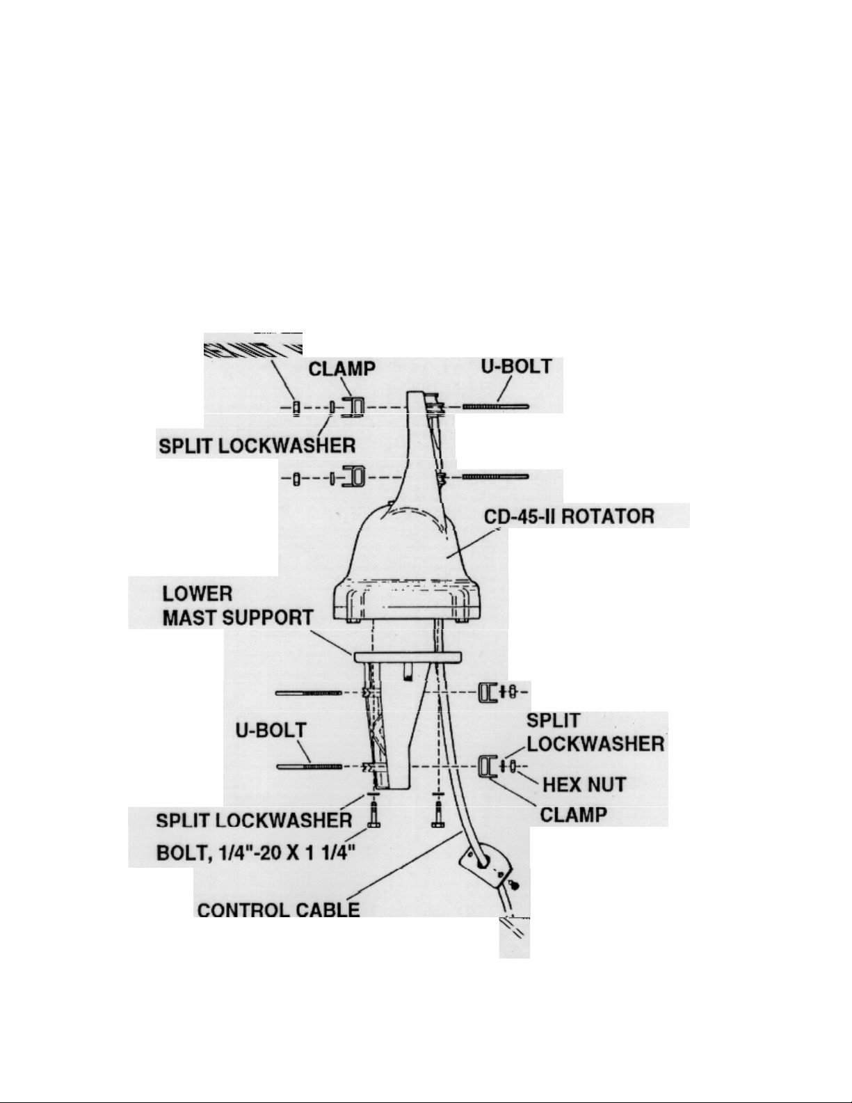
MAST MOUNTING
the mast. (See Figures 5 & 6.)
it to the terminals on the rotator. (See Figure 4.)
18" to 24" apart.
1. Mount the rotator to the lower mast support and to
2. Attach one end of the control cable to the rotator
terminals. Use the same sequence as used on the
pre-installation check. The cover and grommet
must be slipped over the cable prior to attaching
3. Tape the rotator control cable to the mast at points
4. Connect the antenna cable to the antenna (follow
manufacturer's recommendation). Make sure
you have enough slack for the 360° rotation.
(The antenna rotates "S" to "E"
[counterclockwise] during its first turn,
therefore, slack should wrap counterclockwise
around the mast.) See Figure 6.
5. Attach the mast guy wires to the rotator lower
mast support or mast ring
Rotator Mounting with Lower Mast Support
Figure 5
 Loading...