

Page 1

INSTRUCTION MANUAL
y
Downloaded by
RadioAmateur.EU
CAUTION: Read all of the
IMPORTANT SAFEGUARDS contained
elsewhere in this booklet, as
well as all
safety, installation and operating
I instructions supplied with this
unit, and with your antenna, before
installing or operating. Retain
this booklet and all instructions
for your safety and future
reference.
DESCRIPTION
The rotator is designed to turn and accurately position even the
largest TV antenna, assuring the best possible TV picture reception.
Rotation of the drive unit is synchronized with the position of the
moving dot of the control unit. This is accomplished by use of
highly accurate synchronous motors.
The connecting cable between the control unit and the drive unit
carries onl
activated by turning the control knob.
OPERATING & INSTALLATION INSTRUCTION NOTE:
Before mounting drive unit on the support
mast, connect drive unit to control unit
with the control cable and perform the
function shown in paragraph 7.
Step. 1:
safe, low voltage power. When the operating cycle is
DRIVE UNIT MOUNTING
If not mounted inside a tower, attach the
drive unit to the support mast by
loosening the nuts enough to get the
clamps over the mast. Lower the drive unit
the cast nose of the drive housing sits on
top of the support mast and tighten the
nuts. Moderate tightening of the nuts with
a 7/15" wrench will cause the teeth to
grip the mast securely. Do not overtighten
to the point that you deform the mast,
since this will reduce its strength.
Mast diameters of
be used. The 1 1/2" (3.8 cm) size or
larger is recommended for unguyed masts
over 6' long, or where large antennas are
used.
If guy wires are used, fasten two
through each of the two holes of the
lower clamp.
1
/4" to 2" (3-5cm) may
1
CAUTION: Select a mounting lo-
cation where the antenna cannot
come in contact with power lines while it is being installed
and where the installation will
not fall across power lines if
a guy wire should fail.
Page 2

Our antenna rotator unit, consisting or a control and a drive, has been
d
p
f
ollowed
l
f
ilati
f
lari
di
purp
engineered and manufactured to assure your personal safety, but improper installation or abuse of this unit or the antenna connected to it,
can result in potential electrical shock or fire hazards. In order not
to defeat the safeguards incorporated in this unit, observe the following basic rules for its installation, use and servicing.
1. Rea
uct is o
2. Retain Instructions - These instructions should be retained
Instructions - All instructions should be read before the prod-
erated.
or fut-
ure reference.
3. Heed Warnings - All warnings on the product and in the operating
4. Follow Instructions - All operating and use instructions should be
f
5. C
.
eaning - Unplug the control unit from the wall outlet before cleaning. Do not use aerosol cleaners directly on the unit. Use a cloth
dampened only with water or a cleaner recommended by the manufacturer.
6. Water and Moisture - Do not place the control unit near water;
example, near a bathtub, washbowl, ki tchen sink, laundr y tub, or in a
wet basement.
or
7. Mounting - Mounting of the drive unit should follow the manufacturer's instructions, and should use hardware and interconnecting cable
recommended by the manufacturer.
8. Vent
on - Slots and openings in the control unit cabinet are for
ventilation, to provide normal operation and to protect the control
unit from overheating. These openings must not be blocked or covered.
The control unit should never be placed near or over a radiator or heat
register. It should not be placed in a built-in installation, such as a
bookcase or rack unless proper ventilation is provided or the manufacturer's instructions have been adhered to.
9. Power Sources - This product should be operated only
of power source indicated on the marking label. If you are not sure of
the type of power supply to your home, consult your dealer or local
rom the type
power company.
10. Po
zation - This product is equipped with a polarized alternating-current lint plug (a plug having one blade wider than the other).
This plug will fit into the power outlet only one way. This is a safety
feature. If you are unable to insert the plug fully into the outlet,
try reversing the plug. If the plug should still fail to fit, contact a
qualified electrician to replace your obsolete outlet. Do not defeat
the purpose of the polarized plug.
OR
Groun
ng - This product is equipped with a 3-wire grounding - type plug,
a plug having a third (grounding) pin. This plug will only fit into a
grounding-type power outlet. This is a safety feature. If you are unable
to insert the plug into the outlet, contact a qualified electrician to
replace your obsolete outlet with one having a properly grounded contact.
Do not defeat the
ose of the grounding-type plug.
11. Power-Cord Protection - The power-supply cord should be routed so
that it is not likely to be walked on or pinched by items placed upon
or against it. Pay particular attention to the cord at the plug and
the point where it exits from the control unit.
Page 3

STEP 2: DRIVE UNIT
p
g
argewit
aces
SeeNote
Downloaded by
RadioAmateur.EU
Up to 280'(84M) of 20AWG 3 conductor
cable may be used. For longer runs, use
heavier gage wire. To attach cable to
the drive unit, snap open the cover
using a coin or screw drive and connect
the cable as shown. Remove the grommet
and insert the cable thru the slot.
Press the grommet back into the housing.
(4cm) and strip off the insulation for 1/2".
Find the silver or wide jacketed lead and
connect it to Terminal 1. Connect the ad- tots
jacket lead to Terminal 2, and the next
lead to Terminal 3. If 4 wire cable is
used, connect both wire 3 or 4 to
Terminal 3. Mark sure there are no loose
strands, which can short between
terminals. Recheck the wiring order and
securely close the cover. To avoid
moisture collecting in the cable be sure
jacket of cable passes thru the grommet.
STEP 3: ANTENNA
Antennas should be mounted close to the
drive unit. Cut 1 1/4" (3cm) antenna
mast to a length not exceeding that
shown below a and mount the antenna at
mast. Attach transmission line to the
antenna.
Antenna Size Max. Mast Length
Small(u
Medium(up to 8'(2.4M) Long) 3 feet (0.9M)
Lar
L
Two Antennas*
NOTE: Cut antenna mast 12" (30cm) longer
than enna and brace.
* Mount small antenna at top, larger
antenna
STEP 4: ANTENNA MOUNTING
The arrow of the antenna mast support and housing must be aligned. If not, turn the knob of
the control until the arrow of the antenna,
mast support is in the position shown in the
sketch. Loosen the clamps of the mast support
enough to accept the antenna mast. Insert the
antenna mast between the clamps and the mast
support. The end of the antenna mast must sit
on the bottom of the mast support. Rotate the
antenna mast until the antenna points south,
and tighten the nuts. Excessive overtightening
of the clamp nuts will weaken the antenna mast
without adding more cla
mping action. In some instances, where desired stations are predominantly
in a northerly direction, it may be desirable to point the antenna north
in order to avoid having the rotator operating near its end stops, If this
is the case, point the antenna north instead of south when arrows are
aligned. If this is done, please note that the antenna is pointing in the
opposite direction from that indicated on the control. For example; When
the control is pointing to North the antenna will be pointing South and
when the control is pointing to East the antenna will be pointing West.
Using channel as described in Step 9 will help to eliminate confusion.
to 5' (1.5M) long) 5 feet (1.5M)
e(over 8"(2.4M)long) 2 feet(0.6M)
hBr
4 feet(1.2M)
Second Wire
Large Antenna with Braces
Page 4
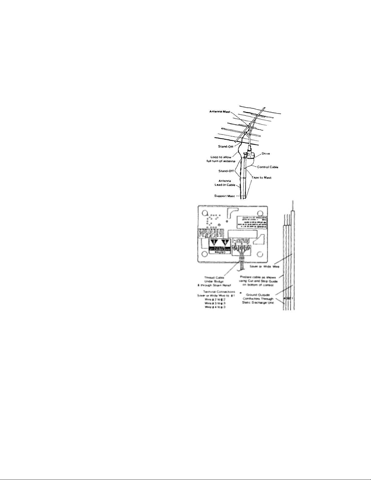
After connecting the antenna lead-in cable
igh
g
to the antenna fasten it to the antenna
mast using stand-off insulators as shown.
Provide a generous loop at the drive unit
and attach lead-in cable to the support
mast with stand-off insulators approximately every four feet. Tape the rotator control cable directly to the support mast.
NOTE: See Step 1 of the Important Safeguards Section for Grounding of Control Cable
and Lead-in Cable for Lightning Protection.
Prepare the end of the lead-in cable as
shown. Use the cut/strip guide on the
underside of the control to determine
the proper spacing and lengths. Run the
cable through the strain relief channel
on the underside of the control unit and
connect to the terminals in proper
order. The wide or silver wire is to be
connected to Terminal 1 as on the drive
unit. The next wire is connected to Terminal 2, and the next lead to Terminal
3. If 4 wire cable is used, connect both
wire 3 and 4 to Terminal 3.
ten all the terminal screws after
T
rechecking the wiring order and making
sure there are no loose strands that
could short between terminals.
Improper connections will result in i ncorrect operation of the units or per manent dama
e.
IMPORTANT: Number 1 terminal on the drive and control units must be connected
to each other, as must Terminal 2 and
Terminal 3.
With drive and control units properly wired together, plug control into
proper A.C. outlet after checking voltage and cycle data on underside of
control, Do not use D.C. Turn the control knob fully clockwise. The dot
of the indicator disc will start moving clockwise. The low sound of the
running motor will be heard from the control unit. When the antenna reaches the end of rotation, the control unit dot will stop moving and the
unit will automatically switch off. Repeat this procedure turning the
knob fully counterclockwise. When the dot reaches the north position and
switches off, the control unit and drive unit are synchronized. Turn Control knob to south 'S' to align arrows of drive unit for correct
antenna installation.
Page 5

STEP 8: RESYCHRONIZATION
Downloaded by
RadioAmateur.EU
Should the antenna position move out of synchronization with the
control unit indicator dot, turn the knob clockwise against the north
end of the rotation stop. Wait unit the dot stops moving and then turn
the knob counterclockwise against the north stop. When the dot stops
moving, units are synchronized. This procedure can be repeated whenever
needed.
STEP 9: USE OF CHANNEL MARKERS
With units synchronized as above, turn the control knob to the
position of best reception for each desired TV channel. Remove the
appropriately numbered channel marker from the label provided and
place it on the control dial face at the knob position selected for
the best reception of each TV channel.
STEP 10: OPERATING INSTRUCTIONS
To rotate the antenna,'turn the control knob to the desired reception
direction. While the antenna is rotating, the indicator dot will
move, indicating the direction of antenna rotation. When the antenna
reaches the selected direction, it will automatically stop. Do not
force the knob beyond the end of rotation stops. The rotation of the
antenna may be stopped at any time by reversing the original
direction of knob rotation just far enough to cause the dot to stop
and the control unit to shut off. '
When locating the direction of a station for the first time, rotate
the antenna several times through the point of best reception. The
correct direction can then be noted for future reference by placing
the appropriate channel marker on the dial face at this position. If
there is reason to believe that the antenna and control unit are not
tracking together, it may be necessary to synchronize the system. (See
Step 8-Resynchronization)
Page 6
IM PORTANT SAFEGUARDS
WARNING
TO PREVENT FIRE OR SHOCK HAZARD, DO NOT EXPOSE THIS
APPLIANCE TO RAIN OR MOISTURE. TO PREVENT
ELECTRICAL SHOCK, DO NOT DISASSEMBLE. NO USERSERVICEABLE PARTS INSIDE. REFER SERVICING TO
QUALIFIED SERVICE PERSONNEL. THIS UNIT FOR INDOOR
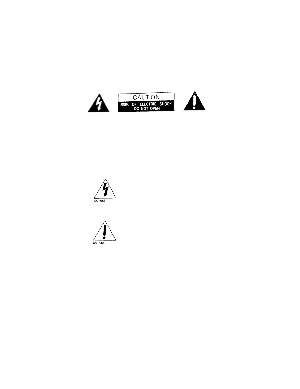
The lightning flash with arrowhead symbol,
within an equilateral triangle, is intended to
alert the user to the presence of
uninsulated "dangerous voltage" within the
product's enclosure that may be of
sufficient magnitude to constitute a risk of
electric shock to persons.
The exclamation point within an
equilateral triangle is intended to alert
the user to the presence of important
operating and maintenance (servicing)
instructions in the literature
accompanying the appliance.
"
This reminder is provided to call the CAN system
installer's attention to Article 820-22 of the NEC that
provides guidelines for proper grounding and, in
particular, specifies that the cable ground shall be
connected to the grounding system of the building,
as close to the point of cable entry as practical
Page 7
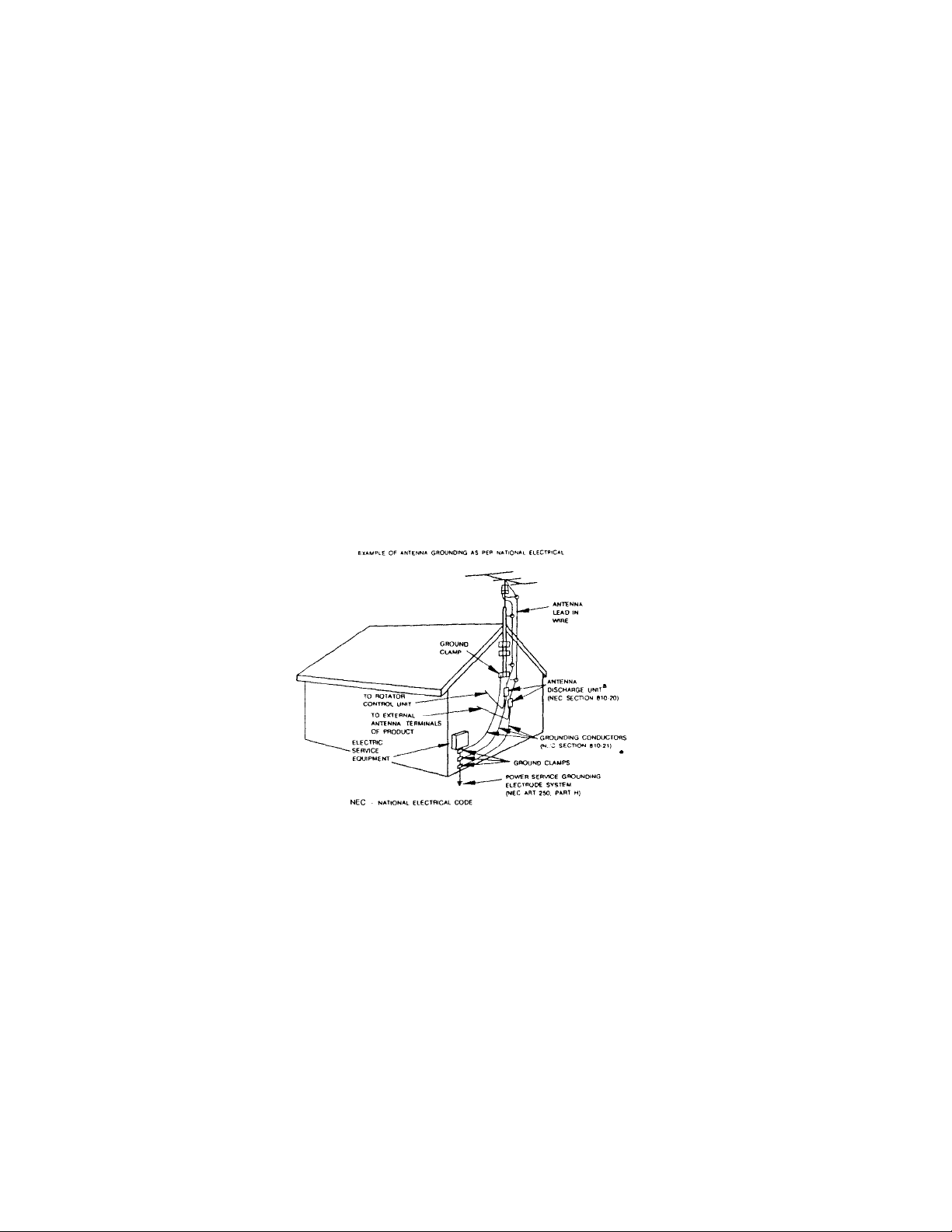
12, Outdoor Antenna Grounding - If the drive unit is installed un an
outdoor antenna, be sure the antenna system is grounded so as to
provide some protection against voltage surges and built-up static
charges. Section 810 of the National Electrial Code, ANSI/NFPA70-1984, provides information with respect to proper grounding of the
mast and supporting stucture, grounding of the antenna lead-in wire
and drive-unit to control-unit interconnecting cables to an antenna
discharge unit, size of grounding conductors, location of antennadischarge unit, connection to grounding electrodes, and requirements
for the grounding electrode. See Figure 1.
FIGURE 1
A: Use No. 10 AWG (5.3 mm^2) cooper. No. 8 AWG (6 4 mm^2)
aluminum No 17 AWG n 0mm^2 copper-clad steel or bronze
wire. or larger as a round wire
B: Secure antenna lead-in and ground- wires to house with
stand-off insulators space from 4-6 feet 11.22-t .83m) apart
C:Mount antenna discharge units as close as possible to where
lead-in and rotator wires enter house.
D: Use jumper wire not smaller than No 6 AWG 113 3 mm^2
copper. or the equivalent. when a separate antenna-grounding
electrode is used
Page 8

13. Rooftop Installation - Always use extreme caution when installing a
ightni
i
loadi
f
ici
iri
ll
h
b
liquid h
pilled i
q
liquid h
pilled i
f
d
f th
g
f
hibi
this
cates a need for se
l
i
Downloaded by
RadioAmateur.EU
rooftop antenna and rotator system to reduce the risk of falls. Wear
rubber-soled shoes and use a sturdy ladder. Do not install on a windy
day or when the roof is wet
14. L
storm, or when it is left unattended and unused for long periods of time ,
unplug the control unit from the wall outlet and disconnect the
interconnecting cable. This will help reduce the possib ility of da mage to
the product due to lightning and power-line surges.
15. Power L
located in the vicinity of overhead power lines or other electric light or
power circuits, or where it can fall into such power lines or circuits.
When installing an outdoor antenna system, extreme care should be taken to
keep from touching such power lines or circuits as contact with them may be
fatal.
16. Over
this can result in a risk of fire or electric shock.
17. Object and Liquid Entry - Never push objects or spill liquid o
kind through openings in the control-unit enclosure as they may touch
dangerous voltage points or short-out parts that could result in a risk
of fire or electric shock.
18. Serv
or removing covers may expose you to dangerous voltage or other risks.
Refer all servicing to qualified service personnel.
19. Damage Requ
outlet and refer servicing to qualified service personnel under the following conditions:
a. W
. If
c. I
e. I
. When the product ex
20. Rep
service technician has used replacement parts spe cified by the manufacturer or that have the same characteristics as the original part. U nauthorized substitutions may result in a risk o f fire or electric shock, or
other risk.
21. Serv
product, ask the service technician t o perform check to ddtermine that
the product is operating as intended.
ng - For added protection for the product during a lightning
ne - An outdoor antenna and rotator system should not be
ng - Do not overload wall outlets and extension cords as
ng - Do not attempt to service this product yourself as opening
ng Service - Unplug the control unit from the wa
en the power cord or plug is damaged.
as been s
as been s
uid has been spilled into the control-unit enclosure.liquid has been spilled into the control-unit enclosure.
li
the control unit has been exposed to rain or water.
. If the product does not operate normally when the operating inst-
ructions are followed. Adjust only those controls that are
covered by the operating instructions as improper adjustment of
other controls may result in damage and will often require
extensive work by a qualified technician to restore the product
to its normal operation.
e control unit has been dropped or the enclosure has been
ed.
dama
indi
acement Parts - When replacement parts are required, be sure the
ce Check - Upon completion of any service or repairs to this
or is covered with ice or snow.
nto the control-unit enclosure.
nto the control-unit enclosure.
ts a distinct change in performance -
rvice.
any
 Loading...