

Page 1

HAM V / HAM VX
g
,
Antenna Rotator System Including
DCU-1 Di
Instruction Manual
ital Controller
308 Industrial Park Road
Starkville
MS 39759
Page 2

TABLE OF
Page CHAPTER 1 - Installation and
Operation................................................................................................ l-1 Section 1. Components of
the HAM-V ................................................................................................1-1 General
.............................................................................................................................................1-1 Section 2.
Specifications ......................................................................................................................1-2 Section 3.
Precautions ..........................................................................................................................1-4 Section 4.
Installation Preparations ......................................................................................................1-5 Types of
Installations .......................................................................................................................1-5
Precautions .......................................................................................................................................1-8
Section 5. Wiring and Check-Out ........................................................................................................1-9
Section 6. Installing the Rotator.........................................................................................................1-11
Inside Tower Mount.......................................................................................................................1-11
Outside Tower Mount ....................................................................................................................1-13
Mast Mount ........................................................................ 1-13 Section 7. Optional Accessory
Kits....................................................................................................1-14 Section 8. Operation of DCU-
1 Pathfinder Control Unit...................................................................1-15 Precautions
.....................................................................................................................................1-15 Normal
Operation...........................................................................................................................1-15 Computer
Operation .......................................................................................................................1-16 Section 9.
Troubleshooting.................................................................................................................1-18 Ground
Wires .................................................................................................................................1-19 Antenna
Motion..............................................................................................................................1-19 Lack of
Power ................................................................................................................................1-19 Checking
the Control Unit Voltages ..............................................................................................1-20 Checking
the Rotator Resistances from the Ground ......................................................................1-20 Section 10.
Disassembly of the Rotator Unit .....................................................................................1-21
Spur Gear Assembly 122 Section 11. Reassembly of the
Rotator...............................................................................................1-23 Section 12. HAM-V Rotator
Replacement Parts.......................................,........................................1-24 Section 13. DCU-1 Control
Unit Block Diagrams.............................................................................1-29 Section 14. DCU-1 Control
Unit Replacement Parts List..................................................................1-30 Section 15. How To Get
Factory Service.......
w ....................................................................................1-31
Warranty
-
Page 3

Figure Pag
1 Front View .......................................................................................................................1-3
2 Back View........................................................................................................................1-3
3 Rotator Mounted Inside.................................................................................................... l-5
4 Rotator Mounted on Tower Top Plate..............................................................................1-6
5 Pole Mounted Rotator ......................................................................................................1-7
6 Control Cable Connector Attachments.............................................................................1-9
7 DCU-1 Display...............................................................................................................1-10
8 Rotator Mounting in a Tower.........................................................................................1-11
9 Rotator Mounting with (optional) Lower Mast Support ................................................1-12
10 Wiring Guide..................................................................................................................1-16
11 Command Set.................................................................................................................1-16
12 Sample Program .................................................. .........................................................1-17
13
Spur Gear Assembly
14 Inside View of Ham-V Rotator......................................................................................1-25
15 BrakeAssembly and Terminal Board Wiring Detail ......................................................1-26
16 Ham-V Rotator-Illustrated Parts Breakdown .................................................................1-28
17 Front Panel PCB, Block Diagram ..................................................................................1-29
18 Control PCB and External Components, Block Diagram ..............................................1-29
1
Control Cable ...................................................................................................................1-
2 Troubleshooting .............................................................................................................1-
3
Control Unit Voltages ....................................................................................................1-
4 Rotator Resistances ........................................................................................................1-
Page 4

General Description
g
p
.
CHAPTER 1 INSTALLATI ON AND
-
The Ham-V rotator system consists of a heavy
duty rotator and the new DCU-1 "Pathfinder"
digital control unit. The rotator is designed to be
mounted on a plate inside a communications
tower, and is attached to a vertical steel mast. The
DCU-1 control unit must be installed indoors and
connected to the rotator by an 8 conductor cable.
The DCU-1 "Pathfinder" digital control unit features 6 memory presets, automatic brake delay (8
seconds), automatic motor slowdown (last 5 degrees), automatic motor control on startup, programmable center of rotation, full circle analog
display of current and target bearings, digital display of current and target bearings, automatic display blanking of target bearings (30 seconds),
automatic display blanking (30 minutes), RS-232
control with pass-through, and an 8 pin socket for
the control cable.
The Ham-V rotator features low temperature operation (-30 deg. F/ -34 deg. C), a weatherproof
AMP connector with gold-plated contacts, an improved high-strength steel drive gear, RF beads
on the potentiometer lines, wedge brake, and safe
26 volt operation.
The Ham-V rotator system consists of the followin
main components:
P/N 5137202 Ham-V Rotator Assembly
P/N 870804 DCU-1 Control Unit Assembly (110
VAC)
P/N 870842 DCU-1 Assembly Control Unit (220
It is recommended that you use this rotator system
with compatible antennas and towers. For example, the maximum antenna size for this system is
15 sq. ft. (1.4 sq. m). Therefore, if you anticipate
using antennas near this limit, the tower system
should also be rated for wind areas of this magnitude. If you are considering antennas with long
booms and/or long elements, do not exceed the
Effective Moment specification of 2800 ft. lb.
(387 Kg m). EM is defined as the antenna turning
radius times weight. Antennas with long booms
and elements have much more angular
momentum and exert more torque on rotator
systems than antennas with shorter booms and
tions:
O
The Ham-V also features a rugged powder-coat
The rotator unit must be connected to the control
unit with an 8-wire cable. You may assemble
your own cable from the information supplied in
this manual
The optional heavy-duty lower mast support kit
must be procured if you elect to use a mast mount
(see Figure 5 and 9). The part number for this kit
is 51467 10. When using the lower mast support,
the antenna size is restricted to 7.5 square feet of
wind area. The "inside tower mount" configuration is recommended (see Figure 3 and 8).
A 3 foot cable with a pre-assembled AMP
connector may be ordered as product 307-3. The
other end of the cable has bare wires. You must
supply the connector for this end!
Page 5

Section 2.
Page 6

DCU-1 Digital Control Unit:
(
)
Control Unit
Display: Type
Scale
Blankin
Display Life Memory
Presets Rotation Center
Brake Delay Automatic
Motor Control
8.5"x4.3"x9.0" (WxHxD)
21.6x 11.0 x22.8 cm
Gas Plasma, Amber filter
5 degree (Analog), 1 degree (Digital)
Target Bearing ( 8/60 seconds) Total
( 30 minutes after no activity)
30,000 to 40,000 hours
6, independently programmable
User selectable, 0 - 360 degrees
8 seconds, fixed
- momentary reverse direction on start-up
-automatic stop if no rotator movement detected in 8 seconds
- motor pulse (half-cycle) on last 5 degrees before stop
1 Knob ( 36 pos. digital
encoder) - sets target bearing
- sets center of rotation in calibrate mode
- increment of 1 degree (slow speed
mode) and 7 degrees (high speed mode)
6 Memory Preset ( pushbuttons)
1 Start Rotation ( pushbutton)
- also starts EPC (calibration)
1 Stop Rotation ( pushbutton)
1 Display ( pushbutton)
- turns on display after
blanking - enters calibration
mode
1 8-pin socket (rotor
Figure 1 Front
View
Page 7

Section 3. Precautions
,
)
Towers and antennas require caution during erection and placement! Extreme care must be taken
during erection so that metal tower and antenna
parts DO NOT contact power lines, even if the parts
slip, rotate, retract, fall or fracture!
Antenna position mechanisms (towers and rotators)
must be placed so that if they fail, the parts of the
antenna system cannot contact power lines, be a
hazard to individuals
or endanger property.
Metal towers must be grounded properly at the
tower location before the tower is erected. This is to
minimize electrical hazard and the possibility of
lightning damage. DO NOT bury bare aluminum
wires or stakes in the ground. Use copper or copperclad ground stakes. The service entrance ground
should be checked. The household convenience
outlet should be th e 3 -pron g type (grounded b ack to
the service entrance
.
NOTE:
This equipment has been tested and found to
comply with the limits for a Class B digital
device, pursuant to part 15 of the FCC Rules.
These limits are designed to provide reasonable
protection against harmful interference in a
residential installation. This equipment generates,
uses and can radiate radio frequency energy and
if not instal led and used in acco rdance with the
instructions, may cause harmful interference to
radio communications. However, there is no
guarantee that interference will not occur in a
particular installation. If this equipment does
cause harmful i nterference to radio or television
reception', "which can be determined by turning
the equipment off and on, the us er is e ncouraged
-
- Increase the separation between the
It is recommended that you use a "daisy-chain"
ground connection rather than connecting all units
(DCU-1, radio, tuner , etc.) to the ground rod separately.
The DCU-1 Control Unit is not weatherproof and
must be located in a house or other protected location. Connect a ground wire to the 1/4"-20 terminal
on the back of the DCU-1.
- Connect the equipment into an outlet on a
circuit different fro m that to which the
- Consult the dealer or an experienced
radio/TV technician for help.
The Ham-V rotator system has been carefully designed and manufactured to give many years of
trouble-free service when carefully and professionally installed. It consists of the strongest and best
commercially available components. This product
is manufactured in the U.S.A.
Page 8

Sectio
n 4. Installation Preparation
s
y
Types of installations:
There are three general types of rotator
installations (see Figures 3, 4, and 5).
l. The recommended installation is an "inside"
tower mount with a thrust bearing or bushing
to provide vertical and horizontal support. The
thrust bearing should mount on the top surface
of the tower and should fit the size of mast
ou are using.
The rotator shelf should be at least three (3 ) feet
below the thrust bearing. If a single antenna is
mounted on the mast, it should be no more than
one (1) foot above the thrust bearing. The thrust
bearing should be of commercial manufacture and
should properly fit the tower that it is attached to.
If your installation follows these guidelines, this
rotator system will easily handle an antenna
system of 15 sq. ft. wind area or EM of 2800 ft.
Figure 3 Rotator
Page 9

2. An "outside" tower mount may be used when
p
the rotator unit will not fit within the tower, or
there is no rotator shelf provided. In this
installation, the rotor mounts on a flat plate at
the top of the tower. There is no thrust
In this application, it is extremely important that
the antenna is mounted no more than six (6)
inches above the top of the rotator. If these
guidelines are followed, the rotator system will
easily handle a single antenna with a 7.5 sq. ft.
Figure 4 Rotator Mounted on Tower
To
Plate
Page 10

3. A telescoping or other type mast may also be
used. This installation requires the optional
"Heavy Duty Lower Mast Support Kit". In this
application, it is extremely important that the
antenna is mounted no more than six (6)
inches above the top of the rotator.
If these guidelines are followed, the rotator
system will easily handle a single antenna with a
7.5 sq. ft. wind area or EM of 1125 ft. lb. Ensure
There -are variations of mounting which fall
generally into one of the above categories. For
example, the rotator may be mounted much lower
in the tower than described. In this case, more
than one mast bearing may be required.
Figure 5 Pole Mounted
Page 11

1. Unbalanced weight: Weight should be as
p
p
closely balanced as possible. Unbalanced
weight in an antenna creates a bending
moment of force which is concentrated on the
mast at the
2. Wind Pressure: Balanced wind pressure against
the antenna system produces a bending force
on the mast which can cause the same stress es
as unbalanced weight. To minimize these
forces, a thrust bearing should be used where
possible, the antenna should be as close to the
top of the tower as possible and the rotator
shelf should be as low as
oint where it is clamped to the
ossible.
3. Unbalanced Wind: If the antenna has unequal
wind areas and element spacings on each side
of the mast attachment point, it could produce
torque on the support mast. This is similar to
the principle of a weather vane. If the
unbalance is high enough or the wind velocity
is high enough, this could prevent rotation or
could damage the limit switches. To minimize
this effect, the antenna should be designed for
minimum mast torque or "torque
compensators" added to produce minimum
4. Mast Binding: If the antenna support mast
binds withig. the tower due to ice
accumulation or other reasons, this could
prevent rotation. The DCU-1 checks for
rotator movement upon pressing "START",
and if no movement is detected within 8
5. Extreme Cold: If the ambient temperature is at
or below -30 degrees F, this could prevent
rotation. If no movement is detected within 8
seconds of pressing "START", then the rotator
Page 12
Section 5. Wiring and Check-
g
Wiring and Check-Out
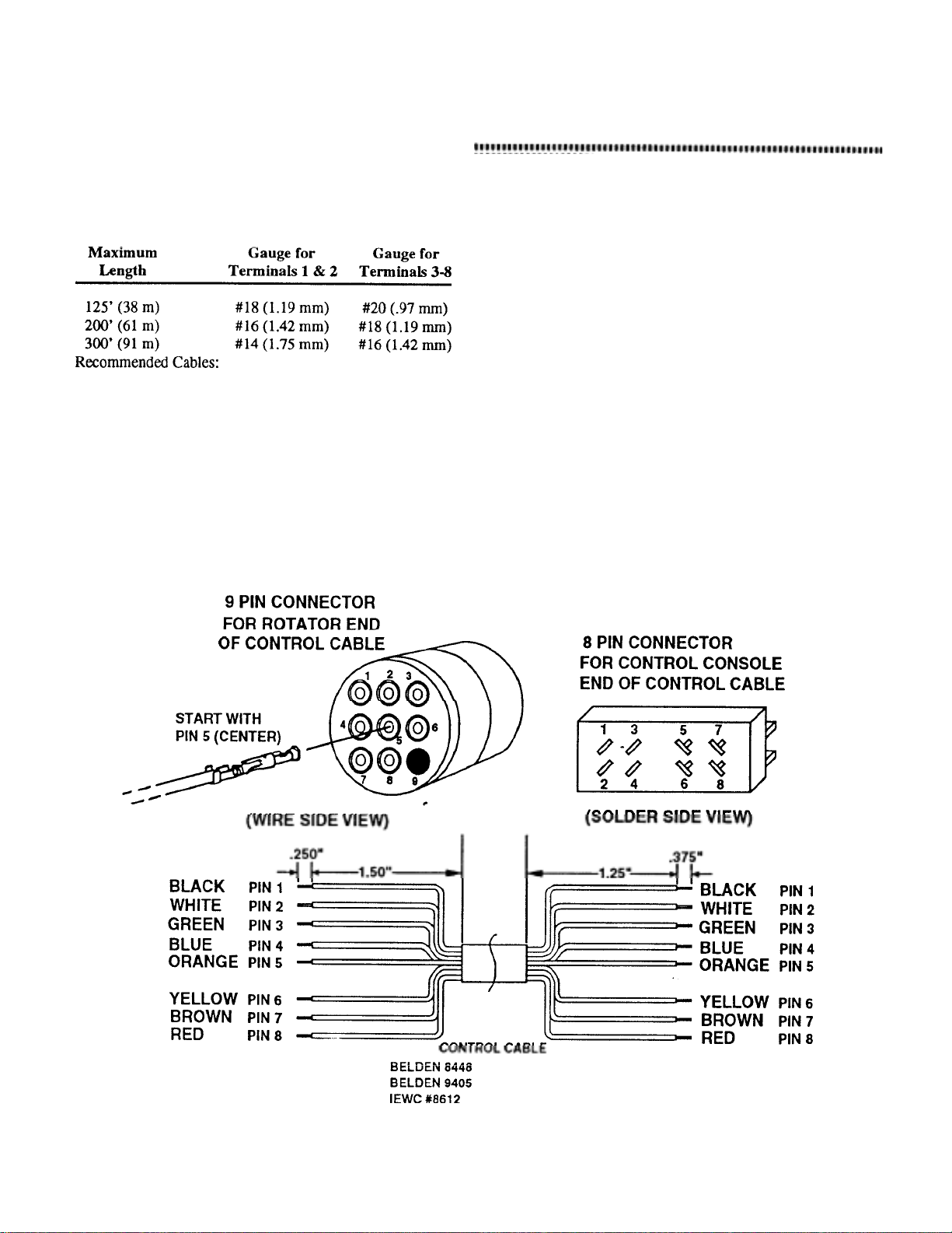
1. Determine the length of control cable required
and find the wire gauge (size) required from
Belden 8448
Belden 9405
TABLE 1
NOTE: The specifications call for heavier gauge
wire in two locations. Leads #1 and #2 must be
2. Assemble the rotator cable as shown in Figure
6, or purchase a pre-assembled cable.
CAUTION
Shorts between terminals or grounded leads may
damage the rotator. Check the numbered pins on
each connector with an .
3. Temporarily attach the 4 screws, 1/4" - 20 x 1
1/4" (Item 147) to the bottom of the rotor
unit. These will be used to support the rotator
durin
4. With the rotator sitting in the upright position
andconnected to the control unit by the 8-wire
cable, plug the control unit power cord into a
receptacle. At this time, the rotator brake
wedge may momentarily release and re-
bench-testing.
Figure 6 Control Cable Connector
Page 13
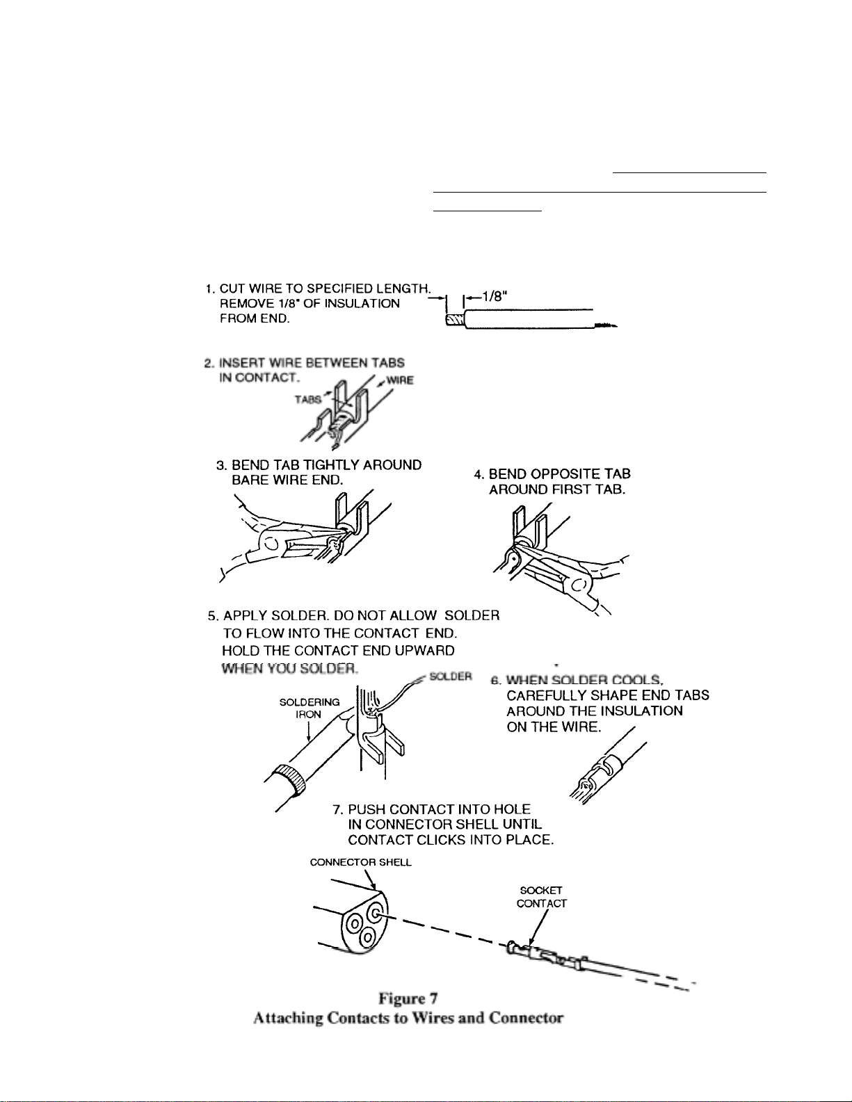
Attaching Contacts to Wires and Connector
g
Since these contacts will be inserted into
connector blocks, their tabs must be carefully
rounded. Unless you have a crimping tool for
installing connectors, use the followin
Repeat for each contact. Pay close attention to the
numbered holes in the connector! Pull back
lightly on each conductor to be sure each contact
is locked in each cavity. Once locked in place,
the contacts may only be safely removed with an
extraction tool. This tool consists of a tube with
an OD of 0.129 and an ID of 0.115. When
inserted over the contact from the front side, this
tool compresses the locking tabs, permitting easy
-
Page 14
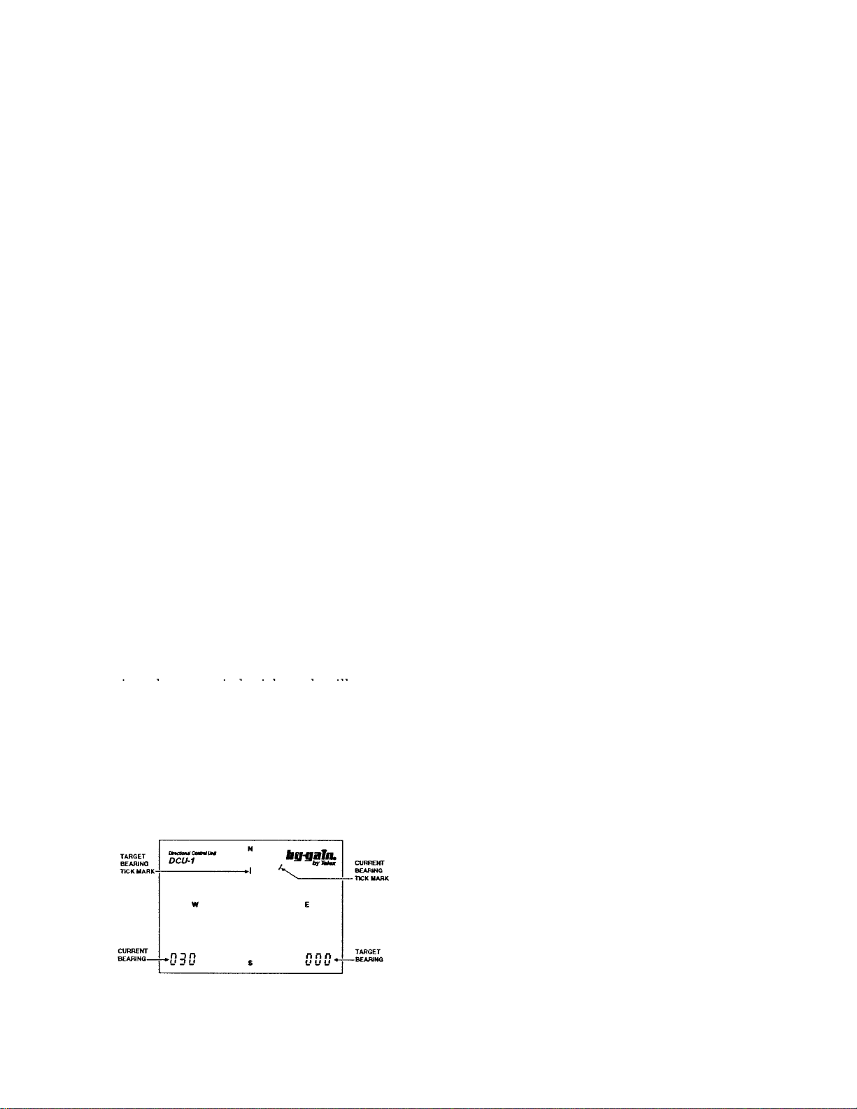
5. The DCU-1 "Pathfinder" display should look
g
play
y
y
y p
similar to the display shown in Figure 7. The
numeric displa y in the lower left corner indi cates
the current bearing of your rotator. The numeric
display in the lower right corner indicates the
target bearing. If both displays read a steady
"000", disconnect your control cable and check
the cable wirin
with an ohmmeter. Proceed if the
NOTE: Push the "DISPLAY" button to return normal
display. After approximately 60 seconds of
inactivity, the target digital and analog displays will
blank (disappear). After 30 minutes of inactivity, the
entire di s
will blank.
6. If the current bearing display shows a number between "001" and "359", then proceed. Twist the
knob marked with the two (2) arrows "W. The
target bearing display should change along with
the inner circle tick mark. The knob will
increment at 1 degree per "click" at slow speeds
and 7 degrees per " click" at faster speeds. Using
the knob, select a target bearing at least 30
degrees from the current bearing. Push the
"START" button. The brake i n the rotator should
release, the rotator will turn a few degrees in the
opposite direction, reverse direction, then turn to
the target bearing. During the last 5 degrees, the
rotator will slow down to half speed, then stop on
or close to the target bearing. The brake solenoid
will "hum" for 8 seconds, then the brake will
engage. Target display blanking will occur
simultaneously with brake engagement. During
8. Decide on the mechanical center of rotation at this
time. For example, if you would like to rotate
from East to West through South, then South
(180 degrees) is your center of rotation. The
center of rotation can be selected as any bearing
between "000" and "359". Press "DISPLAY" and
hold until th e letters "CAL" appear in the center
of the display. The rotator should automatically
turn to the mechanical center of rotation. When it
has reached this position, the letters "SET" should
appear in the center of the display. Twist the
knob until the desired center of rotation is
The knob will inc re men t 1 de gr ee pe r "c lic k" at
"
"
Press the "START" button and hold until the
rotator starts to turn. The rotator will
automatically find both limit switches and set up
the calibration for the center of rotation you
selected. During this time, the letters "EPC" will
be displayed for "End Point Calibration". When
this process is finished, the "EPC" will disappear,
and the rotator is read
for use. If you wish, you
9. Yo u may se t th e memo ry pr eset s at thi s ti me or at
any time after the rotator system has been
installed. To store a bearing into a memory
location, select a target bearing with the knob
then press and hold the appropriate memory
location button until the letters "PRE" light up.
You ma
use previously stored memory presets
7. You may wish to repeat step 6 to confirm
operation over a wide range of bearings. If the
"STOP" button is depressed during rotation,
rotation will stop and the brake will engage 8
seconds later. If the operation is consistent,
Figure 8 DCU-1
Display 1-11
10. Rotate the system to the center of rotation. You
are now ready to install the rotator system in your
Hints:
Some users have labeled their memory buttons
with the stick-on letters supplied with VCR
tapes. Use EU for Europe, JA for Japan, AU
for Austrailia, AF for Africa, etc.. Place the
labels next to each of the 6 memor
resets,
Page 15
Installing the Rotator
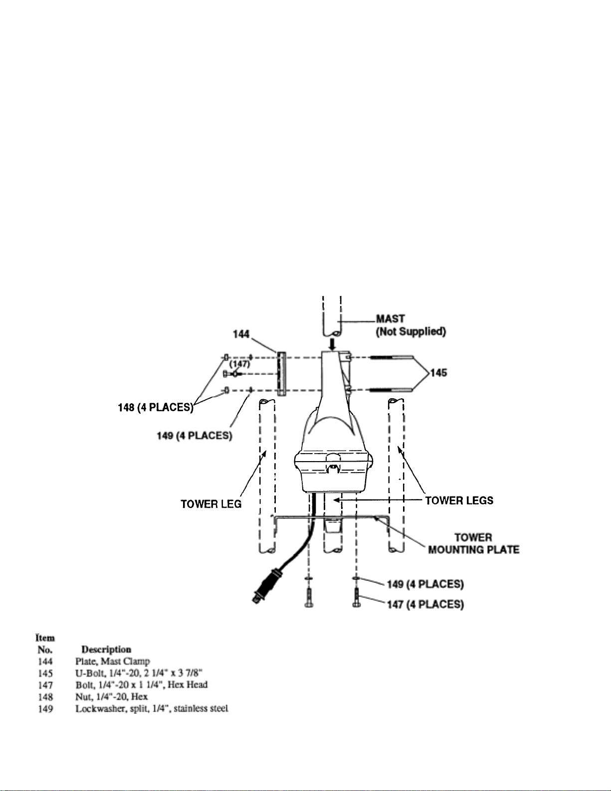
The rotator is mounted inside a tower, see Figure
3 and 8, to the flat tower plate by means of four
(4) bolts furnished in the hardware kit. Use the
following procedure:
1. Position the rotator in the tower directly under
the thrust bearing. The tower plate mu st be cut
out to allow the connecting 8-wire cable with
connector to pass through the plate. If a new
hole must be made, use the template in the
back of this manual.
2. Attach the rotator to the tower plate by means
of four (4) bolts and lockwashers (see Figure 3
and 8). The flat tower plate must be drilled in
four (4) places using the template provided
with this manual unless the tower plate is
already properly drilled. Tighten the four (4)
Figure 9 Rotator Mounting in a
Tower
-
Page 16

3. Attach the control cable to the rotator connector as
g prop
p
g
p
g
g
before. Using the DCU-1 control unit, turn the
rotator and observe rotator movement. If
everything works properly, secure the cable to the
tower usin
er strain-relief techniques.
6. Turn the rotator using the DCU-1 control. Observe
mast movement throughout full 360 degree
rotation. If any binding occurs, reposition the
rotator on the flat
late and retighten the mountin
4. Assemble the mast to the rotator using the U-bolts,
nuts, lockwashers, and clamp plate as shown in
Figure 8. Apply a coating of heavy-duty motor oil
or grease to the threads of the stainless steel Ubolts to
revent seizing. Do not tighten at this time.
5. Center the mast within the tower thrust bearing and
secure the thrust bearing to the mast. Turn the mast
by hand to check for binding within the tower.
Adjust the thrust bearing if required. If no binding
occurs, then tighten the rotator U-bolts to secure
the mast to the rotator. Install and tighten the center
mast bolt at this time. See Fi
ure 8.
CAUTION:
Do not use masts with an O.D. less than 17/8"
with a thrust bearing! It is important that the
rotator does not try to turn the mast
7. Position the rotator to the center of rotation using
the DCU-1 control unit. Attach the directional
antenna so that it points the same direction. The
coaxial cable should be attached to the mast and
tower so that the rotator can freely move in both
directions to the ends of rotation. The coaxial cable
should be flexible enough to permit rotation
without dama
e. Do NOT use Belden 9913 cable
Page 17

The rotator is mounted to the top surface of a
g
g
g prop
g
y
tower, see Figure 4, by means of four (4) bolts
furnished in the hardware kit. Use the followin
1. Position the rotator on the top surface of the
tower or other support structure and attach by
means of four (4) bolts and lockwashers. The
top of the tower must be cut out to allow the
connecting 8-wire cable with connector to
pass through the plate. If a new hole must be
made, use the template in the back of this
manual. Ti
2. Attach the control cable to the rotator
connector as before. Using the DCU-1 control
unit, turn the rotator and observe rotator
movement. If everything works properly,
secure the cable to the tower usin
3. Assemble the mast to the rotator using the U-
bolts, nuts, lockwashers, and clamp plate as
shown in Figure 4. Apply a coating of heavyduty motor oil or grease to the threads of the
stainless steel U-bolts to prevent seizing.
Tighten all bolts securely.
4. Position the rotator to the center of rotation
using the DCU-1 control unit. Attach the
directional antenna so that it points the same
direction. The coaxial cable should be attached
to the mast and tower so that the rotator can
freely move in both directions to the ends of
rotation. The coaxial cable should be flexible
enough to permit rotation without damage. Do
NOT use Belden 9913 cable in this rotation
hten the four (4) bolts.
er
CAUTION:
The rotator is mounted to a vertical mast, see Figure 5 and 9, by means of four (4) bolts and the
optional lower mast support, P/N 5146710. Use
the following procedure:
1. Attach the rotator to the lower mast support
by means of four (4) bolts, nuts and
lockwashers. Tighten the four (4) bolts. Attach
this assembly to the top of the mast as shown
in Figure 5. Tighten all bolts securely.
2. Attach the control cable to the rotator
connector as before. Using the DCU-1 control
unit, turn the rotator and observe rotator
movement. If everything'works properly,
secure the cable to the mast using proper
3. Assemble the top mast to the rotator using the
U-bolts, nuts, lockwashers, and clamp plate as
shown in Figure 8. Apply a coating of heavyduty motor oil or grease to the threads of the
stainless steel U-bolts to prevent seizing.
Tighten all bolts securely.
4. Position the rotator to the center of rotation
using the DCU-1 control unit. Attach the
directional antenna so that it points the same
direction. The coaxial cable should be attach ed
to the mast and tower so that the rotator can
freely move in both directions to the'ends of
rotation. The coaxial cable should be flexible
enough to permit rotation without damage. Do
NOT use Belden 9913 cable in this rotation
NOTE: Belden 9913 Coax has a solid center conductor and an air-space dielectric. It is not
flexible enou
h to use in a rotation loop.
This rotator is designed for vertical operation
with the bell-shaped housing pointing straight
up. Do not mount this unit either horizontall
Page 18
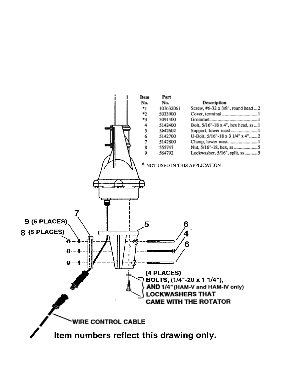
Section 7. Optional Accessor
y
Optional Heavy-Duty Lower Mast Support Kit
This kit contains a heavy-duty lower mast
support and the necessary hardware to facilitate
mounting
the rotntor on s mact
CAUTION:
When the rotator is installed using the lower
mast support kit, the antenna size must be
restricted to 7.5 square feet ( 0.7 sq. m. ) of
Figure 10 Rotator Mounting with (optional) Lower Mast
Support 1-15
Page 19

Section 8. Operation of DCU-1 "Pathfinder" Control
y
Operation of DCU-1 Control Unit
Normal Operation
l. Thermal Protection: If the rotator fails to turn
after 4 or 5 minutes of continuous operation,
the thermal switch has come into play. This
protective device in the transformer assembly
automatically shuts off power if the
transformer becomes too hot. It will
automatically reset after approximately 10
2. Display Protection: The gas-plasma display
will be turned off during periods of inactivity
to extend its useful life. After approximately
30 to 45 seconds of inactivity, the target
digital and analog displays will blank
(disappear). After 30 minutes of inactivity, the
entire display will blank. Push the
"DISPLAY" button to return normal display.
3. Brake Wedge Protection: The brake wedge
will only engage after waiting eight seconds
after removing power from the motor. This
allows large antenna systems to coast to a
complete stop before engaging the brake. Even
if the "STOP" button is pressed, the system
will still wait eight (8) seconds before
dropping the brake. The brake will
immediatel
-.--.-..------.-.------CAUTION; -----..-.-------.----.
Do not reverse rotation direction during
rotation! This will cause the system to hang
with the brake released. Pressing "STOP" will
reset the system.
engage if AC power is
The numeric display in the lower left corner and
the outer circle tick mark always indicates the
current bearing of your rotator. The numeric
display in the lower right corner and the inner
circle tick mark indicates the target bearing. This
display is also used during calibration to select
the center of rotation. The center alpha-numeric
display is used during the calibrate routine and to
indicate memory preset selections. The tick marks
may fluctuate betweer(two marks if the rotator is
moving in the wind and the digital bearing ends
To move the rotator to a new bearing, either the
knob, memory presets, or a combination of these
may be used to select the new bearing. To start
rotation to this new bearing, press "START". The
brake in the rotator will release, the rotator will
turn a few degrees in the opposite direction,
reverse direction, then turn to the target bearing.
During the last 5 degrees, the rotator will slow
down to half speed, then stop on or close to the
target bearing. The brake solenoid will stay on for
8 seconds, then the brake will engage. The target
display will also blank simultaneously. During
rotation, the outer circle tick mark will move to
If the "STOP" button is pressed during rotation,
rotation will stop and the brake will engage 8
To store a bearing into a memory location, select
a target bearing with the knob then press and hold
the appropriate memory location button until the
letters "PRE" light up. You may use previously
stored memory presets and the knob to select new
bearings to store.
NOTE: The rotator may end up a few de grees off
the desired target bearing. This is because the
brake wedge locks into place every five (5)
degrees. This should not cause any problems in
most HF and VHF installations.
Page 20
Computer Operation
y
The
DCU-1
computer via a
rear panel has two (2)
connector marked "HOST"' is a
may be controlled from your
RS-232
cable connection. The
RS-232
connectors. The
DB9
female
connector and should be directly connected to the
host computer.
not use a null-modem
Do
connection. The connector marked "EXT" is a
DB9
male connector and should be connected to
other ham equipment such as a modem, TNC, or
radio interface unit. If the "EXT" connector is not
attached to other equipment, it should be
terminated with the supplied plug. The supplied
termination plug shorts
DTR,DSR
and
DCD
(Pins 4,6, 1) together and RTS and CTS (Pins 7
Your other computer peripheral equipment should
connect to the "EXT" connector as they would
normall
connect to your computer com-port.
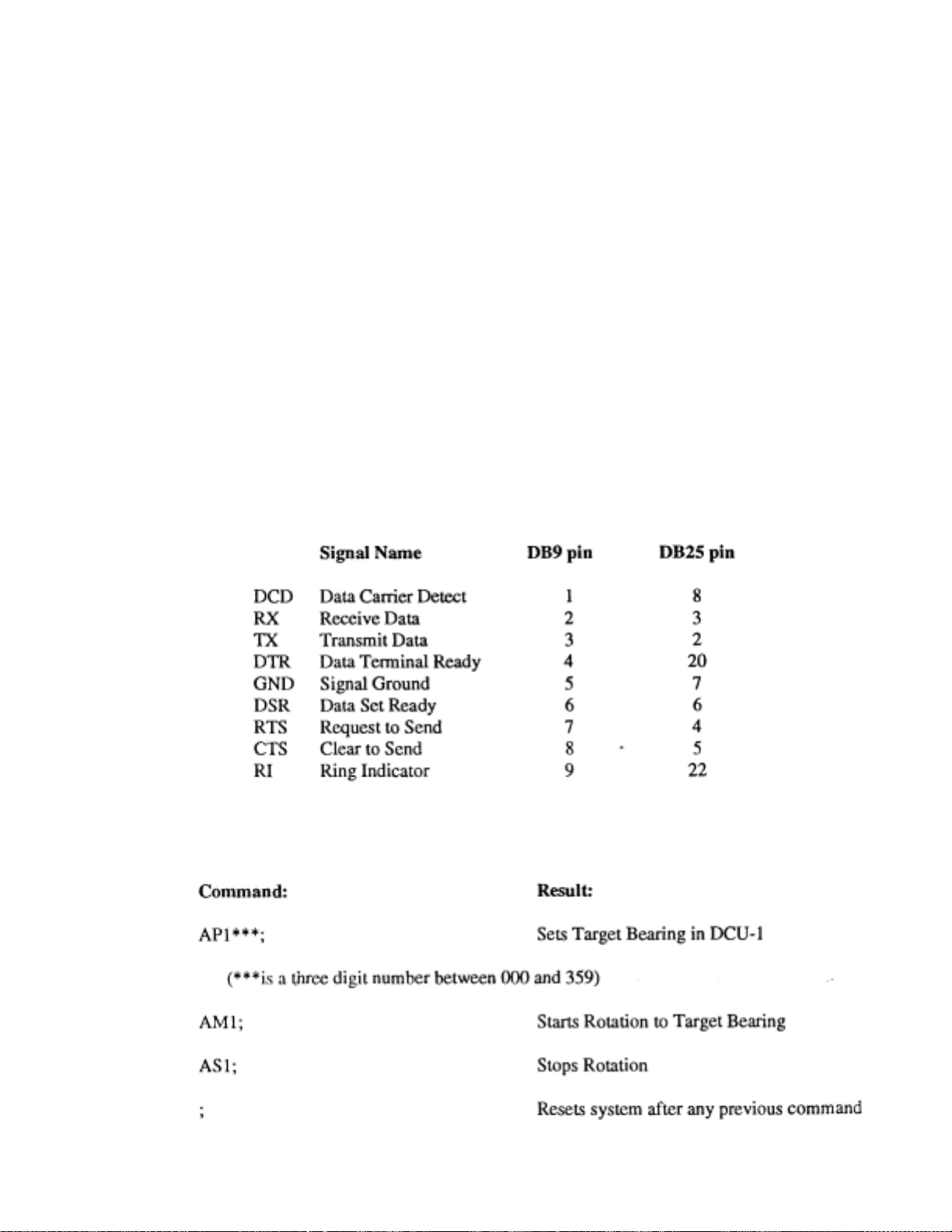
The cable which is attached to the computer and
to the
DCU-1
connector at one end and either a
DB25
female connector at the other end. The
should have a
DB9
DB9
female or
male
connections should be straight through, e.g. pin 1
to pin 1, pin 2 to pin
pin connectors. If a
used to attach to the computer's COM 1 or
etc if both ends have
2,
DB25
female connector is
COM2
port, use the wiring guide shown in Figure 10.
You may also purchase a pre - assembled cable
from Hy-Gain to connect your computer to the
DCU-1.
Order either
DCU-9P
or
DCU-25P
9
Figure 11
Wiring Guide
Figure 12
Command Set
-
Page 21
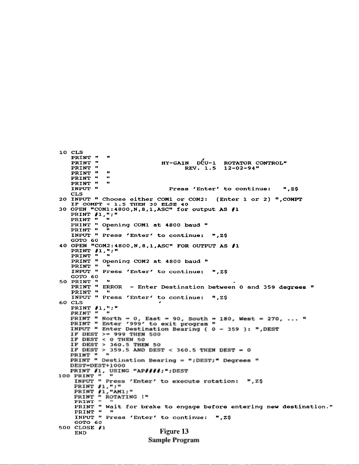
A sample BASIC program is shown in Figure 12
which can be used to control operation of the
DCU-1. Other software vendors may also include
the ability to directly control the DCU-1 from
within a logging or rig control program.
The commands are similar to those used by Kenwood in controlling radio operations. A summary
of unique commands is shown in Figure 11. The
COM port should be used at 4800 baud with no
parity, 8 data bits, 1 stop bit and ASCII mode.
This is usually shown as "4800,N,8,1,ASC".
After a command is sent to the DCU-1, all other
motor and brake operation is automatic. There are
no provisions at this time to send current bearing
information back to the computer.
You may wish to check with our Customer
Service Department from time to time in order to
obtain the latest firmware upgrades. See Section
16, page 32. Phone (402) 467-5321 or (402) 465-
Page 22
Troubleshootin
g
p
Section 9.
CAUTION: This unit has been thoroughly tested
and cycled before shipment. Follow the connector
wiring carefully between the rotator and the
DCU-1 control box. Pin #1 must attach to Pin #1,
etc... Incorrect wiring will burn out the rotator
otentiometer and void the warranty.
The DCU-1 control box is designed to be used
ONLY with Hy-Gain HAM-IV, HAM-V, and
T2X rotator systems. Do not t r y to use this
control on other systems!
-
Page 23

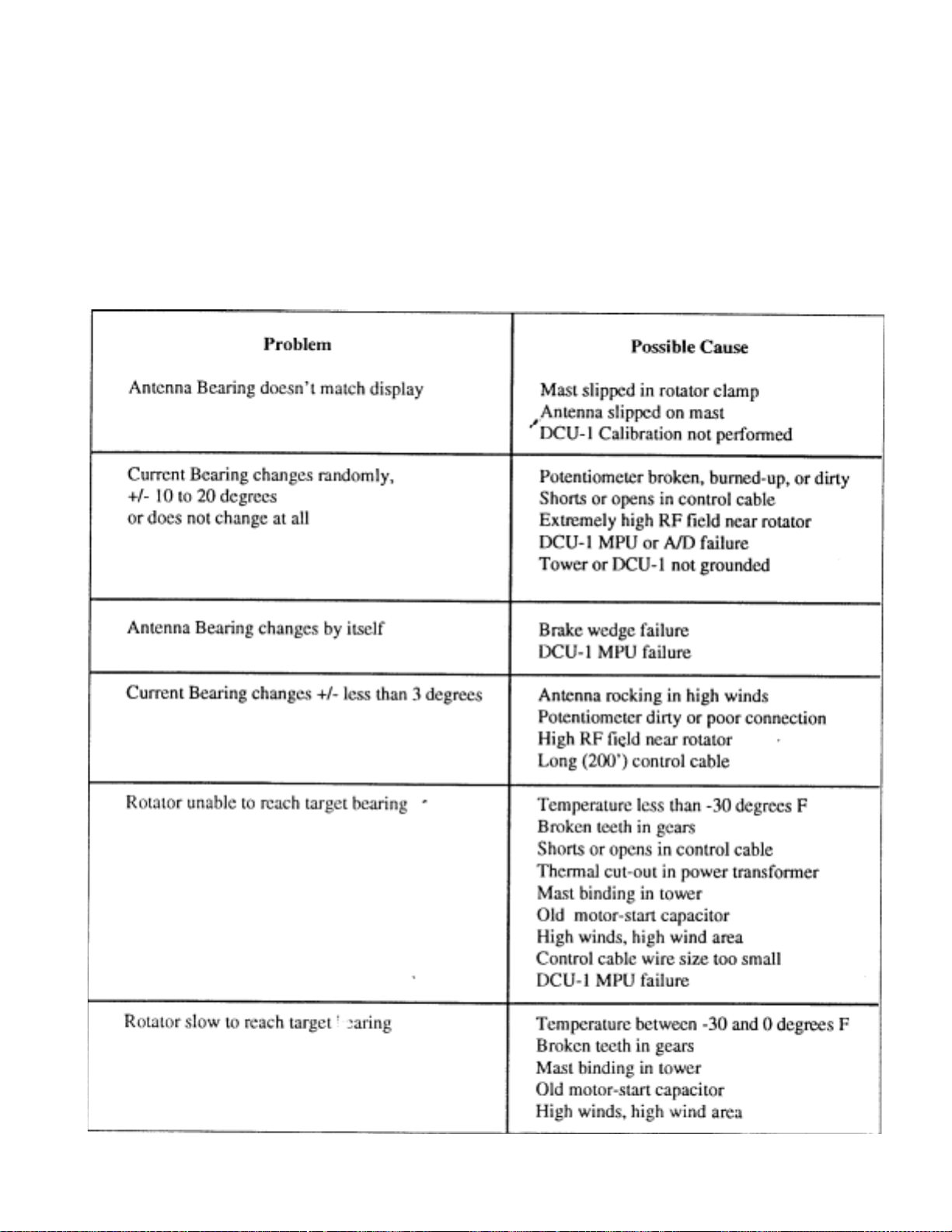
Most operational difficulties with rotators are
g
traceable to broken, shorted, grounded or
miswired control cables. Time spent on
assembling, routing and protecting the control
cable will lead to a lon
Unintentional grounds on cable leads can burn
out the line fuse in the DCU-1 control box, the
A/D IC, or the potentiometer in the rotator. If pin
#3 or pin #7 is grounded, it shorts out part of the
potentiometer so that as rotation progresses to the
other end, the full DC voltage is applied across a
decreasing portion until current becomes so high
that the potentiometer or the voltage regulator
burns out. Note also that any grounds may put an
overload on the power transformer which could
cause the line fuse to blow.
Frequently the slight motion of the antenna arra y
in gusts of wind is due more to the natural flexing
of the elements and mast than to actual play in
the rotator mechanism. A slight amount of "play"
is built into the rotator to avoid binding due to
environmental changes.
trouble-free rotator life.
If the antenna rotation is slow or sluggish or hard
to start, check for proper voltages on pins #2,5,
and 6 (See Table 3). If the voltages are correct,
the 130 - 156 MID capacitor may be old. If your
unit is more than 5 years old, try replacing this
capacitor. Also, if your cable run is over 200 feet,
make sure that you are using the proper wire size.
See Table 1. For cable runs over 300 feet, you
may wish to move the motor capacitor to the
tower. This allows you to run only 6 wires from
the control to the rotator, so that you can reduce
wire resistance by doubling up wires or using
If the electrical circuit is working, then check for
mechonical problems. Look for mast binding or
thrust bearing misalignment if you have experienced strong winds recently. If the temperature is
less than -30 deg. F ( -34 deg. C ), the rotator will
be very sluggish or may not run at all! This is
normal. Do not try to rotate with the DCU-1 control if temperatures are below -30 deg. F !
If the antenna actually rotates in high winds, this
is usually just the mast slipping in the rotator or
the antenna slipping on the mast. For large
antennas,, it is often necessary to drill a 5/16" hole
through the rotator clamping plate and mast and
pin them together with the bolt provided. Also, if
possible, pin the antenna to the mast with
appropriate hardware. If slipping is suspected,
return the rotator to an end of rotation limit and
visually check antenna alignment.
Page 24
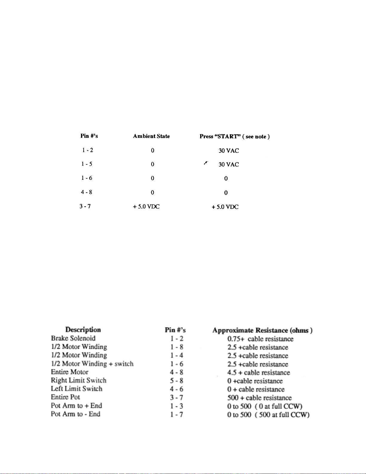
Checking the Control Unit Voltages
g
e following resis
ces:
To check the control unit voltages, first remove
the rotator control cable from the DCU-1 control
box, then plug the line cord into a 120 or 220
With no connections, the front panel display
should read "000" on the current display and
"000" on the target bearing display. Check for the
followin
voltages on the 8 pin connector:
NOTE:
You have 8 seconds after pressing "STAR T°'
to make each measurement. The DCU-1 checks
for movement, and after 8 seconds without
movement, it stops trying to rotate. You may
Checking the Rotator Resistances
from the ground
You may possibly avoid bringing the rotator
down from the tower by making electrical
resistance checks cn the control cable. Disconnect
the control cable from the control box. Check for
th
tan
Page 25

Section 10. Disassembly of the Rotator Unit
(
)
pap
This applies only to Out-of-Warranty Units.
In order to service the rotator, the unit must be
disassembled. We recommend the following pro-
2. Remove the four (4) screws and carefully
raise the top casting to expose the
3. Carefully remove upper ball bearing
retaining ring. Keep it circular and lay it on
4. See that the potentiometer strip is clean and
not burned at either end and that the arm is
clean at the point of contact. Use only fine
rouge cloth to polish the contact arm.
5. If the drive ring happens to be near the end of
rotation, hold the unit horizontal, operate the
spur gear to rotate the mechanical stop on the
drive ring away from the area of the limit
switch. See that the mechanical stop lever
(which is positioned between the two limit
switches) will open each electrical contact
before it hits the corresponding mechanical
stop. Also, see that the stop lever has not
been Seformed and that the electrical
contacts are clean and uncorroded.
Rotate the top spur gear several revolutions
to determine that the motor and its bearings
are operating freely. Look for broken teeth in
any of the gears.
7. Remove the ring gear from the motor base.
This is accomplished by first pulling up on
the side opposite the gear train. Then raise
the entire ring slightly upward with the side
away from the gear train so that it will slide
out from under the gears.
S. Examine the teeth in the brake casting.
Examine closely for evidence of broken or
worn teeth.
9. To remove the potentiometer, remove the hex
nuts and unsolder the leads. The mounting
studs are integral to the motor and bell. In
replacing the pot, be sure the connections are
on the side which overhangs the motor.
10. To replace the motor, first remove the pot per
step 9, then unsolder the black motor lead
from the solder lug, the red lead from the
inside left limit switch lug and the blue lead
from inside the right switch lug. The
fastenings holding the motor on the studs may
then be removed and the motor pulled up and
out. In replacing a motor, be sure to see that
the round hole in the motor is next to the limit
switch. Use a double locknut on this stud near
the limit switch to provide clearance for the
leads. Use special internal/external
lockwasher over the stud that works in the
slotted hole in the motor. Be sure that the
pinion is
.
snug against the spur gear before
6. Lift the motor and brake mechanism out of
the brake housing. Carefully remove the ball
bearing retainer and place it on a cle an piece
of
er.
Page 26
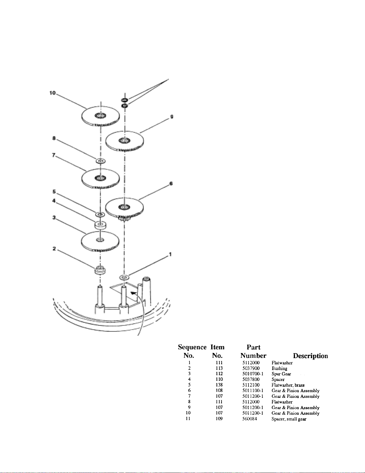
The numbers within circles on this illustration are
g
used
e
g
q
y
sequence-of-assembly numbers; their only function is to indicate which part should be positioned
on the
Item Numbers are used to identify a particular
item by Part Number and Description. The Item
Numbers listed correspond to the Item Numbers
Sequence Numbers 7, 9, and 10 (PN 5011200-1)
are identical spur gears with rather small pinion
ears attached to the bottom side.
Sequence Number 6 (PN 5011100-1) is a spur
gear with a rather long pinion gear attached to the
Sequence Number 3 consists of two (2) spur
gears (PN 5010700-1) "sandwiched" together.
There is no pinion gear on this spur gear.
ear shaft in a particular sequence.
in the Rotator Parts List in the rear of th
PLACE THE OPENING FOR
ELECTRICAL LEADS TO THE
Sequence Numbers 1 and 8 are identical flat
The pinion gears for this application are always
orientated on the shafts with the pinion gear side
"
When assembling the gears and their associated
components on both shafts, follow the numerical
se
"
uence shown.
Figure 14 Spur Gear
Assembl
Page 27

Section 11. Reassembly of the
y
g
p
complete ope
ed.
It is assumed in the following instructions that the
brake mechanism is assembled and operative.
The motor and gear train along with the
potentiometer and the limit switches are likewise
assembled, wired and operative.
It is not likely that the brake wedge will be
exactly positioned in relation to the teeth in the
brake housing to permit proper assembly unless
the brake mechanism is retracted. For this reason,
it is necessary to operate the brake mechanism
electricall
1. See that a small amount of low temperature,
high quality, light weight grease is conservatively distributed around the ball bearings,
ring gear and spur gears. Only an even film
of grease is desirable (approximately one
thimbleful of grease should be used to
lubricate a completely dry rotator).
Excessive grease will only run out during
high temperatures or cause power loss during
2. Rotate the upper spur gear until the inwardly
protruding mechanical stop on the ring gear
touches the channel shaped stop lever. This
action will push it far enough to the left to
just open the left hand limit switch contact (it
is assumed that the rotator is viewed from the
side of the limit switch). This situation
represents the extreme clockwise end of
rotation. The potentiometer arm must then be
rotated to itxtreme clockwise position against
3. Secure the upper bell housing upside down
by the mast support in a vise with the open
end of the "V" toward the bench. The boss,
which drives the potentiometer arm that is
located in the bottom part of the housing,
during Step 8 of the assembly of the
4. Clean the inner portion of the housing and
apply a small amount of grease to the ball
race. Then, carefully insert one ball bearing
assembly with the fringed rim up and against
the outer ed
5. Grasp the operating mechanism by the flat
base, steady the ring gear, invert the
mechanism and lower it into the housing. In
doing this, note that the serrated portion of
the potentiometer arm must engage the
driving boss in the housing and that the three
driving bosses on the ring gear must engage
into the mating recesses 'in the top housing.
This situation will result automatically if the
revious instructions have been followed.
6. Clean the exposed bearing race and apply a
film of grease. Then apply the top bearing
7. Clean the brake housing. Lower the brake
housing into place so that the assembly holes
will appriximately line up with the threaded
holes in the bell housing. Do not
mechanically force an exact alignment of
these holes without electrically retracting the
8. Connect control unit pins 1 and 2 only to the
corresponding pins on the rotator while it remains clamped in the vise. Momentarily
operate the "Brake Release". This will permit
the brake housing to freely rotate the exact
alignment of the holes. With the brake
retracted, secure the upper mast support
(bell) to the lower brake housing. Tighten
finger tight. With the brake retracted, tighten
all four (4) bolts in an alternate pattern to
approximately 85 inchpounds of torque.
Recheck the brake to make sure that it
e of the casting.
It is suggested that all eight wires be
connected from the control box while the
rotator is still on the bench and that its
ration be check
Page 28

Section 12. HAM-V Rotator Replacement Parts
p
No. No. Description Qty
101 5137202 Rotator (complete with hardware) ..............................................................1
102 5030400 Support, Upper Mast (bell casting) .............................................................1
103 5136502 Brake Housing (lower casting) ....................................................................1
104 5033501 Bearings, Ball (49 per retainer)..................................................................98
105 5011300 Retainer, Bearing (one per race) .................................................................2
106 5009700 Casting, Brake Support .............................................................................. 1
107 5011200-1 Gear and Pinion (See Figure 13)..................................................................3
108 5011100-1 Gear and Pinion (See Figure 13) .................................................................1
109 560084 Spacer, Small Gear (See Figure 13).............................................................2
110 5112100 Flatwasher, Brass (See Figure 13) ...............................................................2
111 5037800 Spacer (See Figure 13)............,,.................................................................. 1
112 5136101 Gear, Steel Drive..........................................................................................1
113 5010700-1 Gear, Final Spur...........................................................................................2
114 5037900 Bushing ........................................................................................................1
115 5067000 Arm, Pivot....................................................................................................1
116 5123900 Reinforcement, Pivot Arm .......................................................................... 1
117 572264 Rivet, Steel, Cad plated, 1/8 x 3/16 Semi-Tubular ......................................2
118 350885 Washer, Spring Grip, .241 ...........................................................................1
119 5037000 Assembly, Base and Gear Shaft...................................................................1
120 5012200 Mounting Plate and Stud, Motor..................................................................1
121 5031100 Lug, Solder...................................................................................................2
122 5112000 Flatwasher (See Figure 13) ..........................................................................3
123 5105600 Screw, #10-24 x 1/2" thread cutting, Cad.................................................... 6
124 5137600 Motor and Pinion .........................................................................................1
125 5023100 Potentiometer ...............................................................................................1
126 5009900 Solenoid .......................................................................................................1
127 5010000 Pin, Solenoid ................................................................................................1
128 5010101 S
129 5028206 Ring, Solenoid ketaining ............................................................................ 2
130 5011400 Spring, Solenoid Retaining..........................................................................2
131 5009600 Clip, Retracting Spring ............................................................................... 2
132 380828 Wedge, Brake...............................................................................................1
133 5009800 Link, Connecting..........................................................................................1
134 380626 Pin, Connecting Link .................................................................................. 1
135 5011700 Support, Brake Wedge................................................................................ 1
136 5010401 Latch, Brake.................................................................................................1
137 5010600 Pin, Latch .....................................................................................................2
138 5028204 Retainer, Latch Pin.......................................................................................2
139 5010500 Spring, Latch................................................................................................2
140 179894 Mounting Plate.............................................................................................1
141 510680 Screw, #6 x 3/8", torque............................................................................. 2
142 520057 Screw, #6-32 x 3/8", Pan Head ....................................................................2
143 5105700 Screw, #12-24 x 3/4"................................................................................... 4
acer, Solenoid Pin SS.............................................................................. 3
Page 29
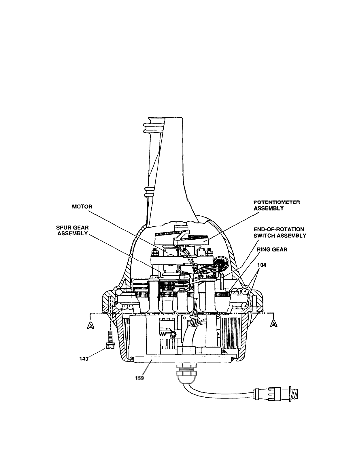
Figure 15 Ins ide View of
Page 30
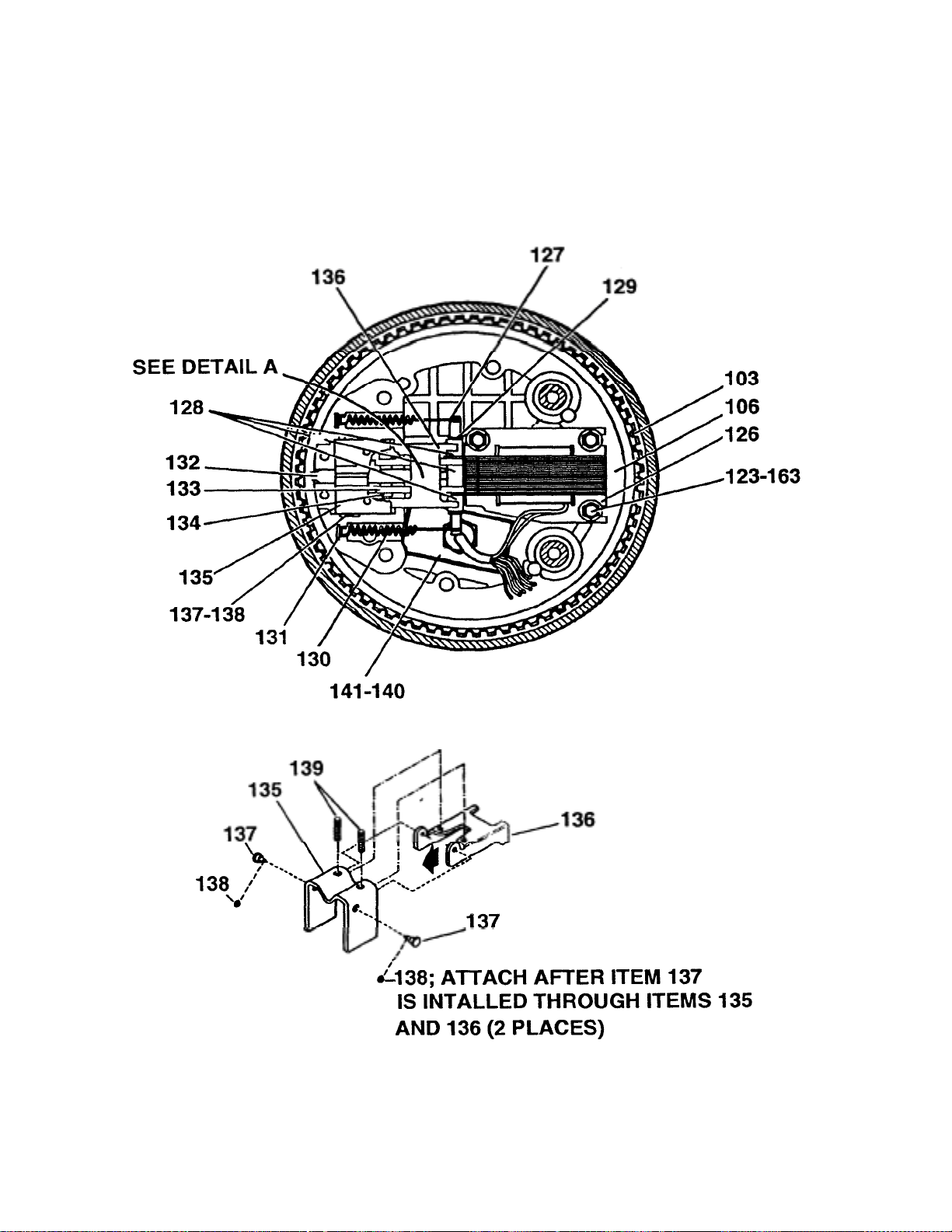
Figure 16 Brake Assembly and Terminal Board
g
Wirin
Detail
-
Page 31

HAM-V Rotator Replacement Parts (continued)
No. No. Description Qty
* 144 5011500 Plate, Mast Clamp ....................................................................................... 1
* 145 5038200 U-Bolt, 1/4"-20,2 1/4" x 3 7/8" ...................................................................3
* 146 5050200 Flatwasher, 5/16" .........................................................................................4
147 110820035 Bolt, 1/4"-20 x 1 1/4", Hex Head.................................................................5
* 148 554099 Nut, 1/4"-20, Hex.........................................................................................5
* 149 561177 Lockwasher, Split, 1/4", SS ........................................................................ 9
150 5008000 Spacer, Switch, Part of Item 164..................................................................8
151 5009100 Bracket, Switch, Part of Item 164................................................................1
152 5112400 Flatwasher, 1/8", Part of Item 164 ...............................................................4
153 5009200 Leaf, Contact, Part of Item 164....................................................................2
154 5011600 Rivet, Contact, Part of Item 1W.................................................................2
155 5009300 Leaf, Contact, Part of Item 164....................................................................2
156 5007601 Disc, Pulsing ............................................................................................... 2
157 5008900 Rivet, Contact ..............................................................................................2
158 106004101 Screw, #4-40 x 5/8" Pan Head .....................................................................4
159 5009700 Cover, Bottom..............................................................................................1
160 102720441 Bolt, 1/4"-20 x 2 3/4" Fil. Head...................................................................4
161 567115 Lockwasher, Split, 1/4"............................................................................... 4
162 5112300 Flatwasher, 3/8" ...........................................................................................3
163 5112200 Flatwasher,.203" ID,. 5" OD .....................................................................4
164 5146110 Assembly, End of Rotation ..........................................................................1
165 567135 Lockwasher, Int. #8......................................................................................3
166 556990 Nut, Hex #8-32.............................................................................................4
167 5104700 Lockwasher, Int./Ext. Tooth, #8 ..................................................................1
168 120006001 Lockwasher, External, #6........................................................................ .... 2
169 5113100 Nut, Hex, #6-32............................................................................................2
170 5030400 Support, Upper Mast....................................................................................1
171 450590 Strain Relief ..................................................................................................1
172 610215 Cable, 8 conductor .............................................................................1.67 ft.
173 650179 Receptacle, 9 pin..........................................................................................1
174 650291 Contact pin ...................................................................................................8
175 650180 Receptacle shell............................................................................................1
870598 Parts Pack, Connector .................................................................................1
*Contained in Mounting Hardware Kit PN
Page 32
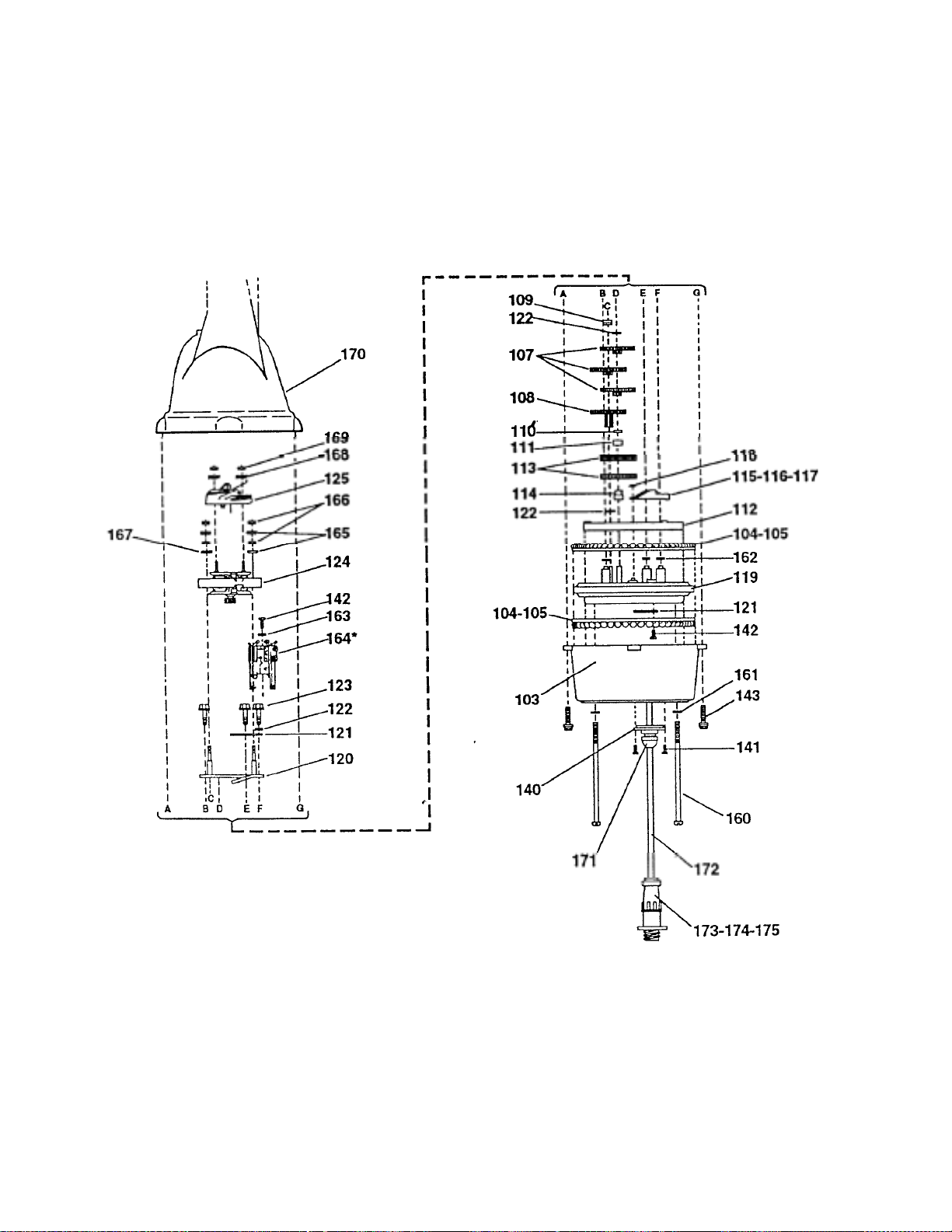
Figure 17 HAM-V Rotator - Illustrated Parts
-
Page 33
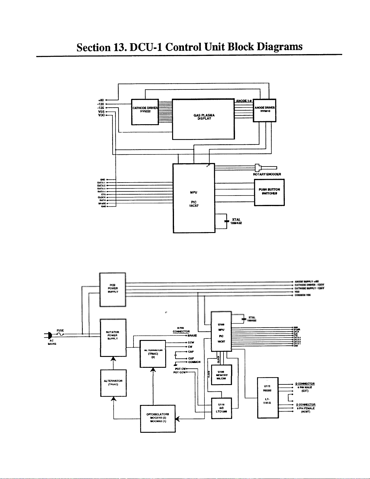
p
Figure 18 Front
Panel PCB
Figure 19 Control PCB and Externl
Com
onents
Page 34

Item
p
)
Section 14. DCU-1 Control Unit Replacement Parts List
No. Description Qty
870804 DCU-1 Assembly, 120 V............................................................................ 1
870842 DCU-1 Assembly, 220 V............................................................................ 1
1034403 Fuse 3 Am
(710053)
1056300 Fuse Holder (120 VAC).......................................................................... 1
(710054) Fuse Holder 5/20 mm (220
105632051 6-32 x 5/16 screw.....................................................................................2
150078
150624-3 Label, "TELE)C "
171131
350979 Clip, capacitor..........................................................................................1
450431 Strain Relief (120 VAC)...,.:................................................................... 1
(450403)
450433 Hole plug (110 VAC only) .....................................................................1
450614
470677 Backing plate, switch.............................................................................. 3
46002 RD Connector, 2 pin, red............................................................................... 2
47138P2 Contact, connector
500157 Screw, 10-24 x
500326
5022500
506325
5086100 Power Cord (120 VAC) ..........................................................................
(5079800)
5112400 Flat Washer. 128 I.D............................................................................... 1
5113100 Nut, 6-32 hex ..........................................................................................5
5141100 Rotator Housing, Top cover.....................................................................1
5141200 Rotator Housing, bottom cover................................................................1
5151501
5152700 Bumper (rubber feet)...............................................................................
520057 Screw, 6-32 x 3/8", (black)
53432116 Knob.........................................................................................................1
53433015 Knob-cap..................................................................................................1
550029
554071
556960 Nut, 1/4"-20, hex......................................................................................1
567110
567120 Flatwasher, 1/4"
567125 Lockwasher, No. 10, internal...................................................................8
640076
640084 Cable Assembly, 10 wire, 7 inch
640085 Cable Assembly, 6 wire, 7 inch
810138 Key pad, 3 button.....................................................................................3
51401-031 Screw, 4-40 x 1/4", socket head...............................................................3
Fuse 1 AMP 5 x 20 mm (220 VAC)........................................................
Front overlay, printed..............................................................................
Spacer, transformer assy.
Strain Relief (220 VAC) .........................................................................
Filter Display, printed .............................................................................
Screw, 4-40 x
Terminal, solder
Screw, 1/4"-20 x 3/4" ..............................................................................
Power Cord (220 VAC) ..........................................................................
Capacitor 13Q-156 MFD.........................................................................
Wing nut, 1/4"-20,
Nut, 10-24, hex
Lockwasher, 1/4", internal .. .. ..............................................................2
Socket, 8 pin (Part of 870849 Wire Assembly)
3 AG (120 VAC
-
Page 35
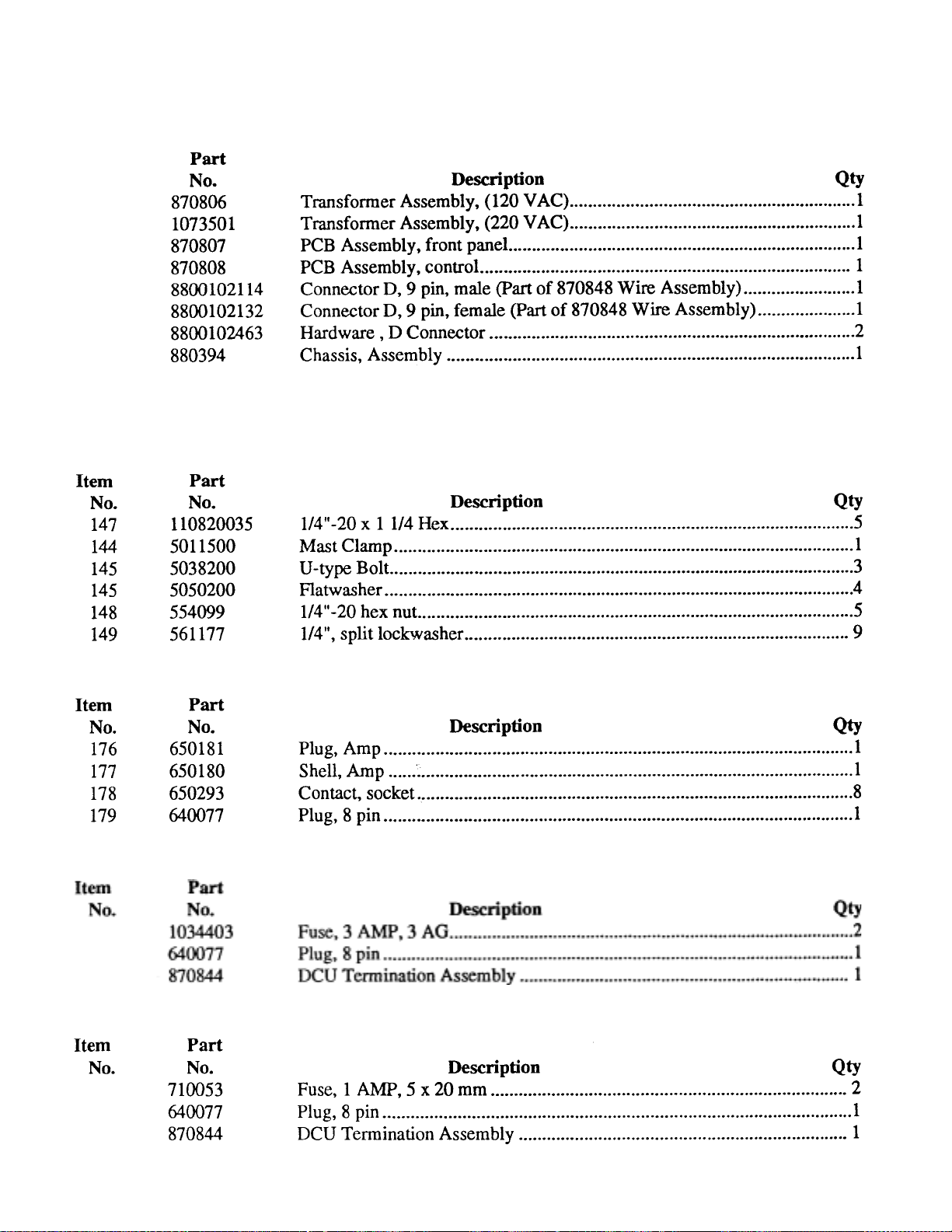
DCU-1 Control Unit Replacement Parts List
,
,
Item
Accessory Kit PN
-
DCU-1 Parts Pack, 120V
DCU-1 Parts Pack, 220V
 Loading...