


ORDER NO. 380S
p
Model 2BDQ-S
Trap Dipole Antenna
INSTRUCTION MANUAL
General Description
The Hy-Gain Model 2BDQ-S is a 1/2
wavelength, dipole antenna for 40 and 80
meters. Band switching is accomplished
automatically through the use of two matched
Hy-Gain 40-m eter Hy-Q t raps. The maximum
overall length is 100' 10 1/2". If the antenna
is mounted in an inverted "V" configuration,
the overall length will be shorte ned.
The balun will improve the performance and
efficiency of the 2BDQ-S. The Hv-Gain
Model BN-86 is a broadband balun designed
specifically for dipole-type antennas. The
balun balances the input impedance to the
antenna and prevents transmission line
radiation.
Theory of Operation
Matched Hy-Gain Hy-Q traps give true 1/2wave resonance. They are tuned at the factory
and no adjustments are necessary. They
operate as a high impedance circuit on 40
meters and add to the overall length of the
antenna as center loading for the 80/75 meter
resonance.
Construction
The Hy-Q traps will withstand h ard wear and
severe weather conditions. All hardware is
passivated stainless steel. The center of the
dipole is supported with a yoke-type center
insulator to which the transmission line
attaches. The ends of th e dipole are suppo rted
by two end insulators constructed of high
impact ABS plastic. The antenna wire is
Alumoweld© #12, which resists rust and has
a breaking strength of 1200 pounds.
SWR and Feedline
The 2BDQ-S antenna is designed for use with
single 50 ohm coaxial feedline. The SWR at
resonance is 1.5:1 or less on both bands.
Alumoweld® is a registered trademark of Copperweld
Bimetallic Grou
Assembly Procedure
g up
d
p
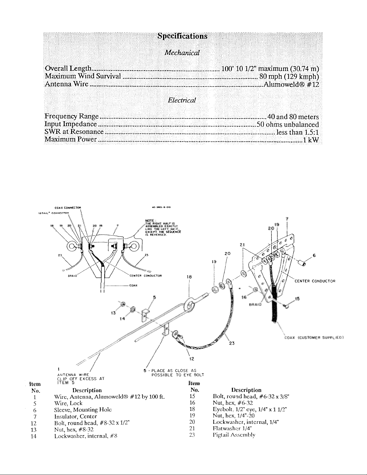
Referring to Figure 1, place one half of the
center insulator (Item No.7) on a flat surface
with the inside facin
.
Assemble the hardware on the eyebolts an
lace in the insulator.
Figure 1 Ass embl y of Antenn a Wi re to Cent er
Insula tor
Strip the coax and s eparate the center condu ctor from the braid. Solder the braid to one
solder lug (Item No. 22) and the center
conductor to the other solder lug. For a
smaller coax , a reducing sleeve is provided.
Apply silicone gr ease or V aselin e®, etc . (not
supplied) to the matin g halves.
Place the halves together and secure them
using the #6-32 x 3/8" bolts and nuts (Item
Nos. 15 & 16).
Hold the eyebolt to keep it from turning and
tighten the 1/4" nuts on the outside, first one
NOTE: Both sides of the antenna are exactly
the same. Each of the following steps must be
done first for one side then repeated for the
other side.
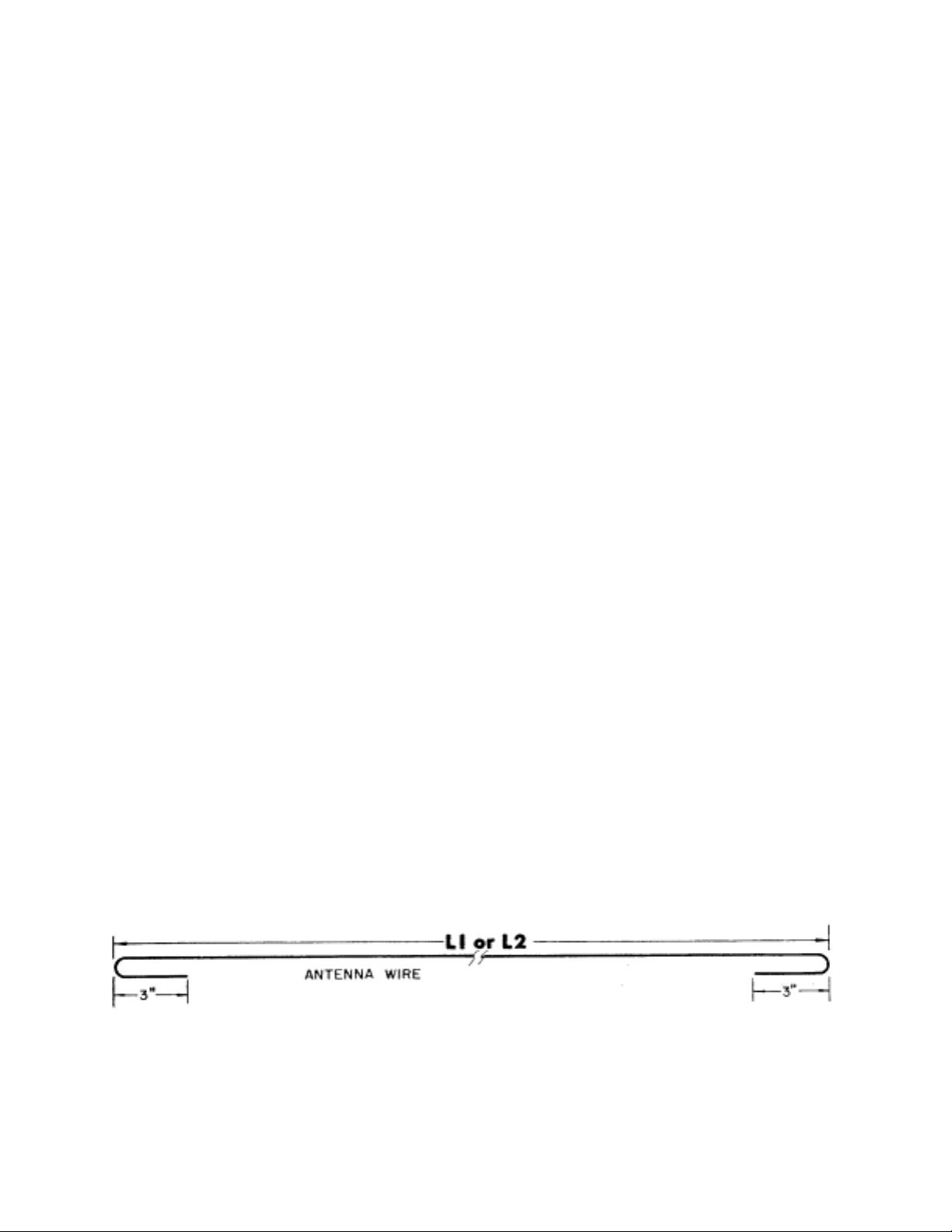
Cut the 40-mete r wire (LI) to eithe r Phone or
Continuous Wave (CW) dimensions as shown
in Figures 2 and 3. Add an extra thr ee inches
on each end for attaching to the center
insulator and 40-meter trap. Example: Ll
length for CW operation is 19' 8 1/4". Add
six inches, three inches each end, which
makes a total length of 20' 2 1/4". Each
insulator or trap requires three inches for
proper attachm ent.
NOTE: When you have selected your mode of
transmission (Phone o r CW), you must us e the
same mode for all dimensions .
Attach one end of the wire (just cut) to the
center insulator (Item No.7) using the wire
locks as shown in Figure 1. Do not forget to
connect th e pigtail to the wire lock.
Clip off all excess wire extendin g past the
wire lock.
Select the 40-meter trap and the trap
connector clamps. Assemble the clamps on
both ends of the trap using the #10-24 x 1
1/2" bolts, lockwashers, and nuts (Item Nos.
9, 11, and 10), as shown in Figure 4.
Carefully remeasure the antenna wire connected to the center insulator and bend the
wire for attachment to the 40-meter trap as
shown in Figures 2 and 3.
Connect the wire to the trap using the wire
locks (Item No. 5) and shown in Figure 4.
Clip off all excess wire extending past the
wire lock.
Figure 2 Antenna Wire
is a registered trademark of Chesebrough -Ponds,
Measurements

NOTE: The end of the trap which has a small bolt must be
m
N
N
p
N
N
N
ps
pointed in the direction of the center insulator as shown in
Figures 3 and 4. This is very important for proper operation
of the antenna.
Use only one bolt on the side of the clamp opposite the
drain holes. An off-center wire attachment is used to keep
the drain holes downward. Remove the twists and kinks
from the wire prior to the installation to insure that the traps
do not rotate in the final mounting position.
Ite Ite
o. Description
4Clam
5 Wire Lock 14 Lockwasher, internal, #8
9 Bolt, hex head, #10-24 x 1 1/2" 17 Bolt, hex head, 1/4"-20 x
10
11 Lockwasher, internal, #10 20 Lockwasher, internal 1/4"
12 Bolt, ro und he a d, #8 -32 x 112"
, Trap Connector 13
ut, hex, #10-24 19
o. Description
ut, hex, #8-32
ut, hex, 1/4" -20
Figure 4 Assembly of the Antenna Wire
to the Tra
Cut the 80-meter antenna wire (L2) to the
length shown for your mode of transmission
(Phone or CW). Do not forget to allow an
extra three i nches on each end for attachm ent
to the 40-meter tr ap and end insul ator.
Bend one end of the wire and attach to the
40meter trap as shown in Figures 2 and 4. Do
not forget to clip off the excess wire
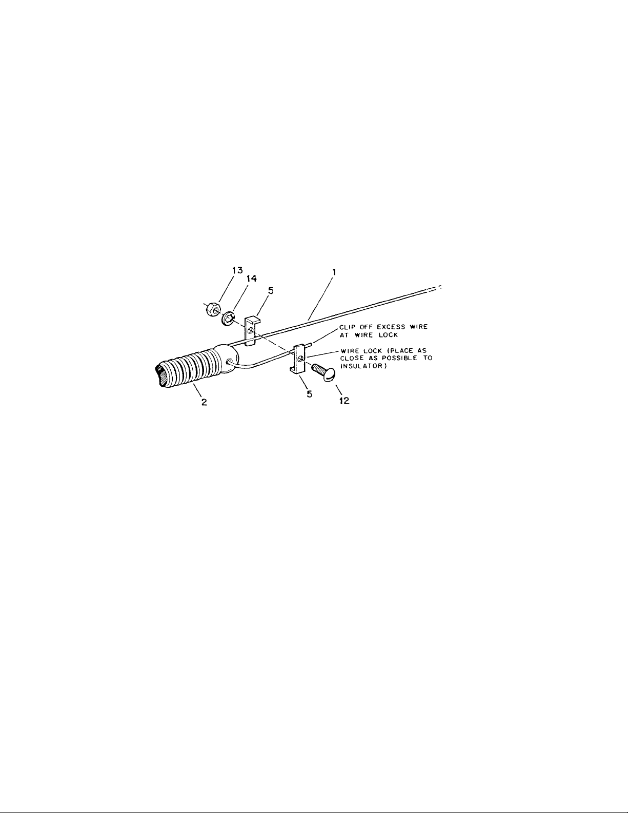
Carefully remeas ure wire and bend for att achment to the end insulator.
Attach the wire to the end insulator as shown
in Figure 5. Clip off all excess wire extending
past the wire lo ck.
Item
No. Description
1 Wire, Antenna, Alumoweld #12 by 100 ft.
2 Insulat o r, End
5 Wire Lock
12 Bolt, round head, #8-32 x 1/2"
Assembly of the Antenna Wire to th e End Insul ator
Mounting
The antenna is now ready to be mounted in
either the horizontal or inverted "V"
configuration. Refer to Figures 6 and 7 for
proper dimensions. When suspending the end
insulators, non-metallic line is preferred. If
you do use «ire, it must be broken up every
six feet with strain insulators to prevent
harmful effects to your radiatio n pattern.
Figure 5
Suspend the antenna by attaching the end insulators to a stable structure. The center insulator may be supported by the antenna itself
or suspended from a support. When
suspending the center insulator from a
support, be sure to keep the insulator from
contacting any of the supporting structure. For
proper operation of this antenna, the center
insulator should be about 46 feet above the
ground. The higher the a ntenna, the better the
operation.

Figure 6 Horizontal
g
g
p
Mountin
Figure 7 Inverted "V "
Mounting
it is extremely important that the antenna be
mounted in the clear. Detrimental effects of
surrounding objects is often underestimated
in the average antenna installation. In
particular, power lines and other metal
objects of considerable length or mass will
deteriorate the performance of any antenna.
When installing the antenna, keep the two
halves balanced with respect to ground and
surrounding objects. Do not attempt to
remove all the sag or tremendous strain will
develop which could cause mechanical
failure. A few feet of sag in the antenna wire
will not harm the performance of the 2BDQ-S
either me chanic ally or electrically.
A Model 2BDQ-S may be mounted in the inverted "V" configuration as shown by the
drawings in this manual. Care must be taken
to insure that the ends of the antenna are at
least 16 feet above the ground. Keep the
antenna balanced. Anything you do to one
end must also be done to the other end or
serious deterioration in performance will
result. One advantage of the inverted "V" is
that you can more nearly match the antenna
impedance to the transmission line impedance. A directional pattern, in the
direction of the slant, will result if angle "A"
(as shown in Fi gure 7) ex ceeds 35 de grees.
VSWR Charts
Figure 8 shows typical SWR curves for this
antenna mounted appr oximately 50 feet above
round.
The optimum heights for this antenna on 40
meters would be between 20 and 30 feet or
greater than 70 feet. The optimum heights for
this antenna on 80 meters would be between
30 and 70 feet. Heights other than these will
roduce SWR in exc ess of 1.5: 1.

Figure S Typical SWR Curves for
this Antenna Installed 50 feet
Above Ground
Hints on Handling Alumoweld© Wire
To meet the numerous re quests for a n on-cor-
rosive, super strength wire, Hy-Gain is now
using Alumoweld© wire in many wire-type
antennas and mounting kits.
Alumoweld© wire meets Military
Specifications for virtually all environmental
conditions. The wire is designed for arcs of
high humidity and salt exposures as well as
other less durable forms of wire but the lasting
properties are far superior. Conducting
properties closely approach that of pure
aluminum making it ideal electrically for RF
use.
There may be some difficulty encountered in
working with the wire due to its tendency to
kink. Kinks may be removed by a pole or
similar stationary curved object and working
the wire b ack an d forth a s shown in Figure 9.
Figure 9 Removing Kinks from
Alumoweld Wire

PARTS LIST
p
,
No. Part No. Description Qt
y
1 691067 Wire, Antenna, Alumowel #12 by 100 ft. .........................1
2 861021 Insulator, End......... ...... ...... ...... ...... ...... ...... ...... ...... ...... ...... ...... ...2
3 877234 Trap Assembly, 40-Meter..........................................................2
877233-1 Parts Pack 380 S, Stai nles s S teel .. .... .... .... .... .... .... .... .... .... .... .... .. 1
4 167236 Clam
, Trap Connector... ...... ...... ...... ...... ...... ..... ....... ...... ...... 8
5 1672 38 Wire Lock... ...... ...... ..... ....... ...... ...... ...... ...... ..... ...... .... ...... ...... 16
6 171586 Sleeve
Mounting Hole...... .... .... .... .... .... .... .... .... .... ... 1
7 465460 Insulator, C ent er. .... .... .... ... ..... .... .... .... .... .... .... ... ..... .... .... .... .... 2
8 465570 Plug, Center Insulator Adaptor............................................ 1
9 500159 Bolt, hex head, #10-24 x 11/2 "... ...... ...... ...... .... ....... ...... .......8
10 55 4071 Nut, hex, # 10-24 ………….. ...... ...... ...... ...... ...... ...... ...... ...... ..... 8
11 565697 Lock-washer, internal, #10 .................................................,.. 8
12 50 0185 Bolt, rou nd h ead , #8 -32 x 1/ 2".. .... .... .... .... .... .... .... ..., .... .„. .... 8
13 550063 Nut, hex, #8-32...... ...... ...... ...... ...... ...... ...... ...... ...... ...... ...... .....8
14 560035 Lockwasher, internal, #8.......... ...... ...... ...... ...... ...... ...... ....,..„ 8
15 501118 Bolt, round head, #6-32 x 3 /8".. .... .... .... .... .... .... .... .... .... ...,..14
16 55 5888 Nut, hex, #6 -32.. .... .... ... ..... .... .... .... .... .... .... .... .... .... .... .... .... ...1 4
17 50 5266 Bolt, hex head , 1/4" -20 x 3/4 "...... ...... ...... ...... ....., ...,.. ...... ,.„„. 4
18 540066 Eyebolt, 1/2" eye, 1/4" x 11/2 ". ...... ...... ...... ...... ...... ...... ...... ....2
19 554099 Nut, hex, 1/4"-20..... ..... ....... ...... .... ...... ...... ...... ...... ..... ...... ...... 14
20 56 2961 Lockwasher, inter nal, 1 /4" .... ...... ...... ...... ...... ...... ...... .,.,.. ..„„ . 8
21 566344 Flatwasher, 1/4".......................................................................4
22 67 7555 Lug, Solder……… ……….. ....... ...... ...... ...... ...... ........ ...... ...... ... 2
23 878466 Pigtail Assembly ..................................................................... 2
Converting American
to Metric
Use this scale to identify lengths of bolts,
diameters of tubes, etc.. The American inch
(1") and foot (1') can be converted to
centimeters in this way.
1 inch (1 ") = 2. 54 c m
1 foot (1') = 30.48 cm
Example
42" x 2.54 = 106.7 cm
 Loading...