

Starkville, MS 39759 USA
NS
UC
ON
NU
(662) 323-9538 FAX: (662) 323-6551
Model AV-14AVQ
Four Bands Vertical Antenna
10, 15, 20, 40 Meter
Ph:
I
General Description Theory of Operation
The Hy-Gain 14AVQ/WB-S is an omnidirectional, self-supporting, vertical radiator that
operates in the 10, 15, 20, and 40 meter
amateur bands. The system will work against
earth ground or a resonant r adial system when
mounted above ground. You can make your
own radial system following the manual, or
use the Hy-Gain 14RMQ Radial System Kit
available at your Hy-Gai n dealer .
The antenna can be used for either Phone or
CW with either a ground or roof mount. It can
also be tuned to mid-band for use with either
Phone or CW. In either case, the SWR band
widths of the antenna are broad enough that
the antenna will operate at an SWR of 2:1 or
less from 10 to 40 meters. T he 14AVQ/WB-S
is supplied with stainless steel hardware and
element clamps for all electrical and most
mechanical con nections .
TR
TI
MA
The use of heavy duty "Hy-Q Traps" pr ovides
automatic band selection. The Hy-Q Traps
are parallel resonant circuits which isolate
the various sections of the antenna and give
quarter wavelength resonance on all bands.
The top hat enhances the broad-band
characteristics of the antenna and permits the
antenna to be short ened b y top loading it.
WARNING
When installing your system, take'
extreme' care t o avoid any accidental
contact with'' power l in e s or overhead
obstructions. F a i l u r e to exercise this
care could result in serious or fatal
injury.
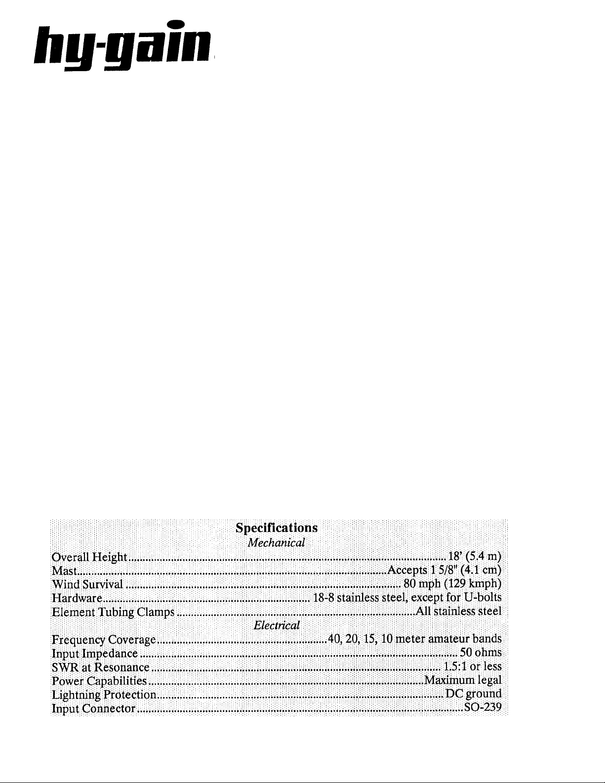
FOR OUR OVERSEAS CUSTOMERS: The
United States used English u nits of measurements. Please see page 12 of this manual for
assistance in identifying the hardware and
components supplied with this product.
AL

NOTE: If the terminals of the input connecto r
are checked wit h an ohmmeter, the y will show
a direct short. This is normal! The matching
coil in the antenna base puts the entire s ystem
at DC ground, but present a perfect 50 ohm
impedance to rf energy
Choosing a Site
The 14AVG/WB-s can be mounted on the
ground, on a rooftop or on a mast. When
mounting the antenna more than three feet
above ground, a resonant radial system must
be used, such as Hy-Gain's 14RMQ Radial
System Kit. If the antenna is roof mounted
and the roof space is too small for a radial
system, you can droop the radials over the
edge of the roof at almost any angle without
seriously changing the performance of the
antenna. The radial system must be insulated
from the roof and connected to a good grou nd
for lightning protection. S ee Figure 5.
For best performance, the 14AVQ/VVB-S
should be ground-mounted clear of building
and other structures. When the antenna is
ground-mounted, a radial system is
sometimes not needed. In most areas, where
soil surface conductivity is poor and a good
ground plane is not possible, lay out ground
radials to improve the efficiency of your
antenna.
Basically, the function of radials is to provide
a low-loss return path for ground currents.
The reason that short radials are sufficient.
when few ar e used, is that at the perimet er of
the circle to which t he grou nd s ystem ex tends,
the radials are sufficiently spread apart. Most
of the return currents are already in the
ground between the radials rather then in the
radials themselv es. As mo re radia ls ar e add ed,
the spaces between them are reduced and
longer lengths help to provide a path for
currents still farther out.
Since the 14AVQ/WB-S is a multi-band,
vertical antenna, the radial system should be
optimized on the lowest frequency you plan
to use. Higher frequencies will benefit
equally from the ground system, while lower
frequencies will not show as much
improvement.
To determine the optimum radial installation
for your 14AVQ/WB-S, you must first decide
what is the limiting factor for your
installation.
1. Cost of radial wi res
2. Land available fo r radials
3. Efficiency of your antenna
Table 1 shows some various ground system
configurations. System A is the least costly
and the least efficient. System F is the most
expensive, takes the most land and i s the most
efficient.
There is no need to make radials exactly 1/4
wavelength long for the 14AVQ/WB-S. In
fact, the onl y case where you should have 1/4
wavelength radials would be for
approximately 90 radials. This differs rather
dramatically from the case of the GroundPlane antenna where resonant radials are
installed above gro und. Since the radials o f a
ground-mounted vertical are actually on, if
not in, the ground, they are coupled by
capacitance or conduc tion to the ground, thus
resonance effects a re not important.
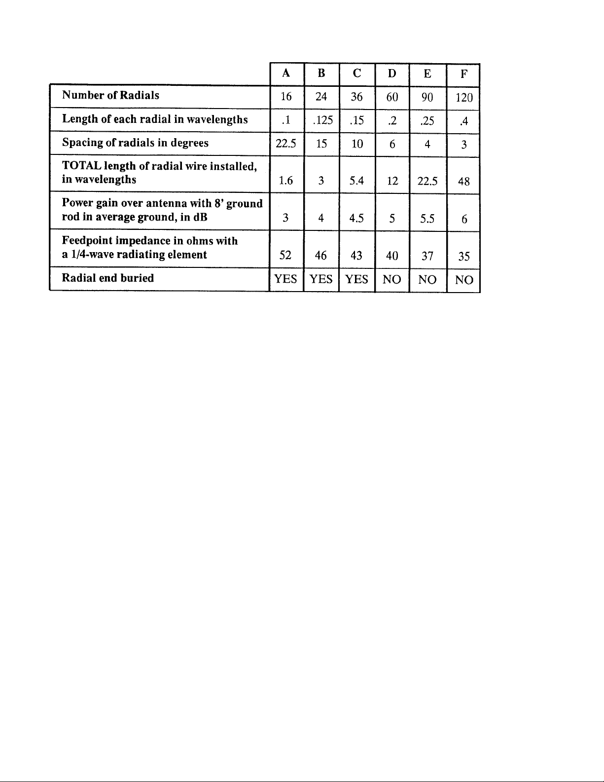
Table 1
y
Optimum Ground System
Configurations
Phase Verticals for
Two or more 14AVQ/WB-S antennas may be
phased together to produce gain or directivity
over one antenna. Refer to the Engineering
Report entitled "Amateur Phasing" included
with this product.
Assembl
Before you begin, read the instructions and
study the illustrations. Compare the parts
against the Parts List.
Decide where to mount your antenna (rooftop
or ground) and what mode of transmission you
will use (Phone, CW or Mid-Band). Take special notice of the dimensions in Figure 1. The
SWR charts will help you decide which
dimensions to choose. See Figure 7.
and Installation

Figure 1 Antenna Assembly
Dimensions
Tubin
g
g
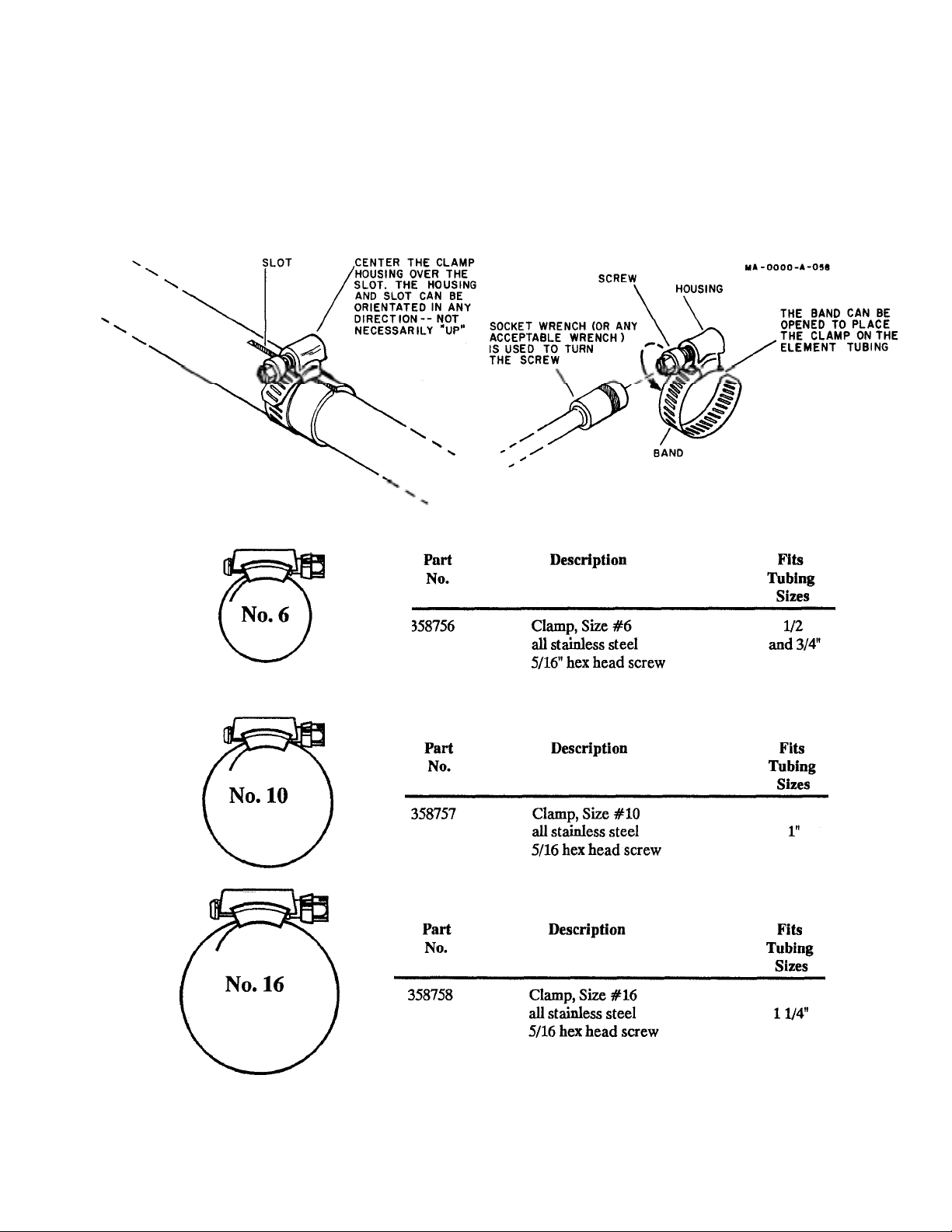
Select the proper size tube cla mps as show n in
the chart. When installing the clamps, place
the clamp near the tub e end w ith the top of the
clamp over the slot in the tube as shown in
Fi
ure 2.
After adjustment of th e tubing leng ths, tighte n
the clamp with a 5/16 inch nut driver, socket,
or open end wrench until the tubing will not
twist or telescope. DO NOT over-tighten!
Figure 2 Tubing
Clamps

CAUTION
y
y
y
)
p
p
All of the antenna dimensions must be set
on the mode chosen - all CW, all midband or all phone. Mixing dimensions in
an attempt to improve another mode on
certain bands will only degrade
performance on all bands.
Refer to Figure 1 in assembling the main portion of the antenna.
M1 and M2 Section
Put a #16 tubing clamp (Item No. 18), untightened, over the M1 section (Item No.
4)(the base is attached to it alread y). Slip the 1
1/8" x 52" M2 section (Item No. 7) into the
top of the M1 and set the M2 at di mens ion ' A',
as shown in Figure 1. Slide the clamp into
place around the top of the M1 and tighten it
just enough to keep the M2 fro m skipping. It
will be full
tightened later.
15-Meter Trap and M3
Section Assembl
Place two, untightened #10 tubing clamps
(Item No. 17) over the 1" x 8" long M3 section
(Item No. 8). Slide the M3 section part way
over the upper end of the 10-meter trap, then
slide the lower end of the 15-meter trap (Item
No. 14) into the M3 section. Set dimension
"C", as shown in Figure 1, and locate the M3
so that it is equally spaced between the two
traps.
Tighten the clamps arou nd the ends of the M3
just enough to keep parts f rom slipping. They
will be fully tightened later.
20-Meter Trap and M4
Section Assembl
Assemble these two pa rts like you did the M3
and the 15-meter trap. Use two more #10
tubing clamps, the 1" x 6 1/2" long M4 section
(Item No. 9) and the 20-meter trap (Item No .
15
.
10-Meter Tra
Put an untightened #10 Tubing clamp (Item
No. 17) over the M2 section, then slip the 10
meter trap (Item No. 11), bot tom f irst, int o the
M2 section. (There is a plastic cover on the
top of all three parts.) Set the trap at
dimension "C", as sh own in Figure 1. Slip the
clamp into place around the top of the M2
section and tighten it just enough to keep the
trap from slipping. It will be fully tightened
later.
NOTE: There is a thread ed metal insert in one
end of the M5 section which will accept the
#10-24 x 1" bolt (Item No. 20), which will
hold the top hat in place. The end with the
insert must be at the to
.
M5 Section
Put a #6 tubing clamp (Item No. 16), untightened, over the swaged end of the 20meter trap. Slip the 7/16" x 56" long M5
section (Item No. 10) into th e swaged end of
the trap and set dimension "E", as shown in
Figure 1. Slide the cl amp in place around the
top of the swaged end of the trap tube and
tighten it just enough to keep the M5 from
slipping. It will be fully tightened later.

Top Hat
p
p
g
(
p
Refer to Figure 3, Radial Top Hat Assembly,
in assembling the Top Hat
Push a 1/8" caplug (Item No. 19) on the end of
each to
radial (Item No. 1).
-
-
-
Installing the Antenna
Refer to the mounting details in Figure 4 and
5 to install the com
leted antenna.
-
-
-
Figure 3 Radial Top Hat
Assembly
Use the following pieces of hardware to att ach
the three radial wires on the M5 section.
Ti
hten securely.
Bolt, hex #10-24 x 1" (Item No. 20) ...........1
Flatwashers, #10 (Item No. 22) ..................4
Lockwasher, internal, #10 (Item No. 21) ..1
Recheck all dimensions. Tighten all of the
ression clamps securely in place.
com
Figure 4 Mounting
Assembly
First mount the completed antenna on your
mast (not supplied) a s shown in Fi gure 4. Us e
the two U-bolts, 5/16" nuts and 5/16" lockwashers
Items Nos. 29,31 and 30).
Use three (3) 1/4"-20 x 3/4" bolts, nuts and
lockwashers (Item Nos 24, 27 & 26) to attach
the insulator to the u pper end of the mounting
 Loading...