

Page 1

Operator's Manual
WG4815E/968999120
WG3613E/968999117
WG3613BF/968999365
WG3613EC/968999756
Please read the operator’s manual carefully and make sure
you understand the instructions before using the machine.
English
Page 2

©2008 HTC. All rights reserved.
Beatrice, NE. Printed in U.S.A.
Page 3

CONTENTS
INTRODUCTION ...............................................................5
Congratulations...........................................................5
General
Driving and Transport on Public Roads
Operating
Good Service
SyMBOlS AND DECAlS .................................................7
SAFETy ............................................................................9
General Operation
Personal Safety Equipment
Slope Operation
Safe Handling of Gasoline
General Maintenance
Transport
CONTROlS ....................................................................16
Control locations ......................................................16
Recoil Starter Grip
Ignition Switch...........................................................17
Motion control levers.................................................17
Operator Presence levers........................................18
Gear shift lever
Throttle Control and Choke Control
Neutral Bail
Blade Engagement lever .........................................19
Refueling...................................................................19
Fuel Shut-off Valve
Accessories
Fuel Tank
Before Starting
Starting the Engine
OPERATION ...................................................................23
Gearbox
Running
Reverse
Operating on hills
Mowing Tips
Stopping....................................................................28
Manual Transport
Cutting Height Adjustment
Cutting Height Table
.......................................................................5
......................5
....................................................................5
..............................................................6
......................................................9
...................................... 11
........................................................ 11
........................................13
...............................................14
..................................................................15
....................................................17
.........................................................18
..........................18
...............................................................19
Parking Brake
..............................................................20
.................................................................. 20
....................................................................25
....................................................................25
....................................................................26
Emergency stop
Normal operating stop
Stopping the Engine
.................................................19
...................................................19
..........................................................21
...................................................22
......................................................26
.............................................................27
..............................................28
....................................28
.......................................28
......................................................29
........................................30
.................................................31
MAINTENANCE ..............................................................32
Maintenance Schedule
Ignition System
Safety System...........................................................35
Function Check
Engine Cooling Air Intake
Throttle and Choke Cable
Air Filter Maintenance
Replacing the Fuel Filter
Tire Pressures
Parking Brake
.......................................................................39
V-belts
Deck belt
Cutting Blades
Blade replacement
Brake Rod Adjustment
Caster Wheels
Cleaning....................................................................41
Hardware
lUBRICATION ................................................................42
lubricating the Cables ..............................................43
Front Wheel Mount
Front Wheel Bearings
Throttle and Choke Cable, lever Bearings.....43
Engine Oil
Engine Oil Filter
Changing the Engine Oil
Engine Oil levels ............................................45
Drive Wheel Idle Arm
Coupling..........................................................46
Mower Deck lever ..........................................46
Rear Wheel
Brake Arms
TROUBlESHOOTING ....................................................48
STORAGE
SCHEMATICS .................................................................51
TECHNICAl DATA ..........................................................52
CONFORMITy CERTIFICATES .....................................55
SERVICE JOURNAl .......................................................56
.......................................................................50
Winter Storage
Service
Torque Specications................................................53
Accessories
Torque Specications................................................54
......................................................................50
.........................................................34
..........................................................38
...........................................................39
..........................................................40
..........................................................41
..................................................................41
.................................................................44
..........................................................50
..............................................................54
.............................................32
...............................................35
.........................................36
.........................................36
...............................................37
...........................................38
.........................................................39
..........................................40
..............................................41
.........................................43
.....................................43
..............................................44
.................................44
......................................46
.....................................................47
.....................................................47
Page 4

WARNING!
Failure to follow cautious operating practices can result in serious injury to the
operator or other persons. The owner must understand these instructions, and
must allow only trained persons who understand these instructions to operate the
mower.
Each person operating the mower must be of sound mind and body and must not
be under the inuence of any mind altering substance.
WARNING!
Engine exhaust, some of its constituents, and certain vehicle components contain or emit
chemicals known to the State of California to cause cancer and birth defects or other
reproductive harm.
Page 5

INTRODUCTION
Congratulations
Thank you for purchasing a Husqvarna Walk-Behind
mower. This machine is built for superior effi ciency
to rapidly mow primarily large areas. A control panel
easily accessible to the operator and a transmission
regulated by steering controls both contribute to the
machine’s performance.
This manual is a valuable document. Read the
contents carefully before using or servicing the
machine. Following the instructions (use, service,
maintenance, etc.) is important for the safety of the
operator and others. It can also considerably increase
the life span of the machine and increase its resale
value.
If you sell your machine, be sure to give the operator’s
manual to the new owner.
The fi nal chapter of this operator’s manual provides a
Service Journal. Ensure that service and repair work
are documented. A well-kept service journal reduces
service costs for the maintenance and affects the
machine’s resale value. Take the operator’s manual
along when the machine is taken to your dealer for
service.
General
In this operator’s manual, left and right, backward and
forward are used in relation to the machine’s normal
driving direction.
Continuous dedication to improve our products require
that specifi cations and design are subject to change
without notice.
Operating
This machine is constructed only for mowing grass
on lawns and even ground without obstacles such
as stones, tree stumps, etc. The machine can also
be used for other tasks when equipped with special
accessories provided by the manufacturer. Operating
instructions for the accessories are provided with
delivery. All other types of uses are incorrect. The
manufacturer’s directions concerning operation,
maintenance, and repairs must be carefully followed.
Lawn mowers and all power equipment, can be
potentially dangerous if used improperly. Safety
requires good judgement, careful use in accordance
with these instructions and common sense.
The machine must only be operated, maintained, and
repaired by persons familiar with the machine’s special
characteristics and who are also knowledgeable about
the safety instructions. Use only approved repair parts
to maintain this machine.
Accident prevention regulations, other general safety
regulations, occupational safety rules, and traffi c
regulations must be followed without fail.
Unauthorized modifi cations to the design of the
machine may absolve the manufacturer from liability
for any resulting personal injury or property damage.
Driving and Transport on Public Roads
Check applicable road traffi c regulations before
transporting on public roads. If the machine is
transported, you must always use approved fastening
equipment and ensure that the machine is well
anchored. DO NOT operate this machine on public
roadways.
Husqvarna-5
Page 6

INTRODUCTION
Good Service
Husqvarna’s products are sold through out the world and only in specialized retail stores with complete service.
This ensures that you as a customer receive only the best support and service. Before the product is delivered,
the machine has, for example, been inspected and adjusted by your retailer. See the certicate in the Service
Journal in this operator’s manual.
When you need spare parts or support in service questions, warranty issues, etc., please consult the following
professional:
This Operator’s Manual belongs to the machine with
the manufacturing number:
Manufacturing Number
The machine’s manufacturing number can be found on the printed plate afxed to the left in the engine
compartment. Stated on the plate, from the top are:
The machine’s type designation (I.D.).•
The manufacturer’s type number (Model).•
The machine’s serial number (Serial no.)•
Please have the type designation and serial number available when ordering spare parts.
The engine’s manufacturing number is stamped on a barcode decal. The decal is placed on the left side of the
crankcase.
The plate states:
•
The engine’s serial number (E/NO).
The engine’s type designation (Code)•
Please have these available when ordering spare parts.
Engine
Transmission
6 - Husqvarna
Page 7
SyMBOlS AND DECAlS
These symbols are found on the machine and in the operator’s manual.
Study them carefully so that you know what they mean.
WARNING!
Xxxx xxxxxx xxxxx xxxx xxxxxxxxx xxxxxx
xxxxxxxxx. xx xxxxxxxx xxxx xxxxxx.
Used in this publication to notify the reader of a risk of personal injury or death, particularly if the reader should
neglect to follow instructions given in the manual.
IMPORTANT INFORMATION
Xxxx xxxxxx xxxxx xxxx xxxxxxxxx xxxxxx
xxxxxxxxx. xx xxxxxxxx xxxx xxxxxx.
Used in this publication to notify the reader of a risk of material damage, particularly if the reader should neglect
to follow instructions given in the manual. Used also when there is a potential for misuse or misassembly.
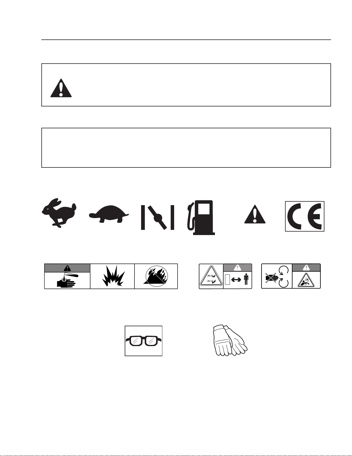
Fast Slow Choke Fuel Warning! CE conformity
marking. Only for
European market
Battery acid is corrosive, explosive and ammable Warning! Rotating blades, Do not touch
keep away from the rotating parts
discharge deck
Use protective glasses Use protective gloves
Husqvarna-7
Page 8
SyMBOlS AND DECAlS
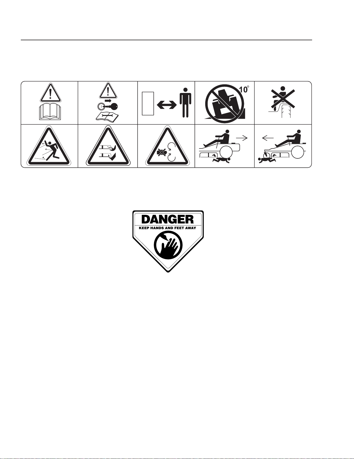
Read Shut off engine and Keep a safe Use on slopes No passengers
Operator’s remove key before distance from no greater
Manual performing any the machine than 10°
maintenance or repair work
Whole body Severing of ngers Do not open or Careful backing up, Careful going
exposure to and toes remove safety watch for other forward, watch for
thrown objects shields while people other people
engine is running
8 - Husqvarna
Moving sharp blades under cover
Page 9

SAFETy
WARNING!
THIS CUTTING MACHINE IS
CAPABLE OF AMPUTATING
HANDS AND FEET AND
THROWING OBJECTS. FAILURE
TO OBSERVE THE FOLLOWING
SAFETY INSTRUCTIONS COULD
RESULT IN SERIOUS INJURY OR
DEATH.
These instructions are for your safety. Read them
carefully.
General Operation
Read, understand, and follow all instructions •
on the machine and in the manual before
starting.
Do not put hands or feet near rotating parts •
or under the machine. Keep clear of the
discharge opening at all times.
Clear the area of objects such as rocks, toys, •
wire, etc., which could be picked up and
thrown by the blades.
Be sure the area is clear of bystanders •
before operating. Stop machine if anyone
enters the area.
Always look down and behind during reverse •
maneuvers. look for both large and small
obstacles.
Never direct discharged material toward •
anyone. Avoid discharging material against
a wall or obstruction. Material may ricochet
back toward the operator. Stop the blades
when crossing gravel surfaces.
Do not operate machine without the entire •
grass catcher, discharge guard, or other
safety devices in place and working
Slow down before turning.•
Never leave a running machine unattended. •
Disengage blades when not mowing. Shut •
off engine and wait for all parts to come to a
complete stop before cleaning the machine,
removing the grass catcher, or unclogging
the discharge chute.
Operate machine only in daylight or good •
articial light.
WARNING!
This symbol means that important
safety instructions need to be
emphasized. It concerns your
safety.
8011-630
Read the operator’s manual before starting the machine
8011-631
Clear the area of objects before mowing
Husqvarna-9
Page 10
SAFETy
Do not operate the machine while under the •
inuence of alcohol or drugs.
Watch for trafc when operating near or •
crossing roadways.
Only allow responsible adults, who are •
familiar with the instructions, to operate the
machine.
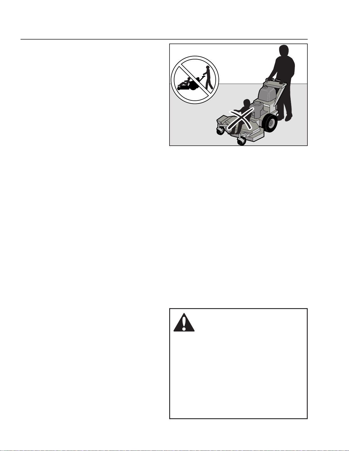
Never take passengers. The machine is only •
intended for use by one person
Use extra care when loading or unloading •
the machine into a trailer or truck.
Always wear eye protection when operating •
machine.
Anyone who operates this machine must rst •
read and understand this Operation Manual.
local laws may regulate the age of the user.
Keep machine free of grass, leaves or other •
debris buildup which can touch hot exhaust
or engine parts and burn. Do not allow the
mower deck to plow leaves or other debris
which can cause buildup to occur. Clean any
oil or fuel spillage before operating or storing
the machine. Allow machine to cool before
storage.
8011-632
Never take passengers
10 - Husqvarna
WARNING!
Engine exhaust and certain
vehicle components contain
or emit chemicals considered
to cause cancer, birth defects,
or other reproductive system
damage. The engine exhaust
contains carbon monoxide,
which is a odorless, colorless,
poisonous gas. Do not use the
machine in enclosed spaces.
Page 11

Personal Safety Equipment
WARNING!
When using the machine, approved personal protective equipment (shown in
illustrations) shall be used. Personal protective equipment cannot eliminate the risk
of injury but it will reduce the degree of injury if an accident does happen. Ask your
retailer for help in choosing the right equipment.
Make sure that you have rst aid equipment •
close at hand when using the machine.
Never use the machine when barefoot. •
Always wear protective shoes or boots,
preferably with steel toe caps.
•
Always wear approved protective glasses or
a full visor when assembling or driving.
Always wear gloves when handling the •
blades.
Never wear loose clothing that can get •
caught in moving parts.
Use ear protectors to avoid damage to •
hearing.
SAFETy
Slope Operation
Slopes are a major factor related to loss of control or
machine tip-over accidents, which can result in severe
injury or death. Operation on all slopes requires extra
caution. If you cannot reverse up the slope or if you
feel unsure, do not mow it.
Mow up and down slopes (10 degrees •
maximum), not across.
Watch for holes, ruts, bumps, rocks, or •
other hidden objects. Uneven terrain could
overturn the machine. Tall grass can hide
obstacles.
Choose a low ground speed so that you will •
not have to stop while on the slope.
Do not mow on wet grass. Tires may lose •
traction.
Avoid starting, stopping, or turning on a •
slope. If the tires lose traction, disengage the
blades and proceed slowly straight down the
slope.
Keep all movement on the slopes slow and •
gradual. Do not make sudden changes in
speed or direction, which could cause the
machine to roll over.
8011-670a
Personal protective equipment
8011-634
Mow up and down, not side to side
WARNING!
Do not drive up or down hills with
slopes greater than 10 degrees.
Do not drive across any slopes.
Husqvarna-11
Page 12
SAFETy
Use extra care while operating machine with •
grass catchers or other attachments; they
can affect the stability of the machine.
Do not use on steep slopes.•
Do not try to stabilize the machine by putting •
your foot on the ground.
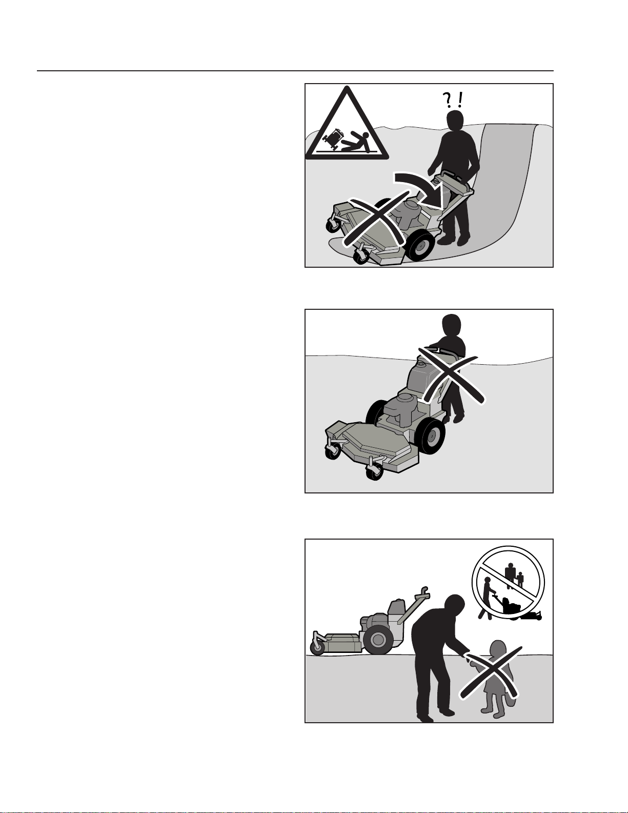
Do not mow near drop-offs, ditches, or •
embankments. The machine could suddenly
roll over if a wheel is over the edge or if the
edge caves in.
Children
Tragic accidents can occur if the operator is not alert to
the presence of children. Children are often attracted
to the machine and the mowing activity. Never assume
that children will remain where you last saw them.
Keep children out of the mowing area and in
•
the watchful care of a responsible adult other
than the operator.
Be alert and turn machine off if a child enters •
the area.
Before and while backing, look behind and •
down for small children.
Never carry children, even with the blades •
shut off. They may fall off and be seriously
injured or interfere with safe machine
operation.
Never allow children to operate the machine.•
Use extra care when approaching blind •
corners, shrubs, trees, or other objects that
may block your view of a child.
8011-635
Be extra cautious when driving on slopes
8011-636
Never allow children to operate the machine
12 - Husqvarna
8011-633
Keep children away from the work area
Page 13
SAFETy
WARNING!
The engine must not be started when the driver’s oor plate or any protective plate
for the mower deck’s drive belt is removed.
Safe Handling of Gasoline
To avoid personal injury or property damage, use
extreme care in handling gasoline. Gasoline is
extremely ammable and the vapors are explosive.
Extinguish all cigarettes, cigars, pipes, and
•
other sources of ignition.
Use only approved gasoline container.•
Never remove gas cap or add fuel with the •
engine running. Allow engine to cool at least
two (2) minutes before refueling.
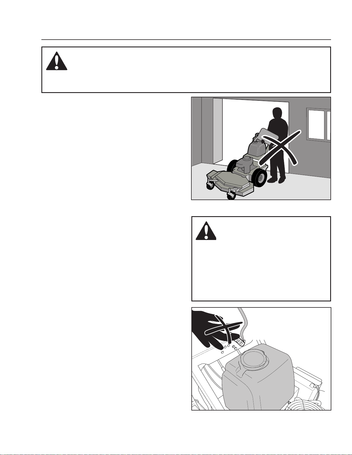
Never fuel the machine indoors.•
Never store the machine or fuel container •
where there is an open ame, spark, or pilot
light such as on a water heater or other
appliance.
Before you begin refueling, minimize the •
risk of static electricity by touching a metal
surface.
Never ll containers inside a vehicle or on a •
truck or trailer bed with plastic liner. Always
place containers on the ground away from
the vehicle when lling.
Remove gas-powered equipment from the •
truck or trailer and refuel it on the ground. If
this is not possible, refuel such equipment
with a portable container, rather than from a
gasoline dispenser nozzle.
Keep the nozzle in contact with the rim of the •
fuel tank or container opening at all times
until fueling is complete. Do not use a nozzle
lock-open device.
If fuel is spilled on clothing, change clothing •
immediately.
Never overll fuel tank. Replace gas cap and •
tighten securely.
Do not start the engine near spilled fuel.•
Never use gasoline as a cleaning agent.•
If leaks arise in fuel system, engine must not •
be started until problem has been resolved.
Check the fuel level before each use and •
leave space for the fuel to expand, as the
heat from the engine and the sun may
otherwise cause the fuel to expand and
overow.
8011-637
Never ll the fuel tank indoors
WARNING!
The engine and the exhaust
system become very hot during
operation.
There is risk for burns if touched.
Allow engine and exhaust system
to cool at least two (2) minutes
before refueling.
8011-777
Do not smoke when using the machine
Husqvarna-13
Page 14
General Maintenance
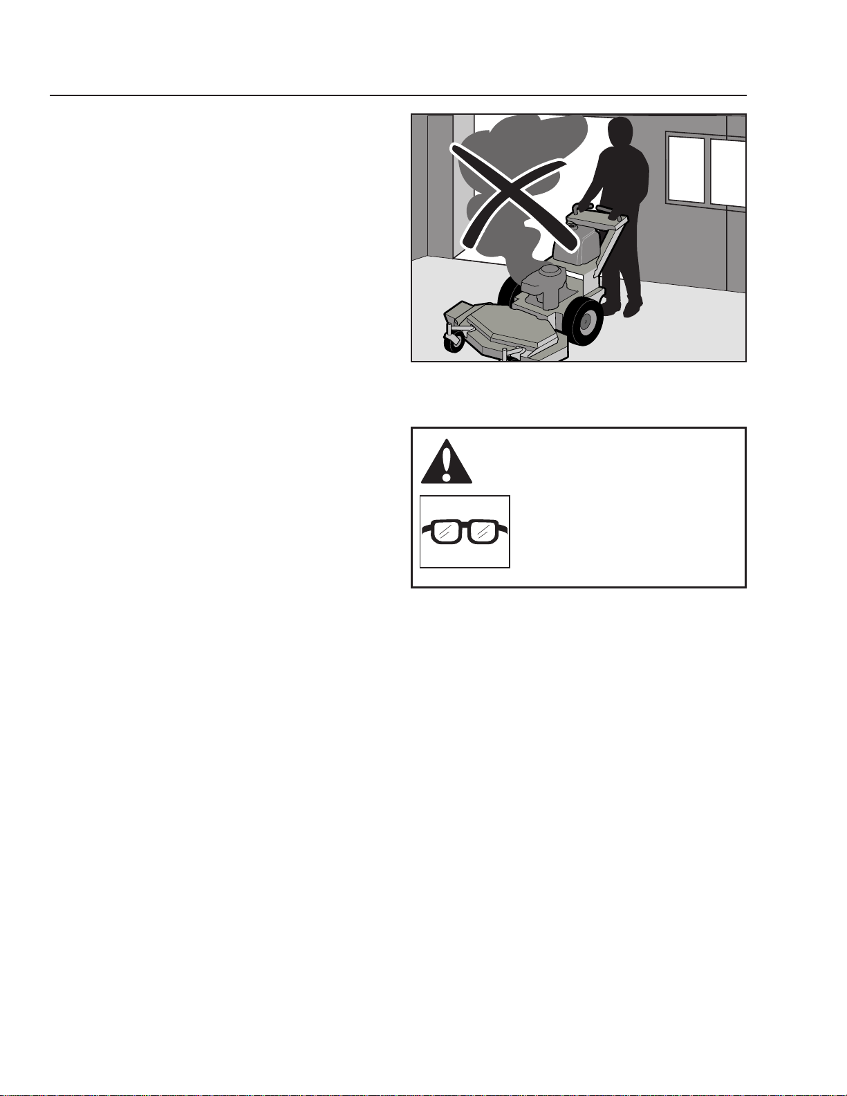
Never operate machine in a closed area.•
Keep all nuts and bolts tight to be sure the •
equipment is in safe working condition.
Never tamper with safety devices. Check •
their proper operation regularly.
Keep machine free of grass, leaves, or other •
debris buildup. Clean oil or fuel spillage
and remove any fuel-soaked debris. Allow
machine to cool before storing.
If you strike a foreign object, stop and •
inspect the machine. Repair, if necessary,
before restarting.
Never make any adjustments or repairs with •
the engine running.
Check grass catcher components and the •
discharge guard frequently and replace with
manufacturer’s recommended parts, when
necessary.
Mower blades are sharp. Wrap the blade or •
wear gloves, and use extra caution when
servicing them.
Check brake operation frequently. Adjust and •
service as required.
Maintain or replace safety and instruction •
labels, as necessary.
Do not modify safety equipment. Check •
regularly to be sure it works properly. The
machine must not be driven with defective
or unmounted protective plates, protective
cowlings, safety switches, or other protective
devices.
Do not change the settings of governors and •
avoid running the engine with overly high
engine speeds. If you run the engine too fast,
you risk damaging the machine components.
Ensure that nuts and bolts, especially the •
fastening bolts for the blade attachments,
are properly tightened, torqued and that the
equipment is in good condition.
Do not modify safety equipment. Check •
regularly to be sure it works properly. The
machine must not be driven with defective
or unmounted protective plates, protective
cowlings, safety switches, or other protective
devices.
Do not change the settings of governors and •
avoid running the engine with overly high
engine speeds. If you run the engine too fast,
you risk damaging the machine components.
SAFETy
8011-638
Never drive the machine in an enclosed space
WARNING!
Use protective glasses for
maintenance work.
14 - Husqvarna
Page 15
SAFETy
Use protective goggles.•
Ensure that the fuel ller cap is mounted •
tightly and no ammable substances are
stored in an open vessel.
Never use the machine indoors or in spaces •
lacking proper ventilation. The exhaust
fumes contain carbon monoxide, an
odorless, poisonous, and lethal gas.
Stop and inspect the equipment if you run •
over or into anything. If necessary, make
repairs before starting.
Never make adjustments with the engine •
running.
The machine is tested and approved only •
with the equipment originally provided or
recommended by the manufacturer. Only use
approved repair parts for the machine.
The blades are sharp and can cause •
cuts and gashes. Wrap the blades or use
protective gloves when handling them.
The mulch blades should only be used in •
familiar areas when higher quality mowing is
desired.
Reduce the risk of re by removing grass, •
leaves, and other debris that may have
accumulated on the machine. Allow the
machine to cool before putting it in storage.
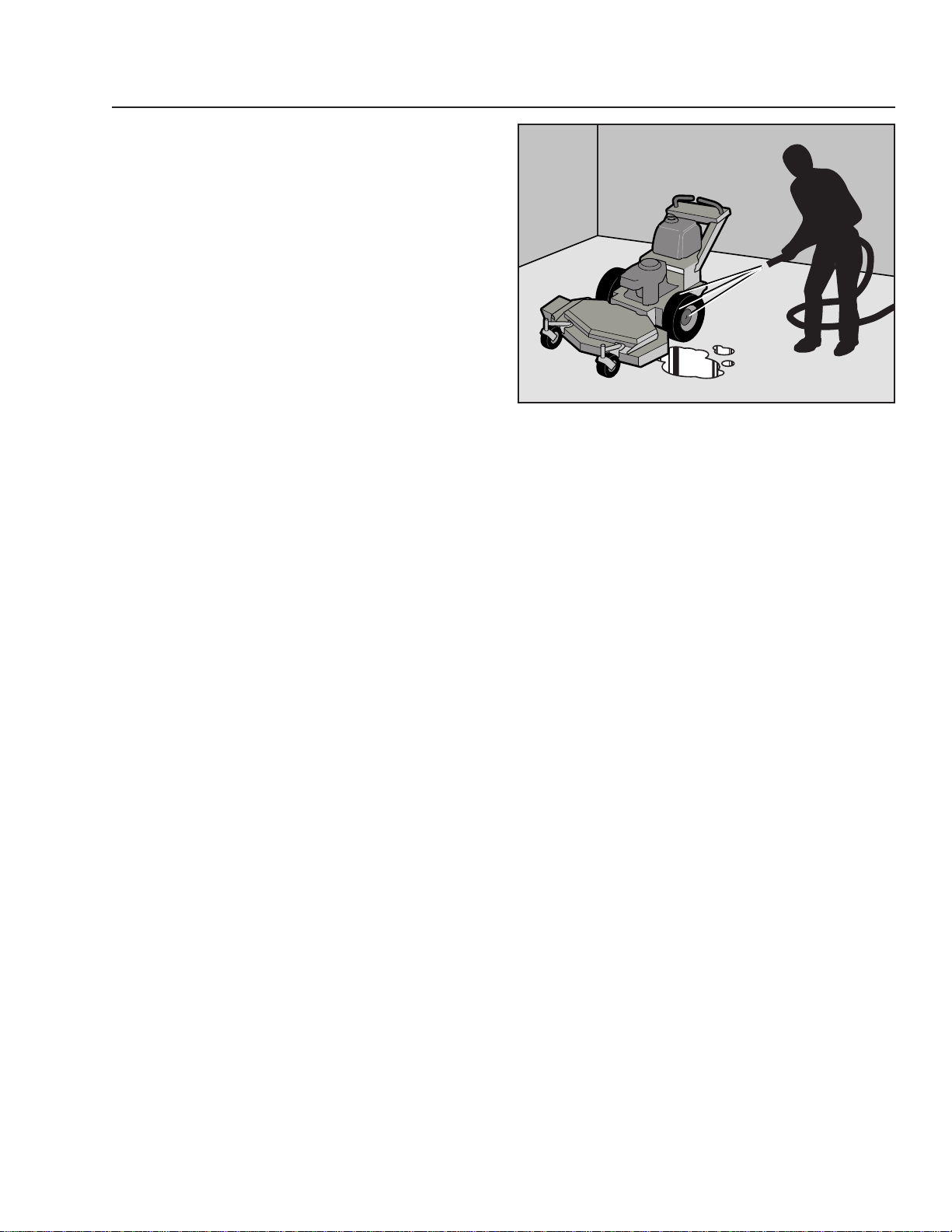
Regularly clean deck and underside of •
deck, avoid spraying engine and electrical
components with water.
8011-639
Clean the machine regularly
Transport
The machine is heavy and can cause serious •
crushing injuries. Be extra cautious when it
is loaded on or unloaded from a vehicle or
trailer.
Use an approved trailer to transport the •
machine. Activate the parking brake, turn off
the fuel supply, and fasten the machine with
approved fastening devices, such as bands,
chains, or straps, when transporting.
Check and abide by local trafc regulations •
before transporting the machine on any road.
Do not tow this machine, it may cause •
damage to the drive system.
Husqvarna-15
Page 16

CONTROlS
This operator’s manual describes the Husqvarna Walk-
Behind Mower. The machine is tted with a Kawasaki
four-stroke overhead valve engine.
Control Locations
Transmission from the engine is made via two V-belts,
one for each wheel. Using the left and right steering
controls, the speed of the rear wheels is regulated for
steering the machine.
3
42
5
6
1
Recoil Starter Grip1.
Ignition Switch2.
Motion Control levers3.
Operator Presence levers4.
Gear Shift lever5.
10
Throttle/Choke Control6.
Neutral Bail7.
Blade Engagement lever8.
Fuel Shut Off Valve 9.
Fuel Cap/Tank10.
789
16 - Husqvarna
Page 17
CONTROlS
Recoil Starter Grip
IMPORTANT INFORMATION
Do not let recoil cord snap back by
itself. This may damage the cord or the
recoil starter assembly.
Pull the recoil starter grip slowly until you feel
compression, then pull it briskly.
Normally this engine will not backre. If you get
backres, contact your Husqvarna dealer for service.
Ignition Switch
The ignition key switch is placed on the control panel.
8011-476
Recoil starter grip
WARNING!
The machine can turn very rapidly
if one steering control is moved
much further forward than the
other.
Motion control levers
The machine’s speed and direction are continuously
variable using the two motion control levers.
When both controls are in the neutral position, the
machine stands still. The controls can be locked in
neutral position by the Neutral bail
By moving both controls an equal amount the machine
moves in a straight line forward.
In order, for example, to turn right while moving
forward, move the right control towards the handle
(neutral position). The rotation of the right wheel is
reduced and the machine turns to the right.
To stop forward travel pull levers back.
8011-475
Ignition key
8011-478
Motion control levers
Husqvarna-17
Page 18

CONTROlS
Operator Presence Levers
located on the handle, the Operator Presence
System levers serve as an additional safety feature.
An electrical interlock safety system is activated
by depressing either one or both of the Operator
Presence levers at the handle grips.
Releasing both Operators Presence levers while
mowing or transporting will break the electrical circuit
and cause the engine and mower to stop. The mower
will not stop immediately after releasing the OP levers
and some travel occurs.
When the blades are engaged or neutral lock bail has
not locked the drive levers, one or both levers must be
pressed against the handle for the engine to remain
running.
Gear shift lever
Gear shift lever has 5 gear speeds. There are also
neutral and reverse gears.
Grip the motion control levers before shifting gears.
This will clutch the gearbox.
8011-478
Motion control levers
Throttle Control and Choke Control
Choke Control
The choke control is used for cold starts to provide the
engine with a richer fuel mixture.
The choke control is combined with the throttle control.
To engage the choke, the throttle control is moved past
the max RPM setting to the choke position.
Do not use the choke when starting a warm engine.
Throttle Control
The throttle control regulates the engine speed and
thereby the rate of rotation of the blades, assuming the
control for engaging the mower deck is pulled forward.
In order to increase or decrease the engine speed, the
control is moved forward or backward respectively.
Avoid idling the engine for long periods, as there is a
risk of the spark plugs fouling.
For best mower performance, USE FUll THROTTlE
WHEN MOWING.
18 - Husqvarna
8011-482
Gear shift lever in the neutral position
8061-682
Choke control/throttle control lever
Page 19
CONTROlS
Neutral Bail
The neutral bail keeps the unit from moving while
idling. The bail will lock the drive levers in neutral
position and must be activated when starting the
engine.
Parking Brake
The parking brake on gear drive machines is applied
when neutral bail is in lock position.
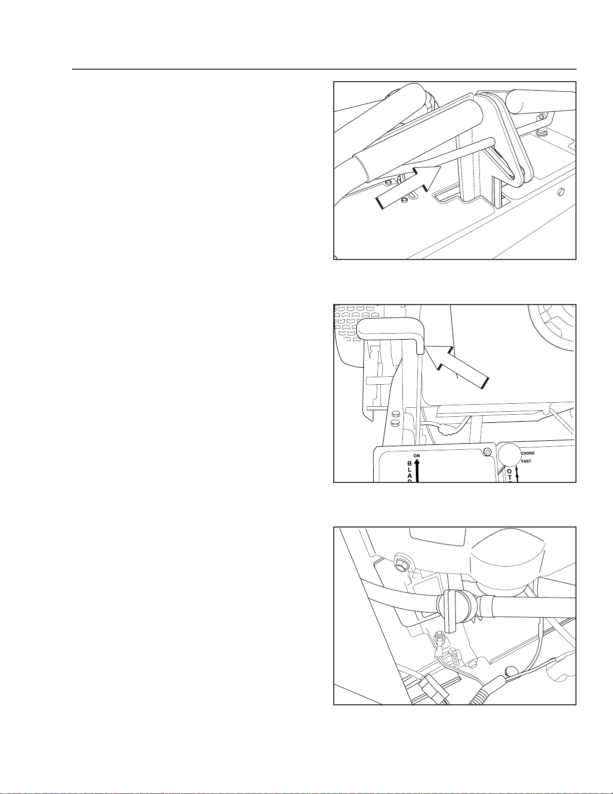
Blade Engagement Lever
The blade engagement lever is on the left support by
the control panel.
In order to engage the blades, push the lever forward.
The blades are disengaged when the lever is pulled
backward.
The blade engagement lever needs to be adjusted so
the lever does not come in contact with control panel
when the lever is in the off position.
8011-477
Neutral bail
Refueling
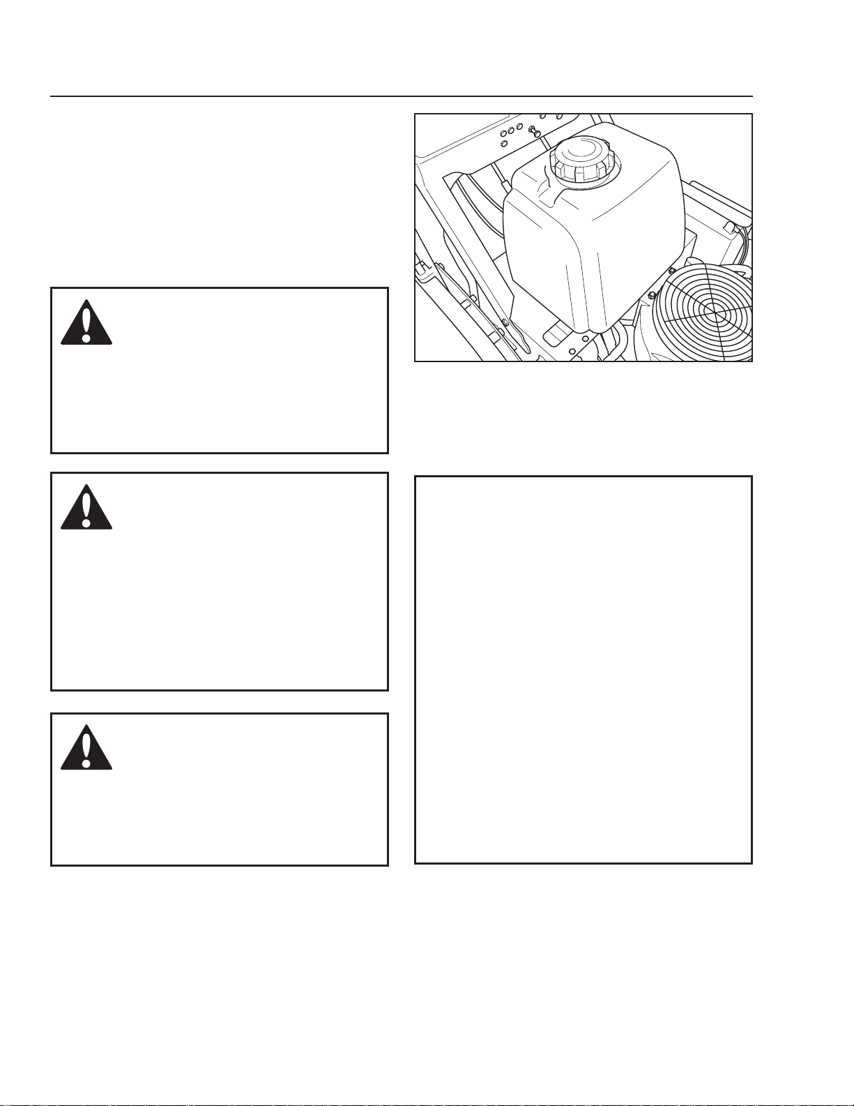
Fuel Shut-off Valve
The fuel shut off valve is placed on the fuel line below
the fuel tank. The valve has two positions; ON and
OFF. The illustration shows the valve in the closed
(OFF) position.
8011-682
Blade engagement lever
8011-437
Fuel shut off valve - closed (OFF)
Husqvarna-19
Page 20
CONTROlS
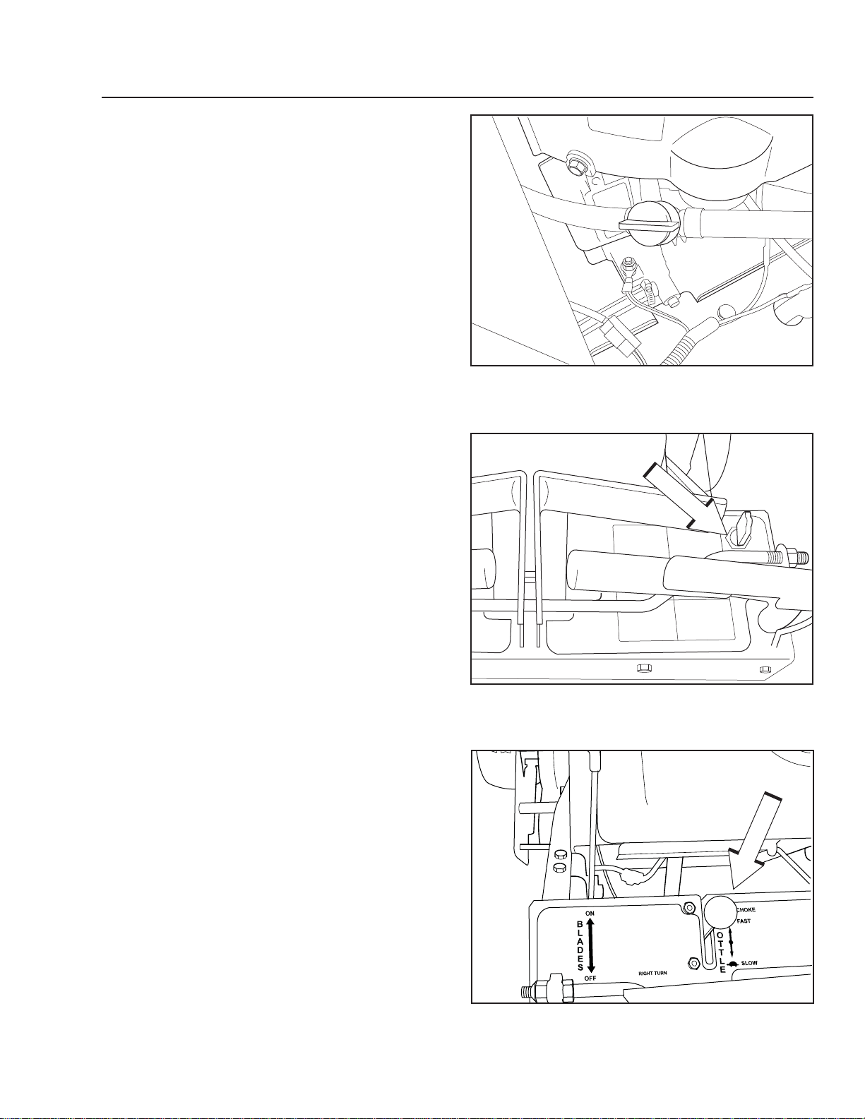
Fuel Tank
The machine has one fuel tank. The tank volume is 5.3
gallons / 20 liters.
The engine should run on a minimum of 87-octane
unleaded gasoline (no oil mix). Also see Technical
Data concerning methanol and ethanol fuels.
When operating in temperatures below 32° F. (0° C.),
use fresh, clean winter grade gasoline to help insure
good cold weather starting.
WARNING!
Gasoline is highly ammable.
Observe caution and ll the
tank outdoors (see the safety
instruction).
8011-418
Fuel tank
WARNING!
The engine and the exhaust
system, become very hot during
operation.
Risk for burns if touched.
Allow engine and exhaust system
to cool at least two (2) minutes
before refueling
WARNING!
Fill to bottom of ller neck. Do not
overll. Wipe off any spilled oil
or fuel. Do not store, spill or use
gasoline near an open ame.
IMPORTANT INFORMATION
Experience indicates that alcohol
blended fuels (called gasohol, ethanol
or methanol) can attract moisture which
leads to separation and formation of
acids during storage. Acidic gas can
damage the fuel system of an engine
while in storage. To avoid engine
problems, the fuel system should be
emptied before storage of 30 days or
longer. Drain the gas tank, start the
engine and let it run until the fuel lines
and carburetor are empty. Use fresh
fuel the next season. See Storage
Instructions for additional information.
Never use engine or carburetor
cleaners in the fuel tank or permanent
damage may occur.
Accessories
For mulching, there is a BioClip attachment available.
This is mounted underneath the mower deck and
consists of control plates and BioClip blades.
20 - Husqvarna
Page 21

OPERATION
Before Starting
Read the sections on Safety and Controls before •
starting the machine.
Perform the daily maintenance before starting (see •
Maintenance Schedule).
Check that there is sufcient fuel in the fuel tank.•
The following conditions must be fullled before the
engine can be started:
The control for engaging the blades must be in •
disengaged position.
WARNING!
Be thoroughly familiar with
control operation and function
before using the mower.
The neutral bail for the motion control levers must •
be in locked position.
WARNING!
Do not operate the mower if the
interlock safety system allows
operation or starting in any
unsafe condition.
8011-474
Disengage blades by pulling lever back
8011-477
Neutral lock bail
Husqvarna-21
Page 22

OPERATION
Starting the Engine
WARNING!
Do not run the engine indoors,
in enclosed or poorly ventilated
spaces. Engine exhaust fumes
contain poisonous carbon
monoxide.
Move blade engagement lever to the OFF position, so
the interlock will allow engine to start.
Check gear shift lever to be sure it is in the neutral
position.
8011-474
Blade engagement lever
While on level terrain, squeeze both motion control
levers and lift up on the neutral bail to lock it into the
neutral lock position. This will ensure that the mower is
braked.
22 - Husqvarna
8011-482
Gear shift lever
8011-477
Neutral bail in the neutral lock position
Page 23
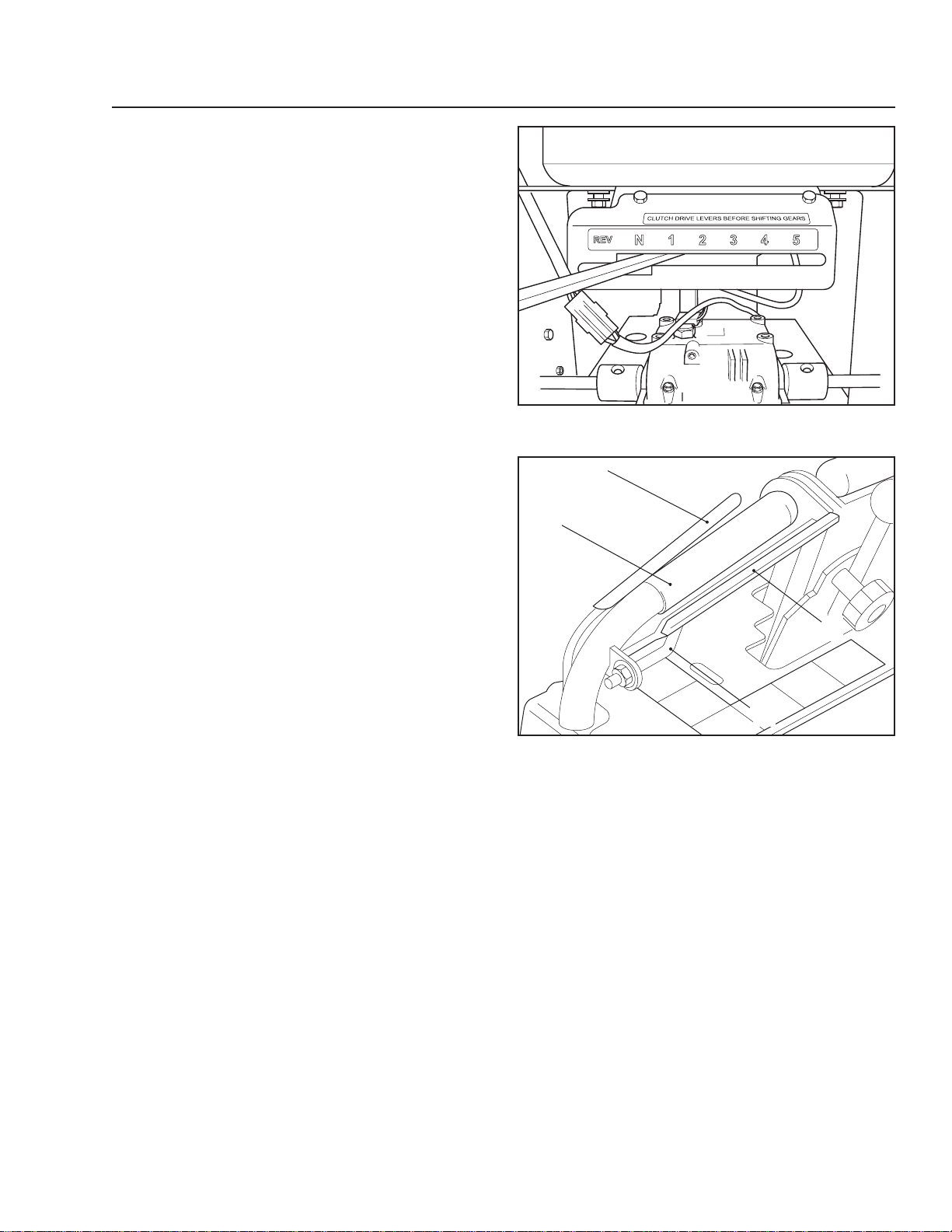
Open fuel shut-off valve.
Turn ignition key to ON position.
OPERATION
8011-438
Fuel shut off valve - open
Set throttle control and engage the choke (if needed).
Do not use choke when the engine is warm.
8011-438
Ignition key
8061-682
Choke control/throttle control lever
Husqvarna-23
Page 24

OPERATION
IMPORTANT INFORMATION
Do not let the recoil cord snap back by
itself. This may damage the cord or the
recoil starter assembly.
Pull the recoil starter grip slowly until you feel
compression, then pull it briskly.
If the engine won’t start in three pulls, open the choke
and try again.
Warm engine momentarily, then disengage the choke
until engine runs smoothly, approximately half throttle.
WARNING!
Be sure all persons are clear of
area before engaging the blades.
8011-476
Recoil starter grip
IMPORTANT INFORMATION
To prolong spindle bearing clutch and
belt life, engage and disengage the
blades at approximately half throttle.
Depress one operator presence lever. Engage the
blades and set the desired rpm. The best cutting
and bagging is obtained with engine at top rpm. Grip
motion control levers before shifting gears.
8011-478
Motion control levers
24 - Husqvarna
8011-474
Blade engaged
Page 25
OPERATION
Gearbox
The gear drive machines have a 5-speed gearbox.
The gear selector is placed under the control panel.
Only shift gear when the machine is standing still and
on level ground.
Running
Depress one operator presence lever and shift 1.
transmission to the desired gear.
Unlock the motion control levers by pushing the 2.
neutral bail down, out of the neutral slots. Slowly
release both levers at the same time to begin
forward motion.
The steering system of this mower uses individual
right and left motion control levers on the handle
bars. Squeezing the lever will reduce tension on
the wheel drive belt, eliminating power to that
wheel. With the opposite wheel still under power, a
turn is accomplished.
If the motion control lever is squeezed even
tighter the brake will be applied to that wheel and
a tighter more abrupt turn is accomplished. Turn
left by squeezing the left hand lever or turn right
by squeezing the right hand lever. If you squeeze
both levers the mower will stop.
8011-482
Gear shift lever
1
4
2
3
1. Operator Presence lever
2. Drive lever
3. Neutral Bail
4. Handle
Handle with bail in neutral position
8011-482
Husqvarna-25
Page 26

OPERATION
Reverse
Depress one operator presence lever and shift
transmission to the reverse gear. Grip motion control
levers before shifting gear.
WARNING!
Do not drive up or down hills with
slopes greater than 10 degrees.
Do not drive across slopes.
Operating on hills
To operate on slopes is a dangerous mowing job.
Read the Safety Instructions section “Driving on
Slopes”.
The slowest speed possible should be used before •
starting up or down hills.
Avoid stopping or changing speed on hills.•
Make all turns slowly.•
8011-482
Gear shift lever
26 - Husqvarna
Page 27

OPERATION
Mowing Tips
Observe and mark rocks and other xed objects in •
order to avoid collisions.
•
Properly level the cutting deck for best mowing
performance. The blades should be parallel to the
ground or slightly tipped down in the front.
Use only sharp blades.•
Check tire pressure. Different pressure can cause •
uneven mowing results.
Use the left hand side of the deck for trimming.•
Drive so clippings are discharged onto the area •
that has been cut. Have the cut area to the
right of the mower. This will result in more even
distribution of clippings and a more uniform cut.
To avoid clippings spraying on roads etc, mow the
rst two patterns in opposite direction.
•
Begin with a high cutting height and reduce it until
the desired mowing result is attained.
Cut the average lawn to 2½" (64 mm) during the •
cool season and to over 3" (76 mm) during the hot
months. For healthier and better looking lawns,
mow often after moderate growth.
For best cutting performance, grass over 15 cm •
(6") in height should be mowed twice. Make the
rst cut relatively high; the second to the desired
height.
Use a high engine speed (the blades rotate •
rapidly) and low speed (the machine moves
slowly) for the best mowing results. If the grass
is not too long and dense, the driving speed can
be increased without noticeably depreciating the
mowing result.
Mowing often for obtaining the nest lawn. The •
mowing becomes more even and the grass
clippings more evenly distributed over the mown
area. The total time taken is not increased as a
higher driving speed can be used without poorer
mowing results.
Avoid mowing wet lawns. The mowing result is •
poorer because the wheels sink into the soft lawn,
clumps build, and the grass clippings will fasten
under the cowling.
Hose the mower deck with water after each use. •
Hose especially underneath. Do not spray high
pressure spray directly on top of spindles. Avoid
getting engine too wet.
8011-409
Mowing pattern
WARNING!
Never drive the machine on
terrain that slopes more than 10
degrees.
Mow slopes up and down, never
side to side. Avoid sudden
directional changes.
Clean mower deck after each use
8011-639-01
Husqvarna-27
Page 28

OPERATION
Stopping
Emergency stop
Release both hands from the operate presence lever
handles. When both operator presence levers return
to their outer position, the engine will quit and the
mower will stop.
OR
Pull both drive levers rmly against handle grips and
hold them securely in place. Use thumbs to lift the
neutral bail up into the neutral slot. Stop engine by
pulling throttle control back and then shut off the key
switch.
Normal operating stop
•
Pull both drive levers (traction levers) rmly toward
the handle grips to stop forward motion.
Use thumbs to lift neutral bail into the neutral slots.•
Move the throttle control to the slow position.•
Move blade engagement control to the off position.•
Move shift lever to the neutral position.•
Stop engine. •
Stopping the Engine
If the engine has been worked hard, allow it to idle a
minute in order to attain normal operating temperature
before stopping it. Avoid idling the engine for longer
periods, as there is a risk of the spark plugs fouling.
When the machine is standing still, set the neutral bail
in the lock position.
Disengage the blades by pulling the blade
engagement lever back.
Move the throttle to the minimum position (tortoise
symbol). Turn the ignition key to the stop position.
8011-477
Neutral bail in the neutral lock position
28 - Husqvarna
8011-474
Blade engaged
Page 29

Remove the ignition key.
IMPORTANT INFORMATION
Close fuel valve at the end of each
mowing session.
Shut OFF the fuel valve.
OPERATION
8011-438
Ignition key
Manual Transport
To move the machine with the engine turned off, make
sure the gear shift lever is in the neutral position and
the motion control levers are not in the locked position.
The locked position is used when the machine is
parked.
8011-437
Fuel shut off valve - closed (OFF)
8011-482
Gear shift lever
Husqvarna-29
Page 30

OPERATION
Cutting Height Adjustment
The cutting height can be adjusted by three methods:
•
Moving spacers between the upper side and
the lower side of the caster swivel according to
“Cutting Height Table”. For instruction, see below.
Moving spacers between the upper side and the •
lower side of the blades according to “Cutting
Height Table”. For removing and installing blades,
refer to “Blade replacement”.
Rear axle height adjustment according to the •
following instruction.
Stop engine and place motion control levers 1.
in the neutral lock position. Remove spark
plug wires.
Remove lower belt shield from underside
2.
of rear deck for better access to axle
adjustment bolts.
loosen axle pivot bolts and axle adjustment 3.
bolts. See illustration.
Place a jack under center of rear deck. 4.
Raise the jack slightly so axle adjustment
bolts may be removed.
With the jack, raise or lower the rear deck 5.
to the desired position using the chart to
ensure proper height.
Reinstall the axle adjustment bolts and 6.
tighten. A tapered punch may be used to
help align the holes.
Using the “Cutting Height Table”, nd the 7.
correct number of spacers to be placed
under the caster swivel.
Remove the lynch pin and washer from the 8.
top of the caster and reposition spacers to
the desired cutting height from the table.
See illustration.
3
1. Axle pivot bolt
2. Securing bolts (loosen each side)
3. Axle adjustment bolts
Rear axle height adjustment
1
3
2
1
2
8011-482
IMPORTANT INFORMATION
It may be necessary to readjust drive
and brake linkages.
IMPORTANT INFORMATION
To achieve the best quality cut, the
blades should be level with the ground
or slightly tipped forward.
30 - Husqvarna
8011-405
1. Machinery bushing
2. Caster swivel
3. Spacers, ½"
Rear axle height adjustment
Page 31

OPERATION
Cutting Height Table
Axle
Position
A 0 4 1½" (38mm)
B 2 4 2½" (64mm)
C 3 4 3¼" (83mm)
D 4 4 3¾" (95mm)
Spacer
Below
Caster Arm
1 4 1¾" (44mm)
3 4 3" (76mm)
4 4 3½" (89mm)
5 4 4" (102mm)
Blade Spacers
Under Cutter
Housing
3 1¾" (44mm)
2 2" (51mm)
1 2¼" (57mm)
0 2½" (64mm)
3 2" (51mm)
2 2¼" (57mm)
1 2½" (64mm)
0 2¾" (70mm)
3 2¾" (70mm)
2 3" (76mm)
1 3¼" (83mm)
0 3½" (89mm)
3 3¼" (83mm)
2 3½" (89mm)
1 3¾" (95mm)
0 4" (102mm)
3 3½" (89mm)
2 3¾" (95mm)
1 4" (102mm)
0 4¼" (108mm)
3 3¾" (95mm)
2 4" (102mm)
1 4¼" (108mm)
0 4½" (114mm)
3 4" (102mm)
2 4¼" (108mm)
1 4½" (114mm)
0 4¾" (121mm)
3 4¼" (108mm)
2 4½" (114mm)
1 4¾" (121mm)
0 5" (127mm)
Cutting
Height
Husqvarna-31
Page 32

MAINTENANCE
Maintenance Schedule
The following is a list of maintenance procedures that must be performed on the machine. For those points not
described in this manual, visit an authorized service workshop. An annual service carried out by an authorized
service workshop is recommended to maintain your machine in the best possible condition and to ensure safe
operation.
Read “Maintenance” in the Safety Instructions section.
1) First change after 5-8 hours. When operating with a heavy load or at high ambient temperatures, replace every 50 hours. 2) In dusty conditions, cleaning and
replacement are required more often.
= Described in this manual
= Not described in this manual
3)
For daily use, the machine should be lubricated twice weekly. 4) Performed by authorized service workshop.
Daily Weekly
Maintenance Before After
Check the parking brake
Check the engine’s oil level (every refueling)
Check the safety system
Check for fuel and oil leakages
Check/clean the engine’s cooling air intake
Check the mower deck
Check for loose hardware (screws, nuts)
Clean under the mower deck
Start the engine and blades, listen for unusual sounds
Check for damage
Thoroughly clean around the engine
Clean around belts, belt pulleys
Check the tire pressures
Check battery
At
Maintenance interval
least
in hours
once
each
year
25 50 100 300
Sharpen/Replace mower blades
2)
(foam)
2)
Clean the engine’s cooling air intake
Clean the air cleaner’s pre-lter
Clean the air cleaner’s lter cartridge 2) (paper lter)
Check/adjust the parking brake
Inspect mufer/Spark arrester
32 - Husqvarna
Page 33

MAINTENANCE
Daily Weekly
Maintenance Before After
Check/adjust throttle and choke cables
Check the condition of belts, belt pulleys
Change the engine oil
1)
Replace the engine oil lter
Clean/replace the spark plugs
Replace the fuel lter
Replace the air lter (paper lter)
2)
Check the caster wheels (every 200 hours)
Replace the air cleaner’s pre-lter
2)
(foam)
Check/adjust the mower deck
Check the engine valve clearance
Perform the 300-hour service
3)
3)
lubricate according to lubrication Schedule
Check hydraulic oil at reservoir
Change hydraulic oil & lter (200 hours)
Clean ns of oil cooler
At
Maintenance interval
least
in hours
once
each
year
25 50 100 300
1)
First change after 5-8 hours. When operating with a heavy load or at high ambient temperatures, replace every 50 hours.
conditions, cleaning and replacement are required more often.
= Described in this manual
= Not described in this manual
3)
Performed by authorized service workshop.
WARNING!
Before performing any service or adjustment checklist
• Turn the ignition switch to “OFF” position and remove the key.
• Make sure the blades and all moving parts have completely stopped.
2)
In dusty
Husqvarna-33
Page 34

MAINTENANCE
Ignition System
The engine is equipped with an electronic ignition
system. Only the spark plugs require maintenance.
For recommended spark plugs, see Technical Data.
1. Remove the ignition cable boot and clean around
the spark plug.
2. Remove the spark plug with a spark plug socket
wrench.
3. Check the spark plug. Replace the spark plug
if fouled, the electrodes are burned or if the
insulation is cracked or damaged. Clean the spark
plug with a steel brush if it is to be reused.
4. Measure the electrode gap with a gapping tool.
The gap should be .030" (0.75 mm). Adjust as
necessary by bending the side electrode.
5. Reinsert the spark plug, turning by hand to avoid
damaging the threads.
6. After the spark plug is seated, tighten it using
a spark plug wrench so that the washer is
compressed. A used spark plug should be turned
1
/8 of a turn from the seated position. A new spark
plug should be turned a ¼ turn from the seated
position.
7. Reconnect the ignition cable.
IMPORTANT INFORMATION
Fitting the wrong spark plug type can
damage the engine.
Inadequately tightened spark plugs
can cause overheating and damage
the engine. Tightening the spark plugs
too hard can damage the threads in the
cylinder head.
Measure the electrode gap
8011-054
34 - Husqvarna
Page 35

MAINTENANCE
Safety System
The machine is equipped with a safety system that
prevents starting or driving under the following
conditions.
The engine can only be started when:
The blades are disengaged. 1.
The neutral bail must be in the locked position.2.
Make daily inspections to ensure that the safety
system works by attempting to start the engine when
one of the conditions is not met.
If the machine starts when one of these conditions
is not met, turn the machine off and repair the safety
system before using the machine again.
Function Check
Check the function of the safety electrical system on a
regular basis.
Engine must stop if blades are engaged without 1.
operator presence levers held down.
Engine must stop if transmission is taken out of 2.
neutral without holding down operator presence
levers.
Engine must not start unless blades are off and 3.
transmission is in the neutral position.
WARNING!
Do not operate the mower if the
interlock safety system allows
operating or starting in any
unsafe condition.
8011-477
Neutral bail in the neutral lock position
Husqvarna-35
Page 36

MAINTENANCE
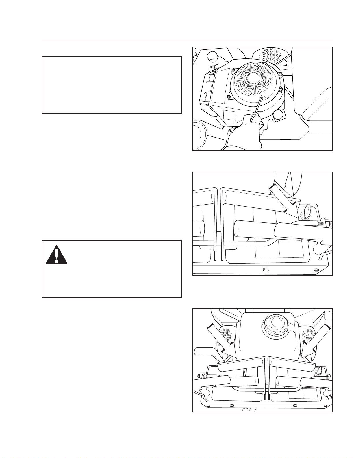
Engine Cooling Air Intake
Check that the engine’s cooling air intake is free from
leaves, grass, and dirt. If the cooling air intake is
clogged, engine cooling deteriorates, which can lead
to engine damage.
Throttle and Choke Cable
Check that the engine responds to throttle increases
and that a good engine speed is attained at full
throttle.
If doubts arise, contact the Husqvarna service
workshop.
If adjustments are necessary, they can be made as
follows for the cable:
loosen the clamping screw for the cable’s outer 1.
casing.
Check that the throttle cable is mounted in the 2.
correct hole in the lever.
Set the throttle lever at full throttle with no choke.3.
Align the hole in the speed control lever with the 4.
hole in the base plate by moving the lever. Insert
a 6 mm dia pin (or a screw) through the two
holes.
Pull up the outer housing of the throttle cable until 5.
the inner wire has almost no slack and tighten the
clamping screw.
Remove the 6 mm pin.6.
Make sure that the carburetor choke valve is 7.
closed completely when the throttle lever is
moved to choke position.
Check engine idle speed.8.
8011-783
Check and clean the cooling air intake
8011-485
Adjusting the throttle cable
36 - Husqvarna
Page 37

MAINTENANCE
Air Filter Maintenance
If the engine seems weak or runs unevenly, the air
lter may be clogged. If run with a dirty air lter, the
spark plugs can become fouled and operation is
disrupted.
It is important to replace the air lter regularly (see the
heading Maintenance Schedule for the proper service
interval).
WARNING!
The engine and the exhaust
system become very hot during
operation. Risk for burns if
touched.
Allow engine and exhaust system
to cool at least two (2) minutes.
To clean/replace the air lter:
Depress the two tabs.1.
Remove the air lter cowling.2.
8011-486
Remove the air lter cowling
IMPORTANT INFORMATION
Do not use compressed air to clean the
air lter.
Do not wash the paper lter.
Do not oil the paper lter.
Remove the paper lter.3.
Tap the paper lter on a solid surface to remove 4.
dust. Replace if dirt cannot be removed.
Remove the foam prelter and clean using a mild 5.
detergent.
Squeeze it dry with a clean cloth.6.
To ret the air lter:
Check that the paper lter is whole. 7.
Mount the pre-lter under the paper lter. Mount 8.
the paper lter in the air lter cowling.
Install the lter cowling on the air lter housing.9.
8011-487
Remove and clean the paper lter
Remove and clean the prelter
8011-488
Husqvarna-37
Page 38

MAINTENANCE
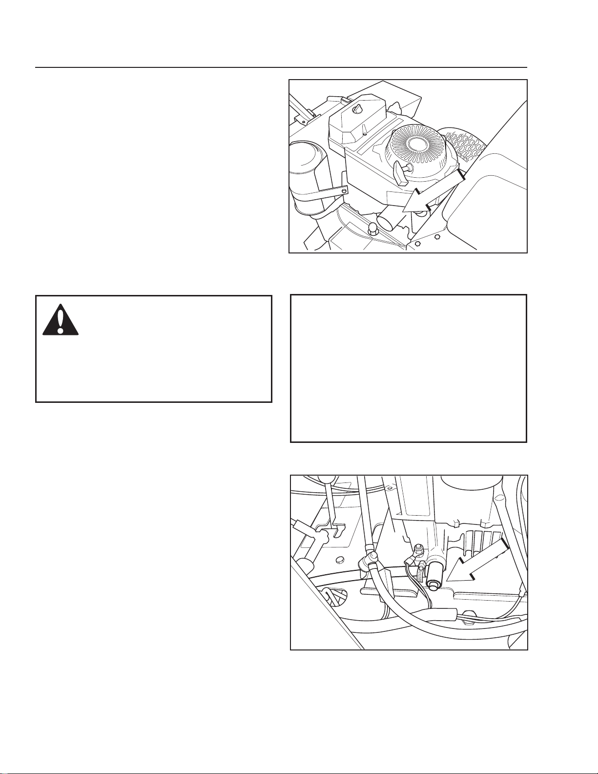
Replacing the Fuel Filter
Replace the line-mounted fuel lter every 100 hours
(once per season) or more regularly if it is clogged.
To replace the lter:
1. Move the hose clamps away from the lter. Use
at-nosed pliers.
2. Pull the lter loose from the hose ends.
3. Push the new lter into the hose ends. Position the
lter with the “FLOW” arrow pointing up toward the
fuel pump. If necessary, a soap solution can be
applied to the lter ends to ease mounting.
4. Move the hose clamps back toward the lter.
Fuel Pump Air Filter
Regularly check that the fuel pump’s air lter is free
from dirt.
Remove the screws and open the pump, no hoses
need be removed.
The lter can be cleaned with a brush if necessary.
Replace the lter on the console.
8011-783
Check and clean the cooling air intake
Tire Pressures
All tires should be at 15 psi / 103 kPa / 1 bar.
38 - Husqvarna
8009-147
Check fuel pump air lter
8011-564
Tire pressures
Page 39
MAINTENANCE
Parking Brake
Visually check that no damage is found on the neutral
bail. Perform a test drive and check that there is
sufcient braking action.
To adjust the handbrake, contact the service workshop
if you are uncertain. Set the neutral bail in the neutral
lock position. Tighten the wing nut. Check if the
machine is braked, if not tighten the wing nut again.
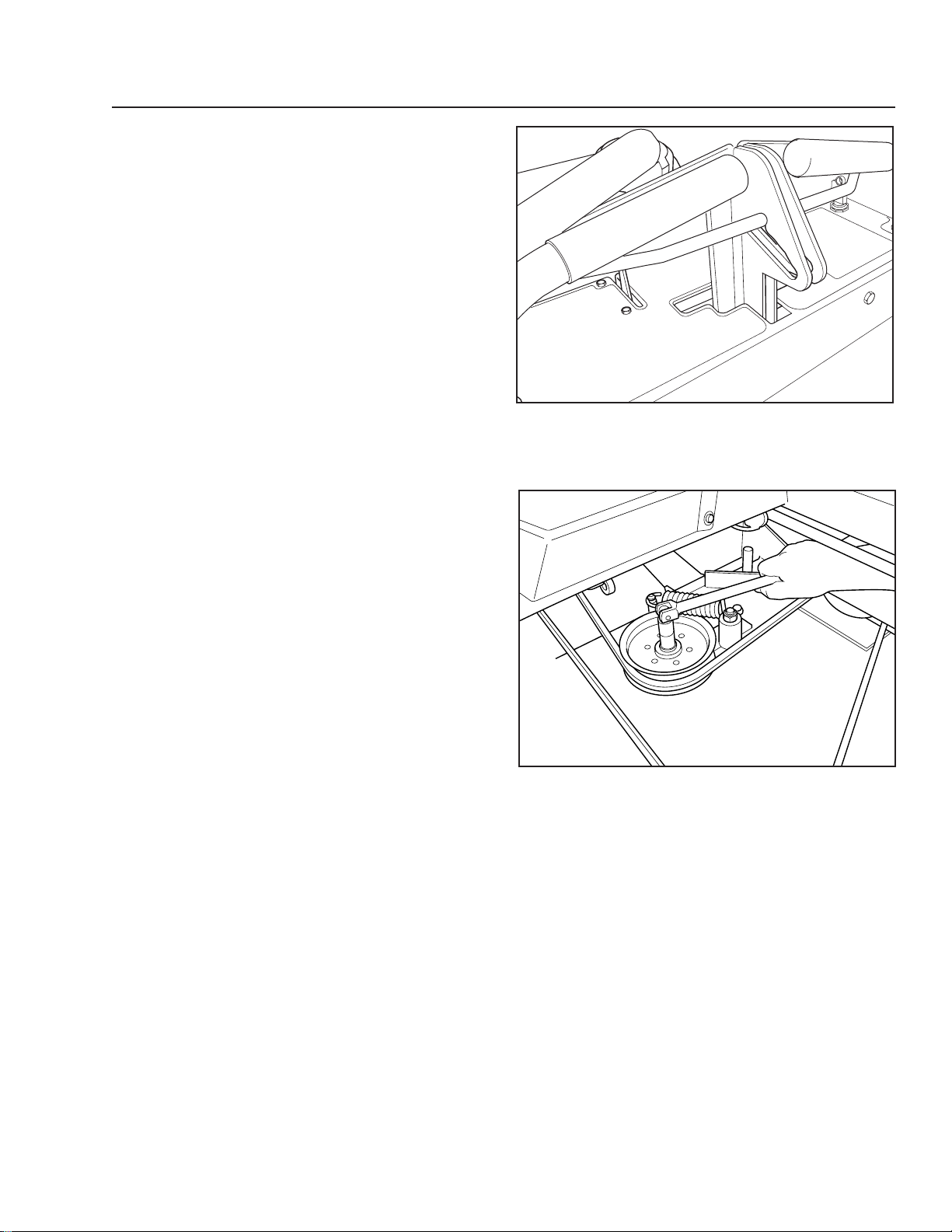
V-belts
Deck belt
Check every 100 hours of operation. Check for severe
cracking and large nicks.
NOTE: The belt will show some small cracks in
normal operation.
To replace belt, set deck to its lowest position.
Remove the plate and belt shields.
Use a ratchet with a 9/16" socket on the spring idler bolt
to relieve the tension on the belt. Slide the belt off the
pulley and fully remove the belt.
Reverse the procedure for installation. See the decal
on the top of deck for belt routing information.
After installation is complete check the belt for twists.
8011-477
Neutral bail in the neutral lock position
8011-775
Slacken the belt tensioner
Husqvarna-39
Page 40

MAINTENANCE
Cutting Blades
WARNING!
Blades are sharp. Protect your
hands with gloves and/or wrap
blades with a heavy cloth when
handling.
To achieve the best mowing effect, the blades must be
well sharpened and not damaged.
Bent or cracked blades or blades with large nicks
should be replaced.
Damaged blades should be replaced when hitting
obstacles that result in a breakdown. let the service
workshop decide whether the blade can be repaired/
ground or must be replaced.
Balance the blades after sharpening.
Check the blade mounts.
8011-604
Check the cutting blades
IMPORTANT INFORMATION
The sharpening of blades should be
carried out by an authorized service
workshop.
Blade replacement
Remove blade bolt by turning counterclockwise.
Install new or resharpened blade with stamped
“GRASS side” facing towards ground/grass (down) or
“THIS SIDE UP” facing deck and cutter housing.
Install and tighten blade bolt securely. Tighten torque
90 ft/lb (122 Nm).
IMPORTANT INFORMATION
Special blade bolt is heat treated.
Replace with a Husqvarna bolt if
required. Do not use lower grade
hardware than specied.
8011-671-4
Blade attachment
40 - Husqvarna
Page 41

MAINTENANCE
Brake Rod Adjustment
The brake rod should be in the lower hole on the brake
arm. Make sure the rod is properly installed.
To increase braking, turn the wing nut down on the
rod. Do not turn the wing nut down too far as this will
result in a constant braking action and will excessively
wear the brake lining and cause premature failure.
Caster Wheels
Check every 200 hours. lift front of unit off of ground
so caster wheels can rotate freely. Tighten caster bolt
then loosen ½ turn. Check that wheel rotates freely. If
wheel does not rotate freely, loosen the caster bolt in
¼ turn increments until wheel rotates freely.
Foam lled tires or solid tires will void the warranty.
8011-774
Brake rod position
Cleaning
Under side of rear deck
Remove grass and debris.
Washing
Regular cleaning and washing, especially under the
mower deck, will increase the machine’s lifespan.
Make it a habit to clean the machine directly after use,
before the dirt sticks. Do not spray high pressure water
directly on the top of the deck.
Hardware
Check daily. Inspect the entire machine for loose or
missing hardware.
8011-619-2
Caster wheel
8011-639-01
Regularly clean deck
Husqvarna-41
Page 42

lUBRICATION
25h1/365 50h1/52 200h 300h100h12/12
12/12 Every year
1/52 Every Week
1/365 Every day
lubricate with grease gun
Filter change
*Change transaxles (transmission) lters.
General
Remove the ignition key to prevent unintentional
movements during lubrication. When lubricating with
an oil can, it must be lled with engine oil.
When lubricating with grease, unless otherwise stated,
use a high grade molybdenum disulphide grease.
For daily use, the machine should be lubricated twice
weekly.
Wipe away excess grease after lubrication.
lubricate with oil can
Oil change
level check
It is important to avoid getting lubricant on the belts
or the drive surfaces on the belt pulleys. Should this
happen, attempt to clean them with spirits. If the belt
continues to slip after cleaning, it must be replaced.
Gasoline or other petroleum products must not be
used to clean belts.
8011-685
42 - Husqvarna
Page 43

lUBRICATION
Lubricating the Cables
If possible, grease both ends of the cables and move
the controls to end stop positions when lubricating.
Ret the rubber covers on the cables after lubrication.
Cables with sheaths will bind if they are not lubricated
regularly. If a cable binds, it can disrupt operation.
If a cable binds, remove the cable and hang it
vertically. lubricate it with light engine oil until the oil
begins to escape from the bottom.
Tip: Fill a small plastic bag with oil and tape it so that
it seals against the sheath and allow the cable to hang
vertically from the bag overnight. If you do not succeed
in lubricating the cable, it must be replaced.
Front Wheel Mount
1.
lubricate with a grease gun, one zerk for each wheel
mount, until the grease is forced out. Use only good
quality bearing grease. Grease from well-known
brand names (petrochemical companies, etc.) usually
maintains a good quality.
Front Wheel Bearings2.
lubricate with a grease gun, one zerk for each set of
wheel bearings, until the grease is forced out. Use only
good quality disulphide grease.
Throttle and Choke Cable, Lever Bearings3.
lubricate the cable ends at the carburetor with the oil
can. Move the controls to the end points and lubricate
again.
The throttle cable is also lubricated at the control when
the control console is removed.
8011-731
Lubricating the front wheels
Choke and throttle cable
8011-485
Husqvarna-43
Page 44
Engine Oil
Engine Oil Filter4.
Drain the engine oil in accordance with the •
work description under the heading Engine
Oil/Change Engine Oil.
Remove the oil lter. If necessary, use a lter •
remover.
Wipe new, clean engine oil onto the seal for •
the new lter.
Mount the lter by hand with +¾ turn.•
Run the engine warm, then check that there •
are no leaks around the oil lter seal.
Check the oil level in the engine, ll •
if necessary. The oil lter holds 0.1 qt
(0.1 liters) of oil.
lUBRICATION
8011-734
Changing the oil lter
WARNING!
Engine oil can be very hot if it is
drained directly after stopping the
engine. Allow the engine to cool
to a safe temperature rst.
Changing the Engine Oil5.
The engine oil should be changed for the rst time
after 8 hours of operation. Thereafter, it should be
changed every 100 hours.
Place the machine on a at surface.•
Place a container under the engine where •
the oil drain valve exits.
Remove the dipstick and open the valve cap. •
Allow the oil to run out into the container.•
Close the oil drain valve cap.•
Replace the oil lter if necessary.•
Fill with new engine oil in accordance with •
Checking the Oil level.
Start the engine. Run it for 3-5 minutes. Stop •
and recheck the oil level.
IMPORTANT INFORMATION
Used engine oil is a health hazard
and must not be disposed of on the
ground or in nature; it should always
be disposed of at a workshop or
appropriate disposal location.
Avoid skin contact; wash with soap and
water in case of spills.
8011-451
Oil drain valve
44 - Husqvarna
Page 45

lUBRICATION
Engine Oil Levels
Check the oil level in the engine when the machine is
standing level and the engine is stopped.
Remove the dipstick, wipe it clean, and then replace it.
The dipstick should not be screwed into place.
Take the dipstick out again and read the oil level.
The oil level should lie between the markings on the
dipstick. If the level is approaching the “ADD” mark, ll
the oil to the “FUll” mark on the dipstick.
Never ll to above the “FULL” mark.
The oil is lled through the hole for the dipstick.
8011-734
Remove the dipstick
Engine oil SAE 30 or SAE10W-30 or alternatively, at
10W-40 class SF-SJ (over +32°F / 0°C).
Over 68°F / +20° SAE 40 can be used.
Use engine oil SAE 5W-20, class SF-SJ (under +32°F
/ 0°C).
The engine holds 1.6 qt (1.7 liters) of oil excluding
the lter, including lter 1.7 qt (1.9 liters).
8009-159
Dipstick markings
8009-159
Dipstick markings
Husqvarna-45
Page 46

lUBRICATION
Drive Wheel Idle Arm6.
lubricate with a grease gun, one zerk for each arm,
until the grease is forced out.
Use only good quality molybdenum disulphide grease.
Grease from well known brand names (petrochemical
companies, etc.) usually maintains a good quality.
Coupling7.
lubricate with a grease gun, one zerk for each
coupling, until the grease is forced out. Use only good
quality molybdenum disulphide grease.
Grease from well-known brand names (petrochemical
companies, etc.) usually maintains a good quality.
8011-495
Lubricating the drive wheel idler arm
Mower Deck Lever8.
lubricate with a grease gun, one zerk for each lever,
until the grease is forced out.
Use only good quality molybdenum disulphide grease.
Grease from well-known brand names (petrochemical
companies, etc.) usually maintains a good quality.
46 - Husqvarna
8011-494
Lubricating the coupling
8011-715
Lubricating the deck lever
Page 47

lUBRICATION
Rear Wheel9.
lubricate with a grease gun, one zerk for each rear
wheel, until the grease is forced out.
Use only good quality molybdenum disulphide grease.
Grease from well-known brand names (petrochemical
companies, etc.) usually maintains a good quality.
Brake Arms10.
lubricate with a grease gun, one zerk for each brake
arm, until the grease is forced out.
Use only good quality molybdenum disulphide grease.
Grease from well-known brand names (petrochemical
companies, etc.) usually maintains a good quality.
8011-716
Lubricating the rear wheel
Lubricating the brake arms
8011-495
Husqvarna-47
Page 48

TROUBlESHOOTING
Problem Cause
The engine will not start. • Mower deck control is engaged.
• Steering controls are not locked in the neutral position.
• Spark plug wire are off.
• Contamination in the carburetor or fuel line.
• Fuel shutoff valve is closed.
• Clogged fuel lter or fuel line.
• Empty fuel tank.
• Ignition system faulty.
The engine runs rough. • Faulty carburetor.
• Choke control is pulled out with a warm engine.
• Clogged fuel lter or jet.
• Clogged ventilation valve on the fuel cap.
• Fuel tank nearly empty.
• Fouled spark plugs.
• Spark plugs are loose.
• Defective ignition cable.
• Defective spark plug electrode.
• Defective spark plug connection.
• Rich fuel mixture or fuel-air mixture.
• Wrong fuel type.
• Water in the fuel.
• Clogged air lter.
The engine seems weak. • Clogged air lter.
• Fouled spark plugs.
• Carburetor incorrectly adjusted.
The machine vibrates.
48 - Husqvarna
• Blades are loose.
• Blades are incorrectly balanced.
• Engine is loose.
Page 49

TROUBlESHOOTING
Problem Cause
The engine overheats.
The machine moves slowly, unevenly. • Drive belt for the transmission slack or has come off.
Mower deck not engaging. • Drive belt for the mower deck has come loose.
Uneven mowing results.
• Clogged air intake.
• Engine overloaded.
• Poor ventilation around engine.
• Defective engine speed regulator.
• Too little or no oil in the engine.
• Fouled spark plugs.
• Mower deck control is faulty.
• Tire pressures are uneven
• Blades are bent.
• Suspension for the mower deck is uneven.
• Blades are dull.
• Driving speed too high.
• Grass is too long.
• Grass collected under the mower deck.
Machine moves when in neutral position.
Machine pulls to left or right. • Tire pressures are uneven
• Motion control linkage out of adjustment.
• Motion control linkage out of adjustment.
• Soft terrain
• Slope is too steep
• Tracking not adjusted.
• Brakes are out of adjustment.
Husqvarna-49
Page 50

STORAGE
Winter Storage
At the end of the mowing season (or if it will not be
in use for longer than 30 days), the machine should
be readied for storage. Fuel allowed to stand for long
periods of time (30 days or more) can leave sticky
residues that can plug the carburetor and disrupt
engine function.
Fuel stabilizers are an acceptable option as regards to
the sticky residues that can occur during storage.
Add stabilizer to the fuel in the tank or in the storage
container. Always use the mixing ratios specied by
the manufacturer of the stabilizer. Run the engine for
at least 10 minutes after adding the stabilizer so that it
reaches the carburetor. Do not empty the fuel tank and
the carburetor if you have added stabilizer.
WARNING!
Never store an engine with fuel
in the tank indoors or in poorly
ventilated spaces where fuel
vapor can come in contact with
open ames, sparks, or a pilot
light such as in a boiler, hot water
tank, clothes drier, etc. Handle
the fuel with care. It is very
ammable and can cause serious
personal injury and property
damage. Drain the fuel into an
approved container outdoors
and far away from open ame.
Never use gasoline for cleaning.
Use a degreaser and warm water
instead.
To ready the machine for storage, follow these steps:
Thoroughly clean the machine, especially
1.
under the mower deck. Touch up damage
to the paint and spray a thin layer of oil on
the underside of the mower deck to avoid
corrosion.
Inspect the machine for worn or damaged 2.
parts and tighten any nuts or screws that may
have become loose.
Change the engine oil; dispose of properly.3.
Empty the fuel tanks or add a fuel stabilizer. 4.
Start the engine and allow it to run until the
carburetor is drained of fuel or the stabilizer
has reached the carburetor.
Remove the spark plug and pour about a 5.
tablespoon of engine oil into the cylinder.
Turn over the engine so that the oil is evenly
distributed. Ret the spark plug.
lubricate all grease zerks, joints, and axles.6.
Store the machine in a clean, dry place and 7.
cover it for extra protection.
Service
When ordering spare parts, please specify the
purchase year, model, type, and serial number.
Always use genuine Husqvarna spare parts.
An annual checkup at an authorized service workshop
is a good way to ensure that the machine performs its
best the following season.
50 - Husqvarna
Page 51

SCHEMATICS
8011-684
Husqvarna-51
Page 52

TECHNICAl DATA
Engine
Manufacturer
Type
Power
Spark plugs / gap
Oil capacity excluding lter
Oil capacity including lter
Engine oil
(See viscosity diagram)
Fuel
Fuel tank capacity
Transmission
WG3613E
WG3613BF
WG3613EC
Kawasaki
FH381V
13 hp* / 9.5 kW
RCJ8y .030" / 0.75 mm
1.6 qt / 1.5 liter
1.8 qt / 1.7 liter
SAE 10W30, 10W40
SAE 30, SAE 40
API SF-SJ
Min 87 octane unleaded (Max
ethanol 10%, Max MTBE 15%)
5.3 gallons / 20 liters
WG4815E
Kawasaki
FH430V
15 hp* / 11 kW
RCJ8y .030" / 0.75 mm
1.6 qt / 1.5 liter
1.8 qt / 1.7 liter
SAE 10W30, 10W40
SAE 30, SAE 40
API SF-SJ
Min 87 octane unleaded (Max
ethanol 10%, Max MTBE 15%)
5.3 gallons / 20 liters
Transmission
Speed and direction controls
Speed forward
Speed reverse
Front caster tires, smooth tread
Rear tires, turf pneumatic
Tire pressure, front
Equipment
Cutting Width
Cutting Height
Productivity
Productivity
Peerless 5 speed, 700 Series
2.0-6.0 mph / 3.2-9.6 km/h
Assisted only
Mechanical parking brake
9 x 3.50-4, 4 ply
13 x 6.5-6
15 PSI / 103 kPa / 1 bar
36" / 91 cm
1.5 - 5" / 3.8 - 12.7 cm
1.8 acres /h 7290 m2/h
Peerless 5 speed, 700 Series
2.0-6.0 mph / 3.2-9.6 km/h
Assisted only
Mechanical parking brake
9 x 3.50-4, 4 ply
13 x 6.5-6
15 PSI / 103 kPa / 1 bar
48" / 122 cm
1.5 - 5" / 3.8 - 12.7 cm
2.4 acres /h 9720 m
2
/h
*As rated by the engine manufacturer.
52 - Husqvarna
Page 53

TECHNICAl DATA
Overall Dimensions
Weight
Base Machine length
Base Machine Height
Overall Width, Chute Up
Overall Width, Chute Down
WG3613E
WG3613BF
WG3613EC
445 lbs / 202 kg
66" / 168 cm
37" / 94 cm
42" / 106 cm
37" / 94 cm
47" / 119 cm
WG4815E
470 lbs / 213 kg
66" / 168 cm
49" / 125 cm
42" / 106 cm
49" / 125 cm
59" / 150 cm
Torque Specications
Engine crankshaft bolt 50 ft/lb (67 Nm)•
Deck pulley bolts 45 ft/lb (61 Nm)•
Blade bolt 45-55 ft/lb (60-75 Nm)•
Standard ¼" fasteners 9 ft/lb (12 Nm)•
Standard •
Standard •
Standard •
Standard ½" fasteners 80 ft/lb (110 Nm)•
When this product is worn out and no longer used, it should be returned to the reseller or other party for recycling.
5
/16" fasteners 18 ft/lb (25 Nm)
3
/8" fasteners 33 ft/lb (44 Nm)
7
/16" fasteners 52 ft/lb (70 Nm)
In order to implement improvements, specications and designs can be altered without
prior notication.
Note that no legal demands can be placed based on the information contained in these
instructions.
Use only original parts for repairs. The use of other parts voids the warranty.
Do not modify or install non-standard equipment to the unit without consent from the
manufacturer. Modications to the unit may cause unsafe operations or damage the unit.
Husqvarna-53
Page 54

TECHNICAl DATA
Accessories
Collection system
Torque Specications
Engine crankshaft bolt 50 ft/lb (67 Nm)•
Deck pulley bolts 45 ft/lb (61 Nm)•
lug nuts 75 ft/lb (100 Nm)•
Blade bolt 45-55 ft/lb (60-75 Nm)•
Standard ¼" fasteners 9 ft/lb (12 Nm)•
Standard •
Standard •
Standard •
Standard ½" fasteners 80 ft/lb (110 Nm)•
When this product is worn out and no longer used, it should be returned to the reseller or other party for recycling.
5
/16" fasteners 18 ft/lb (25 Nm)
3
/8" fasteners 33 ft/lb (44 Nm)
7
/16" fasteners 52 ft/lb (70 Nm)
In order to implement improvements, specications and designs can be
altered without prior notication.
Note that no legal demands can be placed based on the information
contained in these instructions.
Use only original parts for repairs. The use of other parts voids the warranty.
Do not modify or install non-standard equipment to the unit without
consent from the manufacturer. Modications to the unit may cause unsafe
operations or damage the unit.
54 - Husqvarna
Page 55

CONFORMITy CERTIFICATES
USA requirements
Labels are placed on the engine and/or in the engine compartment stating that the machine will fulll the
requirements. This is also applicable to special requirements for any of the states, (California emission rules etc.).
Do not remove any of these labels. Certicates can also be supplied with the machine at delivery or written in the
Engine manual. Take care of them as they are valuable documents.
CE requirements
Vibration data corresponding to Directive 2002/44/EC is given in the Technical Data Section.
The Declaration of Conformity is included in the literature packet.
Husqvarna-55
Page 56

SERVICE JOURNAl
Action
Delivery Service
Mount caster wheels.1.
Adjust tire pressure of all wheels according to Technical Data.2.
Check that the right amount of oil is in the engine.3.
Adjust the position of the steering controls.4.
Fill with fuel and open the fuel shut off valve.5.
Start the engine.6.
Check that there is drive to both wheels.7.
Check the mower deck adjustment.8.
Check:9.
The safety switch for the blade engagement lever.•
The safety switch for the neutral bail.•
The safety switches for the OP levers.•
Parking brake functionality.•
Driving forward.•
Date, mtr reading, stamp, sign
Driving backward.•
Engaging the blades.•
Check the idle speed10.
Inform the customer about:11.
The need and advantages of following the service schedule.•
The need and advantages of leaving the machine •
for service every 300 hours.
The effects of service and maintaining a service journal on •
the machine’s resale value.
Application areas for Mulching.•
Fill in the sales papers 12.
After the First 8 Hours
1. Change engine oil.
Delivery service has been carried
out.
No remaining notes.
Certied:
56 - Husqvarna
Page 57

SERVICE JOURNAl
Action Date, mtr reading, stamp, sign
25-Hour Service
Check the fuel pump air lter.1.
Check the tire pressures.2.
Check/clean the engine’s cooling air intake.3.
Clean the air cleaner’s prelter (foam).4.
Check the cutting deck.5.
50-Hour Service
1. Perform the 25-hour service.
2. Clean/replace the air cleaner lter cartridge (paper lter)
(shorter intervals for dusty operating conditions).
3. lubricate front wheel bearings.
4. lubricate throttle/choke cable.
5. Check/adjust the parking brake.
Husqvarna-57
Page 58

SERVICE JOURNAl
Action Date, mtr reading, stamp, sign
100-Hour Service
Perform the 25-hour service.1.
Perform the 50-hour service.2.
Change the engine oil.3.
Check whether the engine oil lter needs to be changed 4.
(every 200 hours).
Clean/replace the spark plugs.5.
Replace the fuel lter.6.
Clean the cooling ns on the engine and transmission.7.
Check V-belts, pulleys, etc.8.
Check tighten caster wheel axle bolts (every 200 hours).9.
Clean and check lter paper cartridge (every 200 hours).10.
300-Hour Service
Inspect the machine. Come to agreement with the customer as 1.
to additional work to be carried out.
Perform the 25-hour service.2.
Perform the 50-hour service.3.
Perform the 100-hour service.4.
Clean the combustion chamber and grind the valve seats.5.
Check the engine valve clearance.6.
Replace the air cleaner’s prelter (foam).7.
58 - Husqvarna
Page 59

SERVICE JOURNAl
Action Date, mtr reading, stamp, sign
At Least Once Each Year
Clean the engine’s cooling air intake (25 hours).1.
Replace the air cleaner’s prelter (foam) (300 hours).2.
Replace the air lter paper cartridge (200 hours).3.
Change the engine oil (100 hours).4.
Replace the engine oil lter (200 hours).5.
Check/adjust the cutting height.6.
Check/adjust the parking brake (50 hours).7.
Clean/change the spark plugs (100 hours).8.
Change the fuel lter (100 hours).9.
Clean the cooling ns (100 hours).10.
Check the engine valve clearance (300 hours).11.
Perform the 300-Hour service at an authorized service workshop.12.
Husqvarna-59
Page 60

SERVICE JOURNAl
Action
Date, mtr reading, stamp, sign
60 - Husqvarna
Page 61

SERVICE JOURNAl
Action
Date, mtr reading, stamp, sign
Husqvarna-61
Page 62

SERVICE JOURNAl
Action
Date, mtr reading, stamp, sign
62 - Husqvarna
Page 63

Page 64

WARRANTY STATEMENT
SECTION 1: LIMITED W
Husqvarna Forest & Garden Company (“Husqvarna”) warrants Husqvarna product to the original purchaser to be free from
defects in material and workmanship from the date of purchase for the “Warranty Period” of the product as set forth below:
Lifetime Warranty (Parts and Labor): All tiller tines and trimmer shafts against breakage. Proof of purchase required.
Lifetime Warranty (“PARTS ONLY” after initial warranty expiration): Ignition coils and modules on handheld product.
Proof of purchase required.
WARRANTY SCHEDULE FOR TURF CARE Equipment - Zero Turn Riders
(New warranty applies to units sold after August 1, 2005. Also applies to units factory-equipped with R.O.P.S.
EZ Zero Turn Riders:3 year consumer warranty or 600 hours of use (when used solely at the owner’s residence.)
EZ & MZ Zero Turn Riders: 1 year commercial warranty or 600 hours of use.
iZ, LZ & BZ Zero Turn Riders:
iZ, LZ & BZ Zero Turn Riders: 5 year commercial warranty or 1,500 hours of use.
3 Year or 1,500 Hour Commercial Use Warranty: spindles on zero turn riders, hydraulic pumps and wheel motors.
Warranty Schedule for Turf Care Walk Behind Units - W, WG & WH Zero Turn Riders - 3 year consumer and commercial
warranty. New warranty applies to units sold after August 1, 2005. Also applies to units factory-equipped with R.O.P.S.
2 Year COMMERCIALand CONSUMER Warranty: all Husqvarna ground-engaging commercial equipment.
WARRANTY SCHEDULE FOR CONSUMER TURF CARE EQUIPMENT
2 Year Consumer Warranty:Automatic mower, all Residential Zero Turn Riders, all lawn, yard and garden tractors, all
noncommercial walk behind mowers, tillers, snow blowers, electrical products and power-assist collection systems for
noncommercial, nonprofessional, noninstitutional or nonincome producing use, except as herein stated. All consumer
product use must have been limited to the owner’s residence.
WARRANTY SCHEDULE FOR CONSUMER FOREST & GARDEN EQUIPMENT
2 Year Consumer Warranty: all consumer chain saws, trimmers, brushcutters, clearing saws, handheld blowers, backpack
blowers, hedge trimmers, and electrical products for noncommercial, nonprofessional, noninstitutional or nonincome
producing use, except as herein stated. All consumer product use must have been limited to the owner’s residence.
2 Year or 2,000 Hour Powertrain & 1 Year or 1,000 Hour Body Warranty: Husqvarna Utility Vehicles.
1 Year Warranty: Power cutters, stump grinder, pole pruners and pole saws for non-commercial, non-professional,
noninstitutional, non-municipality or non-income producing use. All 300 series trimmers, brushcutters, clearing saws,
hovering trimmers, stick edgers, backpack blowers, hand held blowers, hedge trimmers, power-assist collection systems for
commercial, institutional, professional or income producing purposes or use.
1 Year Conditional Component Warranty: Chain saw crankshafts for commercial/professional use (parts and labor).Saw
must be operated with Husqvarna XP 2 cycle oil.
90 Day Commercial Warranty:
saws, pole pruners, snow throwers, model series 580 & 600 walk-behind mowers, or any Husqvarna product used for
commercial, institutional, professional, municipality or income producing purposes or use except as otherwise provided herein.
Batteries: 1 year prorated limited warranty with 100% replacement during the first 6 months.
ntal Warranty: 90 days on all applicable professional equipment reference warranty time period charts
Re
located in the back of the Retailer Warranty Policy & Procedure Manual.
Husqvarna Safety Apparel carries a 90-day warranty from the date of the customer’s original purchase for defects in
material and workmanship. Normal wear, tear or abuse is not covered under warranty. Product must be returned to Charlotte
with a warranty claim form. All care and maintenance instructions must be followed as stated by the manufacturer on the
care label. The fit of the protective apparel/boot is not covered under warranty.
30 Day Warranty: Replacement parts, accessories including bars and chains, tools and display items. Emission control
system components necessary to comply with CARB-TIER II and EPA regulations, except for those components which are
part of engine systems manufactured by third part engine manufacturers for which the purchaser has received a separate
warranty with product at time of purchase.
SECTION 2: HUSQVARNA
Husqvarna will repair or replace defective components without charge for parts or labor if a component fails because of a
defect in material or workmanship during the warranty period.
SECTION 3: ITEMS NOT COVERED BY
The following items are not covered by this warranty:
(1) Normal customer maintenance items which become worn through normal regular use, including, but not limited to, belts,
blades, blade adapters, bulbs, clutches, clutch drums, filters, guide bars, lubricants, rewind springs, saw chain, spark plugs,
ARRANTY
5 year consumer warranty or 1,500 hours of use.
:
:
Automatic mower, chain saws, 100 series trimmers, power cutters, stump grinders, pole
’S OBLIGA
TIONS UNDER THE WARRANTY
THIS WARRANTY
starter ropes and tiller tines;
(2) Natural discoloration of material due to ultraviolet light;
(3) Engine and drive systems not manufactured by Husqvarna; these items are covered by the respective manufacturer’s
warranty as provided in writing with the product information supplied at the time of purchase; all claims must be sent to the
appropriate manufacturer;
(4) Lawn and garden attachments are covered by a third party which gives a warranty, all claims for warranty should be sent
to the manufacturer,
(5) Commercial or consumer mowing decks with sand abrasion damage.
(6) Emission Control System components necessary to comply with CARB-TIER II and EPA regulations which are
manufactured by third party engine manufacturer.
SECTION 4: EXCEPTIONS
This warranty shall be inapplicable to defects resulting from the following:
(1) Accident, abuse, misuse, negligence and neglect, including stale fuel, dirt, abrasives, moisture, rust, corrosion, or any
adverse reaction due to incorrect storage or use habits;
(2) Failure to operate or maintain the unit in accordance with the Owner’s/Operator’s manual or instruction sheet furnished
by Husqvarna;
(3) Alterations or modifications that change the intended use of the product or affects the product’s performance, operation,
safety, or durability, or causes the product to fail to comply with any applicable laws; or:
(4) Additional damage to parts or components due to continued use occurring after any of the above.
REPAIR OR REPLACEMENTAS PROVIDED UNDER THIS WARRANTY IS THE EXCLUSIVE REMEDY OF THE
PURCHASER. HUSQVARNASHALLNOT BE LIABLE FOR ANYINCIDENTALOR CONSEQUENTIALDAMAGES FOR
BREACH OF ANY EXPRESS OR IMPLIED WARRANTY ON THESE PRODUCTS EXCEPT TO THE EXTENT
PROHIBITED BY APPLICABLE LAW. ANY IMPLIED WARRANTY OF MERCHANTABILITY OR FITNESS FOR A
PARTICULAR PURPOSE ON THESE PRODUCTS IS LIMITED IN DURATION TO THE WARRANTY PERIOD AS
DEFINED IN THE LIMITED WARRANTY STATEMENT. HUSQVARNA RESERVES THE RIGHTTO CHANGE OR
PROVE THE DESIGN OF THE PRODUCT WITHOUT NOTICE, AND DOES NO T ASSUME OBLIGATION TO UPDATE
IM
PREVIOUSLY MANUFACTURED PRODUCTS.
Some states do not allow the exclusion of incidental or consequential damages, or limitations on how long an implied
warranty lasts, so the above limitations or exclusions may not apply to you. This warranty gives you specific legal rights, and
you may also have other rights which vary from state to state.
AND LIMITA
TIONS
SECTION 5: CUSTOMER RESPONSIBILITIES
The product must exhibit reasonable care, maintenance, operation, storage and general upkeep as written in the
maintenance section of the Owner’s/Operator’s manual. Should an operational problem or failure occur, the product should
not be used, but delivered as is to an authorized Husqvarna retailer for evaluation. Proof of purchase, as explained in
section 6, rests solely with the customer.
SECTION 6: PROCEDURE TO OBTAIN W
It is the Owner’s and Retailer’s responsibility to make certain that the Warranty Registration Card is properly filled out and
mailed to Husqvarna Forest & Garden Company. This card should be mailed within ten (10) days from the date of purchase
in order to confirm the warranty and to facilitate post-sale service.
Proof of purchase must be presented to the authorized Husqvarna retailer in order to obtain warranty service. This proof
must include date purchased, model number, serial number, and complete name and address of the selling retailer.
To obtain the benefit of this warranty, the product believed to be defective must be delivered to an authorized Husqvarna
retailer in a timely manner, no later than thirty (30) days from date of the operational problem or failure. The product must be
delivered at the owner’s expense. Downtime, pick-up and delivery charges are not covered by this warranty. An authorized
Husqvarna retailer can be normally located through the “Yellow Pages” of the local telephone directory or by calling 1-800HUSKY62 for a retailer in your area.
ARRANTY
CONSIDERA
TION
HUSQVARNA
7349 Statesville Road
Charlotte, NC 28269 2008
Page 65

P/N 539 106457 R02 03/03/08
 Loading...