

Page 1
Manuale utente_Owner’s manual_Manuel d’utilisateur_Benutzerhandbuch_Manual del usuario
Page 2

HUSQVARNA MOTORCYCLES S.R.L. declina qualsiasi responsabilità per eventuali errori
in cui può essere incorsa nella compilazione del presente manuale e si riserva il diritto di ap-
portare qualsiasi modica richiesta dallo sviluppo evolutivo dei propri prodotti. Le illustrazioni
riportate sono indicative e potrebbero non corrispondere esattamente al particolare trattato.
É vietatala riproduzione anche parziale della presente pubblicazione senza autorizzazione
scritta.
To the best knowledge of HUSQVARNA MOTORCYCLES S.R.L. the material contained
herein is accurate as of the date this pubblication was approved for printing. HUSQVARNA
MOTORCYCLES S.R.L. reserves the right to change specications, equipment, or designs at
any time without notice and without incurring obligation. Illustrations in this manual are merely
for demonstration purposes and could not exactly match the detail described. No part of this
manual can be reproduced without permission in writing of the copyright holder.
HUSQVARNA MOTORCYCLES S.R.L. décline toute résponsabilité pour erreurs évuntuelles
commises pendant la rédaction du manuel et question et se réserve le droit d’apporter tous les
perfectionnements nécessaires sans avis préalable. Les illustrations gravées dans ce manuel
ne sont qu’à titre idicatif et pourraient ne pas correspondre au détail traité. Le copiage partiel
ou totale de ce manuel sans autorisation écrite est strictement interdit.
Die HUSQVARNA MOTORCYCLES S.R.L. lehnt jegliche Verantwortung für eventuelle
Fehler ab, welche bei der Zusammenstellung dieses Handbuches entstanden sein können
und behält sichferner das Recht vor, alles, was sich an Änderungen durch die Weiterentwicklung ihrer Produkte ergeben sollte, in diesem Hendbuch anzuführen. Die wiedergegebenen
Darstellungen sind indikativ und Könnten nicht genau dem betreffenden Teil entsprechen.
Die Reproduktion, auch teilweise, der vorliegenden Harausgabe ohne vorheriger schriftlicher
Genehmigung ist untersagt.
HUSQVARNA MOTORCYCLES S.R.L. no se responsabiliza por los errores debidos a la
compilación del presente manual y se reserva el derecho de aportar toda modicación necesaria para el desarrollo evolutivo de sus productos. Las ilustraciones presentadas son
indicativas y pueden no corresponderse exactamente con la pieza tratada. Se prohibe la
reproducción, también parciel, de la presente publicación sin autorización por escrito.
Page 3
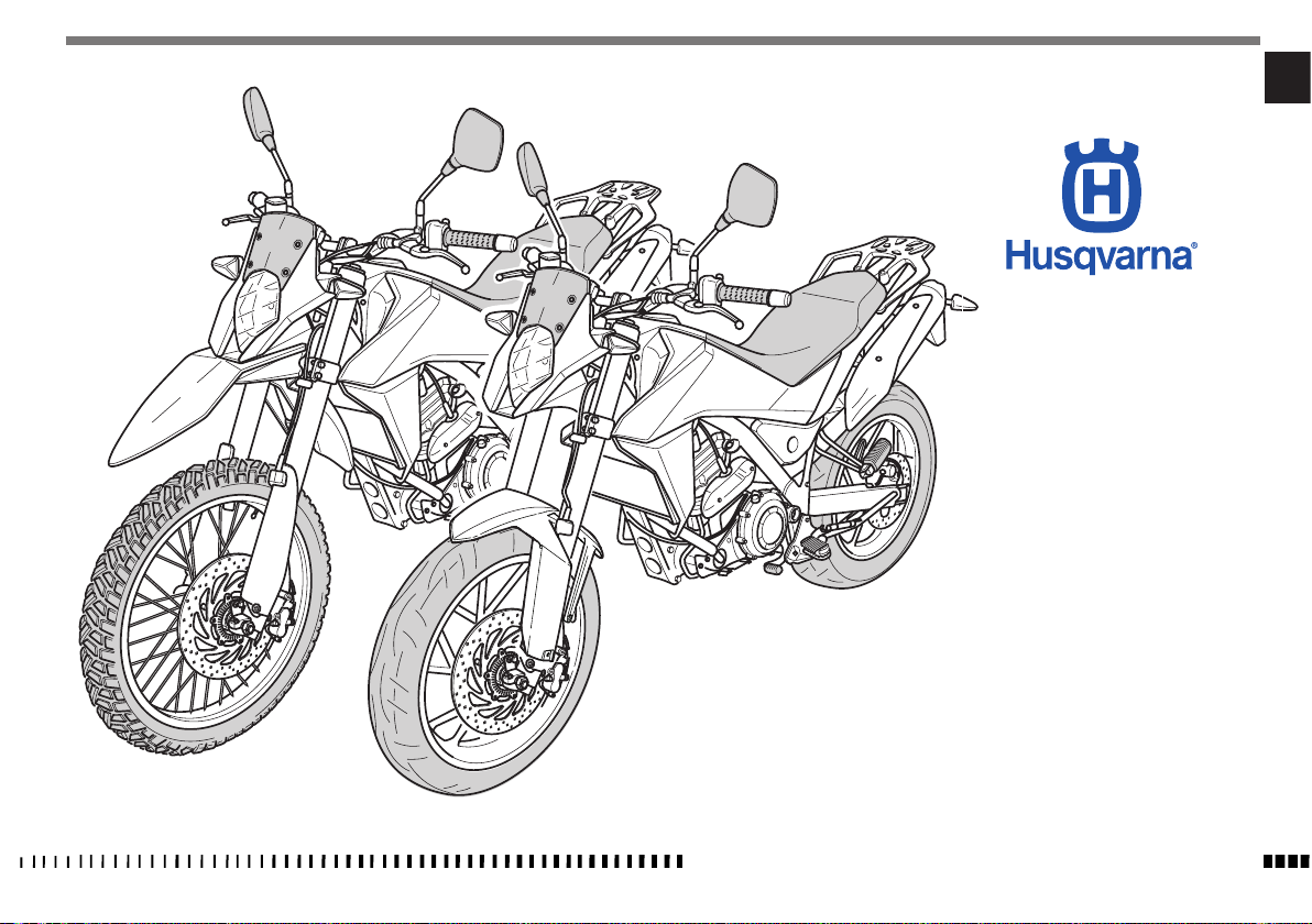
TR 650 TERRA MY14
TR 650 STRADA MY14
IT
Ed. 05-2013 - Rev. 00
Dove non diversamente specificato, i dati e le prescrizioni si riferiscono a tutti i modelli.
CARATTERISTICHE - USO - MANUTENZIONE
IT - 1
Page 4

SOMMARIO Pag.
PRESENTAZIONE .......................................................... 3
AVVERTENZE IMPORTANTI.............................................3
DEFINIZIONE DI IMPIEGO ............................................. 4
AVVERTENZE GENERALI ................................................4
DATI PER L’IDENTIFICAZIONE ........................................7
DATI TECNICI ...............................................................8
TABELLA DI LUBRIFICAZIONE, RIFORNIMENTI ................9
VISTA GENERALE MOTO .............................................. 10
COMANDI .................................................................. 12
STRUMENTO COMBINATO ........................................... 13
ISTRUZIONI PER L’USO DEL MOTOCICLO
........................... 20
FUSIBILI .................................................................... 42
APPENDICE ................................................................ 43
OPERAZIONI DI PRECONSEGNA ...................................45
INDICE ALFABETICO ....................................................46
MANUTENZIONE PERIODICA ...................... APPENDICE A
lLe indicazioni di destra e sinistra si riferiscono ai due
Note
lati del motociclo rispetto al senso di marcia.
lZ: n° denti
l A: Austria
AUS: Australia
B: Belgio
BR: Brasile
CDN: Canada
CH: Svizzera
D: Germania
E: Spagna
F: Francia
FIN: Finlandia
GB: Gran Bretagna
I: Italia
J: Giappone
USA: Stati Uniti d’America
lDove non diversamente specificato, i dati e le prescri-
zioni si riferiscono a tutte le Nazioni.
IT - 2
CARATTERISTICHE - USO - MANUTENZIONE
Page 5
PRESENTAZIONE
Benvenuti nella famiglia motociclistica Husqvarna!
La Vostra nuova motocicletta Husqvarna é stata pro-
gettata e costruita per essere la migliore della sua
categoria. Le istruzioni di questo manuale sono state
preparate per fornire una guida semplice e chiara alla
manutenzione del motociclo. Per ottenere da esso le
migliori prestazioni, si raccomanda di seguire attentamente quanto riportato su questo manuale. In esso sono
racchiuse le istruzioni per effettuare le necessarie operazioni di manutenzione. Le riparazioni o le manutenzioni
più specifiche o di maggiore entità richiedono il lavoro
di meccanici esperti e l’uso di apposite attrezzature. Il
Vostro Concessionario Husqvarna ha i ricambi originali,
l’esperienza e tutte le attrezzature necessarie per renderVi un ottimo servizio.
Ricordare infine che il “Manuale di uso
e manutenzione” deve considerarsi
parte integrante del motociclo e come
tale rimanere allegato allo stesso anche in caso di rivendita.
Questo motociclo utilizza componenti progettati e re-
alizzati grazie a sistemi e tecnologie d’avanguardia e
sperimentati nelle competizioni.
Nelle motociclette da competizione ogni particolare é
verificato dopo ogni gara al fine di garantire sempre le
migliori prestazioni.
Per il corretto funzionamento del motociclo é necessario
attenersi alla tabella di controllo e manutenzione riportata nell’appendice A.
AVVERTENZE IMPORTANTI
1) I modelli TR650 STRADA e TR 650 TERRA
sono motocicli per impiego STRADALE garantiti esenti da
difetti e coperti da garanzia legale, a condizione che VENGA MANTENUTA LA CONFIGURAZIONE DI SERIE e rispettata
la tabella di manutenzione riportata nell’appendice A.
2) I motocicli partecipanti a competizioni di qualunque genere sono esclusi da
ogni garanzia, in tutte le loro parti.
IT
CARATTERISTICHE - USO - MANUTENZIONE
IT - 3
Page 6

IMPORTANTE
Per mantenere la “Garanzia di Funzionamento” del veicolo, il Cliente deve
seguire il programma di manutenzione
indicato sul libretto di uso e manutenzione eseguendo i tagliandi presso le
officine autorizzate HUSQVARNA.
Il costo per la sostituzione dei pezzi e
per la manodopera necessaria per rispettare il piano di manutenzione è a
carico del Cliente.
NOTA: la garanzia DECADE in caso di noleggio del motociclo.
ATTENZIONE*:
Ricordare SEMPRE che i motocicli partecipanti a competizioni di qualunque genere sono esclusi da OGNI GARANZIA, in
tutte le loro parti e che modiche alla
congurazione di serie comportano la
NON CONFORMITÀ DEL VEICOLO AL TIPO
OMOLOGATO rendendolo non idoneo alla
circolazione su strade pubbliche e quindi utilizzabile solo in “CIRCUITI CHIUSI”
da parte di soggetto in possesso delle
necessarie autorizzazioni/ abilitazioni
di guida.
Premessa importante
Leggere attentamente il presente manuale prestando
particolare attenzione alle note precedute dalle seguenti
avvertenze:
IT - 4
CARATTERISTICHE - USO - MANUTENZIONE
ATTENZIONE*:
Indica la possibilità di subire gravi lesioni personali fino al rischio di decesso
in caso di inosservanza delle istruzioni.
AVVERTENZA*:
Indica la possibilità di subire lesioni
personali o provocare danni al veicolo
in caso di inosservanza delle istruzioni.
Nota*:
Fornisce ulteriori utili informazioni.
Sostituzione dei particolari
In caso di sostituzione dei particolari, usare unicamente
particolari ORIGINALI Husqvarna.
ATTENZIONE*: Dopo una caduta ispezionare attentamente il motociclo. Assicurarsi che il comando del gas, i freni, la
frizione e tutti gli altri principali comandi e componenti non siano stati danneggiati. Guidare un motociclo danneggiato
può provocare gravi incidenti.
ATTENZIONE*: Non avviare o operare
sul motociclo senza aver indossato un
adeguato abbigliamento protettivo. Indossare sempre casco, stivali, guanti,
occhiali protettivi ed altro abbigliamento appropriato.
PRECAUZIONI PER I BAMBINI
ATTENZIONE*:
l Parcheggiare il veicolo dove non pos-
sa essere facilmente urtato o danneggiato.
Urti anche involontari possono pro-
vocare la caduta del veicolo con conseguente pericolo per le persone, in
modo particolare per i bambini.
l Per evitare cadute accidentali del vei-
colo, non parcheggiarlo mai su terre-
no molle o irregolare né sull’asfalto
reso rovente dal sole.
lPoiché il motore e l’impianto di sca-
rico possono divenire molto caldi,
parcheggiare la motocicletta in luoghi
dove i pedoni o i bambini non possano facilmente toccarli.
l Non lasciare il veicolo incustodito con
il motore acceso o la chiave inserita
nel commutatore di accensione.
DEFINIZIONE DI IMPIEGO
Questa moto è stata costruita in modo da resistere alle
normali sollecitazioni dell’impiego stradale.
AVVERTENZE GENERALI
Leggere attentamente le presenti avvertenze generali
prima di utilizzare il veicolo.
Borse e bauletti
ATTENZIONE*:
Il sovraccarico ed il carico non uniforme possono pregiudicare la stabilità di
marcia della moto.
Non superare il peso totale ammesso e
prestare attenzione alle avvertenze sul
carico.
- Adattare la regolazione del precarico molle, dell'ammortizzatore e della pressione di gonfiaggio degli
Page 7
pneumatici al peso totale.
- Verificare che il peso sia ripartito uniformemente a
sinistra e a destra.
- Gli oggetti più pesanti devono essere sistemati in
basso e all'interno.
- Prestare attenzione al carico massimo e alla velocità
massima, riportati sulla targhetta di avvertenza delle borse.
- Prestare attenzione al carico massimo e alla velocità
massima, riportati sulla targhetta di avvertenza del
bauletto.
Immobilizzatore elettronico
L'elettronica della moto rileva, tramite un'antenna ad
anello posizionata nell'interruttore di accensione, i
dati registrati nella chiave del veicolo. Solo se la chiave viene riconosciuta, la centralina consente di avviare
il motore.
- Custodire la chiave di riserva sempre separatamente
dalla chiave di accensione.
- Chiavi di riserva e chiavi di accensione sono reperibili solo presso i concessionari HUSQVARNA. Il
concessionario sarà tenuto a verificare la legittimità
dell'acquisto, poiché le chiavi fanno parte di un si-
stema di sicurezza.
Monossido di carbonio
Far funzionare il motore esclusivamente in un luogo aperto
o in un locale ben ventilato. Se si opera in spazi chiusi utilizzare un'adeguato sistema di aspirazione fumi.
ATTENZIONE*:
I fumi di scarico contengono monossido
di carbonio che, se inalato, può provocare la perdita di conoscenza e anche la
morte.
Parti del veicolo che si riscaldano
Prima di operare sul motore e sul gruppo di scarico
attendere che si raffreddino; questi componenti, durante il funzionamento del veicolo si riscaldano molto
e rimangono caldi per un certo periodo dopo lo spegnimento del motore.
AVVERTENZA*:
Pericolo di scottature, operare con cautela se necessario utilizzare adeguati
mezzi di protezione individuale.
Combustibile
ATTENZIONE*:
Il carburante utilizzato per la propulsione dei motori a scoppio è altamente infiammabile ed esplosivo.
Effettuare il rifornimento con il motore spento e in zone ventilate; non
fumare, evitare il contatto tra il carburante e fiamme libere, scintille ecc.
potrebbero causarne l'esplosione.
Non disperdere il carburante nell'ambiente.
Tenere lontano dalla portata dei bambini.
AVVERTENZA*:
Non inclinare eccessivamente il veicolo potrebbe verificarsi una fuoriuscita
di carburante.
CARATTERISTICHE - USO - MANUTENZIONE
Liquido refrigerante
Il liquido refrigerante in alcuni casi può diventare infiammabile, bruciando produce una fiamma invisibile
che tuttavia causa ustioni.
ATTENZIONE*:
Non versare liquido refrigerante sulle
parti calde come motore tubo di scarico
ecc.. potrebbe incendiarsi.
Durante le operazioni di manutenzione
utilizzare guanti in lattice.
Non lasciare mai il liquido refrigerante
in contenitori aperti e in posizioni accessibili sia per bambini che animali in
quanto è tossico.
Con motore caldo NON rimuovere il tappo del radiatore; il liquido è sotto pressione e potrebbe causare bruciature.
Olio motore
AVVERTENZA*:
Non disperdere l'olio nell'ambiente è
altamente inquinante.
Tenere lontano dalla portata dei bambini.
Utilizzare guanti in lattice, il contatto
prolungato con la pelle può causare seri
danni.
Conferire l'olio usato in appositi centri
di recupero autorizzati come previsto
dalle norme in vigore nel paese di utilizzo del veicolo.
IT - 5
IT
Page 8

Liquido freni
ATTENZIONE*:
Il liquido freni è altamente corrosivo e
quindi può danneggiare le superfici verniciate del veicolo e le parti in gomma.
Durante la manutenzione proteggersi
gli occhi con appositi occhiali e utilizzare
guanti di protezione.
In caso di contatto accidentale con gli
occhi risciacquare abbondantemente con
acqua corrente pulita e contattare immediatamente un medico.
Tenere lontano dalla portata dei bambini.
Batteria
ATTENZIONE*:
Effettuare le operazioni di ricarica della
batteria in locali ben areati in quanto
durante la ricarica la batteria produce
gas tossici e altamente infiammabili;
non fumare, usare fiamme libere o scintille.
Il liquido presente nella batteria è altamente corrosivo in caso di contatto
con la pelle lavarsi abbondantemente
con acqua corrente, è molto importante
proteggersi gli occhi perché anche una
piccola quantità di liquido potrebbe causare danni irreversibili agli occhi.
In caso di contatto con gli occhi lavarsi
abbondantemente con acqua corrente
fresca e pulita, nel caso il liquido venga
ingerito accidentalmente bere abbondanti quantità di acqua o latte.
In tutti i casi di contatto rivolgersi immediatamente ad un medico.
Il liquido della batteria è corrosivo non
versare sulle parti verniciate o in gomma.
Il liquido della batteria è altamente inquinante NON disperderlo nell'ambiente; alla fine della vita della batteria conferirla presso appositi centri di recupero
autorizzati come previsto dalle norme
in vigore nel paese di utilizzo del veicolo.
Tenere lontano dalla portata dei bambini.
IT - 6
CARATTERISTICHE - USO - MANUTENZIONE
Page 9
DATI PER L’IDENTIFICAZIONE
Il numero di identificazione del motore è stampigliato
sulla parte inferiore destra del carter motore, mentre
il numero di matricola del motociclo è stampigliato sul
cannotto di sterzo del telaio.
Riferite sempre, annotandolo anche sul presente libretto,
il numero stampigliato sul telaio quando
ordinate i ricambi o chiedete informazioni sul vostro
motociclo.
NUMERO TELAIO
TERRA USA
ZKH0H12A#EV000001
STRADA USA
ZKH0H12B#EV000001
(l) (▲)
IT
1
(♦)
NUMERO DI IDENTIFICAZIONE DEL MOTOCICLO
Il numero di serie composto da 17 caratteri si trova sul lato
destro del cannotto di sterzo.
(l) = Tipo modello
(▲) = Anno modello (2014)
(♦) = N° progressivo
(l) (▲)
(♦)
2
1. Matricola telaio
2. Matricola motore
CARATTERISTICHE - USO - MANUTENZIONE
IT - 7
Page 10

DATI TECNICI
MOTORE
Monocilindrico a 4 tempi e quattro valvole
Raffreddamento ......... a liquido ed elettroventola
Alesaggio ............................mm 100
Corsa ................................mm 83
Cilindrata ............................ cm3 652
Rapporto di compressione .................12,3:1
Avviamento .......................... elettrico
Tipo di combustibile ....benzina verde senza piombo
95ROZ/RON
DISTRIBUZIONE
Doppio albero a camme in testa; comandato da catena;
4 valvole
Gioco valvole (a motore freddo)
Aspirazione .....................0,23 ÷ 0,28 mm
Scarico ........................0,38 ÷ 0,43 mm
LUBRIFICAZIONE
A carter secco con serbatoio integrato nel telaio, filtro
olio a cartuccia.
ACCENSIONE
Elettronica con anticipo variabile a controllo digitale
Tipo candela .................“NGK” MAR9A-J-G06
Distanza elettrodi candela ....... 0,6 mm (± 0,1 mm)
ALIMENTAZIONE
Ad iniezione elettronica
TRASMISSIONE PRIMARIA
Ingranaggio conduttore su albero motore .......Z 37
Ingranaggio condotto su campana frizione ......Z 72
Rapporto di trasmissione ..................1,946
FRIZIONE
Multidisco in bagno d’olio con comando meccanico
CAMBIO VELOCITÁ
A innesti frontali sempre in presa
Rapporti di trasmissione
1a velocità ......................2,750 (33/12)
2a velocità ......................1,750 (28/16)
3a velocità ......................1,313 (21/16)
4a velocità ......................1,045 (23/22)
5a velocità ......................0,875 (21/24)
TRASMISSIONE SECONDARIA
Pignone uscita cambio .....................Z 16
Corona sulla ruota. . . . . . . . . . . . . . . . . . . . . . . . . Z 47
Rapporto di trasmissione ...................2,938
Dimensioni catena di trasmissione . 520KR0 112 maglie
RAPPORTI TOTALI DI TRASMISSIONE
in 1a velocità ..........................15,722
in 2a velocità ..........................10,005
in 3a velocità ...........................7,506
in 4a velocità ...........................5,974
in 5a velocità ...........................2,898
TELAIO
Monotrave, in tubi a sezione circolare, rettangolare, ellissoidale, in acciaio; telaietto posteriore in acciaio
SOSPENSIONE ANTERIORE
Tipo forcella teleidraulica a steli rovesciati
...........................steli ø 46 mm
Escursione ruota .......................190 mm
SOSPENSIONE POSTERIORE
Monoammortizzatore idraulico (regolazione del precarico molla e freno idraulico di estensione)
Escursione ruota .......................190 mm
FRENO ANTERIORE
A disco fisso Ø 300 mm con comando idraulico e pinza
flottante
FRENO POSTERIORE
A disco flottante Ø240 mm con comando idraulico e pinza flottante
RUOTE
TR 650 STRADA
Anteriore ................in lega leggera: 2,5”x19”
Posteriore ...............in lega leggera: 3”x17”
TR 650 TERRA
Anteriore ..a raggi con cerchio in alluminio: 1,85”x21”
Posteriore
. . . . .a raggi con cerchio in alluminio: 3”x18” (no ABS)
. . . . . . .a raggi con cerchio in alluminio: 3”x17” ( ABS)
IT - 8
CARATTERISTICHE - USO - MANUTENZIONE
Page 11

PNEUMATICI
TR 650 STRADA
Anteriore .................110/80 R19” M/C 59 V
Posteriore ................140/80 R17” M/C 59 V
Pressione di gonfiaggio a freddo (solo pilota)
Anteriore ..................2,2 kg/cm2 (31.29 psi)
Posteriore .................2,0 kg/cm2 (28.45 psi)
Pressione di gonfiaggio a freddo (pilota e passeggero)
Anteriore ..................2,2 kg/cm2 (31.29 psi)
Posteriore .................2,5 kg/cm2 (35.56 psi)
TR 650 TERRA
Anteriore ............90/90 21” M/C 54 H TL (ABS)
90/90 21” M/C 54 S (no ABS)
Posteriore ............140/80 17” M/C 59 H (ABS)
140/80 18” M/C 70 S (no ABS)
Pressione di gonfiaggio a freddo (solo pilota)
Anteriore ..................2,0 kg/cm2 (28.45 psi)
Posteriore .................2,5 kg/cm2 (35.56 psi)
Pressione di gonfiaggio a freddo (pilota e passeggero)
Anteriore ..................2,0 kg/cm2 (28.45 psi)
Posteriore .................2,8 kg/cm2 (39.82 psi)
DIMENSIONI, PESO, CAPACITÀ
Interasse ...........................mm 1500
Lunghezza totale (STRADA) .............mm 2248
Lunghezza totale (TERRA) ...............mm 2267
Larghezza massima ....................mm 885
Altezza massima (STRADA) ..............mm 1205
Altezza massima (TERRA) ...............mm 1223
Altezza sella (STRADA) ..................mm 860
Altezza sella (TERRA) ........mm 875 (no ABS - 18”)
mm 865 (ABS - 17”)
Altezza minima da terra (STRADA) .........mm 250
Altezza minima da terra (TERRA) mm 266 (no ABS 18”)
mm 257 (ABS 17”)
Peso, senza carburante (STRADA). ...........kg 177
Peso, senza carburante. (TERRA) ............kg 174
Capacità serbatoio carburante compresa la riserva
Riserva carburante ....................circa l 2,5
Capacità circuito di raffreddamento ..........l 1,160
Sostituzione olio e filtro ....................l 2,0
Rabbocco olio tra livello minimo e livello massimo
TABELLA DI LUBRIFICAZIONE, RIFORNIMENTI
Olio lubrificazione motore, cambio, trasmissione primaria
..............CASTROL POWER1 RACING SAE 10W-50
Liquido refrigerante motore
Liquido impianti frenanti ..
..CASTROL MOTORCYCLE COOLANT
CASTROL RESPONSE SUPER DOT 4
Lubrificazione a grasso .........CASTROL LM GREASE 2
Lubrificazione catena trasmissione secondaria
...............CASTROL CHAIN LUBE RACING
Protettivo contatti elettrici
............. CASTROL METAL PARTS CLEANER
IT
...l 14
. l 0,25
CARATTERISTICHE - USO - MANUTENZIONE
IT - 9
Page 12
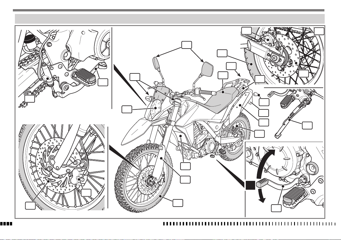
VISTA GENERALE MOTO
17
19
7
13
8
11
18
16
14
12
21
10
15
22
9
6
20
5
23
4
4
3
2
N
3
1
IT - 10
2
CARATTERISTICHE - USO - MANUTENZIONE
1
5
Page 13
LEGENDA
1. Ruota anteriore
2. Disco freno anteriore
3. Pinza freno anteriore
4. Forcella anteriore
5. Pedale comando cambio (si innesta la prima mar-
cia spingendo in basso la leva; per tutte le altre
marce spingerla in alto. La posizione di “folle” si
trova tra la prima e la seconda marcia)
6. Cavalletto laterale
7. Corona
8. Ruota posteriore
9. Portatarga
10. Indicatori di direzione posteriori
11. Fanale posteriore
12. Sella
13. Specchietti retrovisori
14. Indicatori di direzione anteriori
15. Fanale anteriore
16. Pedale comando freno posteriore
17. Pompa freno posteriore
18. Disco freno posteriore
19. Pinza freno posteriore
20. Pedane passeggero
21. Maniglie passeggero
22. Silenziatori di scarico
23. Radiatore
24. Tappo serbatoio carburante
25. Strumento digitale
26. Interruttore di accensione
27. Commutatore destro
28. Pulsante ENGINE STOP (arresto di emergenza del .
motore)
29. Pulsante avviamento motore
30. Leva comando freno anteriore
31. Manopola comando gas
32. Leva comando frizione
33. Commutatore sinistro
34. Commutatore ABS (ove previsto)
26
25
27
IT
30
28
29
31
32
24
34
33
CARATTERISTICHE - USO - MANUTENZIONE
IT - 11
Page 14
COMANDI
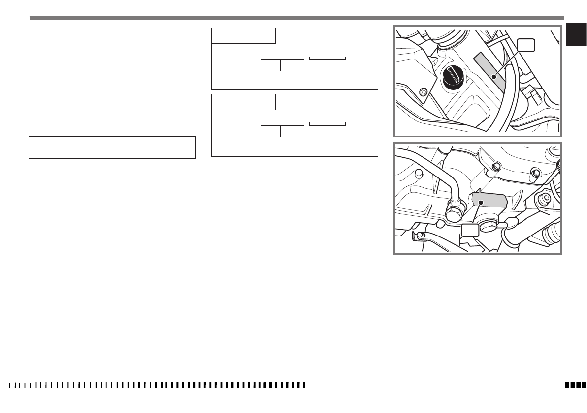
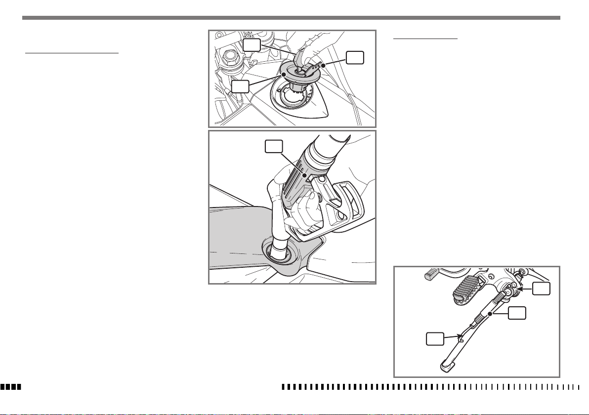
RIFORNIMENTO DI CARBURANTE
Utilizzare esclusivamente benzina SENZA PIOMBO a 95
ottani o superiore.
AVVERTENZA*:
L'utilizzo di benzina con piombo causa
danni irreversibili al catalizzatore che
perde la sua efficacia.
ATTENZIONE*:
La benzina è estremamente infiammabile e può diventare esplosiva in particolari condizioni. Spegnere sempre il
motore, non fumare o avvicinare fiam-
me o scintille nell’area dove si effettua
il rifornimento o si conserva il carburante.
ATTENZIONE*:
Non riempire il serbatoio oltre il limite
inferiore del bocchettone di carico. Dopo
il rifornimento, accertarsi della corretta
chiusura del tappo (3) del serbatoio.
- Sollevare la linguetta (1), introdurre la chiave (2),
ruotarla in senso antiorario e rimuovere il tappo serbatoio (3).
- Introdurre completamente l'erogatore (4) della
pompa benzina nel serbatoio prima di effettuare il
rifornimento (vedi figura).
- Effettuato il rifornimento rimontare il tappo (3)
agendo in senso inverso allo smontaggio.
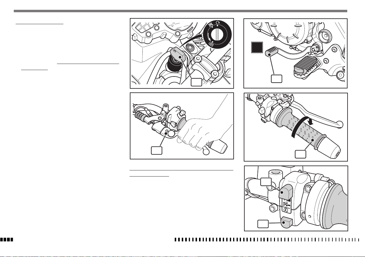
CAVALLETTO LATERALE
2
1
3
4
Ogni motociclo è fornito di un cavalletto laterale (1).
Per abbassarlo agire con il piede sull’appiglio (2).
ATTENZIONE*:
Il cavalletto è progettato per supportare il SOLO PESO DEL MOTOCICLO. Non sedersi sul veicolo utilizzando il cavalletto
come supporto; potrebbero verificarsi
delle rotture con conseguenti gravi lesioni personali.
ATTENZIONE*:
Il cavalletto non è dotato di ritorno automatico.
Il cavalletto è dotato di un'interruttore
rotativo che spegne il motore nel caso si
inserisca una marcia con il cavalletto in
posizione abbassata.
Controllare periodicamente il cavalletto laterale (vedi
“Scheda di manutenzione periodica”); verificare che le
molle non siano danneggiate e che il cavalletto si muova
liberamente. Nel caso il cavalletto fosse rumoroso, lubri-
ficare e controllare il perno (A) di fissaggio.
A
1
2
IT - 12
CARATTERISTICHE - USO - MANUTENZIONE
Page 15
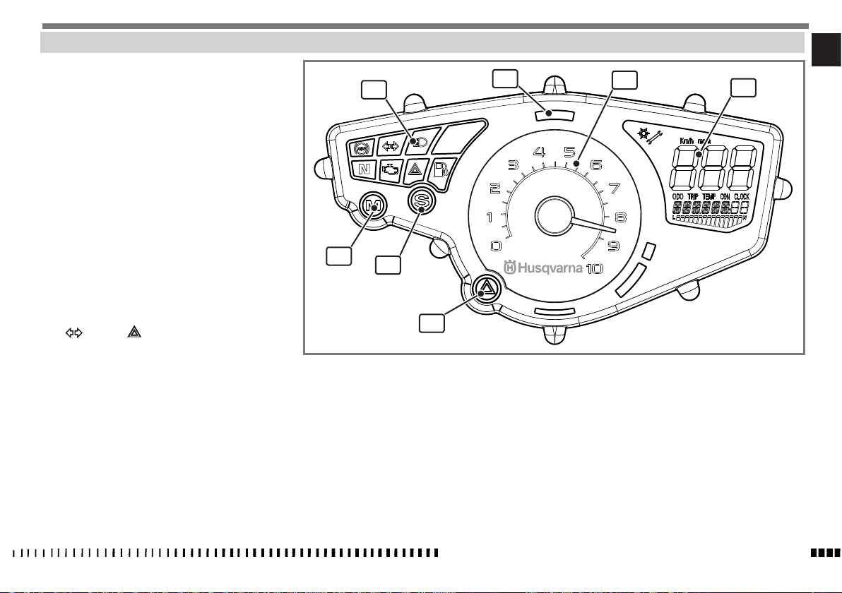
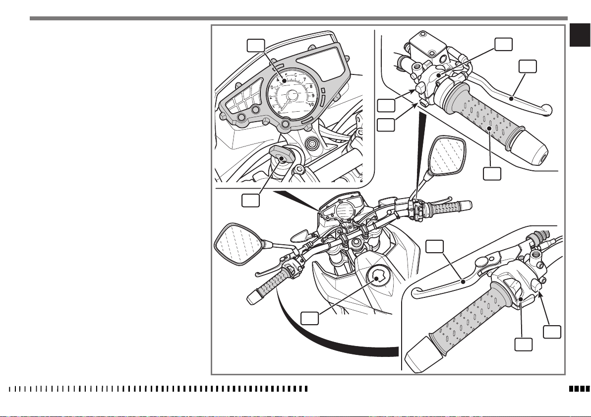
STRUMENTO COMBINATO
IT
Il motociclo è equipaggiato con uno strumento combinato
suddiviso nelle seguenti zone:
1. Spie di segnalazione (vedi “ Descrizione spie di
segnalazione”).
2. Display multifunzione (vedi “ Descrizione di-
splay multifunzione”).
3. Contagiri
Indica il numero di giri del motore.
4. Spia sistema antifurto (optional)
(colore ROSSO).
5. Tasto “MODE”
6. Tasto “SET”
Permette di visualizzare le varie funzioni del
display multifunzione vedi “ Descrizione display
multifunzione”.
7. Tasto “LAMPEGGIO EMERGENZA (HAZARD)”
Premuto si illuminano lampeggiando contempo-
raneamente gli indicatori di direzione, la spia
e la spia .
Ripremere per disattivare il lampeggio di emer-
genza.
1
5
6
7
4
3
2
CARATTERISTICHE - USO - MANUTENZIONE
IT - 13
Page 16
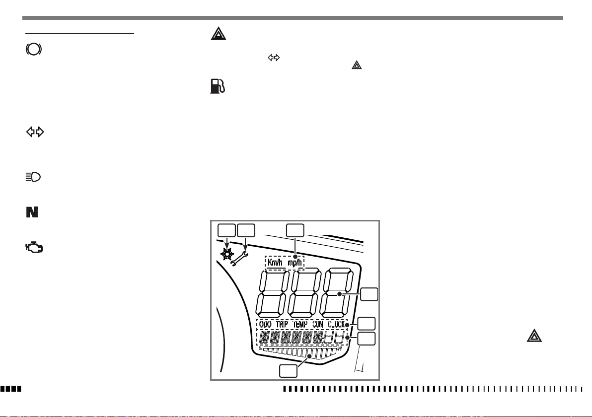
DESCRIZIONE SPIE DI SEGNALAZIONE
ABS
Spia "ABS"
Portando la chiave in posizione "ON" la spia
lampeggia, e continua a lampeggiare, fino a
che il veicolo inizia a muoversi in avanti. Se il
sistema funziona correttamente la spia si spe-
gne; se l'autodiagnosi del sistema verifica una
anomalia, o se il sistema viene disattivato, la
spia rimane accesa.
Spia indicatori di direzione (colore VERDE)
Si illumina lampeggiando quando sono inseriti
gi indicatori di direzione o è stato premuto il
tasto “HAZARD”.
Spia abbagliante (colore BLU)
Si illumina fissa quando si inserisce la luce ab-
bagliante.
Spia folle (colore VERDE)
Si illumina fissa quando è inserita la marcia
folle.
Spia Engine Diagnosi (colore ARANCIO)
Si illumina fissa quando la centralina del moto-
re ha diagnosticato una anomalia di funzionamento.
Esistono due stati di anomalia:
- Anomalia grave: il motore si spegne ed è
necessario rivolgersi ad un concessionario
HUSQVARNA.
- Anomalia con funzionamento di emer-
genza: il motore funziona con prestazioni
ridotte in modo da potersi recare presso il
più vicino concessionario HUSQVARNA per il
controllo dell’anomalia.
Spia “HAZARD” (colore ROSSO)
Si illumina lampeggiando in contemporanea
con la spia e con gli indicatori di direzione
quando è stato premuto l’interruttore .
Spia riserva carburante (colore ARANCIO)
Si illumina quando il livello del carburante ha
raggiunto un livello tale, per cui nel serbatoio
sono rimasti circa 3 litri di carburante.
E’ necessario effettuare il rifornimento.
Nota *:
La spia riserva carburante normalmente si spegne
qualche tempo dopo aver effettuato il rifornimen-
to.
1 2 3
4
5
6
7
DESCRIZIONE DISPLAY MULTIFUNZIONE
1. Indicatore “ICE”:
Appare quando la temperatura esterna è inferio-
re a 3°C o 37,4°F
2. Indicatore “SERVICE”:
Appare indicando il raggiungimento dell’inter-
vallo di manutenzione.
Rivolgersi al concessionario HUSQVARNA per le
operazioni di manutenzione periodica.
3. Indicazione scala contachilometri km/h o mp/h
(vedi “impostazione unità di misura”)
4. Indicatore di velocità
5. Parametri di visualizzazione:
In questo campo si possono impostare singolar-
mente i seguenti parametri che verranno visua-
lizzati nel campo 6.
ODO = Contachilometri / Contamiglia totale
TRIP = Contachilometri / Contamiglia parziale
(per impostare la funzione vedi “Impostazione
parametri”)
TEMP = Temperatura aria (AIR BOX) / Tempera-
tura liquido di raffreddamento
CON = Consumo effettivo di carburante / Consu-
mo medio.
CLOCK = Orologio ( Vedi “Regolazione orolo-
gio”).
6. Visualizza il valore del parametro impostato nel
campo (5).
7. Si illumina in sequenza da sinistra verso destra
con l’aumento della temperatura del liquido di
raffreddamento.
In caso di sovratemperatura, la spia si illu-
mina fissa e la barra (7) lampeggia.
IT - 14
CARATTERISTICHE - USO - MANUTENZIONE
Page 17
> 4”
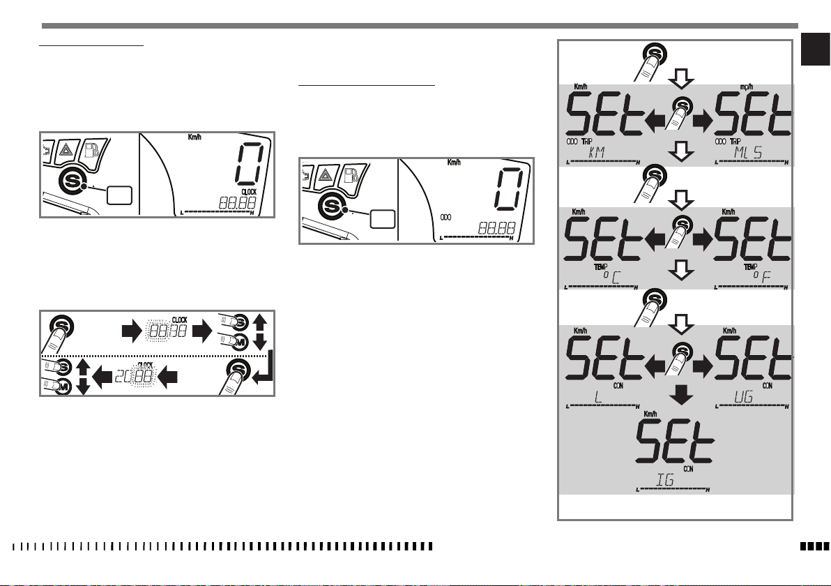
REGOLAZIONE OROLOGIO
L’impostazione dell’orologio deve essere effettuata con
moto ferma e chiave in posizione ON.
L’impostazione dell’orologio è 24 ore.
- Premere il tasto “S” (1) fino a visualizzare la scritta
“CLOCK” sul display.
oppure dopo 10 secondi l’impostazione viene memoriz-
zata automaticamente.
IMPOSTAZIONE UNITÀ DI MISURA
L’impostazione delle unità di misura deve essere effettuata con moto ferma e chiave in posizione ON.
- Premere il tasto “S” (1) fino a visualizzare la scritta
“ODO” o “TEMP” sul display.
> 4”
IT
1
- Premere il tasto “S” per più di 4 secondi, sul display
lampeggiano le ore.
- Il valore delle ore aumenta di una unità ad ogni pressione breve del tasto “S”.
- Il valore delle ore diminuisce di una unità ad ogni pressione breve del tasto “M”.
4”<
- Premere il tasto “S” per più di 4 secondi, si memorizzano le ore impostate e sul display lampeggiano i
minuti.
- Il valore dei minuti aumenta di una unità ad ogni pressione breve del tasto “S”.
- Il valore dei minuti diminuisce di una unità ad ogni
pressione breve del tasto “M”.
- Alla fine dell’impostazione dell’ora per memorizzare
l’impostazione premere per più di 4 secondi il tasto “S”
1
- Premere il tasto “S” per più di 4 secondi, sul display si
visualizza la scritta “SET” e sul display appare l’unità
di misura attualmente in uso.
- Premere una volta il tasto “S” per variare l’unità di
misura, scelta l’unità di misura premere il tasto “S”
per più di 4 secondi per confermare il dato impostato e
passare all’impostazione della scala successiva.
Le unità di misura impostabili sono:
Km / mp = sul display apparirà:
- la velocità espressa in “km/h” o “mp/h” ;
- la quantità di strada totale percorsa in “km” o “mp”
- la quantità parziale di strada percorsa “TRIP” in “km”
o “mp”.
Temperatura = °C / °F
Quantità di carburante:
L = (litri) - UG = US/GAL - IG = IM/GAL
- Alla fine dell’ultima impostazione per uscire dalla fase
“SET” premere per più di 4 secondi il tasto “S” oppure
dopo 10 secondi il programma esce automaticamente.
CARATTERISTICHE - USO - MANUTENZIONE
> 4”
> 4”
IT - 15
Page 18
IMPOSTAZIONE PARAMETRI
Con cruscotto alimentato, premere il tasto “S” (1) per
visualizzare le varie funzioni del display:
ODO ; TRIP ; TEMP ; CON ; CLOCK
1
Le funzioni “ODO”, “TEMP”, e “CLOCK” sono solo di visualizzazione.
Funzione TRIP:
Con abilitata questa funzione, è possibile premendo il
tasto “S” per un tempo superiore a 4 secondi, azzerare
ed avviare un nuovo conteggio parziale dei chilometri /
miglia successivamente percorsi.
Con questa funzione impostata dopo l’illuminazione della lampada della riserva carburante e premendo il tasto
“S” (1) per un tempo superiore a 4 secondi è possibile
visualizzare il consumo del carburante (in litri o Galloni
a seconda dell’unità di misura scelta) dal momento che
si è entrati in riserva in poi.
Funzione CON:
Con abilitata questa funzione è possibile premendo il
tasto “S” per un tempo superiore a 4 secondi azzerare
e avviare un nuovo conteggio dei litri / Gall che si consumeranno dal momento dell’azzeramento e resettare il
consumo medio (L/100 Km).
IT - 16
1
CARATTERISTICHE - USO - MANUTENZIONE
Page 19
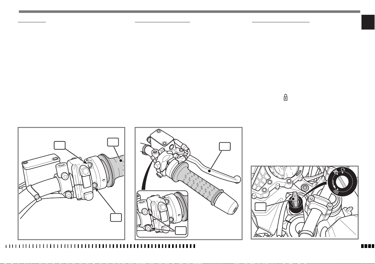
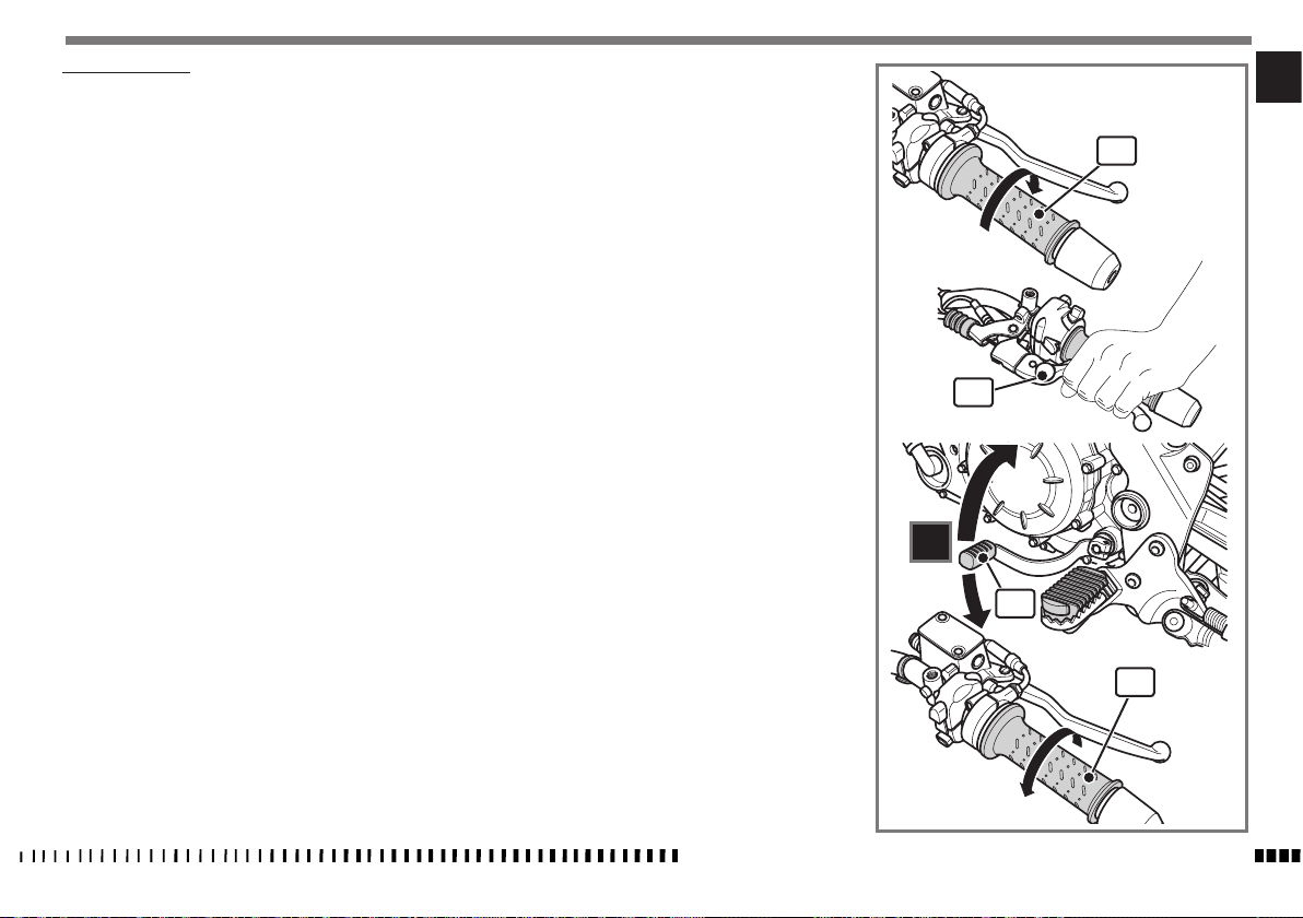
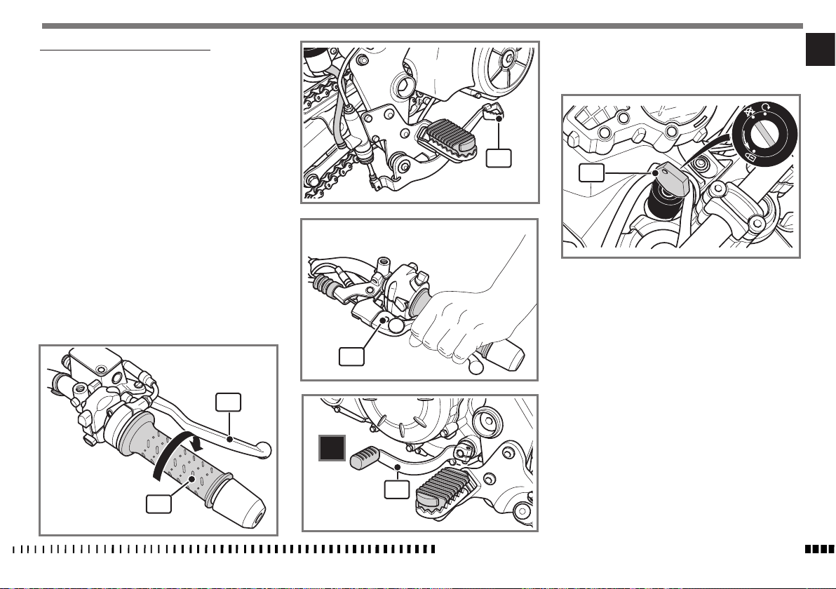
COMANDO GAS
La manopola (1) del gas è situata sul lato destro del
manubrio. La posizione del comando sul manubrio può
essere regolata allentando le due viti di fissaggio (2).
AVVERTENZA*:
Non dimenticare di stringere le viti (2)
dopo la regolazione.
COMANDO FRENO ANTERIORE
La leva (1) del freno è situata sul lato destro del manu-
brio. La posizione del comando sul manubrio può essere
regolata allentando le due viti di fissaggio (2).
ATTENZIONE*:
A regolazione avvenuta, ruotare il manubrio verso destra fino a finecorsa, e
controllare che la leva non tocchi la carrozzeria.
Un interruttore di stop, all'atto della frenata, provoca
l'accensione della lampada del fanale posteriore.
AVVERTENZA*:
Non dimenticare di stringere le viti (2)
dopo la regolazione.
INTERRUTTORE DI ACCENSIONE
L’interruttore di accensione consta di tre posizioni:
Posizione "OFF":
Posizione di estrazione chiave e spegnimento motore
Posizione "ON":
Dalla posizione OFF ruotare in senso orario la chiave (1)
in posizione ON; si avranno inseriti l’accensione, le luci di
posizione e gli utilizzatori e si potrà avviare il motociclo;
Posizione “ ”:
Posizione bloccasterzo (Vedi bloccasterzo)
IT
2
1
2
2
1
1
CARATTERISTICHE - USO - MANUTENZIONE
ON
OFF
PUSH
IT - 17
Page 20
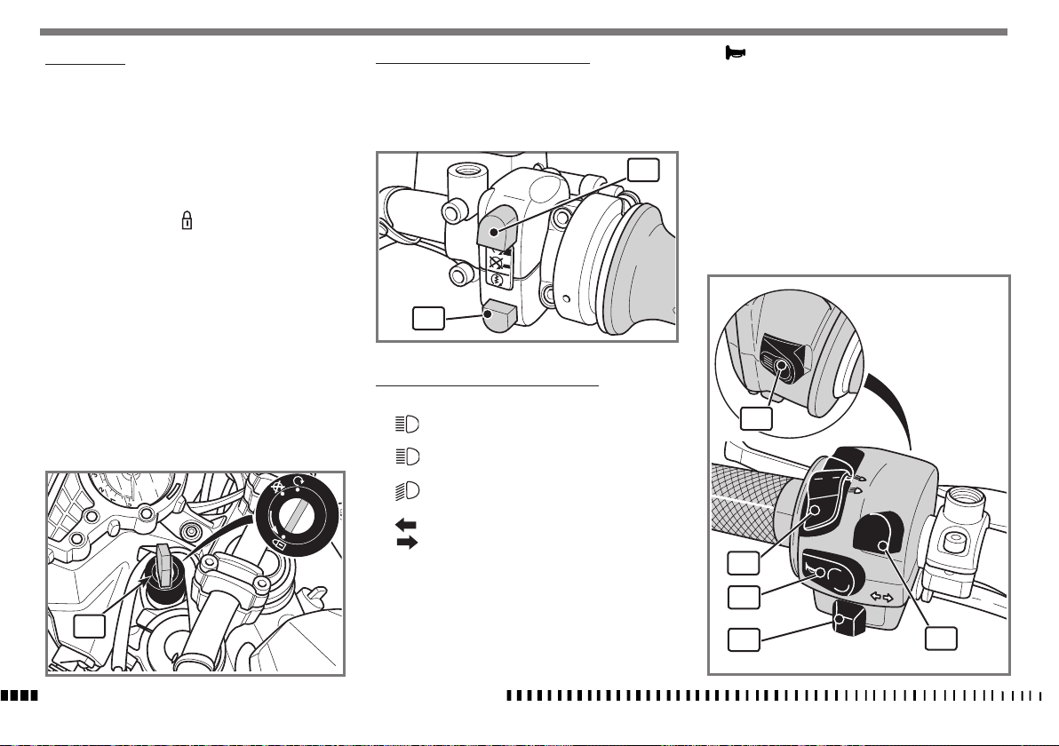
BLOCCASTERZO
Il motociclo è fornito di un bloccasterzo posto sul bloc-
chetto di avviamento.
Per bloccare lo sterzo, operare nel modo seguente:
COMMUTATORE DESTRO SUL MANUBRIO
Il commutatore destro ha i seguenti comandi:
1) Pulsante avviamento motore
2) Interruttore di EMERGENZA arresto motore.
5) Avvisatore acustico.
- Ruotare il manubrio verso sinistra fino a finecorsa.
- Introdurre la chiave nel blocchetto (1), premere
la chiave verso il basso e ruotarla dalla posizione
“OFF” alla posizione “ ” quindi estrarla.
- Per sbloccare lo sterzo agire inversamente al bloc-
caggio.
ON
OFF
PUSH
1
IT - 18
CARATTERISTICHE - USO - MANUTENZIONE
2
1
COMMUTATORE SINISTRO SUL MANUBRIO
Il commutatore sinistro ha i seguenti comandi:
1) Flash abbagliante (ritorno automatico).
2) Comando selezione luce abbagliante.
Comando selezione luce anabbagliante.
3) Attivazione indicatori di direzione sinistri.
Attivazione indicatori di direzione destri.
Per disattivare l’indicatore, premere sulla levetta di comando una volta che è ritornata al centro.
4) Commutatore ABS (ove previsto)
- Premendo il pulsante per più di 3 secondi si inserisce o si disinserisce il sistema di frenata assistita
“ABS”.
1
ABS
2
5
3
4
Page 21
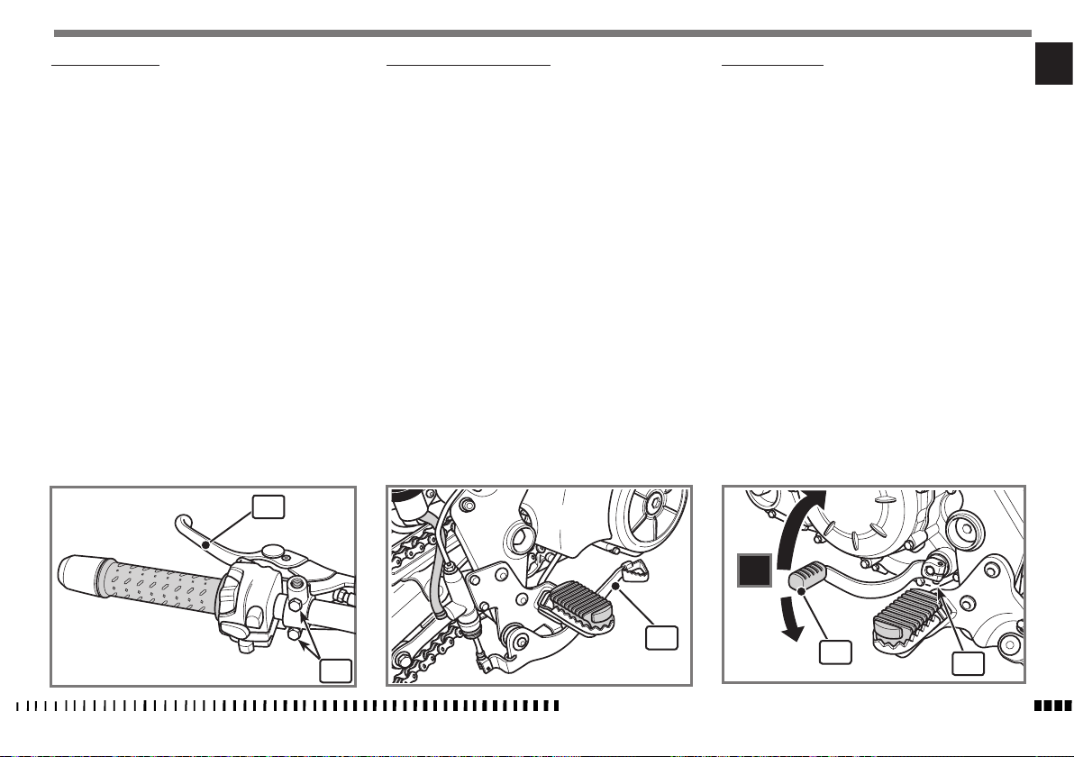
COMANDO FRIZIONE
La leva (1) di comando della frizione è situata sul lato
sinistro del manubrio.
La posizione del comando frizione sul manubrio può essere regolata allentando le viti (2) di fissaggio.
ATTENZIONE*:
A regolazione avvenuta, ruotare il manubrio verso sinistra fino a finecorsa,
e controllare che la leva non tocchi la
carrozzeria.
Sul comando frizione è presente un'interruttore di
"STOP" che consente l'avviamento della moto con marcia inserita e leva della frizione tirata (il cavalletto deve
essere in posizione sollevata)
AVVERTENZA*:
Non dimenticare di stringere le viti (2)
dopo la regolazione.
COMANDO FRENO POSTERIORE
Il pedale (1) di comando del freno posteriore si trova sul
lato destro del motociclo.
Un interruttore di stop, all’atto della frenata, provoca
l’accensione della lampada del fanale posteriore.
COMANDO CAMBIO
La leva (1) è posta sul lato sinistro del motore. Il pilota,
ad ogni cambio di velocità, deve lasciare libero il pedale
che tornerà nella sua posizione centrale; la posizione di
“folle” (N) si trova tra la prima e la seconda marcia.
Si innesta la prima marcia spingendo in basso la leva;
per tutte le altre marce spingerla in alto.
La posizione della leva (1) sull’albero può essere variata. Per effettuare questa operazione occorre allentare la
vite (2), togliere la leva e porla in una nuova posizione
sull’albero.
Bloccare la vite ad operazione effettuata.
ATTENZIONE*: Evitare di inclinare eccessivamente la leva verso il basso!
AVVERTENZA*: Non cambiare le marce
senza disinnestare la frizione e chiudere il gas. Il motore potrebbe andare
“fuorigiri” e subire danni.
ATTENZIONE*: Non rallentare scalando le
marce quando ci si trova ad una velocità
che potrebbe portare il motore “fuorigiri” oppure far perdere aderenza alla
ruota posteriore, se si selezionasse la
marcia immediatamente inferiore.
IT
1
1
2
CARATTERISTICHE - USO - MANUTENZIONE
5
4
3
2
N
1
1
2
IT - 19
Page 22

ISTRUZIONI PER L’USO DEL MOTOCICLO
NOTA*: Se non avete condenza col
funzionamento del motociclo, prima di
guidarlo, leggete attentamente le istruzioni contenute nel paragrafo “COMANDI”.
CONTROLLI PRELIMINARI
Ogniqualvolta si intende usare il motociclo si deve ef-
fettuare un controllo generale procedendo alle seguenti
veriche:
- controllare il livello del carburante e dell’olio motore;
- controllare il livello del fluido freni;
- controllare lo sterzo girando il manubrio a fondo corsa
in entrambi i sensi;
- controllare la pressione dei pneumatici e il loro stato di
usura;
- la tenuta di strada della moto può non essere ottimale già al raggiungimento della scolpitura minima del
battistrada prescritta per legge. Sostituire i pneumatici
quando si raggiunge la scolpitura minima.
- controllare la tensione della catena;
- controllare ed eventualmente registrare il comando
gas;
- ruotare la chiave dell’interruttore di accensione in posizione ON: verificare l’illuminazione del display dello
strumento;
- verificare l'accensione delle luci di posizione, anabbagliante, abbagliante e l'accensione della relativa spia;
- azionare gli indicatori di direzione, e verificare l’accen-
sione della spia;
- verificare l’accensione della luce dello stop posteriore.
Il rodaggio del motore è fondamentale per garantirne la
successiva durata ed il corretto funzionamento.
Percorrere, se possibile, strade con molte curve e/o col-
IT - 20
CARATTERISTICHE - USO - MANUTENZIONE
linose, dove il motore, le sospensioni ed i freni vengono
sottoposti ad un rodaggio più efcace.
Ricordare che anche i pneumatici nuovi hanno la neces-
sità di essere rodati per ottenere la massima aderenza;
guidare con cautela per i primi 100 km (62,5 mi).
Variare la velocità di guida durante il rodaggio.
In questo modo si consente di "caricare" il lavoro dei
componenti e successivamente "scaricare", raffreddando
le parti del motore.
Sebbene sia importante sollecitare i componenti del
motore durante il rodaggio, fare molta attenzione a non
eccedere.
Soltanto dopo i primi 1000 km (625 mi)
di rodaggio è possibile ottenere le migliori prestazioni in accelerazione del
veicolo.
Attenersi alle seguenti indicazioni:
non accelerare bruscamente e completamente quando il
motore sta funzionando ad un regime di giri basso, sia
durante che dopo il rodaggio.
Durante i primi 100 km (62 mi) agire con cautela sui
freni, ed evitare brusche e prolungate frenate.
Ciò per consentirne un corretto assestamento del materiale d'attrito delle pastiglie sui dischi freno.
Durante i primi 1000 km (625 mi) di percorrenza, non
superare mai 5000 giri/min (rpm) (vedi tabella).
Dopo i primi 1000 km (625 mi) di funzionamento, eseguire i controlli previsti
nella scheda di manutenzione periodi-
ca, al ne di evitare danni a sé stessi,
agli altri e/o al veicolo.
Dopo i 1000 km (625 mi) si possono pretendere dal motore maggiori prestazioni, senza tuttavia fare girare il
motore oltre il regime di giri massimo consentito.
Massimi numeri di giri del motore raccomandati:
percorrenza Km (mi) giri/min (rpm)
0-1000 (0-625) .....................................................5000
Page 23

INDIVIDUAZIONE DEGLI INCONVENIENTI DI FUNZIONAMENTO
Il seguente elenco di eventuali inconvenienti di funzionamento serve, in linea generale, per individuarne l’origine
ed attuarne il rimedio.
Rivolgersi comunque ad un concessionario ufciale Husqvarna che ha l'esperienza e le necessarie competenze
per fornirvi tutta l'assistenza di cui potreste avere biso-
gno.
Il motore non si avvia.
- Inadeguata tecnica d’avviamento: attenersi a quanto
riportato al paragrafo “Avviamento del motore”.
- Cavalletto abbassato: sollevare il cavalletto.
- Mancanza carburante: effettuare il rifornimento di carburante.
- Batteria scarica / difettosa: controllare/caricare la bat-
teria.
- Motorino d’avviamento difettoso: riparare o sostituire.
- Pulsante d’avviamento difettoso: sostituire il commuta-
tore.
Il motore stenta ad avviarsi.
- Candela sporca o in cattive condizioni: pulire o sostitui-
re.
- Batteria scarica: caricare.
Il motore si surriscalda.
- Ostruzioni al flusso d’aria sul radiatore: pulire.
- Ventola di raffreddamento non parte: controllare/sostituire il termointerruttore.
- Ventola difettosa: sostituire.
- Insufficiente quantità di liquido nel radiatore: rabboccare.
- Insufficiente quantità di olio: rabboccare.
Il motore é carente di potenza.
- Filtro aria sporco: pulire.
- Cambiare la candela.
- Gioco valvole non corretto: regolare.
- Compressione insufficiente: verificarne la causa.
- Corpo farfallato non regolato correttamente: regolare.
Il motore batte in testa.
- Forte deposito di carbonio sul cielo del pistone o nella
camera di scoppio: pulire.
- Candela difettosa o con grado termico errato: sostituire.
- Carburante non adeguato; utilizzare solo benzina senza piombo con 95 ottani o superiore.
L’alternatore non carica o carica insufficientemente.
- Cavi sul regolatore di tensione mal collegati o in corto
circuito: collegare correttamente o sostituire.
- Bobina alternatore difettosa: sostituire.
- Rotore smagnetizzato: sostituire.
- Regolatore di tensione difettoso: sostituire.
La batteria si surriscalda.
- Regolatore di tensione difettoso: sostituire.
Difficoltà ad innestare le marce.
- Frizione non regolata correttamente : regolare la frizione.
La frizione slitta.
- Carico molle insufficiente: sostituire.
- Dischi frizione consumati: sostituire.
I freni non funzionano adeguatamente.
- Pastiglie consumate: sostituire.
- Presenza aria nell'impianto: spurgare l'aria.
- Livello olio basso: ripristinare il livello.
IT
CARATTERISTICHE - USO - MANUTENZIONE
IT - 21
Page 24
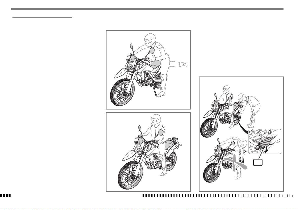
SALITA /DISCESA PILOTA E PASSEGGERO
Norme generali
Leggere attentamente le indicazioni riportate di segui-
to in quanto forniscono informazioni importanti al fine
della sicurezza del pilota e del passeggero e per evitare
danni a cose al motociclo.
La salita e la discesa dal motociclo deve essere effettuata
sempre dalla parte sinistra della moto, con le mani libere, senza impedimenti e con cavalletto abbassato.
Il pilota deve essere il primo a salire e l'ultimo a scendere
dal motoveicolo e deve governare la stabilità della moto
durante la salita e la discesa del passeggero.
Non scendere dal veicolo saltando o allungando la gamba, scendere sempre eseguendo le operazioni descritte
nel relativo paragrafo.
Salita del pilota
Con moto posizionata sul cavalletto laterale effettuare le
seguenti operazioni:
- Dalla parte sinistra impugnare correttamente con en-
trambe le mani il manubrio quindi sollevare la gamba
destra e oltrepassare la sella.
- Sedersi sulla moto e appoggiare entrambe i piedi a
terra raddrizzando il veicolo senza caricare il proprio
peso sul cavalletto laterale.
- Avviare la moto come descritto nel relativo paragrafo.
- Con il piede sinistro fare rientrare completamente il
cavalletto.
Salita del passeggero
Salire prima il pilota come descritto nel relativo paragrafo senza avviare la moto.
- Fare estrarre dal passeggero le pedane (1) poggiapiedi
AVVERTENZA*:
Il pilota nella posizione di guida non
deve assolutamente estrarre o tentare
di estrarre i poggiapiedi posteriori del
passeggero, potrebbe compromettere
l'equilibrio del veicolo.
AVVERTENZA*:
Nel caso non si riesca ad appoggiare
entrambe i piedi a terra appoggiare il
piede destro tenendo il sinistro pronto
all'appoggio.
IT - 22
CARATTERISTICHE - USO - MANUTENZIONE
1
Page 25

Appoggiare la mano sinistra sulla spalla del pilota, il
piede sinistro sulla pedana appoggiapiedi quindi salire sulla moto sollevando la gamba destra muovendosi
con cautela per non sbilanciare il veicolo e il pilota.
- Con le mani tenersi alle apposite maniglie (2).
- Avviare la moto come descritto nel relativo paragrafo
- Con il piede sinistro fare rientrare completamente il
cavalletto.
Discesa dalla moto
- Arrestare il veicolo e spegnere il motore.
AVVERTENZA*:
Accertarsi che la zona dove si deve parcheggiare il veicolo sia stabile e in piano.
- Appoggiare entrambe i piedi a terra.
- Con il piede sinistro estrarre completamente il cavallet-
to.
- Scendere prima il passeggero dalla parte sinistra del
veicolo appoggiando il piede sulla pedana sinistra e
sollevando la gamba destra.
- Inclinare la moto verso sinistra fino ad appoggiarla sul
cavalletto.
- Spegnere la moto come descritto nel relativo paragra-
fo
- Con le mani ben salde sul manubrio scendere dalla
moto dalla parte sinistra sollevando la gamba destra.
IT
2
CARATTERISTICHE - USO - MANUTENZIONE
IT - 23
Page 26
AVVIAMENTO DEL MOTORE
1) Porre la chiave (1) dell’interruttore accensione in
posizione ON e attendere la fine del CHECK dello
strumento;
2) tirare la leva (2) della frizione;
3) mettere il pedale (3) del cambio in folle;
4) controllare che il comando gas (4) sia completamente chiuso.
Nota*:
L’unità di controllo del motore è do-
tata di strategia di avviamento che
entra in funzione solo se il comando
gas è completamente chiuso.
5) Controllare che il pulsante (5) sia in posizione
estratta, quindi premere il pulsante avviamento
(6).
6) Rilasciare la leva (2) della frizione.
Nota *:
Sul supporto della leva frizione è montato un interruttore di sicurezza che consente di effettuare l’avviamento
SOLO con il cambio in folle o con la marcia inserita e la
leva frizione tirata.
Sul cavalletto laterale è presente un interruttore che spe-
gne il motore al rilascio della frizione con marcia inserita
e cavalletto laterale abbassato.
IMPORTANTE
NON ESEGUIRE MAI L’AVVIAMENTO SE
NEL CIRCUITO NON È INSERITA LA BATTERIA.
ON
OFF
PUSH
1
2
NOTA IMPORTANTE IN CASO DI AVVIAMENTO A FREDDO A
BASSE TEMPERATURE
Si raccomanda di effettuare un breve riscaldamento
al minimo.
In tale modo l’olio, circolando, raggiungerà tutti i punti che richiedono lubrificazione ed il liquido refrigerante arriverà alla temperatura necessaria al corretto
funzionamento del motore.
Evitare di effettuare un riscaldamento troppo prolungato del motore.
N
3
4
5
6
IT - 24
CARATTERISTICHE - USO - MANUTENZIONE
Page 27
GUIDA DELLA MOTO
ATTENZIONE*:
Prima della partenza accertarsi che:
- il cavalletto laterale sia completamente sollevato;
- in assenza di passeggero le pedane
posteriori siano chiuse;
- il passeggero sia correttamente istruito sulle modalità di comportamento
durante il viaggio per evitare difficoltà durante le manovre.
1) Avviare la moto come descritto nel relativo paragrafo.
2) Regolare gli specchietti retrovisori in funzione alla
posizione di guida in modo da garantire una corret-
ta visibilità.
Nota *:
Selezionare la marcia più appropriata in funzione alla
velocità desiderata; la velocità è proporzionale alla rotazione della manopola del gas, quindi ruotare la mano-
pola del gas in modo graduale senza superare il numero
di giri consigliato.
5) Per passare alle marce superiori agire come segue:
Rilasciare la manopola gas (1), tirare la leva della
frizione (2), sollevare la leva (3) del cambio e rilasciare la leva (2) della frizione e contemporanea-
mente accelerare.
IT
1
2
ATTENZIONE*:
I veicoli visualizzati negli specchietti
retrovisori sembrano più lontani di
quanto siano in realtà, questo è dovuto alla particolare forma degli specchi
retrovisori; familiarizzare con l'uso
degli specchietti per una guida corretta e sicura.
3) Con la manopola (1) del gas chiusa ed il motore
al minimo, tirare la leva (2) della frizione quindi
spingere verso il basso la leva (3) del cambio per
selezionare la prima marcia.
4) Rilasciare lentamente la leva (2) della frizione e
contemporaneamente accelerare ruotando moderatamente la manopola del gas (1);
il veicolo comincerà a muoversi.
5
4
3
2
N
1
3
CARATTERISTICHE - USO - MANUTENZIONE
1
IT - 25
Page 28

GUIDA SICURA
Di seguito elenchiamo alcuni principi di base per una
guida sicura della vostra moto.
- RicordateVi che la Vostra sicurezza e la sicurezza
del passeggero viene prima di tutto. Arrivare sani
e salvi alla fine del viaggio deve essere l'obbiettivo
principale.
- Il pilota e il passeggero devono indossare adeguati
indumenti di protezione quali tute guanti scarpe ca-
sco adeguati per un uso motociclistico.
- La posizione del pilota sulla moto deve essere tale
da avere la più ampia visuale possibile della strada
che si sta percorrendo.
- Guidare la moto con prudenza, impostare la velocità
in funzione al traffico e al tipo di conformazione della strada.
Una guida fluida permette di valutare i pericoli e di
impostare le traiettorie in curva in modo più preci-
so.
- Prestare sempre attenzione ai cartelli segnaletici
e modulate la velocità in funzione alle indicazioni
riportate.
- Rispettate sempre i limiti di velocità.
- Valutate sempre le condizione del fondo stradale e
modulate la velocità in funzione dello stesso.
- Limitare la velocità in caso di pioggia e soprattutto
in caso di presenza di pozzanghere sull'asfalto.
- Quando si procede su superfici bagnate o su superfici con scarsa aderenza (neve, ghiaccio, fango, ecc..)
mantenere una velocità moderata evitando frenate
brusche e manovre improvvise.
- Mantenere le distanze di sicurezza dai veicoli che Vi
precedono.
- Prima di effettuare un sorpasso verificare che non
vi siano ostacoli davanti al veicolo che dovete sor-
passare e controllate sempre tramite gli specchietti
retrovisori che non vi siano altri veicoli che sopraggiungono da dietro.
- Frenare utilizzando contemporaneamente sia il fre-
no anteriore che quello posteriore: ciò contribuisce a
mantenere la stabilità del veicolo.
- Rilasciare in modo graduale la frizione quando si
scalano le marce.
- Se avvertite stanchezza o sonnolenza fermatevi a
riposare.
- Scalare le marce nei seguenti casi:
Nei tratti di discesa e nelle frenate per aumentare
l'azione frenante tramite la compressione del motore; l'utilizzo dei soli freni in discesa potrebbe provocare il surriscaldamento delle pastiglie dei freni
limitando l'azione frenante;
Nei tratti in salita o in pianura quando la marcia non
è adeguata alla velocità della moto (marcia lunga e
bassa velocità);
ATTENZIONE*:
Scalare una marcia per volta; il pas-
saggio alla marcia inferiore scalando
più di una marcia per volta potrebbe
causare un fuorigiri del motore e/o
il blocco della ruota posteriore.
- Non spegnere il motore quando si procede in discesa.
- Quando viaggiate con il passeggero aumentate le
distanze di sicurezza dai veicoli che Vi precedono e
tenete conto del suo peso quando frenate e quando
dovete effettuare una curva od un sorpasso.
- Non utilizzate lacci corde ecc... per fissare il bagaglio, utilizzate solo borse omologate adatte per il
tipo di moto che utilizzate.
IT - 26
CARATTERISTICHE - USO - MANUTENZIONE
Page 29
ARRESTO DEL MOTOCICLO E DEL MOTORE
- Chiudere completamente la manopola (1) del gas in
modo da far decelerare il motociclo.
- Frenare sia anteriormente (2) che posteriormente
(3) mentre si scalano le marce (per una forte dece-
lerazione, agire in modo deciso contemporaneamente sulla leva del freno anteriore e pedale del freno
posteriore).
- Tirare la leva frizione (4) e porre la leva (5) del
cambio in posizione di folle, quindi arrestare com-
pletamente il motociclo.
2
- Ruotare la chiave di avviamento (6) in posizione
OFF (posizione di estrazione chiave) per spegnere
IT
il motore.
ON
OFF
PUSH
3
6
ATTENZIONE*:
In alcune condizioni può essere utile
l’uso indipendente del freno anteriore
o di quello posteriore. Usare il freno
anteriore con prudenza, specialmente
4
su terreni sdrucciolevoli. L’uso scorretto
dei freni può causare gravi incidenti.
N
5
1
CARATTERISTICHE - USO - MANUTENZIONE
IT - 27
Page 30

ARRESTO DEL MOTORE IN EMERGENZA
- In caso di “EMERGENZA” premere il pulsante rosso
(1) per arrestare il motore.
1
ATTENZIONE*:
Utilizzare questo pulsante solo in caso
di “EMERGENZA” con estrema cautela
soprattutto con motociclo in velocità.
ATTENZIONE*:
In caso di bloccaggio del gas in posizione
aperta o di altro malfunzionamento che
facesse girare il motore in modo incontrollabile, tirare IMMEDIATAMENTE la leva
della frizione e premere il pulsante arresto motore.
Mantenere il controllo del motociclo con il
normale uso dei freni e dello sterzo mentre si preme il pulsante di arresto.
MARMITTA CATALITICA
- Questo motoveicolo è dotato di un impianto di scarico contenente un catalizzatore; tale dispositivo
ossida i gas di scarico (monossido di carbonio e gli
idrocarburi incombusti) convertendoli in anidride
carbonica e vapore acqueo.
AVVERTENZA*:
La marmitta catalitica raggiunge, durante l'uso della moto, temperature molto
elevate quindi evitare di parcheggiare
la moto in prossimità di sterpaglie secche, pericolo di incendio.
AVVERTENZA*:
Non modificare e/o rimuovere la marmitta catalitica o componenti di essa; la
rimozione di tali componenti comportano la NON CONFORMITÀ DEL VEICOLO
AL TIPO OMOLOGATO rendendolo non
idoneo alla circolazione su strade pubbliche.
- Controllare che l'impianto di scarico non abbia segni
di ruggine o fori e che il sistema di scarico funzioni
correttamente; se il rumore prodotto dal sistema di
scarico aumenta sensibilmente rivolgersi a un concessionario ufficiale HUSQVARNA.
CONTROLLO LIVELLO OLIO
Il livello dell’olio deve essere controllato con il veicolo in
posizione verticale su terreno piano.
- Avviare la moto e riscaldare il motore fino all’avviamento della ventola di raffreddamento; attendere ulteriori 3 minuti quindi spegnere il motore.
- Verificare il livello nel seguente modo:
- Svitare il tappo (1) con asta graduata (2) e rimuo-
verlo dal telaio.
- Pulire l’asta graduata (2) con un panno.
- Inserire l’asta graduata (2) nel foro (3) senza av-
vitare il tappo.
- Estrarre l’asta (2) dal foro (3) e verificare che il
livello si trovi compreso tra le due tacche MIN e
MAX.
- Per effettuare l’eventuale rabbocco, introdurre l’olio
nel foro (3); per il tipo di olio vedi paragrafo “Dati
tecnici”.
AVVERTENZA*:
Non superare mai il livello massimo.
MAX
MIN
MAX
MIN
1
IT - 28
2
3
CARATTERISTICHE - USO - MANUTENZIONE
Page 31

CONTROLLO LIVELLO LIQUIDO DI RAFFREDDAMENTO
Controllare, a motore freddo, che il livello del liquido
di raffreddamento si trovi compreso tra le due tacche
MIN e MAX presenti sulla vaschetta di espansione (1)
posizionata sul lato sinistro della moto.
Nel caso sia necessario effettuare il rabbocco agire come
segue:
AVVERTENZA
Non togliere il tappo del radiatore in
quanto il liquido presente nella vaschetta di espansione (1) uscirebbe
completamente.
- Rimuovere il tappo (2) e introdurre nella vaschetta
di espansione (1) il liquido necessario per ripristinare il livello.
( per il tipo di liquido da usare vedi paragrafo “Dati
tecnici”
Nota *:
Potrebbero sorgere difficoltà nell’eliminare il liquido da
superfici verniciate. Se così fosse, lavare con acqua.
AVVERTENZA
Non superare mai il livello massimo.
MAX
MIN
IT
2
1
CARATTERISTICHE - USO - MANUTENZIONE
IT - 29
Page 32

CONTROLLO FILTRO ARIA
Nota *:
Pulire la zona filtro prima di smontare il coperchio.
- Svitare le viti (1) e rimuovere il coperchio (2) completo di filtro (3);
- rimuovere il filtro (3) e controllare che non sia intasato/sporco; se necessario sostituirlo;
3
AVVERTENZA*:
Prima di rimontare il filtro controllare
che superfici di contatto del filtro con la
cassa filtro e il coperchio siano perfettamente pulite.
IT - 30
2
3
1
2
CARATTERISTICHE - USO - MANUTENZIONE
- al rimontaggio controllare che filtro (3) sia inserito
correttamente nell'apposita sede (4).
4
3
Page 33

CONTROLLO LIVELLO FLUIDO FRENO ANTERIORE
Il livello del fluido nel serbatoio della pompa non deve
mai trovarsi al di sotto del valore minimo visibile dall’oblò
(1) ricavato lateralmente sul corpo pompa (2).
Un eventuale abbassamento del livello del fluido può
permettere l’ingresso di aria nell’impianto con conseguente allungamento della corsa della leva.
ATTENZIONE*:
Se la leva del freno risulta troppo “morbida”, si è in presenza di aria nella tu-
bazione o di un difetto dell’impianto.
Essendo pericoloso guidare il motociclo
in queste condizioni, fare immediata-
mente controllare l’impianto frenante
presso il Concessionario Husqvarna.
AVVERTENZA*:
Non versare fluido freni su superfici verniciate o lenti (es. fanali).
AVVERTENZA*:
Non mischiare due tipi di fluido diversi.
Se si sceglie di impiegare una diversa
marca di fluido, eliminare completamente quello esistente.
AVVERTENZA*:
Il fluido freni può causare irritazioni.
Evitare il contatto con la pelle e gli occhi.
In caso di contatto, pulire completamente la parte colpita e, qualora si trattasse degli occhi, chiamare un medico.
2
MIN
REGISTRAZIONE CORSA A VUOTO FRENO POSTERIORE
IT
Il pedale (1) di comando del freno posteriore, deve avere
una corsa a vuoto (B) pari a 5-10 mm (0,196 - 0,39 in)
prima di iniziare l’azione frenante.
Qualora ciò non si verificasse, procedere alla registrazio-
ne nel modo seguente:
- allentare il dado (2);
- agire sull’astina comando pompa (3) per aumentare o
1
diminuire la corsa a vuoto;
- a operazione effettuata serrare nuovamente il dado
(2).
ATTENZIONE *:
La mancanza della corsa a vuoto prescritta provocherà la rapida usura delle
pastiglie freno con il conseguente rischio
di arrivare alla TOTALE INEFFICIENZA DEL
FRENO.
3
2
1
B
CARATTERISTICHE - USO - MANUTENZIONE
IT - 31
Page 34

CONTROLLO LIVELLO FLUIDO FRENO POSTERIORE
Il livello del fluido nel serbatoio della pompa non deve
mai trovarsi al di sotto del valore minimo (1) indicato sul
serbatoio trasparente (2).
Un eventuale abbassamento del livello del fluido può
permettere l’ingresso di aria nell’impianto con conse-
guente allungamento della corsa del pedale.
ATTENZIONE*:
Se il pedale del freno risulta troppo
“morbido”, si è in presenza di aria nella
tubazione o di un difetto dell’impianto.
Essendo pericoloso guidare il motociclo
in queste condizioni, fare immediata-
mente controllare l’impianto frenante
presso il Concessionario Husqvarna.
AVVERTENZA*:
Non versare fluido freni su superfici verniciate o lenti (es. di fanali)
AVVERTENZA*:
Non mischiare due tipi di fluido diversi.
MAX
Se si sceglie di impiegare una diversa
marca di fluido, eliminare completamente quello esistente.
AVVERTENZA*:
Il fluido freni può causare irritazioni.
Evitare il contatto con la pelle e gli occhi.
In caso di contatto, pulire completamente la parte colpita e, qualora si trattasse degli occhi, chiamare un medico.
REGOLAZIONE DISTANZA LEVA COMANDO FRIZIONE
La leva (1) può essere regolata su tre posizioni, a seconda
della dimensione della mano del pilota.
Per regolare la posizione della leva (1) spingerla verso
l'esterno quindi selezionare la posizione desiderata tra-
mite il registro (2).
1
IT - 32
MIN
1
2
CARATTERISTICHE - USO - MANUTENZIONE
2
Page 35

REGOLAZIONE CORSA A VUOTO LEVA FRIZIONE
La corsa a vuoto (A) deve essere pari a 5-10 mm (0,196
- 0,39 in).
- Spostare il soffietto (1) in gomma;
- agire sul registro (2) e il controregistro (3) per ottenere
la corsa a vuoto indicata.
- al termine dell'operazione assicurarsi che il controregistro (3) sia correttamente serrato quindi riposizionare
il soffietto in gomma (1).
1
3
2
1
SOSPENSIONI
Il veicolo esce dalla fabbrica con una taratura standard
delle sospensioni anteriore e posteriore, in grado di sod-
disfare la maggior parte delle esigenze.
Sulla forcella anteriore non è possibile effettuare nessuna regolazione, sull'ammortizzatore posteriore è possibile regolare il precarico della molla e il freno idraulico
in estensione.
A
REGISTRAZIONE PRECARICO MOLLA AMMORTIZZATORE
- Tramite la chiave in dotazione agire sulla ghiera (1);
ruotando verso sinistra "A" il precarico aumenta;
ruotando verso destra "B" il precarico diminuisce.
ATTENZIONE*: Fare attenzione a non toccare il tubo di scarico caldo quando si
registra l’ammortizzatore.
1
1
A
B
IT
CARATTERISTICHE - USO - MANUTENZIONE
IT - 33
Page 36

REGOLAZIONE FRENO IDRAULICO AMMORTIZZATORE IN
ESTENSIONE
L’ammortizzatore è regolabile per la corsa di estensione.
B) ESTENSIONE - Taratura standard:
- 11 scatti
(registro 1)
Qualora si dovesse ripristinare la taratura standard,
ruotare il registro inferiore (1) in senso orario sino alla
posizione di tutto chiuso, quindi tornare indietro degli
scatti sopracitati.
Per ottenere una frenatura più dolce, ruotare il registro
in senso antiorario; agire inversamente per ottenere una
frenatura più dura.
1
REGOLAZIONE TENSIONE CATENA
La catena deve essere controllata, registrata e lubrificata
in accordo con la “Tabella di manutenzione”, questo per
motivi di sicurezza e per prevenire una usura eccessiva.
Se la catena si consuma eccessivamente o risulta non
registrata correttamente, cioè, se è allentata o eccessivamente tesa, può fuoriuscire dalla corona o rompersi.
- Posizionare la moto sul cavalletto laterale in modo che
la catena non sia sollecitata e caricata;
- in corrispondenza della vite (1) sollevare verso l'alto la
catena (2) e misurare la corsa della catena.
- il valore corretto deve essere 45 mm (1.77 in).
Se così non risulta agire in questo modo:
- accertarsi che la moto sia in posizione verticale su apposito cavalletto di sostegno posteriore (optional).
- allentare sul lato destro il dado (3) di fissaggio del
perno ruota;
- allentare i controdadi (4) su entrambi i tendicatena;
- agire, sulle viti di registro (5) per ottenere il valore
di tensione corretto controllando che, da ambo i lati, i
pattini (6) di centraggio ruota siano posizionati nella
stessa posizione della scala graduata ricavata nelle
sedi dei pattini tendicatena sui bracci forcellone;
- effettuata la regolazione serrare i controdadi (4) ed il
dado perno ruota (3).
Dopo la regolazione, controllare sempre che la distan-
za "A" sia di 45 mm (1.77 in).
1
2
A
45 mm
6
3
4
4
5
IT - 34
5
6
CARATTERISTICHE - USO - MANUTENZIONE
Page 37

CONTROLLO USURA CATENA, PIGNONE CORONA
Controllare che la catena non presenti rulli danneggiati,
perni allentati, maglie secche e arruginite e che non sia
eccessivamente usurata.
Controllare che il pignone e/o la corona non siano eccessivamente usurati e non abbiano denti mancanti.
In caso di sostituzione è necessario sostituire corona pignone e catena contemporaneamente.
LUBRIFICAZIONE CATENA
Lubrificare la catena attenendosi alle istruzioni che se-
guono.
AVVERTENZA*:
Non usare mai grasso per lubrificare la
catena. Il grasso causa l’accumulo di polvere e fango che agiscono come abrasivi
provocando l’usura rapida della catena,
del pignone e della corona.
AVVERTENZA*:
Non lavare la catena con getti d'acqua
ad alta pressione , non utilizzare detergenti con solventi aggressivi o ad alto
grado di infiammabilità.
- Dopo avere lavato la catena con specifici detergenti
asciugarla e lubrificarla utilizzando idonei lubrificanti
spray.
AVVERTENZA*:
Il lubrificante della catena NON deve
venire a contatto con il pneumatico o il
disco freno posteriori.
PNEUMATICI
Abbiate cura di tenere i pneumatici gonfiati sempre alla
giusta pressione che deve corrispondere a quella indicata
nella tabella “Dati Tecnici” presente nella parte iniziale
del manuale.
La misurazione della pressione deve essere effettuata
con pneumatico freddo, se viene misurata con pneumati-
co caldo non è corretta.
ATTENZIONE*:
La corretta pressione e il corretto stato dei pneumatici non solo aumentano
il confort di guida ma evitano perdite
di aderenza del veicolo sulla strada con
conseguenti sbilanciamenti e possibili
cadute.
Se i pneumatici sono vecchi, anche se
non completamente consumati, devono
essere comunque sostituiti in quanto si
induriscono e possono non garantire più
la corretta aderenza.
SISTEMA ABS
L’ ABS è un sistema elettro-meccanico di ausilio alla fre-
nata:
impedisce il bloccaggio delle ruote in fase di frenata, contribuendo a mantenere la stabilità del veicolo, in presenza di fondo stradale sdrucciolevole, bagnato, o sporco.
In condizioni di scarsa aderenza, il sistema può interve-
nire allungando lo spazio di frenata (ad es. presenza di
pietrisco o fondo sdrucciolevole), ma garantisce in ogni
caso lo spazio minimo per quel particolare fondo stra-
dale.
Quando, durante la frenata, entra in funzione il sistema,
si avvertono delle pulsazioni sulla leva del freno: questa
sensazione non deve indurre ad allentare la pressione
sulla leva, in quanto si annullerebbe l’azione del siste-
ma.
Peraltro, la presenza del sistema ABS non deve indurre
a comportamenti o a condotte di guida che eccedono le
consuete norme di prudenza.
IT
CARATTERISTICHE - USO - MANUTENZIONE
IT - 35
Page 38

FRENI
I principali componenti dei due impianti sono: la pompa
freno con relativa leva (anteriormente) o pedale (posteriormente), la tubazione, la pinza ed il disco.
2
LEGENDA
1. Leva comando freno anteriore
2. Pompa freno anteriore con serbatoio olio
3. Tubazione anteriore
4. Pinza freno anteriore
5. Disco freno anteriore
6. Serbatoio olio freno posteriore
7. Tubazione posteriore
8. Pinza freno posteriore
9. Disco freno posteriore
10. Pompa freno posteriore
11. Pedale comando freno posteriore
12. Ruota fonica anteriore (versione ABS)
13. Ruota fonica posteriore
7
11
8
13
9
10
1
12
4
5
6
3
11
5
4
IT - 36
CARATTERISTICHE - USO - MANUTENZIONE
Page 39

CONTROLLO USURA PASTIGLIE FRENI
Controllo pastiglie pinze anteriori.
- Posizionare la moto sul cavalletto.
- Controllare visivamente lo stato delle pastiglie freno
(1) dalla parte posteriore della pinza;
1
Controllo pastiglie pinza posteriore.
- Controllare visivamente lo stato delle pastiglie freno
(2) dalla parte posteriore della pinza;
2
USURA PASTIGLIE
Controllare l’usura delle pastiglie.
Il limite di servizio”A” é: 1 mm (0.04 in) .
Se detto limite é stato superato, oppure se anche uno
solo degli indicatori di usura non è più visibile, sostituire
le pastiglie in coppia.
PULIZIA PASTIGLIE
Accertarsi che non ci siano tracce di fluido freni o di olio
sulle pastiglie o sui dischi. Pulire le pastiglie o i dischi
da eventuali tracce di fluido o olio con alcool. Sostituire le pastiglie se non é stato possibile pulirle in modo
soddisfacente.
IT
A = 1 mm
A = 1 mm
CARATTERISTICHE - USO - MANUTENZIONE
IT - 37
Page 40

RIMOZIONE SELLA
Per rimuovere la sella agire come segue:
- Inserire la chiave nella serratura (1) posizionata nel-
la parte posteriore della moto;
- ruotare la chiave in senso orario per sganciare la sella
(2), quindi sollevarla e slarla verso la parte posteriore sganciandola dall'aggancio anteriore.
Per rimontare la sella agganciarla anteriormente quindi
premere la parte posteriore fino a sentire il "Click" di
aggancio.
2
1
IT - 38
CARATTERISTICHE - USO - MANUTENZIONE
BATTERIA
La batteria, di tipo sigillato, non necessita di manuten-
zione. Qualora si riscontrassero perdite di elettrolita o
inconvenienti all’impianto elettrico, rivolgetevi al Concessionario HUSQVARNA.
Nel caso il veicolo debba rimanere inutilizzato per lunghi
periodi, si consiglia di scollegare la batteria dall’impianto elettrico e conservarla al riparo dall’umidità.
- Dopo un uso intensivo della batteria, è consigliabile
un ciclo di carica lenta
1A per 10 ore per batteria 12V-10Ah.
- La ricarica rapida è consigliata solo in situazioni di
estrema necessità in quanto si riduce drasticamente
la vita degli elementi in piombo.
6A per 1 ora per batteria 12V-10Ah.
RICARICA BATTERIA
Per accedere alla batteria, è necessario:
- Accertarsi che l'interruttore d'accensione sia in posizione OFF e che la chiave di avviamento sia estratta;
- togliere la sella come descritto nel relativo paragrafo;
- rimuovere per primo il cavo negativo NERO o BLU
poi quello positivo ROSSO (in fase di rimontaggio,
collegare per primo il cavo positivo ROSSO poi quello
negativo NERO o BLU);
- sganciare l'elastico (1);
- estrarre la batteria (2) dal proprio alloggiamento.
Verificare, con l’ausilio di un voltmetro, che la tensione
della stessa non sia inferiore a 12.5V.
In caso contrario, la batteria necessita di un ciclo di ricarica.
Utilizzando un caricabatteria a tensione costante, collegare per primo il cavo positivo ROSSO al morsetto positivo della batteria poi quello negativo NERO o BLU al
morsetto negativo della stessa.
La tensione di riposo si regola su un valore costante solo
dopo alcune ore, pertanto si consiglia di NON misurarla
subito dopo aver caricato o scaricato la batteria.
Verificare sempre lo stato di carica della batteria prima di
reinstallarla sul veicolo.
La batteria deve essere tenuta pulita ed i terminali ingrassati con grasso neutro o di vaselina.
AVVERTENZA*:
La batteria in caso di inutilizzo deve
comunque essere ricaricata con ciclo di
carica lenta almeno ogni 3 settimane.
ATTENZIONE*:
Durante la rimozione della batteria evitare ogni contatto tra i poli della batteria e parti metalliche del veicolo (es. telaio) per evitare il rischio di cortocircuiti.
2
1
Page 41

SOSTITUZIONE LAMPADINE FANALE ANTERIORE
Per accedere alle lampadine del proiettore, occorre pro-
cedere nel modo seguente:
- Svitare le viti (1) e rimuovere il cupolino (2);
- svitare le due viti (4) laterali di fissaggio fanale;
- scollegare il connettore (6);
4
IT
2
1
- svitare completamente la vite superiore (3) di regolazione fanale;
3
- sfilare il fanale (5) ruotandolo verso il basso (vedi figura);
5
6
7
- togliere la cuffia in gomma (7) e sganciare la molletta di
fermo (8) e rimuovere la lampadina (9);
Nota*:
La lampada (9) del proiettore anteriore è di tipo alogeno; durante la sostituzione occorre prestare attenzione a
non toccare con le mani nude la parte in vetro.
8
9
CARATTERISTICHE - USO - MANUTENZIONE
IT - 39
Page 42

Per sostituire la lampada della luce di posizione agire
come segue:
-
Sfilare il portalampada (10) e rimuovere la lampadina
(11).
Effettuata la sostituzione, procedere al rimontaggio agendo inversamente quindi effettuare la regolazione del fascio luminoso come descritto nel relativo paragrafo.
10
11
SOSTITUZIONE LAMPADINE INDICATORI DI DIREZIONE
- Svitare, con un cacciavite a stella, la vite (1);
- rimuovere il trasparente (2) e sostituire la lampadina (3)
spingendola verso l'interno e ruotandola per estrarla;
Effettuata la sostituzione, procedere al rimontaggio
agendo inversamente.
1
FANALE POSTERIORE
Il fanale posteriore (1) è del tipo a LED; in caso di non
funzionamento deve essere sostituito.
IT - 40
CARATTERISTICHE - USO - MANUTENZIONE
2
3
1
Page 43

SOSTITUZIONE LAMPADA LUCE TARGA
- Svitare la vite (1) e staccare la luce targa (2) dal para-
fango;
- estrarre il portalampada (3) con la lampadina (4) dal
suporto;
- tirare la lampadina (4) per sfilarla dal portalampada;
Effettuata la sostituzione, procedere inversamente per il
rimontaggio.
2
1
3
4
REGOLAZIONE FANALE ANTERIORE
Per controllare se il fanale è orientato nel modo corretto
mettere il motociclo, con in pneumatici gonfiati alla giusta pressione e con una persona seduta in sella, perfetta-
mente perpendicolare con il suo asse longitudinale.
Di fronte ad una parete o ad uno schermo, distante da
esso 10 metri (32,8 ft), tracciare una linea orizzontale
corrispondente all’altezza del centro del fanale ed una
verticale in linea con l’asse longitudinale del veicolo.
Effettuare il controllo possibilmente nella penombra.
Accendendo la luce abbagliante il limite superiore di demarcazione tra la zona oscura e la zona illuminata deve
risultare ad una altezza non superiore a 9/10 dell’altez-
za da terra del centro del proiettore.
L’eventuale rettifica dell’orientamento si può effettuare
agendo come segue:
- Agire sulla vite (1) di regolazione posta sulla parte superiore del gruppo faro;
avvitando il fascio luminoso si alza;
svitando il fascio luminoso si abbassa.
IT
1
CARATTERISTICHE - USO - MANUTENZIONE
IT - 41
Page 44

FUSIBILI
In caso di cattivo funzionamento dei fusibili, si potrebbero verificare inconvenienti al motociclo. Per accedere ai
fusibili procedere nel modo seguente:
Fusibile generale (1) - 30A
Due fusibili posizionati nella parte posteriore della moto
sul teleruttore di avviamento, di cui uno di riserva.
1= Fusibile generale.
2= Fusibile di riserva.
1
2
Fusibili ausiliari (3)
Posizionati nella parte posteriore della moto sotto la
sella.
Fusibile 1 = 7,5 A
Quadro strumenti
Indicatori di direzione
Controllo motore
Teleruttore di avviamento
Presa diagnosi
Fusibile 2 = 15 A
Avvisatore acustico
Luce targa
Luce faro (anabbagliante e abbagliante)
Luce stop
Presa accessori
Fusibile 3 = 15 A
Accensione
Iniettori
Pompa benzina
Fusibile 4 = 7,5 A
Sonda Lambda
Valvola lavaggio canister
Fusibile 5 = 10 A
Ventola radiatore
Fusibile 6 = 7,5 A
Quadro strumenti
Antifurto
Presa diagnosi
Fusibile 7 = 4 A
Luci di posizione
ABS (ove presente)
Fusibile 8 = 10 A
Controllo motore
Per evitare cortocircuiti, prima di operare sui fusibili, porre l’interruttore di accensione in posizione OFF.
3
• Non utilizzare un fusibile di capacità
diversa da quella dell’originale.
IT - 42
CARATTERISTICHE - USO - MANUTENZIONE
Page 45

APPENDICE
INATTIVITA’ PROLUNGATA
Dovendo lasciare inattivo il motociclo per un certo periodo di tempo, effettuare la seguente preparazione:
- Pulire completamente il motociclo.
- Scaricare il carburante dal serbatoio.
- Riempire il serbatoio con carburante miscelato ad uno
stabilizzatore
ATTENZIONE *:
Non disperdere il carburante elimina-
to nell’ambiente e far girare il motore
all’aria aperta, non in ambienti chiusi.
- Lubrificare la catena della trasmissione secondaria e
tutte le trasmissioni flessibili.
- Per evitare la formazione di ruggine spruzzare olio
su tutte le superfici metalliche non verniciate. Evitare
che le parti in gomma o i freni entrino a contatto con
l’olio.
- Porre il motociclo su un supporto o un cavalletto in
modo che entrambe le ruote siano sollevate da terra
(nel caso non si potesse procedere in questo modo,
mettere delle assi sotto le ruote per evitare che i pneumatici rimangano a contatto con l’umidità).
- Mettere una busta di plastica sopra il tubo di scarico
per evitare che entri umidità.
-
Coprire il motociclo per proteggerlo da polvere e sporcizia.
PULIZIA
La pulizia del veicolo è molto importante soprattutto se il
veicolo viene utilizzato in zone o in condizioni particolari
quali:
- zone marine con elevata salinità;
- periodi invernali in zone dove vengono utilizzati prodotti
chimici antighiaccio e/o sale sulle strade;
- zone con presenza di piante resinose;
- zone particolarmente polverose.
Evitare che sulla carrozzeria rimangano insetti morti,
macchie di catrame, escrementi di uccelli, ecc...
AVVERTENZA *:
Prima del lavaggio del motociclo, è necessario:
- che il motore sia freddo;
- proteggere opportunamente dall’acqua, chiudendo le aperture con stracci
o sacchetti di plastica le seguenti parti:
1) Apertura posteriore degli scarichi;
2) Presa d’aria della scatola filtro
aria.
3) Componenti elettrici / elettronici
sensibili.
- Lavare la moto con un getto d'acqua a bassa pressione
per togliere i residui di polvere e fango, le parti di carrozzeria devono essere pulite con una spugna morbida
e con una soluzione di acqua e shampoo specifico per
carrozzerie.
- Dopo il lavaggio risciacquare abbondantemente con acqua corrente a bassa pressione.
3
2
IT
Per rimettere in attività il motociclo, procedere come
segue:
- Riempire il serbatoio carburante.
- Controllare tutti i punti richiamati nella sezione “Con-
trolli e Registrazioni” (Appendice A).
- Lubrificare tutti i punti richiamati nella sezione “Lubrificazione” (Appendice A).
CARATTERISTICHE - USO - MANUTENZIONE
1
IT - 43
Page 46

AVVERTENZA *:
EVITARE DI USARE GETTI D’ACQUA O D’ARIA AD ALTA PRESSIONE sulle PARTI ELETTRICHE e sull’IMPIANTO DI ALIMENTAZIONE AD INIEZIONE, sul cruscotto comandi
(3), sul radiatore (4), sul corpo farfallato (5), sui commutatori (6) e (7).
- Lavare la sella con detergenti neutri non aggressivi e
asciugare bene dopo il lavaggio.
Dopo il lavaggio:
- Lubrificare la catena di trasmissione, i vari comandi a
leva e a pedale, il cavo frizione.
- Effettuare un breve riscaldamento del motore.
ATTENZIONE*:
Non lubrificare o passare cera sui dischi
freno per non provocare una perdita di
efficienza dell’impianto frenante con
conseguente rischio di incidente. Pulire
il disco con solventi tipo acetone.
6
Dopo il lavaggio, a causa della presenza di acqua sulle superfici di attrito dei
dischi e delle pastiglie dell'impianto frenante l'efficienza della frenata potrebbe
essere momentaneamente compromessa
quindi, calcolare una maggior lunghezza
di frenata e azionare ripetutamente i
freni fino alla completa asciugatura delle
superfici di attrito.
3
7
IT - 44
4
5
CARATTERISTICHE - USO - MANUTENZIONE
Page 47

OPERAZIONI DI PRECONSEGNA
DESCRIZIONE OPERAZIONE PRECONSEGNA
Olio motore Controllo livello
Liquido di raffreddamento Controllo
Impianto di raffreddamento Controllo perdite
Elettroventola Controllo funzionamento
Fluido freni Controllo livello
Freni Controllo funzionalità
Comando acceleratore Controllo funzionalità / Gioco
Trasmissioni e com. fless. Controllo / Regolazione
Catena di trasmissione Controllo / Regolazione
Pneumatici Controllo pressione
Cavalletto laterale Controllo funzionalità
Interruttore cavalletto laterale Controllo funzionalità
Strumentazione Controllo funzionalità
Luci / segnali visivi Controllo funzionalità
Avvisatore acustico Controllo funzionalità
Fanale anteriore Controllo funzionalità / Regolazione
Interruttore accensione Controllo funzionalità
Interruttori di sicurezza Controllo funzionalità
Batteria Effettuare una completa carica
Cavalletto laterale Controllo libertà di movimento
Collaudo generale
IT
CARATTERISTICHE - USO - MANUTENZIONE
IT - 45
Page 48

INDICE ALFABETICO
Pagina
A
APPENDICE .....................................................................................43
ARRESTO DEL MOTOCICLO E DEL MOTORE ........................................27
ARRESTO DEL MOTORE IN EMERGENZA ............................................28
AVVERTENZE IMPORTANTI..................................................................3
AVVIAMENTO DEL MOTORE ..............................................................24
B
BLOCCASTERZO ...............................................................................18
BATTERIA ........................................................................................38
C
CAVALLETTO LATERALE ....................................................................12
COMANDI .......................................................................................12
COMANDO CAMBIO .........................................................................19
COMANDO FRENO ANTERIORE .........................................................17
COMANDO FRENO POSTERIORE .......................................................19
COMANDO FRIZIONE .......................................................................19
COMANDO GAS ...............................................................................17
COMMUTATORE DESTRO SUL MANUBRIO ........................................18
COMMUTATORE SINISTRO SUL MANUBRIO ......................................18
CONTROLLI PRELIMINARI.................................................................20
CONTROLLO FILTRO ARIA ................................................................30
CONTROLLO LIVELLO FLUIDO FRENO ANTERIORE .............................31
CONTROLLO LIVELLO FLUIDO FRENO POSTERIORE ............................32
CONTROLLO LIVELLO LIQUIDO DI RAFFREDDAMENTO ........................29
CONTROLLO LIVELLO OLIO ...............................................................28
CONTROLLO USURA CATENA, PIGNONE CORONA...............................35
CONTROLLO USURA PASTIGLIE FRENI ...............................................37
D
DATI PER L’IDENTIFICAZIONE .............................................................7
DATI TECNICI ....................................................................................8
DESCRIZIONE DISPLAY MULTIFUNZIONE ...........................................14
DESCRIZIONE SPIE DI SEGNALAZIONE ..............................................14
F
FANALE POSTERIORE .......................................................................40
FRENI .............................................................................................36
FUSIBILI .........................................................................................42
IT - 46
CARATTERISTICHE - USO - MANUTENZIONE
G
GUIDA DELLA MOTO ........................................................................25
GUIDA SICURA ................................................................................26
I
INATTIVITA’ PROLUNGATA ..............................................................43
INDIVIDUAZIONE DEGLI INCONVENIENTI DI FUNZIONAMENTO ...........21
IMPOSTAZIONE PARAMETRI .............................................................16
IMPOSTAZIONE UNITÀ DI MISURA ....................................................15
INTERRUTTORE DI ACCENSIONE .......................................................17
ISTRUZIONI PER L’USO DEL MOTOCICLO ..........................................20
L
LUBRIFICAZIONE CATENA.................................................................35
M
MARMITTA CATALITICA ....................................................................28
O
OPERAZIONI DI PRECONSEGNA ........................................................45
P
PNEUMATICI ...................................................................................35
PRESENTAZIONE ...............................................................................3
PULIZIA ..........................................................................................43
PULIZIA PASTIGLIE ..........................................................................37
R
REGISTRAZIONE CORSA A VUOTO FRENO POSTERIORE ......................31
REGISTRAZIONE PRECARICO MOLLA AMMORTIZZATORE ....................33
REGOLAZIONE CORSA A VUOTO LEVA FRIZIONE ................................33
REGOLAZIONE DISTANZA LEVA COMANDO FRIZIONE .........................32
REGOLAZIONE FANALE ANTERIORE ..................................................41
REGOLAZIONE FRENO IDRAULICO AMMORTIZZATORE IN ESTENSIONE ....
REGOLAZIONE OROLOGIO ...............................................................15
REGOLAZIONE TENSIONE CATENA ...................................................34
RICARICA BATTERIA .........................................................................38
RIFORNIMENTO CARBURANTE ..........................................................12
RIMOZIONE SELLA ..........................................................................38
S
SALITA /DISCESA PILOTA E PASSEGGERO .........................................22
SISTEMA ABS ..................................................................................35
SOMMARIO .......................................................................................2
SOSPENSIONI ................................................................................33
SOSTITUZIONE LAMPADA LUCE TARGA .............................................41
SOSTITUZIONE LAMPADINE FANALE ANTERIORE ...............................39
SOSTITUZIONE LAMPADINE INDICATORI DI DIREZIONE......................40
STRUMENTO COMBINATO ................................................................13
U
USURA PASTIGLIE ...........................................................................37
V
VISTA GENERALE MOTO ...................................................................10
34
Page 49

TR 650 TERRA MY14
TR 650 STRADA MY14
EN
Ed. 05-2013 - Rev. 00
Unless specified, data and prescription are referred to all the models.
SPECIFICATIONS - OPERATION - MAINTENANCE
EN - 1
Page 50

SUMMARY Page
PRESENTATION ............................................................ 3
IMPORTANT NOTICES....................................................3
INTENDED USE .............................................................4
GENERAL RECOMMENDATIONS ..................................... 4
IDENTIFICATION DATA .................................................. 7
TECHNICAL DATA ..........................................................8
TABLE FOR LUBRICATION, SUPPLIES .............................. 9
MOTORCYCLE OVERALL VIEW ..................................... 10
CONTROLS ................................................................. 12
COMBINED DASHBOARD.............................................13
RIDING
....................................................................... 20
FUSES
........................................................................ 42
APPENDIX ..................................................................43
PRE-DELIVERY INSPECTION ......................................... 45
ALPHABETICAL INDEX ................................................. 46
SCHEDULED MAINTENANCE .......................... APPENDIX A
lReferences to the “left” or “right” of the motorcycle
Note
are considered from the point of view of a person facing forward.
lZ: number of teeth
l A: Austria
AUS: Australia
B: Belgium
BR: Brazil
CDN: Canada
CH: Switzerland
D: Germany
E: Spain
F: France
FIN: Finland
GB: Great Britain
I: Italy
J: Japan
USA: United States of America
lUnless otherwise specified, all the data and the in-
structions refer to all Countries.
SPECIFICATIONS - OPERATION - MAINTENANCE
EN - 2
Page 51

PRESENTATION
Welcome to the Husqvarna motorcycling family!
Your new Husqvarna motorcycle is designed and manufactured to be the best in its field. The instructions in
this book have been prepared to provide a simple and
understandable guide for your motorcycle’s operation
and care. Follow the instructions carefully to obtain
maximum performance and your personal motorcycling
pleasure. Your owner’s manual contains instructions
for owner care and maintenance. The main repair or
maintenance work requires the attention of a skilled
mechanic and the use of special tools and equipment.
Your Husqvarna Dealer has the facilities, experience and
original parts necessary to properly render this valuable
service.
This “Owner’s Manual” is part and
parcel of the motorcycle, hence, it shall
remain with the motorcycle even when
sold to another user.
This motorcycle uses components designed thanks to
systems and state-of-the-art technologies which are
thereafter tested in competitions.
In racing motorcycles, every detail is verified after each
race in order to guarantee better performance at all
times.
To ensure trouble-free operation of the motorcycle, the
maintenance and inspection table found under Appendix A must be complied with.
IMPORTANT NOTICES
1) TR650 STRADA and TR 650 TERRA
models are designed for ROAD use, guaranteed free from
faults, and covered by legal warranty provided that NO
CHANGE IS MADE TO THE STANDARD SETTING and that
the intervals specified in maintenance table of Appendix
A are complied with.
2) All the motorcycles and any of their
parts used in competitions of any type
are excluded from the warranty.
EN
SPECIFICATIONS - OPERATION - MAINTENANCE
EN - 3
Page 52

IMPORTANT
In order to maintain the vehicle’s “Guarantee of Functionality”, the client must
follow the maintenance programme indicated in the user’s manual by carrying
out maintenance inspections at authorised HUSQVARNA dealers.
The cost for replacing parts and the labour required to comply with the maintenance plan is charged to the Client.
NOTE: the warranty is NULL AND VOID if
the motorcycle is rented.
WARNING*:
ALWAYS remember that all the motorcycles and their parts used in competitions of any type are excluded from the
warranty and that all modications to
standard conguration cause THE VE-
HICLE NON COMPLIANCE WITH TYPE-AP-
PROVAL REQUIREMENTS and it is hence
unsuitable for circulating on public
roads: consequently it may be used only
in “CLOSED CIRCUITS” by authorised
subjects holding the relevant driving licence or authorisation.
Important Notice
Read this manual carefully and pay special attention to
statements preceded by the following words:
SPECIFICATIONS - OPERATION - MAINTENANCE
EN - 4
WARNING*:
Indicates the possibility of severe personal injury or death if instructions are
not followed.
CAUTION*:
Indicates the possibility of personal injury or vehicle damage if instructions
are not followed.
Note*:
Gives helpful information.
Parts Replacement
When parts replacement is required, use only Husqvarna
ORIGINAL parts.
WARNING*: After a crash, inspect the
motorcycle carefully. Make sure that
the throttle control, brake, clutch and all
other systems are undamaged. Riding
with a damaged motorcycle can lead to
a serious accident.
WARNING*: Never attempt to start or
operate your motorcycle unless you are
wearing appropriate protective clothing. Always wear a motorcycle helmet,
boots, gloves, goggles and other appropriate protective clothing.
PRECAUTIONS FOR CHILDREN
WARNING*:
l Park the vehicle where it is unlikely
to be bumped into or damaged.
Even slight or involuntary bumps can
cause the vehicle to tip over, with sub-
sequent risk of serious harm to people or children.
l To prevent the vehicle from tipping
over, never park it on soft or uneven
ground, nor on asphalt strongly heated by the sun.
l Engine and exhaust pipes become
very hot during riding. Always park
your motorcycle where people or children can not easily reach these parts,
in order to avoid serious scalds.
l Do not leave the vehicle unattended
with the engine running or the key in
the ignition.
INTENDED USE
This motorcycle has been manufactured so as to withstand standard road stresses.
GENERAL RECOMMENDATIONS
Read these general recommendations carefully before
using the vehicle.
Pannier and top boxes
WARNING*:
Overloading and lack of loading uniformity can jeopardise the running stability of the motorcycle.
Do not exceed indicated total weight
and keep to the load warnings.
- Adapt the adjustment of the spring preload, of the
shock absorber and of the tyre pressure to total
weight.
- Make sure the weight is uniformly shared out to the
left and right.
Page 53

- The heavier objects must be positioned at the bottom
and internally.
- Keep to the max. load and top speed shown on the
pannier warning plate.
- Keep to the max. load and top speed shown on the
top box warning plate.
Electronic immobiliser
By means of a loop antenna on the ignition switch, the
motorcycle electronics read the data recorded in the
vehicle key. The control unit only allows starting the
engine if the key has been recognised.
- Always keep the spare key separate from the ignition key.
- The spare key and the ignition key are available
only from HUSQVARNA dealers. The dealer must determine the legitimacy of the purchase because the
keys are part of a security system.
Carbon monoxide
Only run the engine in an open or very well ventilated
area. If you do work in an enclosed area, make sure
you use a fume extraction system.
WARNING*:
Exhaust emissions contain carbon monoxide, a poisonous gas which can cause
loss of consciousness and even death if
inhaled.
Parts of the vehicle that become hot
Before working on the engine and the exhaust unit,
wait for them to cool down; while the vehicle is running, these parts become very hot and remain hot for
some time after turning off the engine.
CAUTION*:
Risk of burns - work with caution and
wear suitable PPE if necessary.
Fuel
WARNING*:
The fuel used to power internal combustion engines is highly flammable
and explosive.
Refuel in ventilated areas with the
engine switched off; do not smoke
and avoid contact between the fuel
and naked flames, sparks, etc. that
may cause an explosion.
Do not dispose of fuel in the environment.
Keep out of reach of children.
CAUTION*:
Do not tilt the vehicle excessively
since this may cause fuel to leak.
Engine
In some cases, coolant may become inflammable and
if burnt, produce invisible flames which cause burns.
WARNING*:
Do not spill coolant onto hot components like the engine or exhaust pipe,
etc. since it may ignite.
During maintenance work, wear latex
gloves.
Never leave the coolant in open containers in areas accessible to children and
animals since it is toxic.
DO NOT remove the radiator cap when
the engine is hot; the coolant is pressurised and may cause scalding.
Engine oil
CAUTION*:
Do not dispose of oil in the environment
since it is highly polluting.
Keep out of reach of children.
Wear latex gloves since prolonged contact with the skin can cause serious
damage.
Send used oil to special authorised
recyclers in accordance with the legal
requirements in force in the country
where the vehicle will be used.
EN
SPECIFICATIONS - OPERATION - MAINTENANCE
EN - 5
Page 54

Brake fluid
WARNING*:
Brake fluid is highly corrosive and may
damage the rubber and painted parts of
the vehicle.
While performing maintenance work,
protect your eyes by wearing special
goggles and wear protective gloves.
In the event of accidental contact with
the eyes, rinse them with plenty of
clean, running water and seek medical
advice immediately.
Keep out of reach of children.
Battery
WARNING*:
Recharge the battery in well ventilated
areas since the battery produces toxic,
highly inflammable gases when being
recharged; do not smoke or use naked
flames or sparks.
The liquid in the battery is highly corrosive. If it comes into contact with the
skin, rinse thoroughly with running water. It is extremely important to protect
your eyes because even a small amount
of liquid can cause irreversible damage
to the eyes.
If it comes into contact with the eyes,
rinse thoroughly with clean, running
water and if swallowed accidentally,
drink plenty of water or milk.
In all cases, seek medical advice immediately.
The battery liquid is corrosive and
should not be poured onto the painted
or rubber parts.
The battery liquid is highly polluting.
DO NOT dispose in the environment;
at the end of its service life, take the
battery to the special authorised recycling centres in accordance with the legal requirements in force in the country
where the vehicle will be used.
Keep out of reach of children.
SPECIFICATIONS - OPERATION - MAINTENANCE
EN - 6
Page 55

IDENTIFICATION DATA
The engine identification number is stamped on the bottom RH side of the crankcase whereas the motorcycle serial number is stamped on the steering tube.
Always quote the number stamped on the
frame when ordering spare parts or requesting further
details about your vehicle and note it on this booklet.
TERRA USA
ZKH0H12A#EV000001
STRADA USA
(l) (▲)
1
EN
(♦)
CHASSIS NUMBER
VEHICLE IDENTIFICATION NUMBER (V.I.N.)
The full 17-digit serial, or Vehicle Identification Number, is
stamped on the steering tube (R.H. side).
(l) = Model designation
(▲) = Model Year (2014)
(♦) = Progressive no.
ZKH0H12B#EV000001
(l) (▲)
(♦)
SPECIFICATIONS - OPERATION - MAINTENANCE
2
1. Chassis serial number
2. Engine serial number
EN - 7
Page 56

TECHNICAL DATA
ENGINE
Single cylinder, 4 stroke engine with four valves
Cooling ....................liquid and electric fan
Bore ........................3,937 in (100 mm)
Stroke ........................3,268 in (83 mm)
Displacement ................39,787 in3 (652 cm
Compression ratio .......................12,3:1
Starting ..............................electric
Type of fuel ............unleaded fuel 95ROZ/RON
TIMING SYSTEM
Double overhead camshaft chain operated; 4 valves
Valve clearance (with engine cold)
Intake .......... 0,009 ÷ 0,011 in (0,23 ÷ 0,28 mm)
Exhaust ......... 0,015 ÷ 0,017 in (0,38 ÷ 0,43 mm)
LUBRICATION
Dry sump with tank integrated in the chassis and cartridge oil filter.
IGNITION
Electronic with adjustable advance (digital control)
Spark plug type ..............“NGK” MAR9A-J-G06
Spark plug electrode gap ......0,024 in (± 0,004 in)
0,6 mm (± 0,1 mm)
FUEL SYSTEM
Electronic injection feed
PRIMARY DRIVE
Drive gear on crankshaft ....................Z 37
Driven gear on clutch housing ................Z 72
Transmission ratio .......................1.946
CLUTCH
Multidisc in oil bath with mechanical control
TRANSMISSION
3)
With front couplings always engaged
Transmission ratio
1st gear ........................2.750 (33/12)
2nd gear ........................1.750 (28/16)
3rd gear ........................1.313 (21/16)
4th gear ........................1.045 (23/22)
5th gear ........................0.875 (21/24)
SECONDARY DRIVE
Transmission sprocket .....................Z 16
Rear wheel sprocket .......................Z 47
Transmission ratio .......................2.938
Drive chain dimensions ...........520KR0 112 links
FINAL RATIOS
1st gear ..............................15.722
2nd gear ..............................10.005
3rd gear ..............................7.506
4th gear ...............................5.974
5th gear ...............................2.898
CHASSIS
Single frame, in round, rectangular and ellipsoidal steel
pipes; rear steel chassis
FRONT SUSPENSION
Upside down type hydraulic fork .................
. . . . . . . . . . . . . . . . . . . . . ø 1.81 in (46 mm) fork legs
Wheel travel ...................7.48 in (190 mm)
REAR SUSPENSION
Hydraulic monoshock (adjustment of spring preload and
rebound hydraulic damping)
Wheel travel ...................7.48 in (190 mm)
FRONT BRAKE
Ø 11,811 in (300 mm) fixed disc with hydraulic control
and floating calliper
REAR BRAKE
Ø 9,449 in (240 mm) floating wave disc with hydraulic
control and floating calliper
WHEELS
TR 650 STRADA
Front .....................in light alloy: 2.5”x19”
Rear ......................in light alloy: 3”x17”
TR 650 TERRA
Front ..... with spokes and aluminium rim: 1.85”x21”
Rear
. . . . .with spokes and aluminium rim: 3”x18” (no ABS)
. . . . . . with spokes and aluminium rim: 3”x17” ( ABS)
TYRES
TR 650 STRADA
Front ....................110/80 R19” M/C 59 V
Rear ....................140/80 R17” M/C 59 V
SPECIFICATIONS - OPERATION - MAINTENANCE
EN - 8
Page 57

Cold tyre pressure (Rider only)
Front .....................2.2 kg/cm2 (31.29 psi)
Rear .....................2.0 kg/cm2 (28.45 psi)
Cold tyre pressure (Rider and passenger)
Front .....................2.2 kg/cm2 (31.29 psi)
Rear .....................2,5 kg/cm2 (35.56 psi)
TR 650 TERRA
Front ...............90/90 21” M/C 54 H TL (ABS)
90/90 21” M/C 54 S (no ABS)
Rear ................140/80 17” M/C 59 H (ABS)
140/80 18” M/C 70 S (no ABS)
Cold tyre pressure (Rider only)
Front .....................2.0 kg/cm2 (28.45 psi)
Rear .....................2.5 kg/cm2 (35.56 psi)
Cold tyre pressure (Rider and passenger)
Front .....................2,0 kg/cm2 (28.45 psi)
Rear .....................2,8 kg/cm2 (39.82 psi)
DIMENSIONS, WEIGHT, CAPACITY
Wheelbase .................55,055 in (1500 mm)
Total length (STRADA) ....... 88,504 in (2248 mm)
Total length (TERRA) ......... 89,252 in (2267 mm)
Overall width ................34,843 in (885 mm)
Max. height (STRADA) ........ 47,441 in (1205 mm)
Max. height (TERRA) .......... 48,15 in (1223 mm)
Saddle height (STRADA) ........33,858 in (860 mm)
Saddle height (TERRA) .........................
34,449 in (875 mm) (no ABS - 18”)
34,055 in (865 mm) (ABS - 17”)
Minimum height off ground (STRADA) .............
9,843 in (250 mm)
Minimum height off ground (TERRA) ...............
10,472 in (mm 266) (no ABS 18”)
10,118 in (257 mm) (ABS 17”)
Weight, without fuel (STRADA). ...390,218 lb (177 kg)
Weight without fuel. (TERRA) .......383,604 (174 kg)
Fuel tank capacity including reserve ...3,08 Imp. Gall.
3,698 U.S. Gall.
l 14
Fuel reserve ...............approx. 0,55 Imp. Gall.
0,66 U.S. Gall.
2.5 l
Coolant tank capacity .............0,255 Imp. Gall.
0,306 U.S. Gall.
1.16 l
Oil and oil filter replacement ......... 0,44 Imp. Gall.
0,528 U.S. Gall.
2.0 l
Topping up oil between minimum and max. level .....
0,055 Imp. Gall.
0,066 U.S. Gall.
l 0.25
TABLE FOR LUBRICATION, SUPPLIES
Engine, gearbox and primary drive lubricating oil
............CASTROL POWER1 RACING SAE 10W-50
Engine coolant .........CASTROL MOTORCYCLE COOLANT
Brake fluid ..........CASTROL RESPONSE SUPER DOT 4
Grease lubrication ............. CASTROL LM GREASE 2
Secondary drive chain lubrication
....................
CASTROL CHAIN LUBE RACING
Electric contact protection
............. CASTROL METAL PARTS CLEANER
SPECIFICATIONS - OPERATION - MAINTENANCE
EN
EN - 9
Page 58

MOTORCYCLE OVERALL VIEW
17
19
7
13
8
11
18
16
14
12
21
10
15
22
9
6
20
5
23
4
4
3
2
N
3
1
2
SPECIFICATIONS - OPERATION - MAINTENANCE
EN - 10
1
5
Page 59

LEGEND
1. Front wheel
2. Left-hand front brake disc
3. Right-hand front brake calliper
4. Front fork
5. Gear shift pedal (the first gear is engaged by
pushing lever downwards; for other gears push it
upwards. The neutral gear is between the first and
second gear)
6. Side stand
7. Rear sprocket
8. Rear wheel
9. Number plate holder
10. Rear turning indicators
11. Tail light
12. Saddle
13. Rear-view mirrors
14. Front turning indicators
15. Headlight
16. Rear brake control pedal
17. Rear brake master cylinder
18. Rear brake disc
19. Rear brake calliper
20. Passenger footrests
21. Passenger grab handles
22. Exhaust silencers
23. Radiator
24. Fuel tank filler cap
25. Digital dashboard
26. Ignition switch
27. Right-hand switch
28. ENGINE STOP button (emergency stop)
29. Engine start button
30. Front brake control lever
31. Throttle twistgrip
32. Clutch control lever
33. Left-hand switch
34. ABS switch (where fitted)
26
25
24
28
29
32
31
27
33
30
EN
34
SPECIFICATIONS - OPERATION - MAINTENANCE
EN - 11
Page 60

CONTROLS
REFUELLING
Use UNLEADED petrol with octane rating of 95 or
higher only.
CAUTION*:
Using leaded fuel causes permanent
damage to the catalytic converter
which loses its effectiveness.
WARNING*:
Fuel is extremely flammable and can be
explosive under certain conditions. Always stop the engine and do not smoke
or allow flames or sparks in the area
where the motorcycle is refuelled or
fuel is stored.
WARNING*:
Do not overfill the tank. Refer to the
lower mark on filler. After refuelling,
make sure the tank cap (3) is closed securely.
- Lift the flap (1), insert the key (2), turn it counterclockwise and remove the tank cap (3).
- Fully insert the fuel pump nozzle (4) in the tank
before refuelling (see figure).
- After refuelling, replace the cap (3) turning it the
opposite way from when it was removed.
SIDE STAND
2
1
3
4
A side stand (1) is supplied with every motorcycle.
To lower it, operate on the grip with your foot (2).
WARNING*:
The stand is designed to support the
WEIGHT of the MOTORCYCLE ONLY. Do
not sit astride the motorcycle using the
stand for support as this could cause
structural failure to the stand resulting
in serious injury.
WARNING*:
The stand does NOT have automatic retraction.
The stand has a rotary type switch that
turns off the engine if a gear is engaged
when the stand is lowered.
Periodically check the side stand (see “Scheduled Maintenance Chart”); make sure that the springs are not
damaged and the side stand freely moves. If the stand is
noisy, lubricate and check the retention pin (A).
A
1
SPECIFICATIONS - OPERATION - MAINTENANCE
EN - 12
2
Page 61

COMBINED DASHBOARD
The motorcycle has a combined dashboard divided into
the following areas:
1. Warning lights (see “ Description of warning
lights”).
2. Multifunction display (see “ Description of multi-
function display”).
3. Rev meter
Indicates the engine rpm.
4. Alarm system warning light (optional) (RED).
5. “MODE” button
6. “SET” button
This displays the various functions of the multi-
function display (see “Description of multifunction display”).
7. “HAZARD” button
When this is pressed, the turning indicators,
warning light and warning light flash
at the same time.
Press it again to deactivate the hazard warning
lights.
1
5
6
7
4
3
2
EN
SPECIFICATIONS - OPERATION - MAINTENANCE
EN - 13
Page 62

DESCRIPTION OF WARNING LIGHTS
ABS
“ABS” warning light.
When turning the key to the “ON” position, the
warning light starts blinking and keeps on blinking until the vehicle starts moving forward. If
the system works properly, the warning light
turns off; if the self-diagnosis finds a failure in
the system, or if the system is deactivated, the
warning light stays on.
Turning indicator warning light (GREEN)
This flashes when the turning indicators have
been turned on or the “HAZARD” button has
been pressed.
High beam warning light (BLUE)
This lights up permanently when the high beam
is on.
Neutral warning light (GREEN)
This lights up permanently when the motorcy-
cle is in neutral.
Engine diagnosis warning light (ORANGE)
This lights up permanently when the engine
ECU has diagnosed malfunctioning.
There are two types of fault:
- Critical fault: the engine switches off and
you must contact your HUSQVARNA dealer.
- Fault with emergency operating: the engine
operates with reduced performance to allow
you to reach the nearest HUSQVARNA dealer
to have the fault checked.
and the turning indicators when switch
has been pressed.
Fuel reserve warning light (ORANGE)
This comes on when there are approximately 3
litres of fuel left in the tank.
You need to refuel.
Note *:
the fuel light normally switch off a few time after
the fuel refilling operation.
1 2 3
4
5
6
DESCRIPTION OF MULTIFUNCTION DISPLAY
1. “ICE” indicator:
This appears when the external temperature is
lower than 3°C or 37.4°F
2. “SERVICE” indicator:
This indicates that it is time for a service.
Contact your HUSQVARNA dealer to have sched-
uled maintenance work carried out.
3. km/h or mp/h odometer scale indicator (see
“setting units of measurement”)
4. Speed indicator
5. Display parameters:
This field is used to individually set the param-
eters below that will be displayed in (6).
ODO = Odometer / Total mileage
TRIP = Odometer / Partial mileage
(to set the functions, see “Setting parameters”)
TEMP = Air temperature (AIR BOX) / Coolant
temperature
CON = Actual fuel consumption / Average con-
sumption.
CLOCK = Clock ( see “Clock adjustment”).
6. This displays the parameter set in (5).
7. This lights up in sequence from left to right as the
coolant temperature increases.
In case of overheating, the indicator lights
up steady and the bar (7) flashes.
“HAZARD” warning light (RED)
This flashes together with the warning light
SPECIFICATIONS - OPERATION - MAINTENANCE
EN - 14
7
Page 63

> 4”
CLOCK ADJUSTMENT
The clock must be set when the motorcycle is stationary
and the key is set to ON.
The clock is set to 24 hours.
- Press the “S” button (1) until the word “CLOCK” appears on the display.
is automatically memorised after 10 seconds.
SETTING UNITS OF MEASUREMENT
The units of measurement must be set when the motorcycle is stationary and the key is set to ON.
- Press the “S” button (1) until the word “ODO” or
“TEMP” appears on the display.
> 4”
EN
1
- Press the “S” button for more than 4 seconds and the
hours will flash on the display.
- The value of the hours increases by one unit each time
you press the “S” button.
- The value of the hours decreases by one unit each time
you press the “M” button.
4”<
- Press the “S” button for more than 4 seconds to memorise the hours set and the minutes will flash on the
display.
- The value of the minutes increases by one unit each
time you press the “S” button.
- The value of the minutes decreases by one unit each
time you press the “M” button.
- To memorise the time once you have set it, press the
“S” button for more than 4 seconds. If not, the setting
1
- Press the “S” button for more than 4 seconds. The word
“SET” appears on the display and the unit of measurement currently in use.
- Press the “S” button once to change the unit of measurement. Once you have selected the unit of measurement, press the “S” button” for more than 4 seconds to
confirm the set data and go onto the next scale.
The following units of measurement can be set:
Km / mp = the display will show:
- the speed in “km/h” or “mp/h” ;
- the total distance covered in “km” or “mp”
- the partial “TRIP” distance covered in “km” or “mp”.
Temperature = °C / °F
Quantity of fuel:
L = (litres) - UG = US/GAL - IG = IM/GAL
- To quit the “SET” stage once you have made your last
setting, press the “S” button for more than 4 seconds. If
not, the program automatically quits after 10 seconds.
SPECIFICATIONS - OPERATION - MAINTENANCE
> 4”
> 4”
EN - 15
Page 64

SETTING PARAMETERS
With the dashboard on, press the “S” button (1) to display the various display functions:
ODO ; TRIP ; TEMP ; CON ; CLOCK
1
The “ODO”, “TEMP” and “CLOCK” functions are for display purposes only.
TRIP function:
When this function is activated, press the “S” button for
more than 4 seconds to reset and start a new partial
count of the kilometres /miles subsequently travelled.
When this function is set after the fuel reserve light has
come on, press the “S” button “S” (1) for more than 4
seconds to display fuel consumption (in litres or gallons
depending on the unit of measurement you have selected) from when you go onto fuel reserve.
CON function:
When this function is activated, press the “S” button for
more than 4 seconds to reset and start a new count of the
litres/ gallons consumed from when average consumption (L/100 km) has been reset.
1
SPECIFICATIONS - OPERATION - MAINTENANCE
EN - 16
Page 65

THROTTLE CONTROL
The throttle twistgrip (1) is located on the right-hand side
of the handlebar. The position of the control on the handlebar can be adjusted by loosening the two retaining
screws (2).
CAUTION*:
Do not forget to tighten the screws (2)
after adjusting.
FRONT BRAKE CONTROL
The brake control lever (1) is located on the right-hand
side of the handlebar. The position of the control on the
handlebar can be adjusted by loosening the two retaining screws (2).
WARNING*:
After adjustment, turn the handlebar as
far as possible to the right and make
sure that the lever does not touch the
bodywork.
A stop switch, during the braking action, causes the stop
light on the tail light to come on.
CAUTION*:
Do not forget to tighten the screws (2)
after adjusting.
IGNITION SWITCH
The ignition switch has three positions:
EN
"OFF" position:
Key removal and engine stop positions
"ON" position:
From the OFF position, turn the key (1) clockwise to the
ON position; the ignition, parking lights and utilities are
activated and the engine can be started;
“ ” position:
Steering lock position (see steering lock)
2
1
2
2
SPECIFICATIONS - OPERATION - MAINTENANCE
1
ON
OFF
PUSH
1
EN - 17
Page 66

STEERING LOCK
The motorcycle has a steering lock on the ignition.
To lock it, proceed as follows:
- Turn the handlebar as far as possible to the left .
- Insert the key in the ignition (1), press the key
down, turn it from the “OFF” position to the “ ”
position and then remove it.
- To unlock the steering, follow the steps for locking in
reverse order.
RIGHT-HAND HANDLEBAR SWITCH
The right-hand switch features the following controls:
1) Engine start button
2) Engine KILL SWITCH.
2
1
L.H. HANDLEBAR SWITCH
The left-hand handlebar switch contains the following
commands:
1) High beam flasher (self-cancelling).
5) Horn.
1
ON
OFF
PUSH
Low beam switch.
3) Left-hand turning indicators.
Right-hand turning indicators .
To deactivate the turning indicators, press the control
lever after it is returned to the centre.
2) High beam switch.
1
SPECIFICATIONS - OPERATION - MAINTENANCE
EN - 18
4) ABS switch (where fitted)
By pressing the button for over 3 seconds, the
“ABS” antilock braking system is engaged or disengaged.
ABS
2
5
3
4
Page 67

CLUTCH CONTROL
The clutch control lever (1) is located on the left-hand
side of the handlebar.
The position of the clutch control on the handlebar can be
adjusted by loosening the retaining screws (2).
WARNING*:
After adjustment, turn the handlebar
as far as possible to the left and make
sure that the lever does not touch the
bodywork.
A "STOP" switch on the clutch lever support allows you
to start the engine when the motorcycle is in gear or the
clutch lever is pulled (the stand must be off the ground).
CAUTION*:
Do not forget to tighten the screws (2)
after adjusting.
REAR BRAKE CONTROL
The rear brake control (1) is placed on the right-hand
side of the motorcycle.
A stop switch, during the braking action, causes the stop
light on the tail light to come on.
GEAR SHIFT CONTROL
The lever (1) is placed on the left-hand side of the en-
gine. The operator must release the lever after each gear
change to allow it to return to its central position. Neutral
position (N) is between the first and second gears.
First gear is engaged by pushing the lever downwards;
for other gears push it upwards.
The position of the gear shift lever (1) on the shaft can
be varied. To do this, loosen the screw (2), pull the lever
out and place the lever in a new position on the shaft.
Tighten the screw once operation is completed.
WARNING*: Do not push the lever too
far down!
CAUTION*: Do not shift gears without
disengaging the clutch and closing the
throttle. The engine could be damaged
by overspeed.
WARNING*: Do not downshift when
travelling at a speed that would force
the engine to overrev in the next lower
gear, or cause the rear wheel to lose
grip.
EN
1
1
2
SPECIFICATIONS - OPERATION - MAINTENANCE
5
4
3
2
N
1
1
2
EN - 19
Page 68

INSTRUCTIONS FOR USING THE MOTORCYCLE
NOTE*: If you are not familiar with operating a motorcycle, read the instructions in the “CONTROLS” section before
riding this motorcycle.
PRE-RIDE CHECKS
Any time you ride your motorcycle, make a general in-
spection rst and proceed to check the following:
- check fuel level and engine oil level;
- check brake fluid level;
- check the steering by turning the handlebar both ways,
fully home;
- check the pressure of the tyres and their state of wear;
- motorcycle road holding may already not be perfect
once the minimum tread thickness required by the law
is reached. Replace the tyres once the minimum tread
thickness is reached.
- check the chain tension;
- check the throttle control and adjust it, if necessary;
- turn the ignition switch to ON position: check dashboard display lighting;
- check that parking lights, low beam and high beam
come on, as well as the relevant warning light;
- operate the turning indicators and check that the warning light comes on;
- check if the rear stop light is functioning.
Running the engine in correctly is essential for ensuring
engine longevity and functionality.
Bendy roads and gradients are ideal for running in the
engine, brakes and suspension effectively.
Remember that new tyres need running in as well in
order to ensure best road-holding characteristics; drive
cautiously for the rst 100 km (62.5 mi).
SPECIFICATIONS - OPERATION - MAINTENANCE
EN - 20
Vary your riding speed during the running in period.
This ensures that components operate in "loaded" conditions and then "unloaded" conditions, allowing the
engine components to cool.
Although it is important to stretch engine components
during run-in, make sure you do not overdo it.
Optimum performance during acceleration is only obtained after the rst
1000 km (625 mi) of running in.
Follow these guidelines:
do not fully open the throttle grip abruptly at low engine
speeds, either during or after the running in period.
During the rst 100 Km (62 miles) use the brakes gently,
avoiding sudden or prolonged braking.
This allows the brake pad friction material to bed in correctly with the brake discs.
During the rst 1000 km (625 miles), never exceed 5000
rpm (see table).
After the rst 1000 km (625 mi), have
the checks indicated in the Scheduled
Maintenance Chart performed to avoid
causing injury to yourself or others and
/or damage to the vehicle.
After 1000 km (625 miles) you can expect better engine
performance but without exceeding the maximum rpm
allowed.
Recommended maximum engine rpm:
km (mi) covered rpm
0-1000 (0-625) .....................................................5000
Page 69

TROUBLESHOOTING
The following list is used for troubleshooting and to nd
the necessary remedies.
In any case, contact your authorised Husqvarna dealer
who has the experience and expertise required to provide
you with all the assistance you need.
The engine does not start.
- the starting procedures are not correctly followed: follow the instructions given in the section “Starting the
engine”.
- Stand down: raise the stand.
- No fuel: refuel.
- Flat / faulty battery: check/charge the battery.
- Faulty starter motor: repair or replace.
- Faulty start button: replace the switch.
The engine has starting problems.
- Dirty or worn out spark plug: clean or replace.
- Flat battery: charge.
The engine overheats.
- Obstructions to air flow on radiator: clean.
- Cooling fan does not start up: check/replace thermal
switch.
- Faulty fan: replace.
- Insufficient amount of fluid in radiator: top up.
- insufficient quantity of oil: top up.
The engine knocks.
- Excessive carbon deposit on the piston crown, or in the
combustion chamber: clean.
- Faulty spark plug or wrong heat rating: replace.
- Unsuitable fuel; only use unleaded 95-octane+ petrol.
The alternator fails to charge or its charge is insufficient.
- The cables on the voltage regulator are badly connected, or in short-circuit: connect correctly or replace.
- Faulty alternator coil: replace.
- Demagnetised alternator rotor: replace.
- Faulty voltage regulator: replace.
The battery overheats.
- Faulty voltage regulator: replace.
Difficulty in shifting gears.
- Clutch not regulated correctly: regulate clutch.
The clutch slips.
- Insufficient spring load: replace.
- Worn-out clutch plates: replace.
Faulty brakes.
- Worn-out pads: replace.
- Air in the system: bleed.
- Low oil level: top up.
EN
The engine lacks power.
- Dirty air filter: clean.
- Change the spark plug.
- Incorrect valve clearance: adjust.
- Insufficient compression: identify cause.
- Throttle body not regulated correctly: adjust.
SPECIFICATIONS - OPERATION - MAINTENANCE
EN - 21
Page 70

MOUNTING/DISMOUNTING OF RIDER AND PASSENGER
General
Read the following section carefully since it provides important information on the rider's and passenger's safety
and avoids causing damage to the motorcycle.
The motorcycle must always be mounted or dismounted
from the left-hand side with your hands free, no obstacles
in the way and with the stand down.
The rider must be the first to get on and the last to get
off the motorcycle and must control the stability of the
motorcycle while the passengers mounts and dismounts.
Do not get off the vehicle by jumping or extending your
legs and always dismount by following the instructions
given in the relevant section.
Mounting of rider
With the motorcycle on the side stand, do the following:
- From the left side, hold the handlebar correctly with
both hands and extend your right leg over the saddle.
- Sit on the motorcycle and place both feet on the
ground. Balance the vehicle without putting all your
weight on the side stand.
CAUTION*:
If you are unable to place both feet on
the ground, put your right leg down
with your left leg poised.
- Start the motorcycle as described in the relevant section.
- Using your left leg, fully retract the stand.
Mounting of passenger
Get the rider to mount first as described in the relevant
section without starting the engine.
- Get the passenger to put the passenger footrests (1)
down
CAUTION*:
When in a riding position, the rider
must not pull out or attempt to pull out
the rear passenger footrests since this
may unbalance the vehicle.
1
SPECIFICATIONS - OPERATION - MAINTENANCE
EN - 22
Page 71

Place your left hand on the rider's shoulder, your left
foot on the footrest and then mount the motorcycle by
lifting your right leg and moving carefully to avoid
unbalancing the vehicle and the rider.
- Hold onto the special handles (2).
- Start the motorcycle as described in the relevant section
- Using your left leg, fully retract the stand.
Dismounting the motorcycle
- Stop the vehicle and switch off the engine.
CAUTION*:
Make sure that the area where you
want to park the vehicle is stable and
level.
- Place both feet on the ground.
- Using your left leg, fully extend the stand.
- Get the passenger to dismount first from the left-hand
side of the vehicle by placing their foot on the left-hand
footrest and raising their right leg.
- Tilt the motorcycle to the left until it rests on the stand.
- Switch off the motorcycle as described in the relevant
section
- Firmly grasp the handlebar and dismount on the lefthand side by lifting your right leg.
EN
2
SPECIFICATIONS - OPERATION - MAINTENANCE
EN - 23
Page 72

STARTING THE ENGINE
1) Turn key (1) in the ignition switch to ON and wait
until the dashboard CHECK has finished;
2) pull clutch lever (2);
3) shift gear pedal (3) to neutral;
4) check that the throttle control (4) is fully closed.
Note*:
The engine control unit has a start-
up strategy that only works if the
throttle control is fully closed.
5) Check that button (5) is in the out position and then
press the start button (6).
6) Release the clutch lever (2).
Note*:
A safety switch is mounted on the clutch lever support
that allows you to start the engine ONLY when the gearbox is in neutral or when the gear is engaged and the
clutch lever pulled.
ON
OFF
PUSH
N
1
3
There is a switch on the side stand that turns off the engine when the clutch is released with the gear engaged
and the side stand lowered.
IMPORTANT
NEVER START ENGINE WITH BATTERY DISCONNECTED FROM CIRCUIT.
SPECIFICATIONS - OPERATION - MAINTENANCE
EN - 24
2
IMPORTANT NOTE IN CASE OF COLD START AT LOW TEMPERATURES
We recommend idling for a short time to warm up the
engine.
This allows oil to reach all points that need lubricating
and coolant to warm up to regular operating temperature.
Avoid warming up the engine for too long.
4
5
6
Page 73

RIDING YOUR MOTORCYCLE
WARNING*:
Before setting off make sure that:
- the side stand is fully up;
- the rear footrests are closed if there
is no passenger;
- the passenger knows what to do
while riding to avoid problems when
manoeuvring.
1) Start the motorcycle as described in the relevant
section.
2) Adjust the rear-view mirrors to the riding position to
ensure correct visibility.
5) To go to the higher gears, do the following:
Release the throttle (1), pull the clutch lever (2),
lift the gear lever (3), release the clutch lever (2)
and accelerate at the same time.
1
EN
WARNING*:
Vehicles seen in the rear-view mirrors
appear to be further away than they
really are due to the special shape
of the rear-view mirrors; get familiar
with using your mirrors to ensure correct and safe riding.
3) With the throttle (1) closed and the engine idling,
pull the clutch lever (2) and push the gear lever (3)
down to select the first gear.
4) Slowly release the clutch lever (2) and, at the same
time, slightly accelerate by turning the throttle
twistgrip (1);
the vehicle will start to move.
Note*:
Select the best gear for the desired speed; speed changes
in proportion with turning the throttle. Therefore, turn
the throttle gradually without exceeding the recommended number of revs.
2
5
4
3
2
N
1
3
1
SPECIFICATIONS - OPERATION - MAINTENANCE
EN - 25
Page 74

SAFE RIDING
Here are some basic principles for riding your motorcycle safely.
- Remember that your safety and the safety of your
passenger come first. Reaching your destination
safely must be your main aim.
- The rider and passenger must wear suitable protective clothing including overalls, gloves, shoes and a
helmet suitable for motorcyling.
- The rider must be seated on the motorcycle in a position that gives the best possible visibility of the road
ahead.
- Ride the motorcycle carefully and set the speed according to traffic and the type of road.
Smooth riding helps you to assess danger and enter
bends more precisely.
- Always observe road signs and adjust your speed accordingly.
- Always observe speed limits.
- Always assess the road conditions and adjust your
speed accordingly.
- Reduce speed if it is raining and especially if there
are puddles of water on the road.
- When riding on wet or low grip surfaces (snow, ice,
mud, etc.) keep a moderate speed and avoid sudden
braking and manoeuvres.
- Keep a safe distance from the vehicles in front of
you.
- Before overtaking, check there are no obstacles in
front of the vehicle you want to overtake and always
check in the rear-view mirrors that there are no vehicles coming up from behind.
- Brake using both the front and the rear brake at the
same time: this helps to maintain the stability of the
vehicle.
SPECIFICATIONS - OPERATION - MAINTENANCE
EN - 26
- Release the clutch gradually when downshifting.
- If you feel tired or sleepy, take a break.
- Downshift in the following instances:
When going downhill and when braking to increase
the braking action through engine compression; using only brakes when going downhill could cause
the brake pads to overheat and reduce the braking
action;
When going uphill or on the flat when the gear does
not match the speed of the motorcycle (high gear
and low speed);
WARNING*:
Downshift one gear at a time; down-
shifting more than one gear at a
time may cause the engine to overrev and/or block the rear wheel.
- Do not switch off the engine when going downhill.
- When you ride with a passenger, increase the distance from the vehicles in front of you and bar in
mind your weight when you brake and when you
have to round a bend or overtake.
- Do not use straps, cords, etc. to fasten luggage. Only
use approved panniers suitable for the type of motorcycle you are using.
Page 75

STOPPING THE MOTORCYCLE AND THE ENGINE
- Close the throttle (1) completely so that the engine
will help slow down the motorcycle.
- Apply both front (2) and rear (3) brakes while downshifting (for fast deceleration, press firmly on the
front brake lever and the rear brake pedal simultaneously).
- Pull the clutch lever (4), put the gear lever (5) into
neutral and then stop the motorcycle completely.
2
- To stop the engine, turn key (6) to OFF (key removal
position).
EN
ON
OFF
PUSH
3
6
WARNING*:
Independent use of the front or rear
brake may be advantageous under certain conditions. Be careful when using
the front brake, especially on slippery
4
surfaces. Improper use of the brakes
can lead to a serious crash.
N
5
1
SPECIFICATIONS - OPERATION - MAINTENANCE
EN - 27
Page 76

STOPPING THE ENGINE IN AN EMERGENCY
- In an “EMERGENCY” press the red button (1) to stop
the engine.
1
WARNING*:
Only use this button in an “EMERGENCY” and use it with extreme caution especially if the motorcycle is moving at
speed.
WARNING*:
In the event of a stuck throttle or other
malfunction that causes the engine to run
uncontrollably, pull the clutch lever IMMEDIATELY and press the engine stop switch.
Control the motorcycle by normal use of
the brakes and steering while holding the
engine stop button down.
CATALYTIC CONVERTER
- This motorcycle has an exhaust system with a catalytic converter; this oxidises the exhaust fumes (carbon monoxide and unburned hydrocarbons) and
converts them into carbon dioxide and water vapour.
CAUTION*:
The catalytic converter reaches very high
temperatures while the motorcycle is in
use. You should therefore avoid parking the motorcycle on dry grass because
there is a risk it will catch fire.
CAUTION*:
Do not tamper with and/or remove the
catalytic converter or its components;
removal of these components leads to
VEHICLE NON COMPLIANCE WITH TYPEAPPROVAL REQUIREMENTS making it unsuitable for use on public roads.
- Make sure there are no signs of rust or holes in the
exhaust system and that the exhaust system works
correctly; if the noise generated by the exhaust system increases significantly, contact an authorised
HUSQVARNA Dealer.
OIL LEVEL CHECK
The oil level must be checked with the vehicle in vertical
position on a flat surface.
- Start the motorcycle and heat the engine until the
cooling fan starts; wait for another 3 minutes and
switch off the engine.
- Check the level as follows:
- Undo the cap (1) with the dipstick (2) and remove
it from the frame.
- Clean the dipstick (2) with a cloth.
- Place the dipstick (2) in the hole (3) without
screwing the cap on.
- Remove the dipstick (2) from the hole (3) and
check that the level is between the two MIN and
MAX marks.
- To top up, pour oil into the hole (3); for the type of
oil, see the section “Technical data”.
CAUTION*:
Never exceed max. level.
MAX
MIN
MAX
MIN
1
SPECIFICATIONS - OPERATION - MAINTENANCE
EN - 28
2
3
Page 77

COOLANT LEVEL
When the engine is cold, check that the coolant level is
between the two MIN and MAX marks on the expansion tank (1) on the left side of the vehicle.
If topping up is necessary, do the following:
WARNING
Do not remove the radiator cap since
all the liquid in the expansion tank
(1) will flow out.
- Remove the cap (2) and add the fluid needed to restore the level to the expansion tank (1).
( for the type of liquid to use, see the section “Tech-
nical data”.
Note*:
Difficulties may arise in eliminating coolant from painted
surfaces. If this occurs, wash off with water.
CAUTION*:
Never exceed max. level.
MAX
MIN
EN
2
1
SPECIFICATIONS - OPERATION - MAINTENANCE
EN - 29
Page 78

AIR FILTER CHECK
Note*:
Clean the filter area before removing the cover.
- Loosen the screws (1) and remove the cover (2) complete with filter (3);
- remove the filter (3) and make sure it is not
blocked/dirty; if necessary, change it;
3
CAUTION*:
Before refitting the filter, check that the
contact surfaces between the filter, the
filter box and the cover are completely
clean.
2
1
- when fitting back on, make sure the filter (3) is
2
3
SPECIFICATIONS - OPERATION - MAINTENANCE
EN - 30
properly fitted in its housing (4).
4
3
Page 79

CHECK THE FRONT BRAKE FLUID LEVEL
The level of the fluid in the master cylinder reservoir
must never be below the minimum level visible through
the inspection sight glass (1) on the side of the master
cylinder (2) body.
A decrease of the fuel level will let air into the sustem, hence an
extension of the level stroke.
WARNING*:
If the brake lever feels mushy when
pulled, there may be air in the brake
lines or the brake may be defective.
Since it is dangerous to operate the motorcycle under such conditions, have the
brake system immediately checked by
the Husqvarna Dealer.
CAUTION*:
Do not spill brake fluid onto any painted surface or lenses (for example lights
lenses).
CAUTION*:
Do not mix two brands of fluid. Completely change the brake fluid in the
brake system if you wish to switch to
another fluid brand.
2
MIN
REAR BRAKE PEDAL FREE PLAY ADJUSTMENT
Before starting braking action, the rear brake control
pedal (1) must have free play (B) of 5-10 mm (0.196
- 0.39 in).
EN
Should this not happen, operate as follows:
- Loosen the nut (2);
- Operate the master cylinder linkage (3) to increase or
decrease free play;
1
- tighten nut (2) at the end of the operation.
WARNING*:
When the free play requirement is not
met, the brake pads will be subjected
to an early wear that may lead to TOTAL
BRAKE INEFFECTIVENESS.
3
1
CAUTION*:
Brake fluid may cause irritation. Avoid
contact with skin or eyes. In case of contact, flush thoroughly with water and
call a doctor if your eyes were exposed.
2
SPECIFICATIONS - OPERATION - MAINTENANCE
B
EN - 31
Page 80

REAR BRAKE FLUID LEVEL CHECK
The fluid level in the master cylinder tank shall never be
below the minimum level (1) shown on the transparent
reservoir (2).
A decrease in the fluid level will let air into the system
and increase the lever stroke.
WARNING*:
If the brake pedal feels mushy when
pulled, there may be air in the brake
lines or the brake may be defective.
Since it is dangerous to operate the motorcycle under such conditions, have the
brake system immediately checked by
the Husqvarna Dealer.
CAUTION*:
Do not spill brake fluid onto any painted surface or light lens.
CAUTION*:
Do not mix two brands of fluid. Completely change the brake fluid in the
brake system if you wish to switch to
MAX
another fluid brand.
CAUTION*:
Brake fluid may cause irritation. Avoid
contact with skin or eyes. In case of contact, flush thoroughly with water and
call a doctor if your eyes were exposed.
CLUTCH CONTROL LEVER DISTANCE ADJUSTMENT
The lever (1) can be adjusted (3 settings available) to
suit the rider's hand size
To regulate the position of the lever (1) push it outwards
and then select the required position by means of the
adjuster screw (2).
1
MIN
1
2
SPECIFICATIONS - OPERATION - MAINTENANCE
EN - 32
2
Page 81

CLUTCH LEVER FREE PLAY ADJUSTMENT
Free play (A) must be 5 -10 mm (0.196 - 0.39 in).
- Move the rubber gaiter (1);
- regulate the adjuster screws (2) and the counter adjuster screw (3) to obtain the indicated free play.
- after completing the operation, make sure the counter
adjuster screw (3) is properly tightened and then replace the rubber gaiter (1).
1
3
2
1
SUSPENSION
The vehicle leaves the factory with standard settings for
the front and rear suspension that meet most requirements.
The front fork cannot be regulated in any way. On the
rear shock absorber, the spring preload and the rebound
hydraulic damping can be regulated.
A
SHOCK ABSORBER SPRING PRELOAD ADJUSTMENT
- Adjust the ring nut (1) using the spanner provided; by
turning left “A”, the preload increases;
by turning right “B” the preload decreases.
WARNING*: Be careful not to touch hot
exhaust pipe while adjusting the shock
absorber.
1
1
A
B
EN
SPECIFICATIONS - OPERATION - MAINTENANCE
EN - 33
Page 82

REBOUND SHOCK ABSORBER HYDRAULIC DAMPING
ADJUSTMENT
It is possible to adjust the rebound travel of the shock
absorber.
B) REBOUND - Standard setting:
- 11 clicks
(adjuster 1)
To reset the standard setting, turn lower adjuster (1)
clockwise until reaching fully closed position. Then turn it
back the number of clicks specified above.
In order to obtain a smooth braking action, turn the adjuster counter clockwise. Vice versa to obtain a harder
braking action.
1
CHAIN TENSION ADJUSTMENT
Chain should be checked, adjusted and lubricated as per
the Maintenance Chart to ensure safety and prevent excessive wear.
If the chain becomes badly worn or is adjusted incorrectly
(i.e., it is too loose or too tight), it could jump out of the
sprocket or break.
- Position the motorcycle on the side stand so the chain is
not stressed and loaded;
- where the screw (1) is located, lift the chain (2) upwards and measure the chain travel.
- the correct setting must be 45 mm (1.77 in).
If this is not the case, proceed as follows:
- make sure that the motorcycle is fully upright on the
special rear support stand (optional).
- on the right side, loosen the locking nut (3) of the
wheel axle;
- loosen the check nuts (4) on both chain tensioners;
- turn the adjuster screws (5) to obtain the correct tension and check on both sides that the wheel centring
sliders (6) are in the same position as the markings in
the chain tensioner slider seats on the swinging arms;
- once adjusted, tighten the check nuts (4) and the wheel
axle nut (3).
After adjusting, always check that distance "A" is 45
mm (1.77 in).
1
2
A
45 mm
6
3
4
4
5
SPECIFICATIONS - OPERATION - MAINTENANCE
EN - 34
5
6
Page 83

CHECKING CHAIN AND SPROCKETS FOR WEAR
Check that the chain does not have damaged rollers,
loose pins or dry, rusty links and is not excessively worn.
Check that the front and/or rear sprocket are not excessively worn and do not have missing teeth.
If replaced, the sprockets and chain must be replaced at
the same time.
LUBRICATING THE CHAIN
Lubricate the chain following these instructions.
CAUTION*:
Never use grease to lubricate the chain.
Grease helps to accumulate dust and
mud, which act as abrasive and help
to rapidly wear out the chain, the front
and rear sprockets.
CAUTION*:
Do not wash the chain with high-pressure water jets and do not use harsh or
highly flammable solvents.
- After washing the chain using special detergent, dry it
and lubricate with suitable spray grease.
CAUTION*:
The chain lubricant must NOT come into
contact with the tyres or the rear brake
disc.
TYRES
Care should be taken to keep the tyres properly inflated.
See "Technical data" chart at the beginning of the manual for correct tyre inflation pressure.
Tyre pressure must be measured when the tyres are cold.
Warm tyres will give an incorrect reading.
WARNING*:
The correct pressure and correct state of
the tyres not only enhances riding comfort but also avoids loss of grip on the
road with loss of balance and possible
falls.
If tyres are old but not completely worn,
they must be replaced because they
harden and do not guarantee the correct grip.
ABS SYSTEM
The ABS is an electromechanical braking-aid system:
it prevents the wheels from locking during braking and
helps keep the vehicle stable whenever the road surface
is slippery, wet or dirty.
When road-holding conditions are bad, the system can
operate to extend the braking distance (e.g., whenever
there is gravel on the road or the road surface is slippery). In any case, it provides the minimum distance
required for that particular road surface.
When the system operates during braking, pulsations are
felt on the brake lever: this feeling should not cause the
rider to reduce pressure on the lever, as this would cancel
out the action of the system.
Nor should the fact that an ABS system is fitted provoke
careless riding. The rider should always take every care
on the road.
EN
SPECIFICATIONS - OPERATION - MAINTENANCE
EN - 35
Page 84

BRAKES
The key components of the braking systems are: brake
master cylinder with its lever (front) or pedal (rear),
brake lines, calliper assembly and disc.
2
LEGEND
1. Front brake control lever
2. Front brake master cylinder with fluid reservoir
3. Front brake line
4. Right-hand front brake calliper
5. Right-hand front brake disc
6. Rear brake fluid reservoir
7. Rear brake line
8. Rear brake calliper
9. Rear brake disc
10. Rear brake master cylinder
11. Rear brake control pedal
12. Front phonic wheel (ABS version)
13. Rear phonic wheel
7
11
8
13
9
10
1
12
4
5
6
3
11
5
4
SPECIFICATIONS - OPERATION - MAINTENANCE
EN - 36
Page 85

CHECKING BRAKE PADS FOR WEAR
Checking front brake calliper pads.
- Place the motorcycle on the stand.
- Visually inspect the state of the brake pads (1) from the
rear of the calliper;
1
Checking rear brake calliper pads.
- Visually inspect the state of the brake pads (2) from the
rear of the calliper;
2
PAD WEAR
Check brake pad wear.
Service limit “ A” is: 1 mm (0.04 in).
If this limit has been exceeded or even if one of the wear
indicators is no longer visible, replace both brake pads.
PAD CLEANING
Be careful that no brake fluid or any oil gets on brake
pads or discs. Clean off with alcohol any fluid or oil that
inadvertently gets on the pads or disc. Replace the pads
with new ones if they cannot be cleaned satisfactorily.
EN
A = 1 mm
A = 1 mm
SPECIFICATIONS - OPERATION - MAINTENANCE
EN - 37
Page 86

REMOVING THE SADDLE
To remove the saddle proceed as follows:
- Insert the key in the lock (1) positioned in the rear
part of the motorcycle;
- turn the key clockwise to release the saddle (2), and
then lift it and pull it out towards the rear, releasing it
from the front fastener.
To fit the saddle back on, fasten it at the front and then
press the rear until the fastening "Click" is heard.
2
1
SPECIFICATIONS - OPERATION - MAINTENANCE
EN - 38
BATTERY
The sealed battery does not require any maintenance.
When electrolyte leaks, or other failure of the electrical
system is detected, apply to the HUSQVARNA Dealer.
If the vehicle remains unused for long periods, it is recommended to disconnect the battery from the electrical
system and store it in a dry place.
- After extensive use, battery should be allowed to run
a slow charging cycle
1A for 10 hours for 12V-10Ah battery.
- Battery quick charging is only recommended under
extremely urgent conditions, as lead elements life
will be greatly reduced.
6A for 1 hour for 12V-10Ah battery.
BATTERY CHARGER
To gain access to the battery:
- Make sure that the ignition switch has been turned to
OFF and that the key has been removed;
- remove the saddle as described in the specic paragraph;
- rst remove the BLACK or BLUE negative cable, then
the RED positive cable (when reassembling, rst con-
nect the RED positive cable, then the BLACK or BLUE
negative cable);
- release the elastic (1);
- remove the battery (2) from its housing.
Check, using a voltmeter, that battery voltage is not less
than 12.5 V.
If it is not so, the battery needs to be charged.
Using a battery charger with a constant voltage, first connect the RED positive cable to the battery positive terminal then the BLACK or BLUE negative cable to the battery
negative terminal.
The voltage reaches a constant value only after a few
hours, therefore it is suggested NOT to measure it immediately after having charged or discharged the battery.
Always check the battery charge before reinstalling it on
the vehicle.
The battery should be kept clean and the terminals
coated with neutral grease or petroleum jelly.
CAUTION*:
Even if not used, the battery shall be
recharged with a slow charging cycle at
least every 3 weeks.
WARNING*:
When removing the battery, avoid all
contact between the battery terminals
and the metal parts of the vehicle (e.g.
chassis) to prevent short-circuiting.
2
1
Page 87

FRONT HEADLAMP BULB REPLACEMENT
Proceed as follows to reach the headlamp bulbs:
- Loosen the screws (1) and remove the front fairing (2);
- loosen the two side headlight retention screws (4);
- disconnect the connector (6);
EN
4
2
1
- completely loosen the top headlight adjustment screw
(3);
3
- remove the headlight (5) by turning it downwards (see
illustration);
5
6
7
- remove the rubber hood(7), release the retainer clip (8)
and remove the light bulb (9);
Note*:
Headlamp bulb (9) is of the halogen type; be careful when replacing it since the glass part shall not be
touched with bare hands.
8
9
SPECIFICATIONS - OPERATION - MAINTENANCE
EN - 39
Page 88

To replace the parking light bulb:
-
Detach the bulb holder (10) and remove the light bulb (11).
After making replacement, proceed to fit back on in the
reverse sequence and then regulate the light beam as
described in the specific paragraph.
10
11
TURNING INDICATOR BULB REPLACEMENT
- Loosen screw (1) using a Phillips screwdriver;
- remove lens (2) and replace bulb (3) pushing it inside,
and turning it to remove it;
Once the bulb has been replaced, reverse the above procedure to reassemble.
1
TAIL LIGHT
The tail light (1) is a LED light; if it does not work properly, it must be replaced.
SPECIFICATIONS - OPERATION - MAINTENANCE
EN - 40
2
3
1
Page 89

REPLACING THE NUMBER PLATE BULB
HEADLIGHT ADJUSTMENT
Beam height can be adjusted as follows:
- loosen screw (1) and remove the number plate bulb
(2) from the mudguard;
- take bulb holder (3) and bulb (4) out of the support;
- pull the bulb (4) to detach it from bulb holder.
Once the bulb has been replaced, reverse the above procedure to reassemble.
2
1
3
4
When checking the proper aiming of the headlight beam:
inflate tyres at the right pressure, have a person sit
astride the motorcycle and set the motorcycle perpendicular to its longitudinal axis
In front of a wall or a screen positioned at a distance of
10 metres (32.8 ft), draw a horizontal line corresponding to headlight centre height, and a vertical line aligned
with vehicle longitudinal axis.
If possible, execute this operation in a shaded place.
When the low beam is on, the upper edge between dark
and lit zone should be at 9/10th of headlight centre from
ground.
- Regulate the setscrew (1) on the upper part of the light
unit;
by tightening, the light beam is raised;
by loosening, the light beam is lowered.
EN
1
SPECIFICATIONS - OPERATION - MAINTENANCE
EN - 41
Page 90

FUSES
Please note that a fuse malfunction can adversely affect
motorcycle operation. To gain access to fuses, proceed
as follows:
General fuse (1) - 30A
Two fuses positioned in the rear part of the motorcycle
on the solenoid starter, one of which is spare.
1= General fuse.
2= Spare fuse.
1
2
Auxiliary fuses (3)
Located at the rear of the motorcycle under the saddle.
Fuse 1 = 7.5 A
Instrument panel
Turning indicators
Engine control
Solenoid starter
Diagnosis socket
Fuse 2 = 15 A
Horn
Number plate light
Headlight (high beam and low beam)
Stop light
Accessories socket
Fuse 3 = 15 A
Ignition
Injectors
Fuel pump
Fuse 4 = 7.5 A
Lambda sensor
Canister washing valve
Fuse 5 = 10 A
Radiator fan
Fuse 6 = 7.5 A
Instrument panel
Antitheft
Diagnosis socket
Fuse 7 = 4 A
Parking lights
ABS (where fitted)
Fuse 8 = 10 A
Engine control
3
• Never replace a fuse with another
fuse with a different rating.
To avoid possible short circuits, set the ignition switch to
OFF before servicing the fuses.
SPECIFICATIONS - OPERATION - MAINTENANCE
EN - 42
Page 91

APPENDIX
LONG PERIOD OF INACTIVITY
When the motorcycle is to be stored for a certain period,
it should be prepared for storage as follows:
- clean the entire motorcycle thoroughly.
- Drain all fuel from the tank.
- Fill the tank with fuel added with a stabiliser
WARNING*:
Never release fuel into the environment
or let the engine run indoors.
- Lubricate the final drive chain and all the cables.
- Spray oil on all unpainted metal surfaces to prevent
rusting. Avoid getting oil on rubber parts or brakes.
- Set the motorcycle on a support or stand so that both
wheels are raised off the ground (if this cannot be
done, put boards under the wheels to keep moisture
away from the tyres).
- Tie a plastic bag over the exhaust pipe to prevent moisture from entering.
- Put a cover over the motorcycle to keep dust and dirt
from collecting on it.
To set the motorcycle back ready for use after storage:
- Fill the fuel tank.
- Check all the points listed under the inspection and
Adjustment Section (Appendix A).
- Lubricate all the points listed under the "Lubrication"
Section (Appendix A).
CLEANING
Cleaning the vehicle is very important especially if it is
used in special areas or conditions such as:
- coastal areas with a high salt level;
- winter periods in areas where de-icing chemicals and/or
salt are used on the roads;
- areas where resinous plants grow;
- especially dusty areas.
Make sure that all dead insects, tar spots, bird droppings,
etc. are removed from the bodywork.
CAUTION*:
Before washing the motorcycle:
- the engine must be cold;
- you must carefully protect the following
parts from water by covering the openings with cloths or plastic bags:
1) Rear exhaust opening;
2) Air box air intake.
3) Sensitive electrical/electronic com-
ponents.
- Wash the motorcycle with a low-pressure water jet to remove any dust and mud. The bodywork must be cleaned
with a soft sponge and a water and bodywork shampoo
solution.
- After cleaning, rinse thoroughly with low pressure running water.
3
2
1
EN
SPECIFICATIONS - OPERATION - MAINTENANCE
EN - 43
Page 92

CAUTION*:
AVOID USING HIGH-PRESSURE WATER OR
AIR JETS on the ELECTRICAL COMPONENTS
and on the FUEL INJECTION SYSTEM, the
dashboard (3), the radiator (4), the
throttle body (5) and switches (6) and
(7).
- Wash the saddle with mild, non-aggressive detergent and
dry thoroughly after washing.
After washing:
- Lubricate the drive chain, the lever and pedal controls
and the clutch cable.
- Briefly warm up the engine.
WARNING*:
Never wax or lubricate the brake discs
since this could lead to a loss of braking
efficiency and could cause an accident.
Clean the disc with a solvent such as acetone.
6
After washing, braking efficiency could
be temporarily reduced due to the presence of water on the friction surfaces of
the brake discs and pads. You should
therefore calculate a longer braking distance and repeatedly use the brakes until the friction surfaces have completely
dried.
3
7
4
5
SPECIFICATIONS - OPERATION - MAINTENANCE
EN - 44
Page 93

PRE - DELIVERY INSPECTION
DESCRIPTION OPERATION PRE-DELIVERY
Engine oil Check level
Coolant Check
Cooling system Check for leakage
Electric fans Check operation
Brakes fluid Check level
Brakes Check operation
Throttle control Check operation / Clearance
Flexible controls and transm. Check / Adjust
Drive chain Check / Adjust
Tyres Check pressure
Side stand Check operation
Side stand switch Check operation
Instrument panel Check operation
Lights / Visual signals Check operation
Horn Check operation
Headlight Check operation / Adjust
Ignition switch Check operation
Safety switches Check operation
Battery Fully charge
Side stand Check freedom of movement
General test
EN
SPECIFICATIONS - OPERATION - MAINTENANCE
EN - 45
Page 94

ALPHABETIC INDEX
Page
A
ABS SYSTEM ...................................................................................35
AIR FILTER CHECK ...........................................................................30
APPENDIX .......................................................................................43
B
BATTERY .........................................................................................38
BATTERY CHARGER ..........................................................................38
BRAKES ..........................................................................................36
C
CATALYTIC CONVERTER ...................................................................28
CHAIN TENSION ADJUSTMENT ..........................................................34
CHECKING BRAKE PADS FOR WEAR ..................................................37
CHECKING CHAIN AND SPROCKETS FOR WEAR ..................................35
CHECK THE FRONT BRAKE FLUID LEVEL ...........................................31
CLEANING .......................................................................................43
CLOCK ADJUSTMENT .......................................................................15
CLUTCH CONTROL ...........................................................................19
CLUTCH CONTROL LEVER DISTANCE ADJUSTMENT .............................32
CLUTCH LEVER FREE PLAY ADJUSTMENT ...........................................33
COMBINED DASHBOARD..................................................................13
CONTROLS ......................................................................................12
COOLANT LEVEL ..............................................................................29
D
DESCRIPTION OF MULTIFUNCTION DISPLAY ......................................14
DESCRIPTION OF WARNING LIGHTS .................................................14
F
FRONT BRAKE CONTROL ..................................................................17
FRONT HEADLAMP BULB REPLACEMENT ...........................................39
FUSES ............................................................................................42
G
GEAR SHIFT CONTROL .....................................................................19
H
HEADLIGHT ADJUSTMENT ...............................................................41
SPECIFICATIONS - OPERATION - MAINTENANCE
EN - 46
I
IDENTIFICATION DATA .......................................................................7
IGNITION SWITCH ...........................................................................17
IMPORTANT NOTICES.........................................................................3
INSTRUCTIONS FOR USING THE MOTORCYCLE ...................................20
L
LONG PERIOD OF INACTIVITY ..........................................................43
L.H. HANDLEBAR SWITCH ................................................................18
LUBRICATING THE CHAIN .................................................................35
M
MOTORCYCLE OVERALL VIEW ...........................................................10
MOUNTING/DISMOUNTING OF RIDER AND PASSENGER ...................22
O
OIL LEVEL CHECK ............................................................................28
P
PAD CLEANING ...............................................................................37
PAD WEAR ......................................................................................37
PRE - DELIVERY INSPECTION ............................................................45
PRE-RIDE CHECKS ...........................................................................20
PRESENTATION .................................................................................3
R
REAR BRAKE CONTROL ....................................................................19
REAR BRAKE FLUID LEVEL CHECK .....................................................32
REAR BRAKE PEDAL FREE PLAY ADJUSTMENT ...................................31
REBOUND SHOCK ABSORBER HYDRAULIC DAMPING ADJUSTMENT ....34
REFUELLING ...................................................................................12
REMOVING THE SADDLE ..................................................................38
REPLACING THE NUMBER PLATE BULB ..............................................41
RIDING YOUR MOTORCYCLE ............................................................25
RIGHT-HAND HANDLEBAR SWITCH ..................................................18
S
SAFE RIDING ..................................................................................26
SETTING PARAMETERS .....................................................................16
SETTING UNITS OF MEASUREMENT ...................................................15
SHOCK ABSORBER SPRING PRELOAD ADJUSTMENT ...........................33
SIDE STAND ....................................................................................12
STARTING THE ENGINE ....................................................................24
STEERING LOCK ..............................................................................18
STOPPING THE ENGINE IN AN EMERGENCY .......................................28
STOPPING THE MOTORCYCLE AND THE ENGINE .................................27
SUMMARY ........................................................................................2
SUSPENSION .................................................................................33
T
TAIL LIGHT ......................................................................................40
TECHNICAL DATA ...............................................................................8
THROTTLE CONTROL ........................................................................17
TROUBLESHOOTING ........................................................................21
TURNING INDICATOR BULB REPLACEMENT........................................40
TYRES.............................................................................................35
Page 95

TR 650 TERRA MY14
TR 650 STRADA MY14
DE
Ed. 05-2013 - Rev. 00
Wo nicht anders ausdrücklich angegeben, beziehen sich die Daten und die Vorschriften auf alle Modelle.
MERKMALE - GEBRAUCH - WARTUNG
DE - 1
Page 96

INHALTSVERZEICHNIS Seite.
EINFÜHRUNG...............................................................3
WICHTIGE HINWEISE .................................................... 3
DEFINITION DES EINSATZES .......................................... 4
ALLGEMEINE HINWEISE ................................................ 4
RAHMEN UND MOTORNUMMER .................................... 7
TECHNISCHE DATEN .....................................................8
TABELLE SCHMIERMITTEL, BETRIEBSFLÜSSIGKEITEN ....... 9
ALLGEMEINE ANSICHT DES MOTORRADS ..................... 10
SCHALTER UND BEDIENELEMENTE ............................... 12
KOMBIINSTRUMENT ................................................... 13
BEDIENUNGSANLEITUNG FÜR DAS MOTORRAD
SICHERUNGEN
............................................................. 42
.................. 20
ZUSAMMENFASSENDE TABELLEN ZU DEN
ANHANG ....................................................................43
KONTROLLEN VOR AUSLIEFERUNG .............................. 45
ALPHABETISCHES INHALTSVERZEICHNIS ...................... 46
WARTUNGSPLAN ............................................ ANHANG A
lDie Angaben rechts und links beziehen sich auf die
Anmerkungen
beiden Seiten des Motorrads in Bezug auf die Fahrtrichtung.
lZ: Anzahl Zähne
l A: Österreich
AUS: Australien
B: Belgien
BR: Brasilien
CDN: Kanada
CH: Schweiz
D: Deutschland
E: Spanien
F: Frankreich
FIN: Finnland
GB: Großbritannien
I: Italien
J: Japan
USA: Vereinigte Staaten von Amerika
lWo nicht anders angegeben, beziehen sich die Anga-
ben und Vorschriften auf alle Nationen.
DE - 2
MERKMALE - GEBRAUCH - WARTUNG
Page 97

EINFÜHRUNG
Willkommen in der Familie der Husqvarna-Motorradfahrer!
Ihr neues Husqvarna-Motorrad ist entworfen und hergestellt worden, um das beste aus seiner Klasse zu sein.
Die Anleitungen in dieser Bedienungs- und Wartungsanleitung sind vorbereitet worden, um eine einfache
und klare Anleitung für die Wartung des Motorrads zu
geben. Um vom Motorrad die besten Leistungswerte zu
erhalten, wird empfohlen die Angaben aus der Bedienungs- und Wartungsanleitung genau einzuhalten. Die
Angaben umfassen die Anleitungen für die Ausführung
der benötigten Wartungsarbeiten. Speziellere oder umfangreichere Reparatur- oder Wartungsarbeiten müssen
von Fachmechanikern und mit geeignetem Werkzeug
vorgenommen werden. Ihr Husqvarna-Vertragshändler
hat Original-Ersatzteile, die nötigen Fachkenntnisse
sowie das erforderliche Werkzeug, um Sie bestens bedienen zu können.
Bitte beachten Sie, dass die "Bedienungs- und Wartungsanleitung" Bestandteil des Motorrads ist, und daher
auch bei einer Weiterveräußerung zusammen mit dem Motorrad übergeben
werden muss.
Für dieses Motorrad werden Bauteile verwendet, die mit
fortschrittlicher Technologie hergestellt und bei Wettrennen getestet worden sind.
Bei den Rennmotorrädern werden alle Bauteile nach
jedem Rennen überprüft, um stets beste Leistungswerte
zu garantieren.
Für einen richtigen Betrieb des Motorrads muss die
Kontroll- und Wartungstabelle aus dem Anhang A eingehalten werden.
WICHTIGE HINWEISE
1) Die Modelle TR650 STRADA - TR 650 TERRA sind Motorräder für den Einsatz auf der STRASSE,
die garantiert keinerlei Mängel aufweisen und über die
gesetzliche Garantie verfügen, vorausgesetzt, DIE SERIENMÄSSIGE KONFIGURATION WIRD BEIBEHALTEN und der
Wartungsplan in Anhang A wird eingehalten.
2) Die Motorräder, die an jeglicher Art
von Rennen teilnehmen, sind in allen
Teilen von allen Garantieleistungen
ausgeschlossen.
DE
MERKMALE - GEBRAUCH - WARTUNG
DE - 3
Page 98

WICHTIG
Um die "Betriebsgarantie" für das Fahrzeug zu erhalten, muss der Kunde das
in der Bedienungs- und Wartungsanleitung angegebene Wartungsprogramm
einhalten und die entsprechenden
Wartungscoupons in den autorisierten
HUSQVARNA-Werkstätten durchführen
lassen.
Die Kosten für den Austausch der Teile
und die im Hinblick auf die Einhaltung
des Wartungsplans erforderliche Arbeitszeit hat der Kunde zu tragen.
ANMERKUNG: Die Garantieansprüche
VERFALLEN, wenn das Motorrad vermietet wird.
ACHTUNG*:
Bitte STETS beachten, dass die Motorräder, die an jeglicher Art von Wettrennen teilnehmen, für alle Teile von
JEDER GARANTIE ausgeschlossen sind.
Änderungen an der serienmäßigen
Konguration führen dazu, dass DAS
FAHRZEUG NICHT MEHR KONFORM MIT
DEM ZUGELASSENEN FAHRZEUGTYP IST
und daher nicht mehr für das Fahren
auf öffentlichen Straßen geeignet ist. Es
darf dann nur noch auf "GESCHLOSSENEN
RENNSTRECKEN" von Personen gefahren
werden, die die nötigen Fahr-Genehmigungen/ Befähigungen haben.
DE - 4
MERKMALE - GEBRAUCH - WARTUNG
Die vorliegende Bedienungs- und Wartungsanleitung auf-
Wichtige Vorbemerkung
merksam lesen und speziell auf die Anmerkungen mit
folgenden Hinweisen achten:
ACHTUNG*:
Zeigt an, dass bei Nichtbeachtung der
Anleitungen eine schwere Verletzungsoder Lebensgefahr besteht.
HINWEIS*:
Zeigt an, dass bei Nichtbeachtung der
Anleitungen eine Verletzungsgefahr
oder die Gefahr von Sachschäden am
Fahrzeug besteht.
Anmerkung*:
Gibt zusätzliche, nützliche Informationen.
Wechseln von Bauteilen
Bei einem Wechseln von Bauteilen ausschließlich ORIGINAL-Bauteile Husqvarna benutzen.
ACHTUNG*: Nach einen Sturz muss das
Motorrad sorgfältig überprüft werden.
Sicherstellen, dass der Gasgriff, die
Bremsen, die Kupplung und alle anderen wichtigen Bedienelemente und Bauteile nicht beschädigt sind. Das Fahren
eines beschädigten Motorrads kann
schwere Unfälle verursachen.
ACHTUNG*: Ohne Schutzkleidung zu tragen, das Motorrad nicht starten oder Arbeiten am Motorrad vornehmen. Immer
einen Sturzhelm, Stiefel, Handschuhe,
Schutzbrille und andere geeignete Kleidung tragen.
VORSICHTSMASSNAHMEN FÜR KINDER
ACHTUNG*:
l Das Fahrzeug so parken, dass es nicht
leicht angestoßen oder beschädigt
werden kann.
Auch unbeabsichtigte Stöße können
ein Umkippen des Fahrzeugs verursachen und eine Gefahr für Personen,
speziell für Kinder, darstellen.
l Um ein unbeabsichtigtes Umkippen
des Fahrzeugs zu vermeiden, niemals
auf weichem oder unebenem Untergrund bzw. auf durch Sonneneinstrahlung aufgeheiztem Asphalt parken.
lDa der Motor und die Auspuffanlage
sehr heiß werden können, das Motorrad an Orten parken, wo es von
Fußgängern oder Kindern nicht leicht
berührt werden kann.
l Das Fahrzeug nicht bei laufendem Mo-
tor oder bei im Zündschloss steckendem Zündschlüssel unbeaufsichtigt
lassen.
DEFINITION DES EINSATZES
Dieses Motorrad wurde so gebaut, dass es den normalen Beanspruchungen bei Einsatz auf der Strasse
standhält.
ALLGEMEINE HINWEISE
Lesen Sie aufmerksam diese allgemeinen Hinweise
vor dem Gebrauch des Fahrzeugs durch.
Page 99

Taschen und Topcases
ACHTUNG*:
Zuviel oder ungleichmäßig verteiltes
Gewicht kann die Fahrstabilität beeinträchtigen.
Das zulässige Gesamtgewicht nicht
überschreiten und die Hinweise zur Beladung beachten.
- Die Feder- und Stoßdämpfervorspannung sowie der
Reifendruck sind dem Gesamtgewicht anzupassen.
- Kontrollieren, ob das Gewicht gleichmäßig auf der
linken und der rechten Seite verteilt ist.
- Schwerere Gegenstände müssen im unteren Bereich
an der Innenseite verstaut werden.
- Die auf dem Warnhinweisetikett der Taschen angegebene Maximalbeladung und Höchstgeschwindigkeit beachten.
- Die auf dem Warnhinweisetikett des Topcases angegebene Maximalbeladung und Höchstgeschwindigkeit beachten.
Elektronische Wegfahrsperre
Die Motorradelektronik erfasst die im Fahrzeugschlüssel gespeicherten Daten durch eine Ringantenne im
Zündschloss. Nur wenn der Schlüssel erkannt wird,
erlaubt das Steuergerät, den Motor anzulassen.
- Reserve- und Zündschlüssel immer separat aufbewahren.
- Reserve- und Zündschlüssel sind ausschließlich bei
HUSQVARNA-Vertragshändlern erhältlich. Da die
Schlüssel Teil eines Sicherheitssystems sind, hat der
Händler den rechtmäßig erfolgten Fahrzeugkauf zu
überprüfen.
Kohlenmonoxid
Den Motor nur im Freien oder in einem gut belüfteten
Raum laufen lassen. Wenn in geschlossenen Räumen
gearbeitet wird, muss eine entsprechende Abgasabsauganlage verwendet werden.
ACHTUNG*:
Die Abgase enthalten Kohlenmonoxid,
das bei Einatmung zu Bewußtlosigkeit
und auch zum Tod führen kann.
Fahrzeugteile, die sehr heiß werden
Vor dem Arbeiten am Motor und an der Auspuffanlage warten, bis diese abgekühlt sind, denn diese Teile
werden während des Fahrzeugbetriebs sehr heiß und
bleiben nach dem Ausschalten des Motors noch für
einen gewissen Zeitraum heiß.
HINWEIS*:
Es besteht die Gefahr von Verbrennungen. Gehen Sie daher vorsichtig vor,
und verwenden gegebenefalls eine entsprechende persönliche Schutzkleidung.
Kraftstoff
ACHTUNG*:
Der für den Antrieb der Verbrennungsmotoren verwendete Kraftstoff
ist hoch brennbar und explosiv.
Den Tank nur bei ausgeschaltetem
Motor und in gut belüfteter Umgebung befüllen. Nicht rauchen und den
Kontakt zwischen Kraftstoff und offenen Flammen, Funken etc. vermeiden,
die eine Explosion verursachen könn-
MERKMALE - GEBRAUCH - WARTUNG
ten.
Darauf achten, dass kein Kraftstoff
verschüttet wird und ins Erdreich gelangt.
Von Kindern fernhalten.
HINWEIS*:
Das Fahrzeug nicht zu stark neigen.
Dadurch könnte Kraftstoff austreten.
Kühlflüssigkeit
Die Kühlflüssigkeit kann in einigen Fällen brennbar
werden und erzeugt beim Brennen eine unsichtbare
Flamme, die jedoch auch Verbrennungen verursacht.
ACHTUNG*:
Es darf keine Kühlflüssigkeit auf die
heißen Fahrzeugteile, wie Motor, Auspuffrohr etc. gelangen, denn es könnte
sich entzünden.
Während den Wartungsarbeiten Latexhandschuhe verwenden.
Die Kühlflüssigkeit niemals in offenen
Behältern und an Orten aufbewahren,
die für Kinder oder Tiere zugänglich
sind, da sie giftig ist.
Bei warmem Motor NIEMALS den Kühlerdeckel abnehmen. Die Flüssigkeit
steht unter Druck und könnte Verbrennungen verursachen.
DE - 5
DE
Page 100

Motoröl
HINWEIS*:
Darauf achten, dass kein Öl verschüttet
wird und ins Erdreich gelangt, denn es
ist sehr umweltschädigend.
Von Kindern fernhalten.
Latexhandschuhe verwenden, denn ein
längerer Hautkontakt kann zu ernsten
Hautschäden führen.
Das Altöl zu den entsprechenden autorisierten Sammelstellen bringen, wie
von den geltenden Normen des Landes
vorgeschrieben, in dem das Fahrzeug
verwendet wird.
Bremsflüssigkeit
ACHTUNG*:
Die Bremsflüssigkeit ist stark korrosiv
und kann daher die lackierten Flächen
des Fahrzeugs und die Teile aus Gummi
beschädigen.
Während der Wartung die Augen mit
einer entsprechenden Schutzbrille schützen und Schutzhandschuhe verwenden.
Bei zufälligem Kontakt mit den Augen,
diese gründlich unter fließendem Wasser ausspülen und sofort einen Arzt hinzuziehen.
Von Kindern fernhalten.
Batterie
ACHTUNG*:
Die Vorgänge zum Wiederaufladen der Batterie in gut belüfteten Räumen durchführen,
da die Batterie während dem Wiederaufladen giftige und hoch brennbare Gase erzeugt. Nicht rauchen, keine offenen Flammen verwenden oder Funken erzeugen.
Die in der Batterie enthaltene Flüssigkeit ist stark korrosiv. Bei Hautkontakt
mit reichlich Wasser abspülen, und besonders die Augen schützen, da schon
eine kleine Menge der Flüssigkeit zu
irreversiblen Schäden am Auge führen
kann.
Bei Augenkontakt mit reichlich Wasser
ausspülen, am besten unter fließendem
sauberen Wasser, und wenn die Flüssigkeit zufälligerweise verschluckt wird,
reichlich Wasser oder Milch trinken.
In allen Fällen ist sofort ein Arzt aufzusuchen.
Die Batterieflüssigkeit ist korrosiv, daher nicht auf die lackierten Teile oder
Gummiteile des Fahrzeugs verschütten.
Die Batterieflüssigkeit ist sehr umweltschädigend und darf NICHT ins Erdreich
gelangen. Am Ende der Lebensdauer
der Batterie muss sie zu den entspre-
chenden autorisierten Sammelstellen
gebracht werden, wie von den im Land
der Verwendung des Fahrzeugs geltenden Normen vorgeschrieben.
Von Kindern fernhalten.
DE - 6
MERKMALE - GEBRAUCH - WARTUNG
 Loading...