


TC 250R 2013
Manuale utente_Owner’s manual_Manuel d’utilisateur_Benutzerhandbuch_Manual del usuario
TC 250R 2013
EN
EN
Ed. 05-2012 - Rev. 01
Unless specified, data and prescription are referred to all the models.
SPECIFICATIONS - OPERATION - MAINTENANCE
EN - 1
PRESENTATION
Welcome to the Husqvarna motorcycling Family!
Your new Husqvarna motorcycle is designed and manufactured to be the finest in its field.
The instructions in this book have been prepared to provide
a simple and understandable guide for your motorcycle’s
operation and care.
Follow the instructions carefully to obtain maximum performance and your personal motorcycling pleasure. Your
owner’s manual contains instructions for owner care and
maintenance.
The main work of repair or maintenance requires the attention of a skilled mechanic and the use of special tools
and equipment.
Your Husqvarna dealer has the facilities, experience and original parts necessary to properly render this valuable service.
This “Owner’s Manual” is part and parcel of the motorcycle, hence, this had to
remain with the motorcycle even when
sold to another user.
This motorcycle uses components designed thanks to systems and state of the art technologies which are thereafter
tested in competition.
In competition motorcycles, every detail is verified after each
race in order to always guarantee better performance. For
correct functioning of the vehicle, it is necessary to follow the
maintenance and control table found on Appendix A.
IMPORTANT NOTICES
1) The TC models are guaranteed COMPE-
TITION motorcycles exempt from functional
defects, the suggested maintenance table for
competition use is shown on Appendix A.
MOTOCROSS
SPECIFICATIONS - OPERATION - MAINTENANCE
EN - 2

IMPORTANT
The reference for recognition of the guarantee will be the MOTORCYCLE CONFIGURATION, as shown below:
- COMPETITION MOTORCYCLE, RACING USE: with FULL
POWER ENGINE
This motorcycles is setup for competition
use and therefore guarantees maximum
performance with the rider alone.
ALWAYS keep in mind that these motorcycles have been designed strictly for competition use, that is, for conditions of
usage very different from those presented on the road.
ALWAYS keep in mind that these motorcycles
have been designed strictly for competition
use, that is, for conditions of usage very different from those presented on the road.
In order to maintain the vehicle’s “Guarantee of Functionality”, the client must follow
the maintenance program indicated in the
user’s manual by carrying out maintenance
checks at authorized HUSQVARNA dealers.
The cost for substituting parts and for the
labour necessary in order to respect the
maintenance plan, is charged to the client.
NOTE: the guarantee is EXTINGUISHED in the
case where the motorcycle is rented.
Read this manual carefully and pay special attention to state-
Important Notice
ments preceeded by the following words:
Warning*: Indicates a possibility of severe
personal injury or loss of life if instructions
are not followed.
Caution*: Indicates a possibility of personal
injury or equipment damage if instructions
are not followed.
Note*: Gives helpful information.
Parts Replacement
When parts replacement is required, use only Husqvarna ORIGINAL parts.
Warning*: After an upset, inspect the motorcycle carefully. Make sure that the throttle,
brake, clutch and all other systems are undamaged. Riding with a damaged motorcycle can lead to a serious crash.
Warning*: Never attempt to start or operate
your motorcycle unless you are wearing appropriate protective clothing. Always wear a
motorcycle helmet, motorcycle boots, gloves,
goggles and other appropriate protective
clothing.
Warning*: This motorcycle is a state of the
art competition bike. Do not attempt to start
or ride this motorcycle until you have received expert instruction and are in excellent
physical condition.
PRECAUTIONS FOR CHILDREN
WARNING
• Park the vehicle where it is unlikely to
be bumped into or damaged. Even slight or
involuntary bumps can cause the vehicle to
topple over, with subsequent risk of serious
harm to people or children.
• To prevent the vehicle from tipping over,
never park it on soft or uneven ground, nor
on asphalt strongly heated by the sun.
•Engine and exhaust pipes become very hot
during riding. Always park your motorcycle where people or children can not easily
reach these parts, in order to avoid serious
burns.
EN
SPECIFICATIONS - OPERATION - MAINTENANCE
EN - 3

TABLE OF CONTENTS
PRESENTATION
...................................................................... 2
IMPORTANT NOTICES
IDENTIFICATION DATA
CONTROL LOCATION ............................................................... 6
TECHNICAL DATA
LUBRICATION TABLE, SUPPLIES ............................................... 8
CONTROLS
............................................................................. 9
RIDING ................................................................................12
APPENDIX
............................................................................38
PRE-DELIVERY INSPECTION
ALPHABETICAL INDEX
............................................................. 2
............................................................ 5
...................................................................7
................................................... 40
........................................................... 41
Page
PERIODIC MAINTENANCE -ADJUSTMENT .................. Appendix
•References to the “left” or “right” of the motorcycle are in
Note
the sense of a person facing forwards.
•Z: number of teeth
• A: Austria
AUS: Australia
B: Belgium
BR: Brazil
CDN: Canada
CH: Switzerland
D: Germany
E: Spain
A
F: France
FIN: Finland
GB: Great Britain
I: Italy
J: Japan
USA: United States of America
•Where not specified, all the data and the instructions are
referred to any and all Countries.
SPECIFICATIONS - OPERATION - MAINTENANCE
EN - 4
IDENTIFICATION DATA
The engine number is printed on the upper side of the engine
case, whereas the frame number is printed on the steering tube.
Always state the number stamped on the frame
(and write it on this booklet), when placing orders for spare
parts, or when asking for informations about your motorcicle.
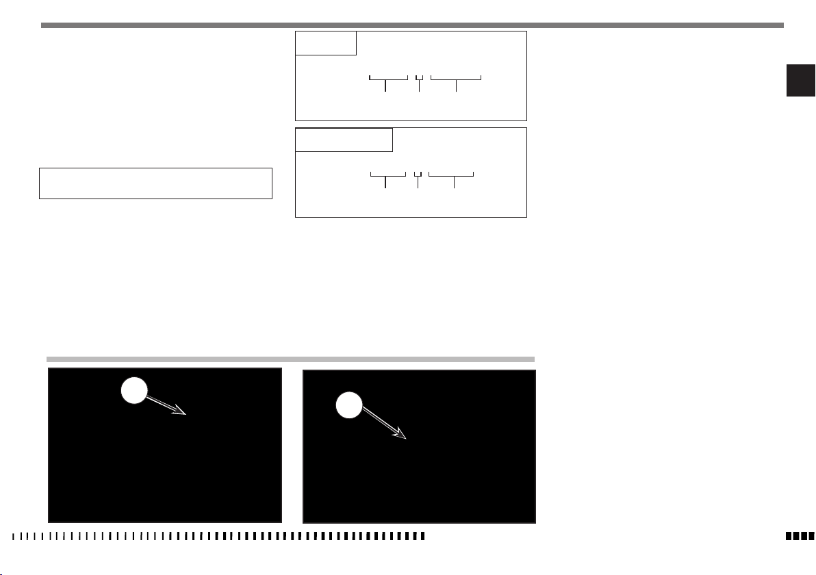
FRAME NUMBER
VEHICLE IDENTIFICATION NUMBER (V.I.N.)
The full 17 digit serial, or Vehicle Identification Number, is
stamped on the steering head tube (R.H. side).
(l) = Model designation
(▲) = Model Year (2013)
♦
) = Progressive no.
(
TC 250R
ZKHA300AADV050001
EN
(l) (▲) (♦)
TC 250R - USA
ZKHTC253#DV000001
(l) (▲) (♦)
1. Frame serial number
1
2. Engine serial number
2
SPECIFICATIONS - OPERATION - MAINTENANCE
EN - 5
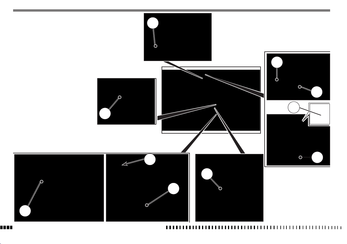
CONTROLS LOCATION
1. Front brake lever
2. Throttle twistgrip
3. ENIGINE STOP button (engine stop)
4. Kick start pedal
5. Clutch control lever
6. Starting device
7. Fuel tank ller cap
8. Gear shift pedal
9. Rear brake control pedal
10. Master cylinder
7
2
1
3
4
8
SPECIFICATIONS - OPERATION - MAINTENANCE
EN - 6
10
5
6
9

ENGINE
TECHNICAL DATA
Type..................................................... single cylinder, 4 stroke
Cooling ............................................................................ liquid
Bore ...............................................................3,11 in. (79 mm)
Stroke ......................................................... 2.00 in. (50,9 mm)
Displacement ......................................15,22 cu. in. (249,5 cm
Compression ratio ...........................................................13,6:1
Starting...................... kick start (with automatic decompressor)
TIMING SYSTEM
Type........................ 4 titanium valves, controlled by twin finger
follower type camshafts, mixed chain/gear drive system
CLUTCH
Type.....................oil bath multiple disc clutch, hydraulic control
TRANSMISSION
Type.....................................................constant mesh gear type
Transmission ratio
3
1st gear. ......................................................... 2,142 (z 30/14)
)
2nd gear ......................................................... 1,750 (z 28/16)
3rd gear ........................................................1,450 (z 29/26)
4th gear. .........................................................1,227 (z 27/22)
5 th gear. ........................................................1,041 (z 25/24)
SECONDARY DRIVE
Transmission sprocket- Rear wheel sprocket ............... Z 13- Z 50
FRONT BRAKE
Type......... fixed disc Ø 10.23 in. (Ø 260 mm) “Wave” type with
hydraulic control and floating caliper
REAR BRAKE
Type.... floating disc, Ø 9.45 in. (Ø 240 mm) “Wave” type with
hydraulic control and floating caliper
RIMS
Front .......................................................in light alloy: 1,6x21”
Rear......................................................in light alloy: 1,85x19”
TIRES
Front ................................................................... 80/100 x 21”
Rear......................................................................100/90x19”
EN
Valve clearance (with engine cold)
Intake ....................................................... 0,006 in. (0,15 mm)
Exhaust .....................................................0,008 in. (0,20 mm)
LUBRICATION
Type... wet crankcase, lobe pump and cartridge and mesh filters
IGNITION
Type ...........Electronic, inductive discharge, with adjustable
advance (digital control)
Spark plug type ...................................................NGK CR9EIA-9
Spark plug gap ......................... 0.031÷0,035 in. (0,8÷0,9 mm)
FUEL SYSTEM
Type......................................................Electronic injection feed
PRIMARY DRIVE
Drive pinion gear- Clutch ring gear ........................... Z 17- Z 54
Transmission ratio ............................................................3,176
Transmission ratio ............................................................3,846
FINAL RATIOS
1st gear .........................................................................26,180
2nd gear ........................................................................21,380
3rd gear ........................................................................17,715
4th gear .........................................................................14,994
5th gear .........................................................................12,726
FRAME
Type........Steel single tube cradle (roud, rectangular, ellipsoidal
tubes); light alloy rear frame
FRONT SUSPENSION
Type ”Upside-down” telescopic hydraulic front fork with advanced
axle (adjustable in compression and rebound stroke); stanchions
tubes Ø 1.89 in. (Ø 48 mm)
Legs axis stroke ........................................... 11.8 in. (300 mm)
REAR SUSPENSION
Type................progressive with hydraulic single shock absorber
Wheel stroke ............................................... 11.6 in. (296 mm)
SPECIFICATIONS - OPERATION - MAINTENANCE
Cold tire pressure
Front ................................................................0,9÷1,0 Kg/cm
Rear.................................................................0,8÷0,9 Kg/cm
EN - 7
2
2

DIMENSION, WEIGHT, CAPACITY
Wheelbase ............................................... 57.87 in. (1460 mm)
Overall length ............................................ 87.2 in. (2215 mm)
Overall width ............................................. 32.30 in. (820 mm)
TABLE FOR LUBRICATION, SUPPLIES
Engine, gearbox and primary drive lubricating oil
CASTROL POWER 1 RACING 10W-50
Engine coolant
CASTROL MOTORCYCLE COOLANT
Overall height .......................................... 50.79 in. (1305 mm)
Saddle height .............................................38.78 in. (985 mm)
Minimum ground clearance ........................ 11.42 in. (325 mm)
Kerb weight, without fuel ........................ 222,64 lb. (101,2 kg)
Fuel tank capacity .............................................. Imp. Gall. 1.43
U.S. Gall. 1.72
6,5 l
Coolant capacity ..............................................0.79 Imp. Quarts
0.95 U.S. Quarts
900 cc
Transmission oil
Oil and oil filter replacement .......................... Imp. Quarts 0.79,
U.S. Quarts 0.95
900 cc
Oil replacement ............................................... Imp. Quarts 0.75
U.S. Quarts 0.90
850 cc
Brake system fluid
CASTROL RESPONSE SUPER DOT 4
Clutch fluid
CASTROL RESPONSE SUPER DOT 4
Grease lubrication
CASTROL PASTE TA GREASE
Final drive chain lubrication
CASTROL CHAIN LUBE RACING
Front fork oil
Kayaba KHL15-11
Electric contact protection
CASTROL METAL PARTS CLEANER
CASTROL MOTORCYCLE DWF
Fillers for radiator
AREXONS TURAFALLE LIQUIDO
SPECIFICATIONS - OPERATION - MAINTENANCE
EN - 8
CONTROLS
FUEL COCK
Fuel cock is not tted on this model.
SIDE STAND
These models have a side stand (1) on the left side of
the motorcycle.
WARNING*: The stand is designed to support the weight of the MOTORCYCLE ONLY. Do
not sit on the motorcycle using the stand for
support as this could cause structural failure
to the stand and could cause serious bodily
injury.
FUEL
Recommended fuel: premium grade unleaded fuel. (R.O.N. 96
÷ 98).
WARNING*: Gasoline is extremely flammable and can be explosive under certain conditions. Always stop the engine and do not
smoke or allow flames or sparks in the area
where the motorcycle is refueled or gasoline
is stored.
WARNING*: Do not overfill the tank. After refueling, make sure the tank cap (2) is closed
securely.
2
COLD START
The motorcycle is equipped with a knob (1) positioned on throttle body for cold start. Pull the knob towards the outside to activate the starter, and on the opposite direction to deactivate it.
1
EN
1
SPECIFICATIONS - OPERATION - MAINTENANCE
EN - 9
THROTTLE CONTROL
The throttle knob (1), is located on the right hand side of the
handlebar. The position of the throttle control can be adjusted
by loosening the two fastenig screws (A).
CAUTION
Do not forget to tighten the screws (A) after
the adjustment.
FRONT BRAKE CONTROL
The brake control lever (2) is located on the right hand side of
the handlebar. The position of the throttle control can be adjusted by loosening the two fastenig screws (B).
CAUTION
Do not forget to tighten the screws (B) after
the adjustment.
CLUTCH CONTROL
The hydraulic clutch control lever (3) is located on the left-hand
side of the handlebar and is protected against dirt with a rubber guard.
The position of the clutch control on handlebar can be adjusted
by loosening the retaining screws (C).
CAUTION
Do not forget to tighten the screws after the
adjustment.
ENGINE STOP BUTTON
On the left side of the handlebar, near the clutch control, is located the engine stop button.
B
A
1
2
SPECIFICATIONS - OPERATION - MAINTENANCE
EN - 10
C
3
1
REAR BRAKE CONTROL
The rear brake control (1) is placed on the right-hand side of
the motorcycle.
GEAR SHIFT CONTROL
The lever (1) is placed on the left-hand side of the engine. The
operator must release the lever after each gear change to allow
it to return to its central position before another gear
change can be made.
Neutral position (N) is between first (low) and second gears.
First gear is engaged by pushing the lever downwards; all the
other gears are engaged, by pushing the lever upwards.
The position of the gear shift lever on the shaft can be varied
by:
- loosening screw;
- pulling lever out;
- placing lever in new position on the shaft when the operation
is over tighten the screw and then tightening the screw.
CAUTION*: Do not shift gears without disengaging the clutch and closing the throttle. The
engine could be damaged by overspeed and
shock.
N: Neutral
5
4
N
3
2
WARNING*: Do not downshift when traveling
at a speed that would force the engine to
overrev in the next lower gear, or cause the
rear wheel to lose traction.
EN
1
1
1
SPECIFICATIONS - OPERATION - MAINTENANCE
EN - 11

RIDING
BEFORE EVERY RIDE MAKE FOLLOWING CHECKS
WARNING!
Before each ride, to prevent accidents or failures during ride,
make sure to go through following list.
1. Check all fluids
A. Engine-transmission oil level
B. fuel level
C. coolant level
Make sure all caps are properly adjusted.
WARNING*: Don’t remove radiator cap when
hot!
2. Check all controls
A. Throttle handgrip
B. Clutch lever
Make sure cables are not damaged and turn smoothly.
3. Check brakes
Look for brake fluid leaks and worn hoses. Check for proper
functioning.
4. Check suspensions
Compress fork and rear suspensions. Look for oil leaks and
ensure proper functioning.
5. Check wheels
Check spokes and look for worn bearings.
Check rims and tyres.
Check tyre pressure.
6. Check chain rollers and sprockets
Check wear on chain rollers and sprockets
Ensure chain is correctly adjusted and lubricated.
7. Check air filter and intake system
Check that air filter is clean
Check all rubber connections and clamps.
8. Check exhaust system
Check hook up, look for cracks
Check muffler.
9. Check torque
A. Spark plug
B. General check of torque
10. Check steering action
Check bearing play.
WARNING*: Failure to perform these checks
every day before you ride may result in serous damage or a severe accident.
.
RUNNING IN
Before using the motorcycle for sporting activities run in the
engine for two hours at least to increase the life and the performance of the engine.
During the first half-hour of driving we advise keeping a low
speed and avoiding sudden accelerations. Never open the throttle fully.
Change the oil and carry out all the necessary maintenance operations. After the first half-hour of driving, lightly increase the
rev number, but never run the engine at full throttle. Never keep
low speeds when the high gears are inserted.
Slowly drive the motorcycle for two hours before using it for
sporting activities.
CHECKS DURING RUNNING
- SPOKE TENSION OF WHEELS;
- TIGHTENING OF WHEELS;
- FORK PIN TIGHTENING;
- CHAIN ADJUSTMENT;
- STEERING BEARING PLAY;
- HANDLEBAR TIGHTENING;
- ENGINE GRIP TO FRAME;
- SUCTION FITTING GRIP;
- HEAD AND CYLINDER NUTS GRIP.
SPECIFICATIONS - OPERATION - MAINTENANCE
EN - 12
 Loading...