

Page 1
ST724
1.1996
Spare Parts
Piéces Dètachées
Owner's Manual 601 00 17-36
Reference No. 337209 05/09/95
Page 2

SAFETY RULES
ALWAYS DISCONNECT SPARK PLUG WIRE AND PLACE WIRE WHERE IT
CANNOT CONTACT SPARK PLUG TO PREVENT ACCIDENTAL STARTING
WHEN SETTING-UP, TRANSPORTING, ADJUSTING OR MAKING REPAIRS.
IMPORTANT
SAFETY STANDARDS REQUIRE OPERATOR PRESENCE CONTROLS TO MINIMIZE THE RISK OF INJURY.
YOUR SNOW THROWER IS EQUIPPED WITH SUCH CONTROLS. DO NOT ATTEMPT TO DEFEAT THE
FUNCTION OF THE OPERATOR PRESENCE CONTROL UNDER ANY CIRCUMSTANCES.
BEFORE USE
● Read the Owner’s Manual carefully. Be thoroughly
familiar with the controls and the proper use of the snow
thrower. Know how to stop the snow thrower and
disengage the controls quickly.
● Do not operate the snow thrower without wearing
adequate winter outer garments. Wear footwear that will
improve footing on slippery surfaces.
● Keep the area of operation clear of all persons, particularly
small children, and pets.
● Thoroughly inspect the area where the snow thrower is
to be used and remove all doormats, sleds, boards,
wires, and other foreign objects.
● Use extension cords and receptacles as specified by the
manufacturer for all snow throwers with electric drive
motors or with factory-installed or optional starting
motors.
● Use only attachments and accessories approved by the
manufacturer of the snow thrower (such as electric
starter kits, etc.).
● Never operate the snow thrower without good visibility
or light. Always be sure of your footing, and keep a firm
hold on the handles. Walk; never run.
● This snow thrower is for use on sidewalks, driveways,
and other ground level surfaces. Do not attempt to
clear on steep sloping surfaces. DO NOT USE
SNOW THROWER ON SURFACES ABOVE GROUND
LEVEL such as roofs of residences, garages, porches
or other such structures or buildings.
● Check all bolts at frequent intervals for proper tightness
to be sure the snow thrower is in safe working condition.
● Disengage clutch and shift into neutral before starting
the engine.
● Let engine and snow thrower adjust to outdoor
temperatures before starting to clear snow.
FUEL SAFETY
● Handle fuel with care; it is highly flammable.
● Use an approved fuel container.
● Check fuel supply before each use, allowing space for
expansion as the heat of the engine and/or sun can
cause fuel to expand.
● Fill fuel tank outdoors with extreme care. Never fill fuel
tank indoors.
● Replace fuel tank cap securely and wipe up spilled fuel.
● Never remove fuel tank cap or add fuel to a running
engine or hot engine.
● Never store fuel or snow thrower with fuel in the tank
inside a building where fumes may reach an open flame
or spark.
OPERATING SAFETY
● Do not put hands or feet near or under rotating parts.
Keep clear of the discharge opening at all times.
● Never operate the snow thrower without proper guards,
plates or other safety protective devices in place.
● Never allow children or young teenagers to operate the
snow thrower and keep them away while it is operating.
never allow adults to operate the snow thrower without
proper instruction.
● Always wear safety glasses or eye shields during operation
or while performing an adjustment or repair to protect eyes
from foreign objects that may be thrown from the snow
thrower.
● Exercise extreme caution when operating on or crossing
gravel drives, walks, or roads. Stay alert for hidden hazards
or traffic.
● Exercise caution to avoid slipping or falling, especially when
operating in reverse or backing up.
● Do not clear snow across the face of slopes. Exercise
caution when changing direction on slopes. Do not attempt
to clear steep slopes.
● Never operate the snow thrower without proper guards,
plates or other safety protective devices in place.
● Never operate the snow thrower near glass enclosures,
automobiles, window wells, drop-offs, and the like without
proper adjustment of the snow discharge angle. Keep
children and pets away.
● Never operate the snow thrower at high transport speeds on
slippery surfaces. Look behind and use care when backing.
● Do not run the engine indoors, except when starting the
engine and for transporting the snow thrower in or out of the
building. Open the outside doors; exhaust fumes are
dangerous (containing CARBON MONOXIDE, an
ODORLESS and DEADLY GAS).
● Take all possible precautions when leaving the snow thrower
unattended. Disengage the auger/impeller, stop engine,
and remove key.
● Do not overload the machine capacity by attempting to clear
snow at too fast a rate.
● Never direct discharge at bystanders or allow anyone in
front of the unit.
2
Page 3
SAFETY RULES
SAFE STORAGE
● Always refer to Owner’s Manual instructions for important
details if the snow thrower is to be stored for an extended
period.
● Disengage power to the auger/impeller when snow thrower
is transported or not in use.
● Never store the snow thrower with fuel in the fuel tank
inside a building where ignition sources are present such
as hot water and space heaters, clothes dryers, and the
like. Allow the engine to cool before storing in any
enclosure.
REPAIR/ADJUSTMENTS SAFETY
● After striking a foreign object, stop the engine and remove
the wire from the spark plug, or disconnect the cord from
electric motor. Thoroughly inspect the snow thrower for
any damage, and repair the damage before restarting and
operating the snow thrower.
● If the snow thrower should start to vibrate abnormally,
stop the engine (or electric motor) and check immediately
for the cause. Vibration is generally a warning of trouble.
● STOP THE ENGINE (OR ELECTRIC MOTOR)
WHENEVER YOU LEAVE THE OPERATING POSITION,
BEFORE UNCLOGGING THE AUGER/IMPELLER
HOUSING OR DISCHARGE GUIDE, AND WHEN
MAKING ANY REPAIRS, ADJUSTMENTS, OR
INSPECTIONS. REMOVE WIRE FROM SPARK PLUG
OR DISCONNECT CORD FROM ELECTRIC MOTOR.
● When cleaning, repairing, or inspecting, make certain the
auger/impeller and all moving parts have stopped.
Disconnect the spark plug wire and keep the wire away
from the plug to prevent accidental starting.
● Never attempt to make any adjustments while the engine
is running (except when specifically recommended in
this manual or the engine manual).
● Maintain or replace safety and instruction labels, as
necessary.
● Run the snow thrower a few minutes after throwing snow
to prevent freeze-up of the auger/impeller.
LOOK FOR THIS SYMBOL TO POINT OUT IMPORTANT SAFETY PRECAUTIONS. IT MEANS-ATTENTION!!! BECOME ALERT!!! YOUR SAFETY IS INVOLVED.
California Proposition 65 WARNING!
The engine exhaust from this product contains chemicals known to the State of
California to cause cancer, birth defects or other reproductive harm.
3
Page 4

OWNER'S INFORMATION
Record the following information about your unit so that you will be able to provide it in case of loss or theft.
MODEL NUMBER:
PURCHASE DATE:
DEALER'S NAME AND ADDRESS:
CITY:
SAFETY RULES...................................................... 2,3
OWNER'S INFORMATION.........................................4
TABLE OF CONTENTS ............................................. 4
INTERNATIONAL SYMBOLS ....................................5
ILLUSTRATIONS ..................................................6-15
ASSEMBLY .........................................................16-18
Contents Of Shipping Carton .................................. 16
Tools Required For Assembly.................................16
To Remove Snow Thrower From Carton ................17
To Set The Skid Height........................................... 17
To Install The Crank Assembly ...............................17
To Install The Shift Rod .......................................... 18
To Check/Adjust Clutch Control Cables..................18
To Install Chute Assembly to Chute Flange............18
To Install Remote Chute Deflector Knob ................18
Drift Cutter Assembly .............................................. 18
OPERATION ........................................................19-21
How To Use Your Snow Thrower ........................... 19
Before Starting The Engine................................19-20
To Stop Engine ....................................................... 20
To Start Engine ....................................................... 20
Snow Throwing Tips ............................................... 21
MAINTENANCE...................................................22-23
Lubrication Chart..................................................... 11
Service Chart .......................................................... 22
/
/
CODE NO.:
STATE: TELEPHONE:
(Enter complete 8 digit number from model plate on unit)
SERIAL NO.:
TABLE OF CONTENTS
General Recommendations .................................... 22
Lubrication .........................................................22-23
Spark Plug............................................................... 23
SERVICE AND ADJUSTMENTS.........................24-27
To Adjust Skids Height............................................ 24
To Adjust Scraper Bar............................................. 24
To Adjust Clutch Control Cables............................. 24
To Adjust Belts
Auger Drive Belt...............................................24-25
Traction Drive Belt ................................................ 25
To Replace Belts
Auger Drive Belt................................................... 25
Traction Drive Belt ...............................................25
To Adjust The Belt Guides .................................25-26
To Adjust The Friction Wheel..................................26
To Replace Friction Wheel......................................26
To Replace Auger Shear Bolt ................................. 26
To Adjust Carburetor............................................... 27
To Adjust Or Replace The Spark Plug....................27
STORAGE ................................................................ 28
TROUBLE SHOOTING............................................. 29
REPAIR PARTS ..................................................30-45
WARRANTY .............................................. Back Cover
NOTICE: Photographs and illustrations in this manual may not show your model but are for reference only.
4
Page 5
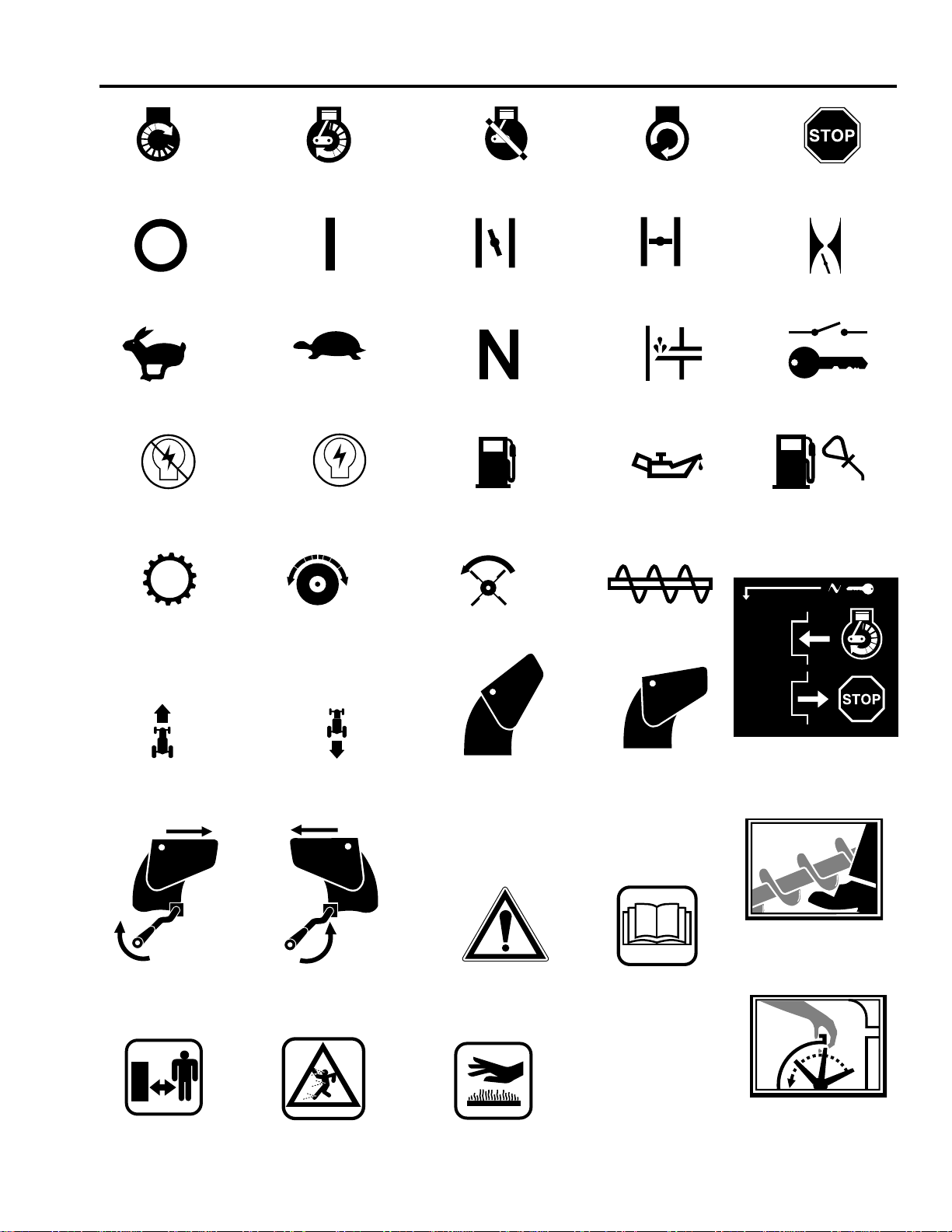
INTERNATIONAL SYMBOLS
ENGINE START ENGINE RUN
ENGINE STOP
FAST
IGNITION OFF
TRANSMISSION
ON
SLOW
IGNITION ON
DRIVE CLUTCH
OFF ELECTRIC
START
CHOKE OFF CHOKE ON THROTTLE
NEUTRAL
FUEL
AUGER CLUTCH
PRIMER BUTTON
OIL
AUGER/
COLLECTOR
FUEL OIL MIXTURE
STOP
IGNITION KEY
FORWARD
DISCHARGE
CHUTE -
TURN RIGHT
KEEP
BYSTANDERS
AWAY
REVERSE
DISCHARGE
CHUTE -
TURN LEFT
BEWARE OF
THROWN
OBJECTS
DISCHARGE
CHUTE - UP
POSITION
CAUTION
HOT SURFACE
5
DISCHARGE
CHUTE - DOWN
POSITION
READ OWNER'S
MANUAL
IGNITION KEY INSERT
TO RUN PULL OUT TO
STOP
KEEP HANDS,
FEET, AND
CLOTHING AWAY!
DO NOT USE
HANDS TO UN-
CLOG DISCHARGE
CHUTE.
Page 6
1
1
4
2
3
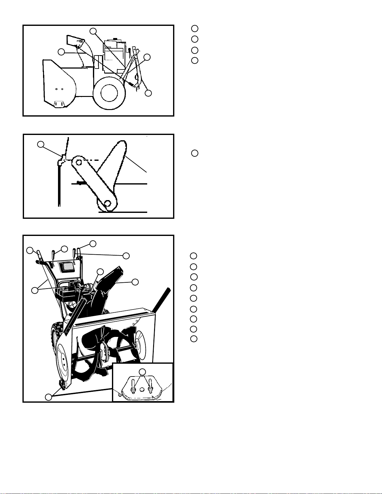
LOWER HANDLE/ELEMENT INFERIEUR DE MANCHERON
2
CLUTCH CABLE/CABLE D'EMBRAYAGE
3
UPPER HANDLE ASSEMBLY/ELEMENT SUPERIEUR DE MANCHERON
4
CRANK ASSEMBLY/MANIVELLE
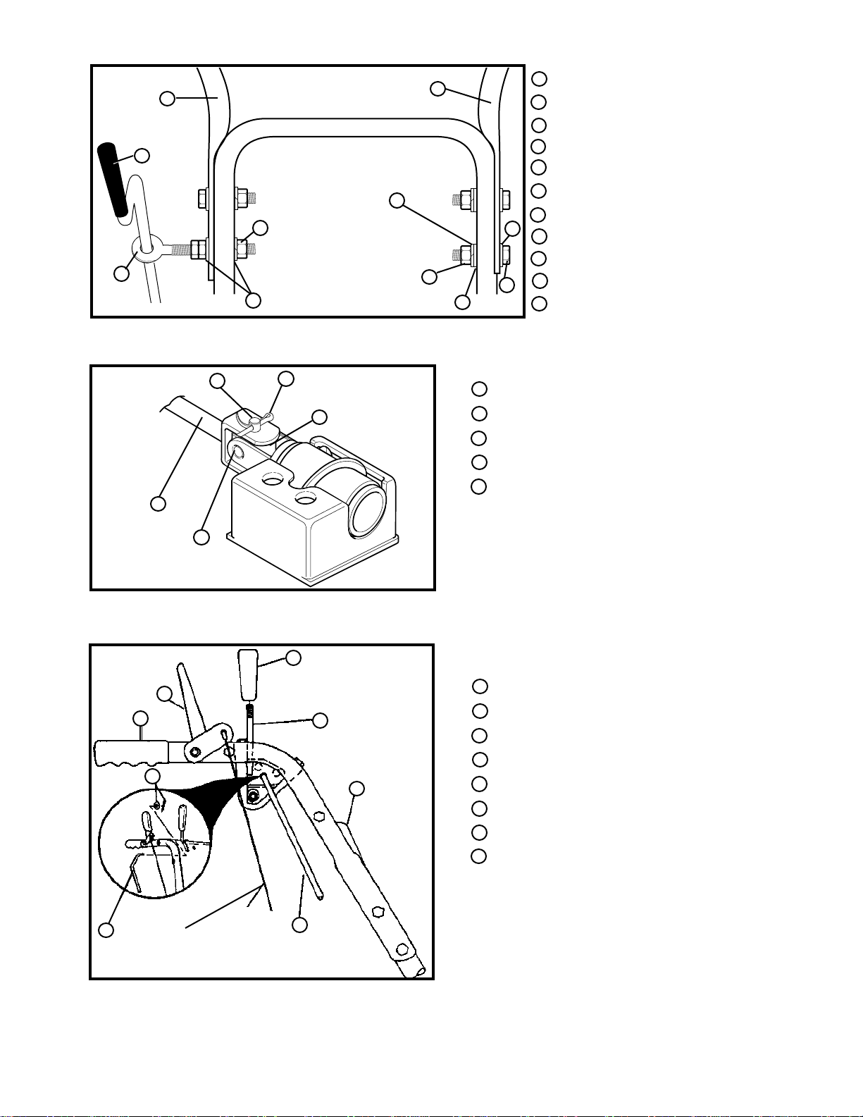
III.1
1
1
"Z" FITTING/RACCORD EN Z
III. 2
1
5
2
8
3
9
4
6
7
1
AUGER CLUTCH LEVER/LEVIER D'EMBRAYAGE DE VIS SANS FIN
SHIFTER LEVER/LEVIER DE CHANGEMENT DE VITESSE
2
TRACTION CLUTCH LEVER/LEVIER D'EMBRAYAGE DE TRACTION
3
4
CRANK ASSEMBLY/MANIVELLE
CLUTCH CABLE/CABLE D'EMBRAYAGE
5
CHUTE DEFLECTOR/DEFLECTEUR DE GOULOTTE
6
7 MOUNTING NUTS/ECROUS DE FIXATION
8
HEIGHT ADJUST SKID/PATIN A HAUTEUR REGLABLE
9
REMOTE CHUTE DEFLECTOR LEVER/LEVIER DU DÉFLECTEUR
DE LA GOULOTTE
III. 3
6
Page 7
1
1
2
4
3
5
6
8
10
11
9
LEFT HANDLE/COTE DROIT DU MANCHERON
2 CRANK/MANIVELLE
EYE BOLT/BOULON A OEIL
3
3/8 INCH NYLON LOCKNUT/RONDELLE GROWER 3/8 PO.
4
3/8 INCH FLATWASHERS/RONDELLE PLATE 3/8 PO.
5
RIGHT HANDLE/COTE GAUCHE DU MANCHERON
6
3/8 INCH FLATWASHER/RONDELLE PLATE 3/8 PO.
7
7
8 3/8 INCH FLATWASHER/RONDELLE PLATE 3/8 PO
3/8 X 2 INCH BOLT/BOULON 3/8 X 2 PO
9
10 3/8 INCH NUT/ECROU 3/8 PO
11
3/8 INCH LOCKWASHER/RONDELLE GROWER 3/8 PO
III.4
1
4
5
2
3
CLEVIS PIN/GOUPILLE FENDUE
1
2 COTTER PIN/GOUPILLE FENDUE
3
UNIVERSAL JOINTJOINT DE CARDAN
4
CRANK ROD ASSEMBLY/TIGE DE MANIVELLE
5
DRILLED PIN/AXE FORE
III.5
1
SHIFTER LEVER KNOB/POMMEAU DE LEVIER DE CHANGEMENT
2
4
8
3
5
1
DE VITESSE
CLUTCH LEVER/LEVIER D'EMBRAYAGE
2
SHIFTER LEVER/LEVIER DECHANGEMENT DE VITESSE
3
UPPER HANDLE/ELEMENT SUPERIEUR DE MANCHERON
4
5
CONTROL PANEL/TABLEAU DE BORD
SHIFT ROD/TIGE DE CHANGEMENT DE VITESSE
6
7
CLUTCH CABLE/CABLE D'EMBRAYAGE
WASHER & COTTER PIN/RONDELLE & GOUPILLE FENDUE
8
7
6
III.6
7
Page 8
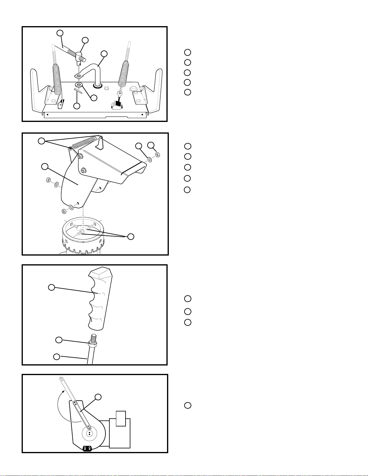
1
2
1
3
4
5
SHIFT ROD/TIGE DE CHANGEMENT DE VITESSE
TRUNION NUT/ECROU A PIVOT
2
SPEED ROD/TIGE DE SELECTION DE VITESSE
3
WASHER/RONDELLE
4
COTTER PIN/GOUPILLE FENDUE
5
III.7
1
2
5
3
4
SPRING BRACKETS/SUPPORT DU RESSORT
1
CHUTE EXTENSION/GOULOTTE
2
NUT/ECROU
3
4 FLATWASHER/RONDELLE PLATE
5
CARRIAGE BOLTS/BOULON
III. 8
1
KNOB/POMMEAU EN PLASTIQUE POINTANT VERS L'AVANT
1
HEX NUT/ÉCROU HEXAGONAL
2
3 LEVER/LEVIER DE VITESSE
2
3
III. 8-A
1
1
DRIFT CUTTERS/COUTEAUX VERTICAUX
III. 8-B
8
Page 9
READ THIS OWNER’S MANUAL AND SAFETY RULES BEFORE OPERATING YOUR SNOW THROWER. Compare the illustrations with your
snow thrower to familiarize yourself with the location of various controls and adjustments. Save this manual for future reference./
FAMILIARISATION AVEC LE CHASSE-NEIGE A TURBINE. LISEZ LE PRESENT MANUEL D'UTILISATION ET LES REGES DE SECURITE
AVANT D'UTILISER LE CHASSE-NEIGE. Comparez les illustrations à votre chasse neige pour vos familiariser avec l'emplacement des
diverses commandes et les réglages. Conservez ce manuel pour vous y référer par la suite.
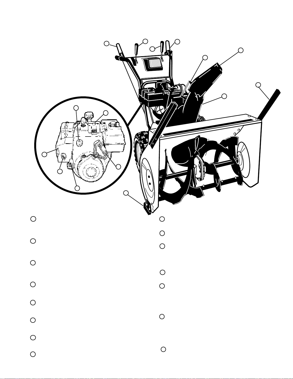
This snow thrower conforms to the safety
standards of the American National Stan-
1
3
14
2
5
4
dards Institute. /Le chasse-neige est
conforme aux normes de sécurité de l'Institut
National Américain de Normalisation.
15
6
11
13
8
9
10
12
AUGER CLUTCH LEVER - Starts and stops the auger and
1
7
impeller (snow gathering and throwing)./ LEVIER
D'EMBRAYAGE DE VIS SANS FIN - Met en marche et arrête
la vis sans fin et le rotor (ramassage et éjection de la neige)
TRACTION CLUTCH LEVER - Propels the snow thrower
2
forward and in reverse./LEVIER D'EMBRAYAGE DE TRACTION - Commande la propulsion du chasse-neige en marches
avant et arrière.
SPEED SHIFTER LEVER - Selects the speed of the snow
3
thrower (6 speeds forward and 2 speeds reverse)./LEVIER
DE CHANGEMENT DE VITESSE - Sélectionne la vitesse du
chasse-neige (6 rapports en marche avant et 2 en marche
arrière)
4
CRANK ASSEMBLY - Changes the direction of snow throw-
ing through the discharge chute./MANIVELLE - Change la
direction d'éjection de la neige par la goulotte.
5
CHUTE DEFLECTOR - Changes the distance the snow is
thrown./DEFLECTEUR DE GOULOTTE - Change la distance
à laquelle la neige est projetée.
6
DISCHARGE CHUTE - Changes the direction the snow is
thrown./GOULOTTE D'EJECTION - Change la direction dans
7
laquelle la neige est projetée.
HEIGHT ADJUST SKIDS - Adjusts the ground clearance of
the auger housing./PATINS A HAUTEUR REGLABLE -
8
Règlent la garde au sol du carter de vis sans fin.
III.9
IGNITION KEY - Must be inserted to start the engine./CLE DE
9
CONTACT - Elle doit être enfoncée pour faire démarrer le
moteur.
RECOIL STARTER HANDLE - Starts the engine manually./
10
POIGNEE DE DEMARREUR-LANCEUR - Fait démarrer le
moteur manuellement.
11
CHOKE CONTROL - Used to start a cold engine./COMMANDE
DE STARTER - Sert à faire démarrer un moteur froid.
PRIMER BUTTON - Injects fuel directly into the carburetor
manifold for fast starts in cold weather./BOUTON DE
TITALLATEUR - Injecte du carburant directement dans la
12
tubulure d'admission du carburateur pour accélérer le
démarrage par temps froid.
13
THROTTLE CONTROL - Controls the engine speed./
COMMANDE DES GAZ - Commande le régime du moteur.
ELECTRIC STARTER BUTTON - Used to start the engine
using the 120V electric starter/BOUTON DE DEMARREUR
ELECTRIQUE - Utilisé pour faire démarrer le moteur au
moyen du démarreur électrique 120V.
REMOTE CHUTE DEFLECTOR LEVER - Push forward to
14
discharge snow high and far. Pull remote lever back to
discharge snow down./LEVIER DU DÉFLECTEUR DE LA
GOULOTTE - Ce déflecteur permet de modifier la distance de
projection de la neige. Relever le déflecteur pour projeter la
neige plus loin ou le descendre pour l'inverse.
DRIFT CUTTERS - Cuts a path through snow drifts taller than
15
unit./COUTEAUX VERTICAUX - Coup à travers neige
couteaux hauter que unité.
9
Page 10
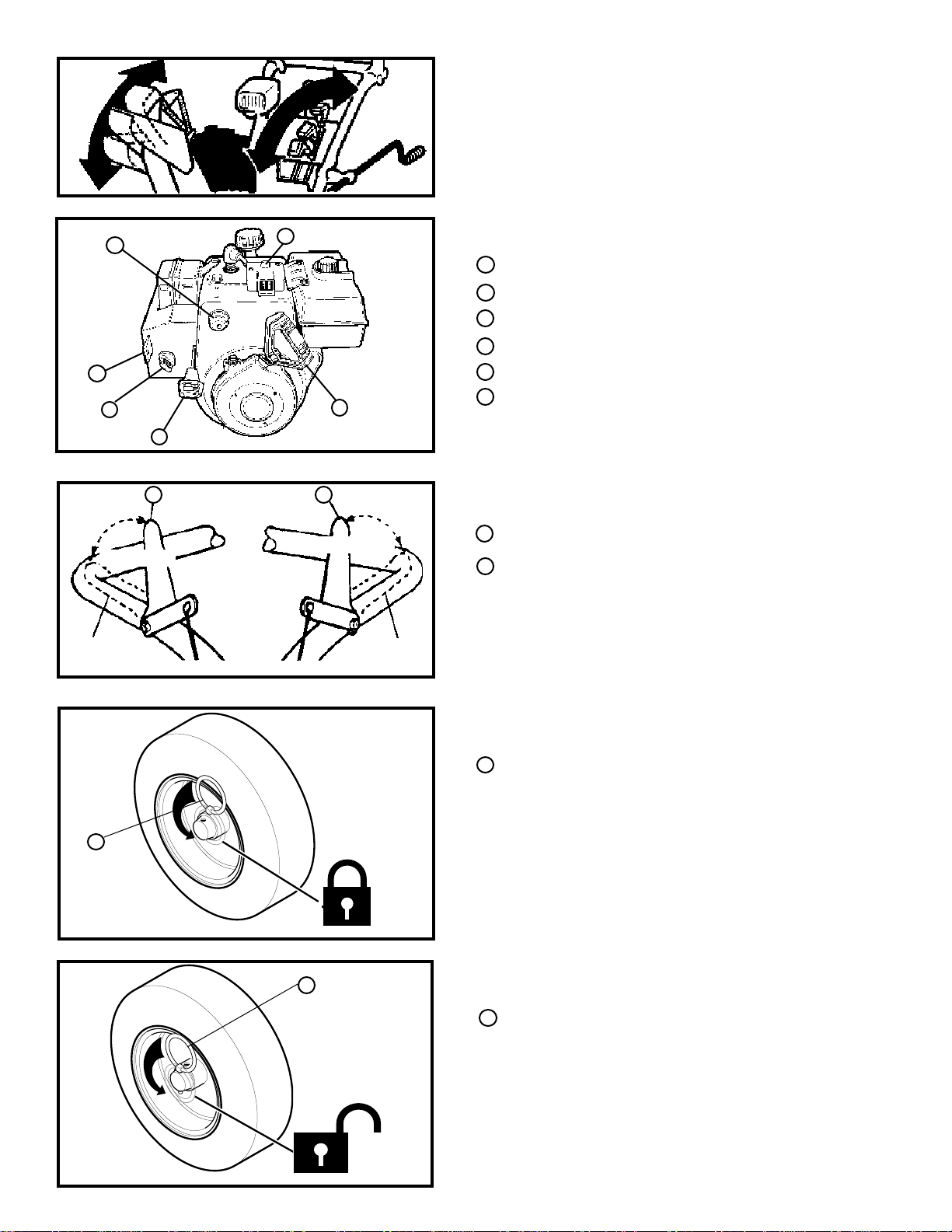
III. 10
1
2
3
OFF/ARRET
ON/MARCHE
LEFT
HAND/
COTE GAUCHE
6
4
III.11
1 2
III.12
5
OFF/ARRET
ON/MARCHE
HAND/COTE
DROIT
RIGHT
PRIMER BUTTON/BOUTON DE TITILLATEUR
1
2 IGNITION KEY/CLE DE CONTACT
3
CHOKE CONTROL/COMMANDE DE STARTER
THROTTLE CONTROL/COMMANDE DES GAZ
4
5
RECOIL STARTER HANDLE/POIGNEE DE DEMARREUR-LANCEUR
ELECTRIC STARTER BUTTON/BOUTON DE DEMARREUR
6
ELECTRIQUE
1
TRACTION CLUTCH LEVER OFF/LEVIER D'EMBRAYAGE DE
TRACTION EN POSITION D'ARRET
AUGER CLUTCH LEVER OFF/LEVIER D'EMBRAYAGE DE VIS SANS
2
FIN
LOCKED/POSITION
VERROUILLEE
1
2-WHEEL DRIVE/TRACTION A 2 ROUES MOTRICES
III.13
1
UNLOCKED
POSITION/POSITION
DEVERROUILLEE
SINGLE WHEEL DRIVE/TRACTION A 1 ROUE MOTRICE
III.14
1
KLICK PIN/GOUPILLE "KLICK"
1 KLICK PIN/GOUPILLE "KLICK"
10
Page 11
1
/NIVEAU
ADMISSIBLE
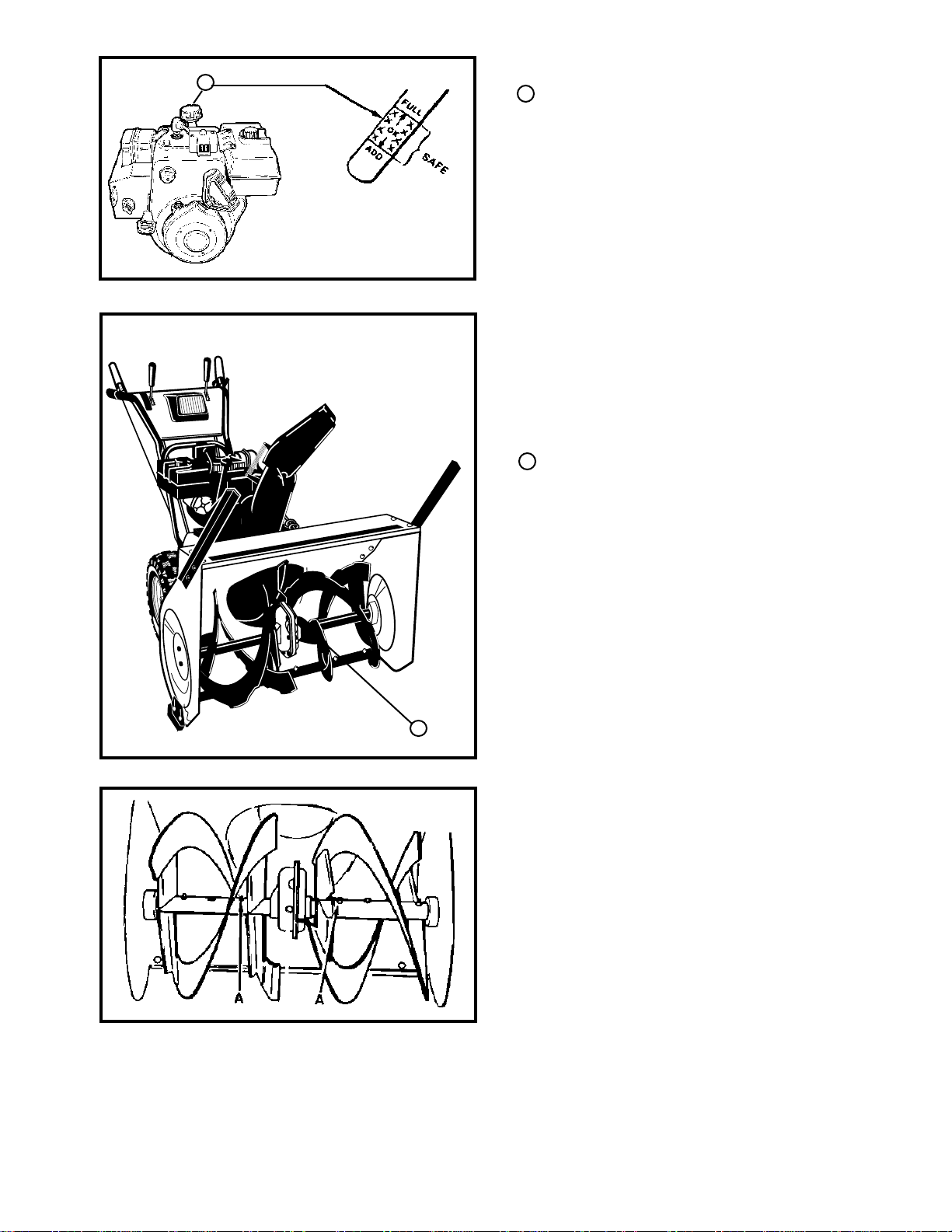
NOTE: OIL LEVEL MUST BE BETWEEN
FULL AND ADD MARK/REMARQUE: LE
NIVEAU D'HUILE DOIT SE TROUVER
ENTRE LES REPERES FULL (PLEIN) ET
ADD (REMPLIR)
1 OIL FILL CAP/DIPSTICK/BOUCHON DE REMPLISSAGE/JAUGE DE
NIVEAU D'HUILE
III.15
LUBRICATION CHART/TABLEAU DE GRAISSAGE
1
Lubricate the Auger Shaft. Coat with a clinging type grease such as
Lubriplate./Graissez l'arbre de vis sans fin. Appliquez une couche de
graisse de type adhésif telle que la graisse "Lubriplate."
III.16
III.17
1
11
Page 12
1
AXLE/ESSIEU
1
1
III.18
1
1
HEX SHAFT AND GEARS/ARBRE HEXAGONAL ET ENGRENAGES
2 FRICTION WHEEL/ROUE A FRICTION
3
2 GAP BETWEEN FRICTION WHEEL AND DISC DRIVE PLATE/
5
6
5
7
4
8
2
GEARS (REQUIRE NO LUBRICATION)/ENGRENAGES (N'EXIGEN
3
AUCUN GRAISSAGE
4
DISC DRIVE PLATE/DISQUE D'ENTRAINEMENT
GREASE ZERK/GRAISSEUR A PRESSION
5
6
ESPACE ENTRE ROUE A FRICTION ET DISQUE D'ENTRAINEMENT
7
BEARING ASSEMBLY/ROULEMENT
Point at which grease should be visible/Point auquel la graisse
8
doit être visible
III.19
1
SKID MOUNTING NUTS/ECROUS DE FIXATION DE PATIN
1
2
HEIGHT ADJUST SKIDS/PATIN A HAUTEUR REGLABLE
2
III.20
1
1
2
3
TRACTION DRIVE LEVER/LEVIER DE COMMANDE DE VIS SANS
FIN
"Z" FITTING/RACCORD "Z"
2
PLASTIC BUMPER/PLASTIQUE BUMPER
3
CONTROL LEVER MUST BE IN FULL FORWARD POSITION (Just
Contacting Plastic Bumper) WHEN CHECKING/
LE LEVIER DE COMMANDE DROIT ETRE POUSSE A FOND VERS
L'AVANT (Juste au contact du tampon-amortisseur plastique) LORS
DE LA VERIFICATION
III.21
12
Page 13

1
5
3
4
2
TRACTION DRIVE SPRING/RESSORT DE TRACTION
1
AUGER DRIVE SPRING/RESSORT DE COMMANDE DE VIS SANS FIN
2
3 SPRING/RESSORT
THREADED END/EXTREMITE FILETEE
4
LOCKNUT/CONTR-ECROU
5
III.22
DRIVE PULLEY/POULIE D'ENTRAINEMENT
1
2
3
4
1
AUGER IDLER PULLEY ENGAGED/GALET-TENDEUR DE
2
COMMANDE DE VIS SANS FIN ENCLENCHE
3
1/2 INCH DEFLECTION/FLEXION DE 13 MM (1/2 PO)
IMPELLER PULLEY/POULIE DE ROTOR
4
III.23
1
5
2
3
4
6
1
TRACTION DRIVE BELT/COURROIE DE COMMANDE DE
TRACTION
AUGER DRIVE BELT/POULIE DE COMMANDE DE TRACTION
2
3
BELT GUIDE (Right Hand)/GUIDE DE COURROIE (Côté droit)
4
BELT GUIDE (Left Hand)/GUIDE DE COURROIE (Côté gauche)
5
TRACTION DRIVE IDLER PULLEY/POULIE D'ENTRAINEMENT DE
VIS SANS FIN
AUGER IDLER PULLEY/GALET-TENDEUR DE COMMANDE DE
6
VIS SANS FIN
III.24
1
BELT COVER/PROTEGE-COURROIE
5/8 INCH FLATWASHER/RONDELLE PLATE 5/8 PO
2
1
1/4 X 1/2 INCH SELF TAPPING SCREW/VIS AUTOTARAUDEUSE
3
1/4X1/2 PO
III.25
2
3
13
Page 14

AUGER DRIVE PULLEY/POULIE D'ENTRAINEMENT DE VIS SANS
1
2
3
5
4
3
6
1
FIN
3/32 INCH/3/32 PO
2
BELT GUIDE (Right Hand)/GUIDE DE COURROIE (Côté droit)
3
BELT GUIDE (Left Hand)/GUIDE DE COURROIE (Côté gauche)
4
AUGER IDLER PULLEY ENGAGED/GALET-TENDEUR DE
5
COMMANDE DE VIS SANS FIN ENCLENCHE
6
IMPELLER PULLEY/POULIE DE ROTOR
III.26
3
4
(Bottom View)
III.27
III.28
> 3" <
1
4
2
1
2
1
BOTTOM PANEL/PANNEAU INFERIEUR
AUGER HOUSING/CARTER DE VIS SANS FIN
2
REMOVE TOP BOLTS (Each side)/RETIRER LES BOULONS
3
LOOSEN BOTTOM BOLTS (Each side)/DESSERRER LE
4
BOULONS
1 FRICTION WHEEL/ROUE A FRICTION
DISC DRIVE PLATE/DISQUE D'ENTRAINEMENT
2
2
1
TRUNION NUT/ECROU A PIVOT
3
4
5
1
SHIFT ROD/TIGE DE CHANGEMENT DE VITESSE
2
SPEED ROD/TIGE DE SELECTION DE VITESSE
3
WASHER/RONDELLE
4
5
COTTER PIN/GOUPILLE FENDUE
III.29
14
Page 15

1
4
6
2
3
LOCKWASHER/RONDELLE GROWER
1
FRICTION WHEEL/ROUE A FRICTION
2
BOLT/BOULON
3
5
3
NUT/ECROU
4
HEX SHAFT/ARBRE HEXAGONAL
5
HUB/MOYEU
6
4
1
III.30
1
2
3
5
4
6
MACHINE REPOSANT SUR L'EXTREMITE DU CARTER DE VIS SANS FIN
(UNIT STANDING ON AUGER HOUSING END)
III.31
1
FRICTION WHEEL/ROUE A FRICTION
HUB/MOYEU
2
HEX SHAFT/ARBRE HEXAGONAL
3
4 BEARING PLATES/PLAQUE D'APPUI
FASTENERS(screws, lockwashers, & nuts)/ATTACHE(Vis,
5
rondelle grower & ecrous)
AUGER HOUSING/CARTER DE VIS SANS FIN
6
1
SHEAR BOLT/BOULON DE SURETE A CISAILLER
1
2 SHEAR BOLT SPACER/RONDELLE D'ECARTEMENT POUR
3
2
BOULON DE SURETE A CISAILLER
3
LOCKNUT/CONTRE-ECROU
III.32
CARBURETOR/CARBURATEUR
1
IDLE ADJUSTING SCREW
1
(Close finger tight only)/VIS DE
2
REGLAGE DE RALENTI (La serrer à
la main seulement)
HIGH SPEED ADJUSTING SCREW
3
(Close finger tight only)/VIS DE REGLAGE
DE HAUT REGIME (La serrer à la main
2
4
3
seulement
4 BOWL DRAIN/VIDANGE DE
CUVE
.030 GAP/ECARTEMENT
1
DE 0,75 MM (0,030 PO)
1
III.34
III.33
15
Page 16

ASSEMBLY
CONTENTS OF SHIPPING
CARTON
1- Snow thrower completely assembled except for the
crank assembly, shift rod assembly and knob and
upper handle, which is in the folded down position.
1- Crank Assembly
1 - Spring for Remote Chute Return
1- Owner's Manual (Not Shown)
1- Parts Box Containing:
1 - Container of 5W30 Oil
1 - Electric Starter Cord 9.5 Ft. (if equipped with
electric start)
1 - Chute Assembly (may be assembled)
1 - Bag of Assembly parts containing:
1 - 3/8-16 x 2 Inch Hex Hd Screw
TOOLS REQUIRED FOR
ASSEMBLY
1 - Knife (to cut carton and plastic ties)
2 - 1/2 inch Wrenches (or adjustable wrenches)
2 - 9/16 inch Wrenches (or adjustable wrenches)
2 - 3/4 inch Wrenches (or adjustable wrenches)
1 - Pair Pliers or Screw Driver (to spread cotter pin)
2 - 1/4 - 20 x 1-3/4 Shear Bolts
2 - Spare 1/4-20 Locknuts
2 - Spare Shear Bolt Spacers
1 - Spring (Remote Chute Return)
1 - 3/8 - 16 Hex Nut
2 - 3/8 Inch Flat Washers
1 - Shift Lever Knob
1 - 3/8 Inch Lockwasher
16
Page 17

ASSEMBLY
III.1 shows the snow thrower in the shipping position.
III.3 shows the snow thrower completely assembled.
Reference to the right and left hand side of the snow
thrower is from the operator’s position at the handle.
TO REMOVE SNOW THROWER FROM
CARTON (See III.1)
● Remove top pallet from carton.
● Locate and remove parts box.
● Cut all four corners of the carton from top to bottom
and lay the panels flat.
● Cut the cable ties attached to the auger.
● Cut and discard the plastic ties that secure the crank
assembly and place the assembly aside.
● Remove the packing material from the control panel
and upper handle assembly.
● Loosen (do not remove) both bolts securing the
upper and lower handles. Swing the upper handle
into the operating position.
● Cut and discard the packing ties securing the clutch
cables to the lower handle.
NOTE: If the cables have become disconnected from the
clutch levers, reinstall the cables as shown in III.2.
● Tighten both bolts securely.
● Roll the snow thrower off the skid by pulling on the
handle.
HOW TO SET UP YOUR SNOW
THROWER (See III.3)
TO SET THE SKID HEIGHT
● For packing, the height adjust skids were mounted
on the inside of auger housing with the bottom lip
turned inward and the mounting hardware on the
inside. Remove skid mounting nuts (III.3) and remount on outside of auger housing with lip outward,
and mounting hardware to the outside as shown in
III.3.
● To adjust skid height for different conditions, refer to
the Service and Adjustment section.
TO INSTALL THE CRANK ASSEMBLY
● On the right side of the handle, install the following
(found in parts box) in the lower hole as shown in
III.4:
1 - 3/8 x 2 inch bolt
2 - 3/8 inch flatwashers
1 - 3/8 inch lockwasher
1 - 3/8 inch nut
● Remove one 3/8" nylon locknut and flatwasher from
the “eye” bolt assembly (on the chute crank as-
sembly).
● Install “eye” bolt through lower hole on the left hand
side of the handle. See III.4 for order of hardware.
● Install the 3/8" flatwasher and the 3/8" nut loosely on
the “eye” bolt, as shown.
● Remove the plastic bag, plastic cap, cotter pin and
washer from the crank assembly and set aside (See
III.5).
● Rotate the notched section of the discharge chute
toward the crank-adjusting rod (III.5).
● Carefully remove cotter pin, clevis pin and drilled pin
from yoke end of crank rod assembly.
● Place universal joint into end of worm gear lining up
large holes. Insert drilled pin (ensure opening in pin
is in line with small openings in universal joint).
● Place yoke end of crank rod around universal joint,
lining up openings. Insert clevis pin through assembly and secure with cotter pin. Spread ends of cotter
pin to lock in place.
● Tighten the eye bolt installed earlier.
● Tighten the screw, flatwasher, locknut, and hex nut at
the lower right hand hole (See III.4).
NOTE: Make sure the cables are not caught between the
upper and lower handle.
● Rotate the chute crank fully clockwise and fully
counter-clockwise.
IF YOU ARE REMOVING SNOW FROM
ANY ROCKY OR UNEVEN SURFACES,
RAISE THE FRONT OF THE SNOW
THROWER BY MOVING THE SKIDS
DOWN. THIS WILL HELP TO PREVENT
ROCKS AND OTHER DEBRIS FROM BEING PICKED UP AND THROWN BY THE
AUGER.
17
Page 18

ASSEMBLY
TO INSTALL THE SHIFTER ROD
● Attach shift rod set aside earlier to the shifter lever
with one (1) flatwasher and (1) cotter pin (See III.6).
● Place shift lever into sixth gear position. Rotate
speed rod on rear of motor frame counterclockwise
down until it stops.
● Align trunion nut on end of shift rod with the hole in
the speed rod. If trunion nut does not align with hole
in speed rod, twist trunion nut up or down on shift rod
until it does line up.
● Put end of trunion nut through hole in speed rod and
attach washer and cotter pin (See III.7).
● Move the shifter lever through all the speeds to
ensure proper placement of the shifter lever.
TO CHECK/ADJUST CLUTCH
CONTROL CABLES
The control cables attached to the auger clutch lever and
traction clutch lever may need to be adjusted before you
use your snow thrower.
Refer to "To Adjust the Clutch Control Cables" in the
"Service and Adjustment" section on checking or ad-
justing the control cables.
TO INSTALL REMOTE CHUTE
DEFLECTOR LEVER KNOB
● Thread the knob onto the threaded end of the lever
until it is snug against the hex nut and the lip is
pointed toward the engine. Tighten the hex nut
against the bottom of the lever knob (See III. 8-A).
DRIFT CUTTER ASSEMBLY
(IF EQUIPPED)
● Remove the fasteners securing the drift cutters and
then rotate drift cutters 180° (See III. 8-B).
● Reinstall fasteners and secure.
TO INSTALL CHUTE ASSEMBLY TO
CHUTE FLANGE (III.8)
● Remove three carriage bolts, flatwashers,
lockwashers and nuts from snow chute flange.
● Position sno w chute on snow chute flange and align
the three holes in the snow chute with tabs on snow
chute flange.
● Replace the carriage bolts, from inside of chute as
shown in III. 8, install flatw ashers, lockw ashers and
nuts.
● Tighten nuts securely.
● Hook remote chute return spring supplied in parts
bag through both spring bracket as on deflector and
chute extension.
18
Page 19

OPERATION
The operation of any snow thrower can result in foreign objects being thrown into the
eyes, which can result in severe eye damage. Always wear safety glasses or eye
shields while operating the snow thrower.
We recommend standard safety glasses or Wide Vision Safety Mask for over your
glasses.
HOW TO USE YOUR SNOW
THROWER
TO CONTROL SNOW DISCHARGE
● Turn the crank assembly to set the direction of the
snow throwing.
● Loosen the wing knob on the chute deflector and
move the deflector to set the distance. Move the
deflector UP for more distance, DOWN for less
distance. Then tighten the wing knob (See III 10).
TO STOP YOUR SNOW THROWER
● To stop throwing snow, release the auger clutch
lever (See III 12).
● To stop the wheels, release the traction clutch lever.
● To stop the engine, push the throttle control lever to
off and pull out the ignition key (See III 11).
TO MOVE FORWARD AND
BACKWARD
● To shift, release the traction clutch lever and move
the speed shifter lever to the speed you desire.
Ground speed is determined by snow conditions.
Select the speed you desire by moving the speed
shifter lever into the appropriate colored area on the
control panel.
Red - Wet, Heavy, Slushy, Extra Deep
Amber - Moderate
White - Very Light
Green - Transport only
● Engage the traction clutch lever (See III 12, left
hand). As the snow thrower starts to move, main-
tain a firm hold on the handles, and guide the snow
thrower along the clearing path. Do not attempt to
push the snow thrower.
● This unit is equipped with a single hand control
feature. This will allow the operator to hold both
engaged levers with one hand thus freeing other
hand.
● To activate single hand control feature:
● Push down on both levers to engaged positon.
● Once engaged either hand may be removed from
levers. Both levers will remain engaged as long as
one is held down.
● To disengage single hand control operation release
lever which is being held down and both levers will
automatically disengage.
● To move the snow thrower backward, move the
speed shifter lever into first or second reverse and
engage the traction clutch lever (left hand).
IMPORTANT: DO NOT MOVE THE SPEED SHIFT
LEVER WHILE THE TRACTION
LEVER IS DOWN.
TO THROW SNOW
● Push down the auger clutch lever (See III 12, right
hand).
● Release to stop throwing snow.
TO USE WHEEL LOCKOUT PIN
● The left hand wheel is secured to the axle with a klick
pin (See III 13). This unit was shipped with this klick
pin in the locked (through wheel hole) position.
● For ease of maneuverability in light snow conditions,
disconnect the klick pin from the wheel locked position and push into the single wheel drive (unlocked
axle hole only) position (See III 14).
● Make sure that the klick pin is in the single wheel
drive position of the axle only and not through the
locked position.
BEFORE STARTING THE ENGINE
● If the snow thrower must be moved without the aid of
the engine, it is easier to pull the snow thrower by the
handles rather than pushing.
● Before you service or start the engine, familiarize
yourself with the snow thrower. Be sure you understand the function and location of all controls.
NOTE: Check tension of clutch cables before starting the
engine. (See To Adjust The Control Cables paragraph
in the Service & Adjustments section of this manual).
● Be sure that all fasteners are tight.
● Make sure the height adjust skids are properly ad-
justed (See To Adjust Skid Height paragraph in
the Service & Adjustments section of this manual).
● Check tire pressure (14 to 17 pounds). Do not
exceed maximum amount of pressure.
FILL OIL:
The engine on this snow thrower was shipped without
oil. 5W30 oil is included with this unit and must be added
to the engine before operating. Remove the oil fill cap/
dipstick and fill the crank case to "FULL" line on dipstick
(See III.15) with S.A.E. 5W-30 motor oil (or equivalent).
Do not overfill. Tighten the fill cap/dipstick securely each
time you check the oil level.
19
Page 20

FILL GAS:
Fill the fuel tank with clean, fresh, unleaded grade automotive gasoline. Be sure that the container you pour the
gasoline from is clean and free from rust or other foreign
particles. Never use gasoline that may be stale from long
periods of storage in the container.
NOTE: S.A.E. 5W-30 motor oil may be used to make
starting easier in areas where temperature is consistently 20° F. or lower.
WARNING: Experience indicates that alcohol blended
fuels (called gasohol or those using ethanol or metha-
nol) can attract moisture which leads to separation and
formation of acids during storage. Acidic gas can damage
the fuel system of an engine while in storage.
To avoid engine problems, the fuel system should be
emptied before storage for 30 days or longer. Start the
engine and let it run until the fuel lines and carburetor are
empty. Use the carburetor bowl drain to empty residual
gasoline from the float chamber (III 33). Use fresh fuel
next season (See Storage section in this manual for
additional information).
TO STOP ENGINE
● To stop engine, move the throttle control lever to
"STOP" position and remove key. Keep the key in a
safe place. The engine will not start without the key.
TO START ENGINE (Electric Starter)
Be sure that the engine has sufficient oil. The snow
thrower engine is equipped with a 120 volt A.C. electric
starter and recoil starter. Before starting the engine, be
certain that you have read the following information:
COLD START (See III.9)
● Be sure the auger drive and traction drive levers are
in the disengaged "RELEASED" position.
● Move the throttle control up to "FAST" position.
● Push the key into the ignition slot. Be sure it snaps
into place. Do not turn the key. Remove the plastic
bag and extra key.
● Rotate the choke knob to "FULL" choke position.
● Connect the power cord to the switch box on the
engine.
● Plug the other end of the power cord into a three
hole, grounded 120 volt A.C. receptacle.
● Press the primer button two or three times while
keeping your finger over the vent hole on the primer
button. Additional priming may be necessary for the
first start if the temperature is below 15° F.
● Push down on the starter button until the engine
starts. Do not crank for more than 10 seconds at a
time. This electric starter is thermally protected. If
overheated it will stop automatically and can be
restarted only when it has cooled to a safe temperature (a wait of about 5 to 10 minutes is required).
OPERATION
● When the engine starts, release the starter button
and slowly rotate the choke to "OFF" position. If the
engine falters, rotate the choke to "FULL" and then
gradually to "OFF".
● Disconnect the power cord from the receptacle first
and then from switch box on engine.
NOTE: Allow the engine to warm up for a few minutes
because the engine will not develop full power until it
reaches operating temperature.
● Run the engine at or near the top speed when
throwing snow.
WARM START
If restarting a warm engine after a short shutdown, leave
choke at "OFF" and do not push the primer button.
THIS STARTER IS EQUIPPED WITH A
THREE-WIRE POWER CORD AND PLUG
AND IS DESIGNED TO OPERATE ON 120
VOLT AC HOUSEHOLD CURRENT.
IT MUST BE PROPERLY GROUNDED AT
ALL TIMES TO AVOID THE POSSIBILITY
OF ELECTRICAL SHOCK WHICH MAY
BE INJURIOUS TO OPERATOR.
FOLLOW ALL INSTRUCTIONS CAREFULLY AS SET FORTH IN THE “TO
START ENGINE” SECTION. DETERMINE
THAT YOUR HOUSE WIRING IS A THREEWIRE GROUNDED SYSTEM.
ASK A LICENSED ELECTRICIAN IF YOU
ARE NOT SURE.
IF YOUR HOUSE WIRE SYSTEM IS NOT
A THREE-WIRE SYSTEM, DO NOT USE
THIS ELECTRIC STARTER UNDER ANY
CONDITIONS.
IF YOUR SYSTEM IS GROUNDED AND A
THREE-HOLE RECEPTACLE IS NOT
AVAILABLE AT THE POINT YOUR
STARTER WILL NORMALLY BE USED,
ONE SHOULD BE INSTALLED BY A LICENSED ELECTRICIAN.
WHEN CONNECTING 120 VOLT AC
“POWER CORD,” ALWAYS CONNECT
THE CORD TO THE “SWITCH BOX” ON
THE ENGINE FIRST, THEN PLUG THE
OTHER END INTO THE THREE-HOLE
GROUNDED RECEPTACLE.
WHEN DISCONNECTING “POWER
CORD,” ALWAYS UNPLUG THE END IN
THE THREE-HOLE GROUNDED RECEPTACLE FIRST.
20
Page 21

OPERATION
GASOLINE IS FLAMMABLE AND CAUTION
MUST BE USED WHEN HANDLING OR STORING IT.
DO NOT FILL FUEL TANK WHILE SNOW
THROWER IS RUNNING, WHEN IT IS HOT,
OR WHEN SNOW THROWER IS IN AN ENCLOSED AREA.
KEEP AWAY FROM OPEN FLAME OR AN
ELECTRICAL SPARK AND DO NOT SMOKE
WHILE FILLING THE FUEL TANK.
NEVER FILL THE TANK COMPLETELY. FILL
THE TANK TO WITHIN 1/4" - 1/2" FROM THE
TOP TO PROVIDE SPACE FOR EXPANSION
OF FUEL.
ALWAYS FILL FUEL TANK OUTDOORS AND
USE A FUNNEL OR SPOUT TO PREVENT
SPILLING.
MAKE SURE TO WIPE UP ANY SPILLED FUEL
BEFORE STARTING THE ENGINE.
STORE GASOLINE IN A CLEAN, APPROVED
CONTAINER AND KEEP THE CAP IN PLACE
ON THE CONTAINER.
FROZEN STARTER
If the starter is frozen and will not turn engine:
● Pull as much rope out of the starter as possible.
● Release the starter handle and let it snap back
against the starter.
If the engine still fails to start, push the primer button two
or three times again and repeat the two previous steps
until the engine starts. Then continue with the directions
for cold start.
To help prevent possible freeze-up of recoil starter and
engine controls, proceed as follows after each snow
removal job.
● With the engine running, pull the starter rope hard
with a continuous full arm stroke three or four times.
Pulling of starter rope will produce a loud clattering
sound. This is not harmful to the engine or starter.
● With the engine not running, wipe all snow and
moisture from the carburetor cover in area of control
levers. Also move throttle control, choke control,
and starter handle several times.
NEVER RUN ENGINE INDOORS OR IN ENCLOSED, POORLY VENTILATED AREAS.
ENGINE EXHAUST CONTAINS CARBON
MONOXIDE, AN ODORLESS AND DEADLY
GAS. KEEP HANDS, FEET, HAIR AND LOOSE
CLOTHING AWAY FROM ANY MOVING
PARTS ON ENGINE AND SNOW THROWER.
WARNING: TEMPERATURE OF MUFFLER
AND NEARBY AREAS MAY EXCEED 150
AVOID THESE AREAS.
DO NOT ALLOW CHILDREN OR YOUNG
TEENAGERS TO OPERATE OR BE NEAR
SNOW THROWER WHILE IT IS OPERATING.
° F.
DO NOT ATTEMPT TO REMOVE ANY ITEM
THAT MAY BECOME LODGED IN AUGER
WITHOUT TAKING THE FOLLOWING PRE-
CAUTIONS:
● RELEASE AUGER DRIVE AND TRACTION
DRIVE LEVERS.
● MOVE THROTTLE LEVER TO STOP PO-
SITION.
● REMOVE (DO NOT TURN) IGNITION KEY.
● DISCONNECT SPARK PLUG WIRE.
● DO NOT PLACE YOUR HANDS IN THE
AUGER OR DISCHARGE CHUTE. USE A
PRY BAR.
SNOW THROWING TIPS
● For maximum snow thrower efficiency in removing
snow, adjust ground speed, NEVER the throttle. Go
slower in deep, freezing or wet snow. If the unit slips,
reduce forward speed. The engine is designed to
deliver maximum performance at full throttle and
should be run at this power setting at all times.
● Most efficient snow blowing is accomplished when
the snow is removed immediately after it falls.
● For complete snow removal, slightly overlap each
path previously taken.
● The snow should be discharged down wind whenever possible.
● For normal usage, set the skids so that the scraper
bar is 1/8" above the skids. For extremely hardpacked snow surfaces, adjust the skids upward so
that the scraper bar touches the ground.
● On gravel or crushed rock surfaces, set the skids at
1-1/4" below the scraper bar (see To Adjust Skid
Height paragraph in the Service & Adjustments
section of this manual). Rocks and gravel must not
be picked up and thrown by the machine.
● After the snow blowing job has been completed,
allow the engine to idle for a few minutes, which will
melt snow and accumulated ice off the engine.
● Clean the snow thrower thoroughly after each use.
● Remove ice and snow accumulation and all debris
from the entire snow thrower, and flush with water (if
possible) to remove all salt or other chemicals. Wipe
snow thrower dry.
21
Page 22

MAINTENANCE
SERVICE
RECORDS
Check Engine Oil Level
Change Engine Oil
Tighten All Screws and Nuts
Check Traction and Auger Clutch
Cable Adjustment (See Cable
Adjustment)
Replace Spark Plug
Adjust Drive Belts
Lubricate All Pivot Points
Lubricate Auger Shaft (See Shear
Bolt Replacement)
Lubricate Drive Chains
Check Fuel
Drain Fuel
After
First 2
hours
Before
Each
Use
Often
SCHEDULE SERVICE
DATES
25
Each
Season
Before
Storage
Fill in dates as
you complete
regular service
Every
5
Hours
Every
10
Hours
Every
Hours
GENERAL RECOMMENDATIONS
The warranty on this snow throw er does not cover items
that have been subjected to operator abuse or negligence. To receive full value from the warr anty, operator
must maintain snow thrower as instructed in this man ual.
Some adjustments will need to be made periodically to
properly maintain your snow thrower .
All adjustments in the Service and Adjustments section
of this manual should be checked at least once each
season.
AFTER EACH USE
● Check for any loose or damaged parts.
● Tighten any loose fasteners.
● Check and maintain the auger.
● After each use, remove all snow and slush off the
snow thrower to prevent freezing of auger or controls.
● Check controls to make sure they are functioning
properly.
● If any parts are worn or damaged, replace immediately.
● Change the oil after first two (2) hours of use.
SNO W THRO WER
LUBRICATION - EVERY FIVE HOURS
● Lubricate the flange on the discharge chute every
five (5) hours during use and before storage.
● See Lubrication Chart (Page 11, III 16) diagram for
lubrication points and type of lubricant.
LUBRICATION - EVERY TEN HOURS
● Auger Shaft - Using a hand grease gun, lubricate the
auger shaft zerk fittings (See III.17) every ten (10) ●
See Lubrication Chart diagram for lubrication points
and type of lubricant.
LUBRICATION - EVERY 25 HOURS
● Position speed selector lever in first gear.
● Place a coin or (a shim of equal thickness) be-
tween the rubber friction wheel and disc drive plate
to prevent friction wheel contacting the friction disc.
● Disc Drive Plate - Using a hand grease gun, lubricate with a Hi Temp EP Moly grease, zerk located
beneath the disc drive plate (See III.19, inset) every
25 hours and at the end of the season and/or before
storage. To grease zerk, turn disc drive plate clockwise by hand until zerk is clearly visible at front
center. DO NOT overfill or allow grease to come in
contact with the disc drive plate or friction wheel or
damage will result. Fill zerk only until grease becomes visible below bearing assembly located under grease zerk. See Lubrication Chart.
22
Page 23

SERVICE AND ADJUSTMENTS
ALWAYS DISCONNECT THE SPARK
PLUG WIRE AND TIE BACK AWAY FROM
THE PLUG BEFORE MAKING ANY
ADJUSTMENTS OR REPAIRS.
TO ADJUST SKID HEIGHT
This snow thrower is equipped with two height adjustment skids, located on the outside of the auger housing
(See III.20). These skids elevate the front of the snow
thrower.
For normal hard surfaces, such as a paved driveway or
walk, adjust the skids as follows:
● Check both tires for equal inflation. Correct tire
pressure is 14 to 17 pounds. Do not exceed sidewall
maximum pressure on tire.
● Place the extra shear bolts supplied (found in parts
bag) under each end of the scraper bar near but not
under the skid.
● Loosen the skid mounting nuts (See III.20), and
adjust the skids up to bring the front of the snow
thrower down. Re-tighten the mounting nuts.
● Set the skid on the other side at the same height.
NOTE: For rocky or uneven surfaces, raise the front of
the snow thrower by moving the skids down. This will
help prevent rocks and other debris from being picked up
and thrown by the auger.
TO ADJUST SCRAPER BAR
After considerable use, the metal scraper bar will have
a definite wear pattern. The scraper bar in conjunction
with the skids should always be adjusted to allow 1/8"
between the scraper bar and the sidewalk or area to be
cleaned.
● Position the snow thrower on a level surface.
● Make sure both tires are equally inflated. Proper tire
pressure is 14 to 17 PSI. See side of tire for maximum inflation. Do not exceed sidewall maximum
pressure on tire.
● Loosen the carriage bolts and nuts securing the
scraper bar to the auger housing.
● Adjust the scraper bar to the proper position.
● Tighten the carriage bolts and nuts, making sure that
the scraper bar is parallel with the working surface.
● For extended operation, the scraper bar may be
reversed. If the scraper bar must be replaced due to
wear, remove the carriage bolts and nuts and install
a new scraper bar.
BE CERTAIN TO MAINTAIN PROPER
GROUND CLEARANCE FOR YOUR PARTICULAR AREA TO BE CLEARED. OBJECTS SUCH AS GRAVEL, ROCKS OR
OTHER DEBRIS, IF STRUCK BY THE
IMPELLER, MAY BE THROWN WITH SUFFICIENT FORCE TO CAUSE PERSONAL
INJURY, PROPERTY DAMAGE OR
DAMAGE TO THE SNOW THROWER.
TO ADJUST THE CLUTCH CONTROL
CABLES
Periodic adjustment of the cables may be required due to
normal stretch and wear on the belts. To check for correct
adjustment, the control lever must be in the full forward
position, resting on the plastic bumper. The control cables
are correctly adjusted when the center of the "Z" Fitting is
between the center and top of the hole in the clutch lever
and there is no droop in the cable (See III.21).
If adjustment is necessary:
● Remove gas from gas tank. Stand blower on end.
● Disconnect the “Z” Fitting from drive lever.
● Pull spring cover up to expose spring. Push the cable
through the spring (See III.22) to expose the threaded
portion of the cable.
● Hold the square end of the threaded portion with
pliers and adjust the locknut in until the excess slack
is removed (See III 22 INSET).
● Pull the cable back through the spring and connect
the cable. Do the same for the other lever cable.
NOTE: Whenever the traction drive or auger belts are
adjusted or replaced, the cables will need to be adjusted.
TO ADJUST BELTS
Belts stretch during normal use. If you need to adjust the
belts due to wear or stretch, proceed as follows:
AUGER DRIVE BELT
(See III.24)
If your snow thrower will not discharge snow, check the
control cable adjustment. If it is correct, then check the
condition of the auger drive belt. It may be loose or
damaged. If it is damaged, replace it. (See To Replace
Belts paragraph in this section). If the auger drive belt
is loose, adjust as follows:
● Disconnect the spark plug wire.
● Remove the belt cover (See III.25).
● Loosen the nut on the auger idler pulley (See III.23)
and move the pulley toward the belt about 1/8".
● Tighten the nut.
24
Page 24

SERVICE AND ADJUSTMENTS
● Press the auger drive lever. Check the tension on
the belt (opposite auger idler pulley). The belt
should deflect about 1/2" with moderate pressure
(See III.23).
NOTE: You may have to move the auger idler pulley
more than once to obtain the correct tension.
● Replace the belt cover.
● Check the clutch control cable adjustment.
● Reconnect the spark plug wire.
TRACTION DRIVE BELT
The traction drive belt has constant spring pressure and
does not require adjustment.
● Replace the traction drive belt if it is slipping (See To
Replace Belts paragraph in this section).
TO REPLACE BELTS
The drive belts on this snow thrower are of special
construction and should be replaced with original equipment belts available from your nearest authorized service representative. A distributor's list is on the inside
back cover of this manual.
You will need the assistance of a second person while
replacing the belts.
Drain the gasoline from the fuel tank by removing the fuel
line. Drain the gas and reinstall the fuel line.
DRAIN THE GASOLINE OUTDOORS,
AWAY FROM FIRE OR FLAME.
AUGER DRIVE BELT
If your snow thrower will not discharge snow, and the
auger drive belt is damaged, replace it as follows:
● Disconnect the spark plug wire.
● Remove the belt cover (See III.25).
● Loosen the belt guides (See III.24) and pull away
from the engine drive pulley.
● Loosen the nut on the idler pulley (See III.24) and
pull idler pulley away from the belt.
● Remove belt from engine drive pulley.
● Remove top two bolts securing auger housing to
motor mount frame. Loosen bottom two bolts (III.27).
● Auger housing and motor mount frame will separate,
hinged by bottom two bolts.
● Remove old belt from the auger drive pulley.
● Install new replacement belt of the same type onto
the auger pulley.
● Position belt onto engine drive pulley.
● Adjust the auger drive belt (See To Adjust Auger
Drive Belt paragraph in this section).
● Adjust the belt guides (See To Adjust The Belt
Guides paragraph in this section).
● Replace top two bolts. Re-tighten bottom two bolts.
● Reinstall the belt cover.
● Check the clutch control cable adjustment (See To
Adjust The Clutch Contrl Cables in this section).
● Reconnect the spark plug wire.
TRACTION DRIVE BELT
(See III.24)
If your snow thrower will not move forward, check the
traction drive belt for wear. (Check other causes also
in the Trouble Shooting Points section). If the traction
drive belt needs to be replaced, proceed as follows:
● Disconnect the spark plug wire.
● Remove the belt cover. (See III.25)
● Loosen belt guides and pull guides away from the
engine drive pulley. (See III.24)
● Loosen nut on auger idler and pull auger idler pulley
away from belt.
● Remove auger drive belt from engine pulley.
● Pull the traction drive belt idler pulley away from the
drive belt.
● Remove drive belt.
● Position new replacement belt of the same type onto
traction pulley.
● Pull idler pulley away from belt, allowing belt to be
positioned onto engine pulley.
● Release idler pulley. Ensure idler pulley is properly
engaged with belt.
● Adjust belt guides and tighten the mounting screws
(See To Adjust The Belt Guides paragraph in this
section).
● Reinstall the belt cover.
● Reconnect the spark plug wire.
TO ADJUST THE BELT GUIDES
There are two belt guides on your sonw throwr, a left and
right. After you replace the tracton drive belt, you need
to adjust one or both of the belt guides. Proceed as
follows for each belt:
● Disconnect the spark plug wire.
● Remove the belt cover.
● Engage the auger drive clutch lever.
● Measure the distance between the belt guides and
the belt (See III.26). The distance should be 3/32" for
each guide.
● If adjustment is necessary, loosen the belt guide
mounting bolts. Move the belt guides to the correct
position. Tighten the mounting bolts.
25
Page 25

SERVICE AND ADJUSTMENTS
● Reinstall the belt cover.
● Reconnect the spark plug wire.
TO ADJUST THE FRICTION WHEEL
If the snow thrower will not move forward, you need to
check the traction drive cable or the friction wheel. If the
friction wheel is worn or damaged, it will need to be
replaced. See To Replace Friction Wheel paragraph in
this section. If the friction wheel is not worn or damaged,
check the adjustment, as follows:
● Disconnect the spark plug wire.
● Drain the gasoline from the gas tank.
● Stand the snow thrower on the auger housing end.
● Remove the bottom panel (See III.27).
● Position the shifter lever in first (1) gear.
● Note the position of the friction wheel on the disc
drive plate. The right outer side of the disc drive plate
should be 3" from the center of the friction wheel
(See III.28).
If adjustment is necessary:
● Remove washer and cotter pin connecting trunion
nut to speed rod (See III.29).
● Twist trunion nut up or down on shift rod to obtain the
correct friction wheel position.
● Put end of trunion nut through hole in speed rod and
reattach washer and cotter pin (See III.29).
● Reinstall the bottom panel.
● Lower the snow thrower onto the tracks.
TO REPLACE FRICTION WHEEL
If the snow thrower will not move forward, and the
friction wheel is worn or damaged, you need to replace
it as follows: (First allow the engine to cool.)
DRAIN GASOLINE OUTDOORS AWAY
FROM FIRE OR FLAME.
● Drain the gasoline from the fuel tank by removing the
fuel line. Drain the fuel and reinstall the fuel line.
● Disconnect the spark plug wire.
● Stand the snow thrower up on the auger housing
end (See III.31).
● Remove the bottom panel (See III.27).
● Remove shift rod form speed rod. (See III.29)
● Remove the three (3) fasteners (screws,
lockwashers, and nuts) securing the friction wheel
to hub (See III.30) and set fasteners aside.
NOTE: Note position of special washers and retaining
ring on the hex shaft and sprocket assembly.
● Remove the four bolts securing the bearing plates
(both sides).
● Remove right side bearing plate. Leave hex shaft in
original position, and carefully raise hex shaft just
until the friction wheel clears the frame enough to be
removed.
● Remove friction wheel from hub. Slip friction wheel
off hex shaft towards right side (See III.31).
● Position new friction wheel onto hub.
● Install bearing plates to original position. Ensure hex
shaft is engaged with both bearing plates and special washers are intact.
● Secure bearing plates using bolts removed earlier.
● Secure friction wheel to hub using fasteners re-
moved earlier. Ensure hex shaft turns freely.
● Reinstall shift rod to speed rod.
● Should friction wheel require adjustment, see To
Adjust the Friction Wheel.
NOTE: Ensure friction wheel and friction disc are free
from grease or oil.
● Replace bottom panel.
● Lower the snow thrower.
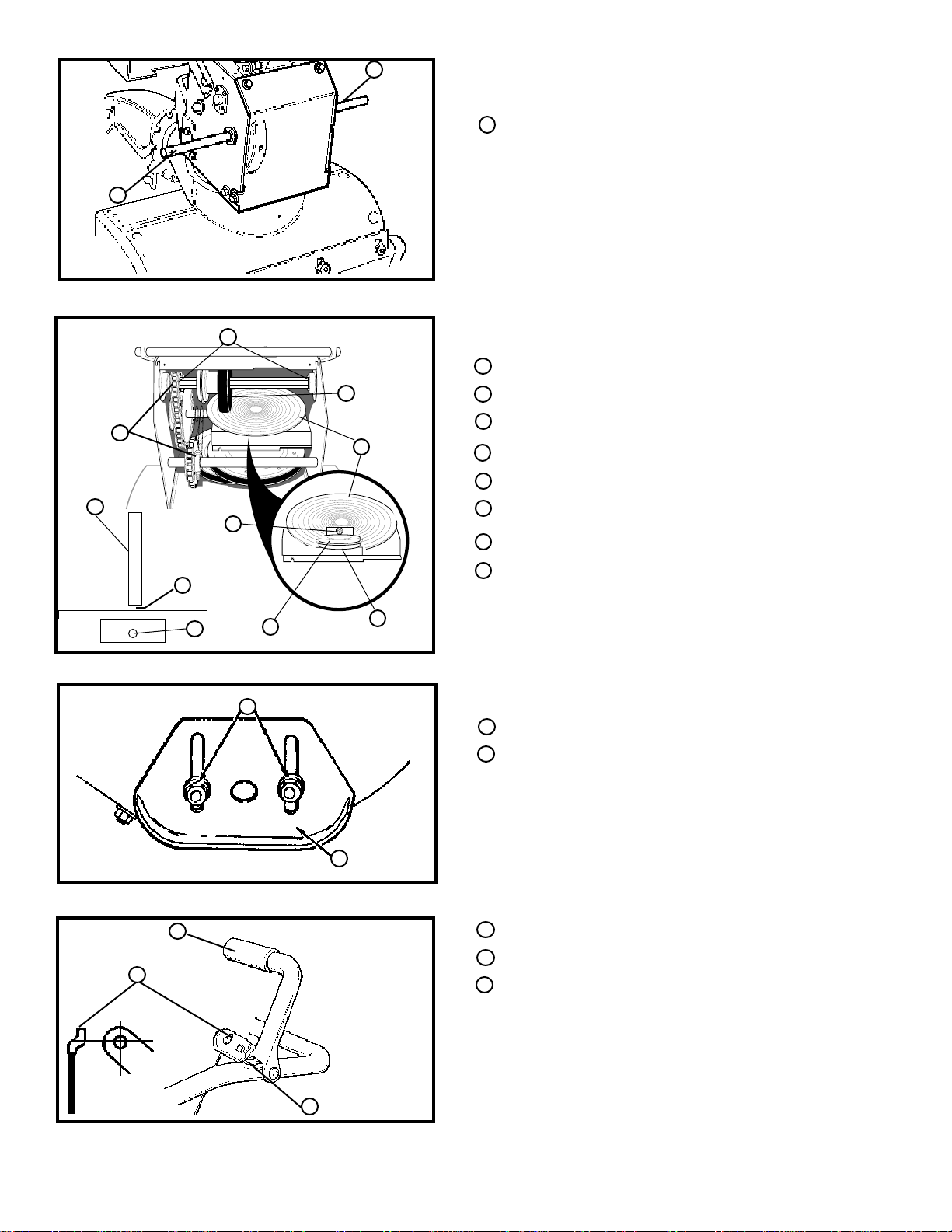
TO REPLACE AUGER SHEAR BOLT
The augers are secured to the auger shaft with special
bolts (See III.32) that are designed to break (to protect
the machine) if an object becomes lodged in the auger
housing. Use of a harder bolt will destroy the protection
provided by the shear bolt.
IMPORTANT: TO INSURE SAFETY AND LEVELS,
ONLY ORIGINALEQUIPMENT
SHEAR BOLTS SHOULD BE USED.
WHEN REPLACING SHEAR BOLTS,
BE SURE TO REPLACE SHEAR BOLT
SPACERS.
To replace a broken shear bolt, proceed as follows:
● Move the throttle to STOP and turn off all controls.
● Disconnect the spark plug wire. Be sure all moving
parts have stopped.
● Lubricate the auger shaft zerk fitting (See the Main-
tenance section in this manual).
● Align the hole in the auger with the hole in the auger
shaft. Install the new shear bolt, shear bolt spacer,
and locknut provided in parts bag.
● Reconnect the spark plug wire.
26
Page 26

SERVICE AND ADJUSTMENTS
TO ADJUST CARBURETOR
The carburetor (See III.33) has been pre-set at the
factory and readjustment should not be necessary. However, if the carburetor does need to be adjusted, proceed
as follows:
● Close the high speed adjusting screw by hand.
● Do not over tighten.
● Then open it 1-1/4 to 1-1/2 turns.
● Close the idle adjusting screw by turning clockwise
by hand. Do not over tighten.
● Then open it 1-1/4 to 1-1/2 turns.
● Start the engine and let it warm up.
● Set the throttle control to RUN. Adjust the high speed
adjusting screw in until the engine speed or sound
alters. Adjust the screw out until the engine speed
sound alters. Note the difference between the two
limits and set the screw in the middle of the range.
● Let the engine run undisturbed for 30 seconds after
each setting to allow the engine to react to the
previous adjustment.
● Set the throttle control to SLOW. Adjust the idle
adjusting screw in until the engine speed drops, then
adjust the screw out until the engine speed drops.
Note the difference between the two limits and set
the screw in the middle of the range.
● If the engine tends to stall under load or does not
accelerate from low speed to high speed properly,
adjust the high speed screw out in 1/8 turn increments until the problem is resolved. Let the engine
run for 30 seconds between settings.
TO ADJUST OR REPLACE THE SPARK
PLUG
If you have difficulty starting your snow thrower, you may
need to adjust or replace the spark plug. Follow the
instructions below.
Replace the spark plug if the electrodes are pitted or
burned or if the porcelain is cracked.
TO ADJUST:
● Clean the spark plug by carefully scraping the
electrodes (do not sand blast or use a wire brush).
● Be sure the spark plug is clean and free of foreign
material. Check the electrodes gap (See III.34) with
a wire feeler gauge and reset the gap to .030 inch if
necessary.
TO REPLACE:
● Remove the spark plug wire.
● Clean the area around the plug base to prevent dirt
from entering the engine when the plug is removed.
● Remove the spark plug. If it is cracked, fouled or
dirty, it must be replaced.
● Set the gap between the electrodes of the new spark
plug at .030 inch. Next, install the spark plug in the
cylinder head. Tighten the plug to 18 to 23 foot
pounds. If you do not use a torque wrench, tighten
the plug firmly (See III.34).
IMPORTANT: NEVER TAMPER WITH THE ENGINE
GOVERNOR, WHICH IS FACTORY
SET FORPROPER ENGINE SPEED.
OVER-SPEEDING THE ENGINE
ABOVE THE FACTORY HIGH SPEED
SETTING CAN BE DANGEROUS. IF
YOU THINK THE ENGINE -GOVERNED HIGH SPEED NEEDS ADJUSTING, CONTACT YOUR NEAREST AUTHORIZED SERVICE CENTER, WHICH HAS THE PROPER
EQUIPMENT AND EXPERIENCE TO
MAKE ANY
NECESSARY ADJUSTMENTS. A
DISTRIBUTOR'S LIST IS ON THE
INSIDE BACK COVER OF THIS
MANUAL.
27
Page 27

STORAGE
CAUTION: NEVER STORE THE ENGINE
WITH FUEL IN THE TANK INDOORS OR
IN AN ENCLOSED, POORLY VENTILATED AREA WHERE FUEL FUMES MAY
REACH AN OPEN FLAME, SPARK OR
PILOT LIGHT AS ON A FURNACE, WATER HEATER, CLOTHES DRYER, ETC.
NOTE: Immediately prepare your snow thrower for stor-
age at the end of the season or if the unit will not be used
for 30 days or more.
SNOW THROWER
Thoroughly clean the snow thrower.
● Lubricate all lubrication points (See the Mainte-
nance section).
● Be sure that all nuts, bolts and screws are securely
fastened. Inspect all visible moving parts for damage, breakage and wear. Replace if necessary.
● Touch up all rusted or chipped paint surfaces; sand
lightly before painting.
● Cover the bare metal parts of the blower housing
auger and the impeller with rust preventative, such
as sprayable lubricant.
NOTE: A yearly checkup or tuneup by a authorized
Service Center is a good way to insure that your snow
thrower will provide maximum performance for the next
season.
ENGINE
IMPORTANT: EMPTYING THE FUEL SYSTEM BE-
FORE STORAGE IS IMPORTANT TO
PREVENT GUM DEPOSITS FROM
FORMING IN ESSENTIAL FUEL SYSTEM PARTS SUCH AS THE CARBURETOR, FUEL FILTER, FUEL HOSE
OR TANK DURING STORAGE. ALSO,
EXPERIENCE INDICATES THAT ALCOHOL BLENDED FUELS (CALLED
GASOHOL OR USING ETHANOL OR
METHANOL) CAN ATTRACT MOISTURE WHICH LEADS TO SEPARATION AND FORMATION OF ACIDS
DURING STORAGE. ACIDIC GAS CAN
DAMAGE THE FUEL SYSTEM OF AN
ENGINE WHILE IN STORAGE.
● Drain the gasoline from the fuel tank by removing the
fuel line. Drain the fuel and reinstall the fuel line.
● Start the engine and run at SLOW (idle) speed until
the engine stops from lack of fuel.
● Drain the carburetor by pressing upward on the bowl
drain (See III.33), located below the carburetor cover.
NOTE: Fuel stabilizer (such as STA-BIL) is an accept-
able alternative in minimizing the formation of fuel gum
deposits during storage. Add stabilizer to gasoline in the
fuel tank or storage container. Always follow the mix ratio
found on stabilizer container. Run the engine at least 10
minutes after adding stabilizer to allow the stabilizer to
reach the carburetor. Do not drain the gas tank and
carburetor if using fuel stabilizer.
● Remove the spark plug and squirt one (1) ounce of
engine oil into the cylinder. Pull the recoil starter rope
slowly, allowing the piston to coat the internal engine
parts. Install an old spark plug. This prevents fouling
a new plug with the preservative used to lubricate the
internal parts of the engine. Close the choke and
plug the muffler opening.
OTHER
● If possible, store your snow thrower indoors and
cover it to give protection from dust and dirt.
● If the machine must be stored outdoors, block up the
snow thrower to be sure the entire machine is off the
ground.
● Cover the snow thrower with a suitable protective
cover that does not retain moisture. Do not use
plastic.
IMPORTANT: NEVER COVER SNOW THROWER
WHILE ENGINE AND EXHAUST
AREAS ARE STILL WARM.
CAUTION: DRAIN FUEL INTO APPROVED
CONTAINER OUTDOORS, AWAY FROM
OPEN FLAME.
28
Page 28

TROUBLESHOOTING POINTS
TROUBLE CAUSE CORRECTION
Difficult starting
Engine runs erratic
Engine stalls
Engine runs erratic;
Loss of power
Excessive vibration
Unit fails to propel
itself
Defective spark plug.
Water or dirt in fuel system.
Blocked fuel line or empty gas
tank or stale gasoline.
Unit running on CHOKE.
Water or dirt in fuel system.
Carburetor out of adjustment.
Loose parts; damaged impeller.
Drive belt loose or damaged.
Incorrect adjustment of traction
drive cable.
Replace defective plug.
Use carburetor bowl drain to flush and refill with fresh fuel.
Clean fuel line; check fuel supply; add fresh
gasoline.
Set choke lever to RUN position.
Use carburetor bowl drain to flush and refill with fresh fuel.
Adjust carburetor.
Stop engine immediately and disconnect spark plug wire.
Tighten all bolts and make all necessary repairs. If vibration
continues, have the unit serviced by a competent repairman.
Replace drive belt.
Adjust traction drive cable.
Unit fails to discharge
snow
Worn or damaged friction wheel.
Auger drive belt loose or
damaged.
Auger control cable not adjusted
correctly.
Shear bolt broken.
Discharge chute clogged.
Foreign object lodged in auger.
Replace friction wheel.
Adjust auger drive belt; replace if damaged.
Adjust auger control cable.
Replace shear bolt.
Stop engine immediately and disconnect spark plug wire.
Clean discharge chute and inside of auger housing.
Stop engine immediately and disconnect spark plug wire.
Remove object from auger.
29
Page 29

24" SNOW THROWER MODEL ST 724
ENGINE REPAIR PARTS
10
12
13
41
43
44
51
31
53
54
53
57
REF. AUGER
FRAME
33
54
34
59
59
59
REF.
PULLEY
REF.
NO PART NO. PART NAME
10 ENGINE 7HP TEC (SEE ENGINE MANUAL) 12 601 00 00-73 SCREW, 5/16-18 X .75 13 601 00 00-23 WASHER, HVSPTLK .328X.60X.09 31 601 00 14-32 GUIDE, ROD BELT RH 33 601 00 00-23 WASHER, HVSPTLK .328X.60X.09 34 601 00 14-33 SCREW 5/16-24X.625 41 601 00 14-32 GUIDE, ROD BELT LH 43 601 00 00-23 WASHER, HVSPTLK .328X.60X.09 44 601 00 14-33 SCREW 5/16-24X.625 51 601 00 14-34 WASHER, CRANKSHAFT 53 601 00 14-36 PULLEY, HALF V3L 2.00X.752ID 54 601 00 14-35 FLATWASHER, .752X.91X.02 57 601 00 14-37 BELT, V 3L 33.13LG 59 601 00 14-38 FLATWASHER, .765X1.12X.06 60 601 00 15-93 PULLEY, ENGINE V 4L 63 601 00 17-37 BELT, V 4L 36.6LG 67 601 00 14-41 FLATWASHER 68 601 00 00-15 WASHER, REGSPTLK .393X.60X.10 69 601 00 05-27 SCREW 3/8-24 X 1.00 NYL
601 00 17-36 OWNER'S MANUAL ENG/FR
60
63
67
68
69
REF.
PULLEY
30
319042E
Page 30

24" SNOW THROWER MODEL ST 724
FRAME REPAIR PARTS
107
108
117
118
105
106
104
HOUSING
119
85
116
WELDED TO
80
91
86
90
161
88
162
144
91
143
146
133
142
102
REF.
ENGINE
141
101
148
149
140
145
112
100
132
115
131
130
103
160
REF. KEY# 133
129
107
110
120
121
122
127
125
128
126
REF.
IMPELLER
HOUSING
REF.
NO PART NO. PART NAME
80 601 00 17-38 FRAME, ASSY ENG. MT.
85 601 00 14-43 SCREW 5/16-24X1.00
86 601 00 08-23 NUT, 5/16-24 HEXWD FLLK
88 601 00 05-19 SCREW, 5/16-18X.50 WAHHTAP
90 601 00 17-39 COVER, BOTTOM WHEEL DRIVE
91 601 00 14-45 SCREW 1/4-20 X .63 WAHHTAP
100 601 00 10-89 IDLER SPRING
101 601 00 14-46 FLATWASHER, .53X1.00X.063
102 601 00 14-47 BEARING FLANGE
103 601 00 15-97 ASSY, SHAFT AUG CLUTCH
104 601 00 14-49 LEVER, ASSY AUGER CLUTCH
105 601 00 14-51 SPRING PIN .165DIAX.88LG
106 601 00 14-47 BEARING, FLANGE
107 601 00 14-52 NUT, 1/2 PUSH ON
108 601 00 14-53 CABLE, .205 EYE 6.125LG
110 601 00 15-98 BOLT, 3/8-16X1.25 CARR.
111 601 00 00-20 FLATWASHER .406X.81X.065
112 601 00 14-54 PULLEY, IDLER
115 601 00 13-35 NUT, 3/8-16 HEXCTRLKJAM
116 601 00 14-55 SPOOL, CABLE AUGER CLUTCH
117 601 00 14-56 SCREW 1/4-20X1.75
118 601 00 00-18 FLATWASHER .281X.63X.065
119 601 00 00-62 NUT 1/4-20 REGHEXCTRLK
120 601 00 14-46 FLATWASHER .53X1.00X.063
REF.
NO PART NO. PART NAME
121 601 00 15-99 BEARING SLEV .520IDX.70ODX.65
122 601 00 14-52 NUT 1/2 PUSH ON
125 601 00 16-05 BRACKET, BRAKE ARM
126 601 00 16-02 BOLT, BRAKE ARM 9/16-18
127 601 00 16-01 NUT 9/16-18 JAM CTRLK
128 601 00 16-04 BOLT-BRAKE ARM ADJ
129 601 00 14-73 FLATWASHER .505X1.00X.06
130 601 00 16-03 NUT 1/2-20 JAM CTRLK
131 601 00 14-59 PAD, AUGER/IMPELLER BRAKE
132 601 00 14-51 PIN, SPRING .165DIAX.88LG
133 601 00 14-60 SPRING, TENSION RETURN
140 601 00 14-61 LEVER, IDLER ARM TRACTION
141 601 00 00-73 SCREW 5/16-18X.75
142 601 00 14-62 FLATWASHER .328X1.25X.075
143 601 00 14-63 BUSHING, IDLER LEVER
144 601 00 14-64 NUT, 5/16-18 HEXNYL
145 601 00 10-89 IDLER SPRING
146 601 00 17-40 SCREW 3/8-16X1.25
148 601 00 14-54 PULLEY, IDLER
149 601 00 13-35 NUT, 3/8-16 HEXCTRLKJAM
160 601 00 14-65 COVER, BELT
161 601 00 14-45 SCREW 1/4-20X.63 WAHHTAP
162 601 00 00-18 FLATWASHER .281X.63X.065
334338B
31
Page 31

24" SNOW THROWER MODEL ST 724
DRIVE COMPONENT REPAIR PARTS
192
191
211
190
198
195
210
215
221
217
231
216
247
222
232
196
223
193
271
244
248
249
246
245
257
244
250
256
277
223
REF.
AUGER FRAME
226
255
224
225
227
228
229
235
240
230
REF.
NO PART NO. PART NAME
190 601 00 14-66 LEVER, ASSY TRACTION CLUTCH
191 601 00 14-47 BEARING, FLANGED
192 601 00 09-30 COTTER PIN .125 DIAX1.00LG
193 601 00 14-67 SPRING, RETURN
195 601 00 14-68 LEVER, SPRING TRAC CLUTCH
196 601 00 13-74 SCREW, 1/4-20X.63
198 601 00 00-62 NUT, 1/4-20 REGHEXCTRLK
210 601 00 14-69 DISC, ASSY FRICTION WHEEL
211 601 00 14-70 ZERK, GREASE
215 601 00 14-71 SHAFT, HEX TRACTION
216 601 00 14-72 BEARING, TRUNION
217 601 00 14-73 FLATWASHER, .680X1.12X.060
221 601 00 14-74 RING, RETEX 1.16X.05TRU
222 601 00 14-75 FLATWASHER, .680X1.12X.060
223 601 00 05-65 BEARING, BALL 6203-2AA-C3
224 601 00 14-76 KEY, SQUARE .18SQX,63LG
225 601 00 14-77 PULLEY, V3L 6.50X.56
226 601 00 14-78 WASHER, WAVE .675X1.00X.020
227 601 00 00-03 FLATWASHER, .281X1.00X.063
228 601 00 00-14 WASHER, RSPTLK .263X.49X.07
229 601 00 00-68 SCREW 1/4-20X.75
276
278
270
275
REF.
NO PART NO. PART NAME
230 601 00 14-79 BEARING & RETAINER ASSY
231 601 00 05-19 SCREW 5/16-18X.50 WAHHTAP
232 601 00 00-23 WASHER, HVSPTLK .328X.60X.09
235 601 00 14-80 WASHER, SP .502X.75X.0605
240 601 00 14-81 SHAFT & SPROCKET ASSY
244 601 00 14-73 FLATWASHER .505X1.00X.06
245 601 00 17-41 BEARING, TRUNION CLUTCH
246 601 00 14-83 WHEEL, ASSY FRICTION DISC
247 601 00 13-74 SCREW, 1/4-20X.63
248 601 00 00-14 WASHER, RGSPTLK .263X.49X.07
249 601 00 00-11 NUT, 1/4-20 REGHEX
250 601 00 14-80 WASHER, SP .502X.75X.0605
255 601 00 14-79 BEARING & RETAINER ASSY
256 601 00 05-19 SCREW 5/16-18X.50 WAHHTAP
257 601 00 00-23 WASHER, HVSPTLK .328X.60X.09
270 601 00 14-79 BEARING & RETAINER ASSY
271 601 00 05-19 SCREW 5/16-18X.50 WAHHTAP
275 601 00 14-85 JACK, ASY #41-36T&8T W/PBRG
276 601 00 14-79 BEARING & RETAINER ASSY
277 601 00 05-19 SCREW 5/16-18X.50 WAHHTAP
278 601 00 14-86 CHAIN ROLLER #42 X 40P
313995F
32
Page 32

24" SNOW THROWER MODEL ST 724
GEAR BOX REPAIR PARTS
340
320
321
322
324
323
312
304
301
310
306
305
303
310
316
311
313
311
326
327
315
312
314
300
REF.
NO PART NO. PART NAME
300 601 00 14-87 CASE, GEAR RH
301 601 00 14-88 CASE, GEAR LH
303 601 00 14-43 SCREW 5/16-24X1.00
304 601 00 08-23 NUT, 5/16-24 HEXWDFLLK
305 601 00 16-07 SCREW, 5/16-24X1.50
306 601 00 14-90 PIPE PLUG
310 601 00 14-91 SEAL, OIL
311 601 00 14-92 BEARING, SLEEVE
312 601 00 14-93 FLATWASHER
313 601 00 14-94 SHAFT, AUGER OUTPUT 22"
314 601 00 14-95 GASKET, GEAR BOX
315 601 00 14-96 WORM GEAR
316 601 00 14-97 KEY, WOODRUFF #91
320 601 00 14-98 RING, QUAD
321 601 00 14-99 BEARING, FLANGE
322 601 00 15-00 FLATWASHER .752X1.24X.093
323 601 00 15-01 BEARING, ROLL
324 601 00 15-00 FLATWASHER .752X1.24X.093
326 601 00 15-02 KEY, HI-PRO 606
327 601 00 15-03 WORM GEAR
330 601 00 15-04 BRING, SLEV .752IDX.88ODX.755
340 601 00 15-05 IMPELLER, ASSY
330
314014C
33
Page 33

24" SNOW THROWER MODEL ST 724
AUGER HOUSING REPAIR PARTS
480
483
484
482
506
505
485
508
501
499
497
490
504
536
491
511
506
532
522
493
523
500
REF.
IMPELLER
BOLT PATTERN ON FRAME BRACKETS
ARE EXCLUSIVE TO 13" TIRE & TRAC
APPLICATIONS.
NOTE
520
530
544
542
527
543
531
540
525
541
533
526
512
534
535
513
521
524
510
514
REF.
NO PART NO. PART NAME
480 601 00 16-09 PULLEY, V4L 8.40
482 601 00 15-07 KEY, SQUARE .18SQX.88LG
483 601 00 14-46 FLATWASHER, .53X1.00X.063
484 601 00 01-07 NUT, 1/2-20 REGHXCTRLK
485 601 00 16-10 SPACER, SLEV .676X1.00X.53
490 601 00 15-09 RETAINER, BALL
491 601 00 05-65 BRING, BALL 6203-2AA-C3
493 601 00 00-73 SCREW 5/16-18X.75
497 601 00 00-23 WASHER, HVSPTLK .328X.60X.09
499 601 00 00-12 NUT, 5/16-18 REGHEX
500 601 00 15-10 HOUSING, ASSY 24/12
501 601 00 16-12 BRACKET & NUTS ASSY
504 601 00 15-12 SCREW 3/8-16X.75
505 601 00 00-15 WASHER, RGSPTLK .393X.68X.10
506 601 00 00-60 NUT 3/8-16 REGHEXCTRLK
508 601 00 17-42 STUD, BRAKE ARM
510 601 00 17-43 BLADE, SCRAPER 24"
511 601 00 14-11 BOLT, 5/16-18X.75 CARR.
512 601 00 00-19 FLATWASHER .344X.69X.065
513 601 00 17-44 WASHER, SPTLK .31X.58X.08
514 601 00 00-12 NUT, 5/16-18 REGHEX
REF.
NO PART NO. PART NAME
520 601 00 18-69 AUGER, ASSY LH 22"
521 601 00 18-70 AUGER, ASSY RH 22"
522 601 00 14-56 SCREW 1/4-20X1.75
523 601 00 15-17 SPACER, SLEV .250X.47X.20
524 601 00 00-62 NUT 1/4-20 REGHEXCTRLK
525 601 00 15-18 AUGER SHAFT BEARING
526 601 00 15-19 FLATWASHER 1.005X1.31X.035
527 601 00 05-20 SCREW, 5/16-18X.75 WAHHTAP
530 601 00 15-21 PLATE, AUGER HSNG RH
531 601 00 15-20 PLATE, AUGER HSNG LH
532 601 00 14-11 BOLT 5/16-18X.75 CARR.
533 601 00 00-19 FLATWASHER .344X.69X.065
534 601 00 00-23 WASHER, HVSPTLK .328X.60X.09
535 601 00 00-12 NUT, 5/16-18 REGHEX
536 601 00 08-99 BOLT, 5/16-18X1.00 CARR.
540 601 00 17-45 SKID, HEIGHT ADJUST
541 601 00 14-11 BOLT, 5/16-18X.75 CARR.
542 601 00 00-19 FLATWASHER .344X.69X.065
543 601 00 00-23 WASHER, HVSPTLK .31X.58X.08
544 601 00 00-12 NUT, 5/16-18 REGHEX
34
334396C
Page 34

REF.
AUGER HOUSING
587
586
580
586
582
590
591
585
600
593
602
603
598
610
594
584
593
595
596
597
606
609
608
611
601
608
607
24" SNOW THROWER MODEL ST 724
DISCHARGE CHUTE REPAIR PARTS
REF.
NO PART NO. PART NAME
580 601 00 18-36 CHUTE, UPPER
582 601 00 13-91 SCREW, 5/16-18X.75 SLTRMA
584 601 00 14-64 NUT, 5/16-18 HEXNYL
585 601 00 13-91 SCREW, 5/16-18X.75
586 601 00 15-24 WASHER, PLASTIC .315X.75X.064
587 601 00 14-64 NUT, 5/16-18 HEXNYL
590 601 00 08-99 BOLT, 5/16-18X1.00 CARR.
591 601 00 06-54 FLATWASHER .469X.92X.066
593 601 00 15-24 WASHER, PLASTIC .315X.75X.064
594 601 00 00-19 FLATWASHER .344X.69X.065
595 601 00 00-23 WASHER, HVSPTLK .328X.60X.09
596 601 00 00-19 FLATWASHER .344X.69X.065
597 601 00 06-84 KNOB, T 2 BLADE W/5/16-18 NUT
REF.
NO PART NO. PART NAME
598 601 00 00-12 NUT 5/16-18 REGHEX
600 601 00 18-37 CHUTE, LOWER
601 601 00 08-99 BOLT 5/16-18X1.00 CARR.
602 601 00 00-19 FLATWASHER .344X.69X.065
603 601 00 14-64 NUT 5/16-18 HEXNYL
606 601 00 18-38 COLLAR, CHUTE RECT.
607 601 00 00-68 SCREW 1/4-20X.75
608 601 00 00-18 FLATWASHER, .281X.63X.065
609 601 00 00-62 NUT, 1/4-20 REGHEXCTRLK
610 601 00 18-39 RETAINER, RING INNER
611 601 00 18-40 RETAINER, RING OUTER
337310B
35
Page 35

24" SNOW THROWER MODEL ST 724
WHEEL ASSEMBLY REPAIR PARTS
679
REF.
RIGHT WHEEL
677
676
671
655
675
652
653
654
650
REF.
LEFT WHEEL
675
671
655
656
678
673
678
REF.
NO PART NO. PART NAME
650 601 00 15-33 SHAFT, AXLE WHEEL/MID
652 601 00 15-34 SPROCKET & HUB ASSY
653 601 00 15-35 SCREW 1/4-20X2.25
654 601 00 00-62 NUT, 1/4-20 REGHEXCTRLK
655 601 00 15-36 BEARING, FLANGE
656 601 00 14-86 CHAIN, ROLLER #42 X 40P
671 601 00 14-38 FLATWASHER .765X1.12X.06
673 601 00 17-46 BUSHING, WHEEL 4"LG
675 601 00 17-47 TIRE & RIM 13X5.0X6
676 601 00 15-39 SCREW, SHR 1/4-20X1.75
677 601 00 00-62 NUT 1/4-20 REGHEXCTRLK
678 601 00 15-40 RING, RETAINING
679 601 00 15-41 PIN, KLIK
318542E
36
Page 36

24" SNOW THROWER MODEL ST 724
HANDLES REPAIR PARTS
731
729
730
733
741
739
721
724
744
732
745
733
ASSEMBLY
RIGHT SIDE
725
920
921
726
754
727
728
922
921
720
ASSEMBLY
LEFT SIDE
750
923
743
753
752
751
REF. BLOWER
FRAME
REF.
NO PART NO. PART NAME
720 601 00 15-42 UPPER HANDLE LH
721 601 00 15-43 UPPER HANDLE RH
724 601 00 15-44 SCREW, 3/8-16X3.00
725 601 00 00-20 FLATWASHER .406X.81X.065
726 601 00 00-15 WASHER, RGSPTLK .393X.68X.10
727 601 00 00-60 NUT, 3/8-16 REGHEXTRLK
728 601 00 15-45 STOP, PLASTIC .375
729 601 00 15-46 GRIP, HANDLE
730 601 00 15-47 HANDLE, CLUTCH RH
731 601 00 15-48 HANDLE, CLUTCH LH
732 601 00 15-49 PIN, PIVOT
738 601 00 05-16 PUSH ON CAP
739 601 00 15-50 BUMPER, RECT
752
REF.
NO PART NO. PART NAME
741 601 00 15-51 CABLE, CLUTCH
743 601 00 15-52 SPRING, TENSION
744 601 00 15-53 SPRING, AUGER CLUTCH
745 601 00 00-62 NUT, 1/4-20 REGHEXCTRLK
750 601 00 15-54 HANDLE, LOWER
751 601 00 00-73 SCREW, 5/16-18X.75
752 601 00 00-23 WASHER, HVSPTLK .328X.60X.09
753 601 00 00-12 NUT 5/16-18 REGHEX
754 601 00 05-20 SCREW, 5/16-18X.75 WAHHTAP
920 601 00 15-55 SCREW, 3/8-16X2.00
921 601 00 00-20 FLATWASHER .406X.81X.065
922 601 00 00-15 WASHER RGSPTLK .393X.60X.10
923 601 00 00-60 NUT, 3/8-16 REGHEXCTRLK
319050H
37
Page 37

24" SNOW THROWER MODEL ST 724
CONTROL PANEL REPAIR PARTS
920
REF.
UPPER HANDLE
762
761
762
774
762
773
789
921
763
772
760
777
766
764
771
790
776
770
REF.
NO PART NO. PART NAME
760 601 00 15-56 PANEL, CONTROL W/LIGHT
761 601 00 15-57 SCREW, 5/16-18X1.75
762 601 00 00-19 FLATWASHER .344X.69X.065
763 601 00 00-23 WASHER HVSPTLK .328X.60X.09
764 601 00 00-12 NUT, 5/16-18 REGHEX
766 601 00 15-58 PLATE, PANEL
770 601 00 15-59 HANDLE ASSY SPEED CONTROL
771 601 00 15-55 SCREW 3/8-16X2.00
772 601 00 15-60 SPRING
773 601 00 00-20 FLATWASHER .406X.81X.065
774 601 00 06-53 NUT, 3/8-16 HEXNYL
776 601 00 17-48 BRACKET, SPEED CONTROL
777 601 00 05-20 SCREW, 5/16-18X.75 WAHHTAP
780 601 00 00-25 PIN, COTTER .090DIAX.75LG
781 601 00 00-19 FLATWASHER, .344X.69X.065
784 601 00 15-62 ROD, SPEED CONTROL
788 601 00 15-63 NUT, TRUNNION 5/16-24
789 601 00 00-19 FLATWASHER .344X.69X.065
790 601 00 00-25 COTTER PIN .090DIAX.73LG
811 601 00 15-64 BEARING, FLANGED
812 601 00 15-65 ROD, ASSY YOKE "PANEL"
813 601 00 00-60 NUT 3/8-16 REGHEXCTRLK
920 601 00 02-36 HANDLE, 3/8-16 MOLDED
921 601 00 00-60 NUT, 3/8-16 REGHEXCTRLK
788
812
811
784
789
790
813
319052F
38
Page 38

24" SNOW THROWER MODEL ST 724
DECALS
VIEW FROM
REAR TANK
825
831
838
834
833
832
835
822
VIEW FROM REAR
830
824
826
REF.
NO PART NO. PART NAME
822 601 00 15-75 DECAL, OVER ADJ OF DISC
824 601 00 15-76 DECAL, DANGER FOOT SYM
825 601 00 15-77 DECAL, DUAL STAGE
826 601 00 18-41 DECAL, AUGER HOUSING TOP
830 601 00 15-79 DECAL, DANGER FINGER
831 601 00 15-80 DECAL, FREE IMPELLER
832 601 00 15-81 DECAL, TRACT DR -CHUTE ROT
833 601 00 15-82 DECAL, SNOW CONDITIONS
834 601 00 15-83 DECAL, GEAR SELECT/AUGER
835 601 00 18-42 DECAL, HANDLE PANEL
838 601 00 15-85 DECAL, BELT STRETCH ADJ.
334544C
39
Page 39

24" SNOW THROWER MODEL ST 724
CHUTE CONTROL ROD REPAIR PARTS
856
855
854
855
850
860
866
867
REF.
LOWER HANDLE
864
863
863
861
873
874
875
872
871
870
REF.
NO PART NO. PART NAME
850 601 00 17-49 CRANK ASSY W/YOKE
854 601 00 15-69 KNOB, SLEEVE
855 601 00 00-20 FLATWASHER .406X.81X.065
856 601 00 12-91 NUT, PUSH ON 3/8"
860 601 00 17-50 EYE BOLT, 3/8-16X6.00
861 601 00 14-08 GROMMET, EYE BOLT
863 601 00 14-09 NUT, 3/8-16 HEXJAM
864 601 00 00-20 FLATWASHER .406X.81X.065
866 601 00 00-20 FLATWASHER, .406X.81X.065
867 601 00 06-53 NUT, 3/8-16 REGHEX
870 601 00 18-30 BRACKET, WORM MOUNTING
871 601 00 18-31 WORM GEAR CHUTE ROTATE
872 601 00 18-32 BLOCK, UNIV. PIVOT
873 601 00 18-33 PIN, CLEVIS
874 601 00 18-34 PIN, UNIV. JOINT
875 601 00 18-35 COTTER PIN .06X.50
336677A
40
Page 40

NOTES
41
 Loading...