


GB
Operator’s manual
Please read the operator’s manual carefully and make sure you understand the instructions before using the machine.
ES
DE
FR
Manual de instrucciones
Lea detenidamente el manual de instrucciones y asegúrese de entender su contenido antes de utilizar la máquina.
PP 325 E
Bedienungsanweisung
Lesen Sie die Bedienungsanweisung sorgfältig durch und machen Sie sich mit dem Inhalt vertraut, bevor Sie das Gerät benutzen.
Manuel d’utilisation
Lire attentivement et bien assimiler le manuel d’utilisation avant d’utiliser la machine.
GGGGBBBB EEEESSSS DDDDEEEE FFFFRR
RR
KEY TO SYMBOLS
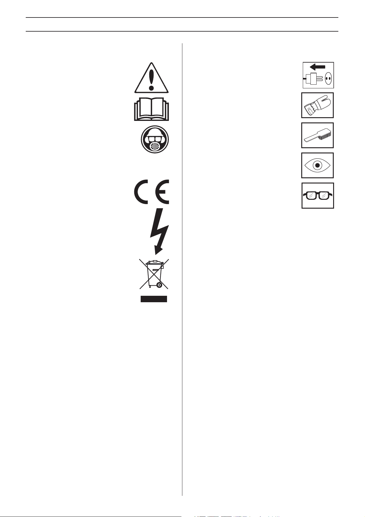
Symbols on the machine:
WARNING! The machine can be a
dangerous tool if used incorrectly or
carelessly, which can cause serious or
fatal injury to the operator or others.
Please read the operator’s manual
carefully and make sure you understand
the instructions before using the machine.
Always wear:
• Approved protective helmet
• Approved hearing protection
• Protective goggles or a visor
• Breathing mask
This product is in accordance with
applicable EC directives.
WARNING! High current.
Symbols in the operator’s manual:
Inspection and/or maintenance should be
carried out with the motor switched off and
the plug disconnected.
Always wear approved protective gloves.
Regular cleaning is required.
Visual check.
Protective goggles or a visor must be worn.
Environmental marking.
Symbols on the product or its packaging
indicate that this product cannot be handled
as domestic waste. It must instead be
submitted to an appropriate recycling station
for the recovery of electrical and electronic
equipment.
By ensuring that this product is taken care of correctly, you
can help to counteract the potential negative impact on the
environment and people that can otherwise result through the
incorrect waste management of this product.
For more detailed information about recycling this product,
contact your municipality, your domestic waste service or the
shop from where you purchased the product.
2 – English

CONTENTS
Contents
KEY TO SYMBOLS
Symbols on the machine: ............................................. 2
Symbols in the operator’s manual: ............................... 2
CONTENTS
Contents ...................................................................... 3
WHAT IS WHAT?
What is what on the hydraulic unit? ............................. 4
SAFETY INSTRUCTIONS
Steps before using a new hydraulic unit ..................... 5
Personal protective equipment ..................................... 5
Machine′s safety equipment ........................................ 6
General safety precautions .......................................... 6
General working instructions ....................................... 7
ASSEMBLING AND ADJUSTMENTS
Check the oil level ........................................................ 8
Check the air pressure in the tyres .............................. 8
Connect the hydraulic hoses. ....................................... 8
Connect the water cooling ........................................... 8
Connect a power source .............................................. 9
STARTING AND STOPPING
Before starting ............................................................. 10
Starting ........................................................................ 10
Stopping ....................................................................... 10
After work is completed ............................................... 10
MAINTENANCE
Service ......................................................................... 11
Maintenance ................................................................ 11
TECHNICAL DATA
PP 325 E ...................................................................... 13
EC-declaration of conformity ........................................ 14
English – 3
WHAT IS WHAT?
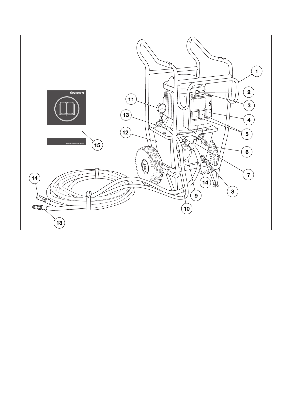
What is what on the hydraulic unit?
1 Frame for hydraulic hose
2 Switch
3 Emergency stop
4 Residual Current Circuit Breaker with Overcurrent
Protection (Only on 5-pin machines.)
5 Wall socket 2x230 V (Only on 5-pin machines.)
6 Connection for outgoing cooling water
7 Sight gauge
8 Connection for incoming cooling water
9 Hydraulic oil filter
10 Drain plug
11 Hydraulic pressure gauge
12 Hydraulic oil tank
13 Hydraulic hose, pressure OUT
14 Hydraulic hose, return IN
15 Operator′s manual
4 – English
SAFETY INSTRUCTIONS
Steps before using a new hydraulic unit
• Please read the operator’s manual carefully and make
sure you understand the instructions before using the
machine.
• This machine is primarily intended for WS 325, DM 406 H,
HS 170 and HH 170, but is also highly suitable as power
source for other equipment, e.g. Husqvarna ring saw.
• Read through the manual supplied with the hydraulic tool
before starting to use the machine.
• The machine can cause serious personal injury. Read the
safety instructions carefully. Learn how to use the
machine.
Always use common sense
It is not possible to cover every conceivable situation you can
face. Always exercise care and use your common sense.
Avoid all situations which you consider to be beyond your
capability. If you still feel uncertain about operating
procedures after reading these instructions, you should
consult an expert before continuing.
Do not hesitate to contact your dealer if you have any more
questions about the use of the machine. We will willingly be of
service and provide you with advice as well as help you to use
your machine both efficiently and safely.
Let your Husqvarna dealer regularly check the machine and
make essential adjustments and repairs.
All information and all data in the Operator’s Manual were
applicable at the time the Operator’s Manual was sent to print.
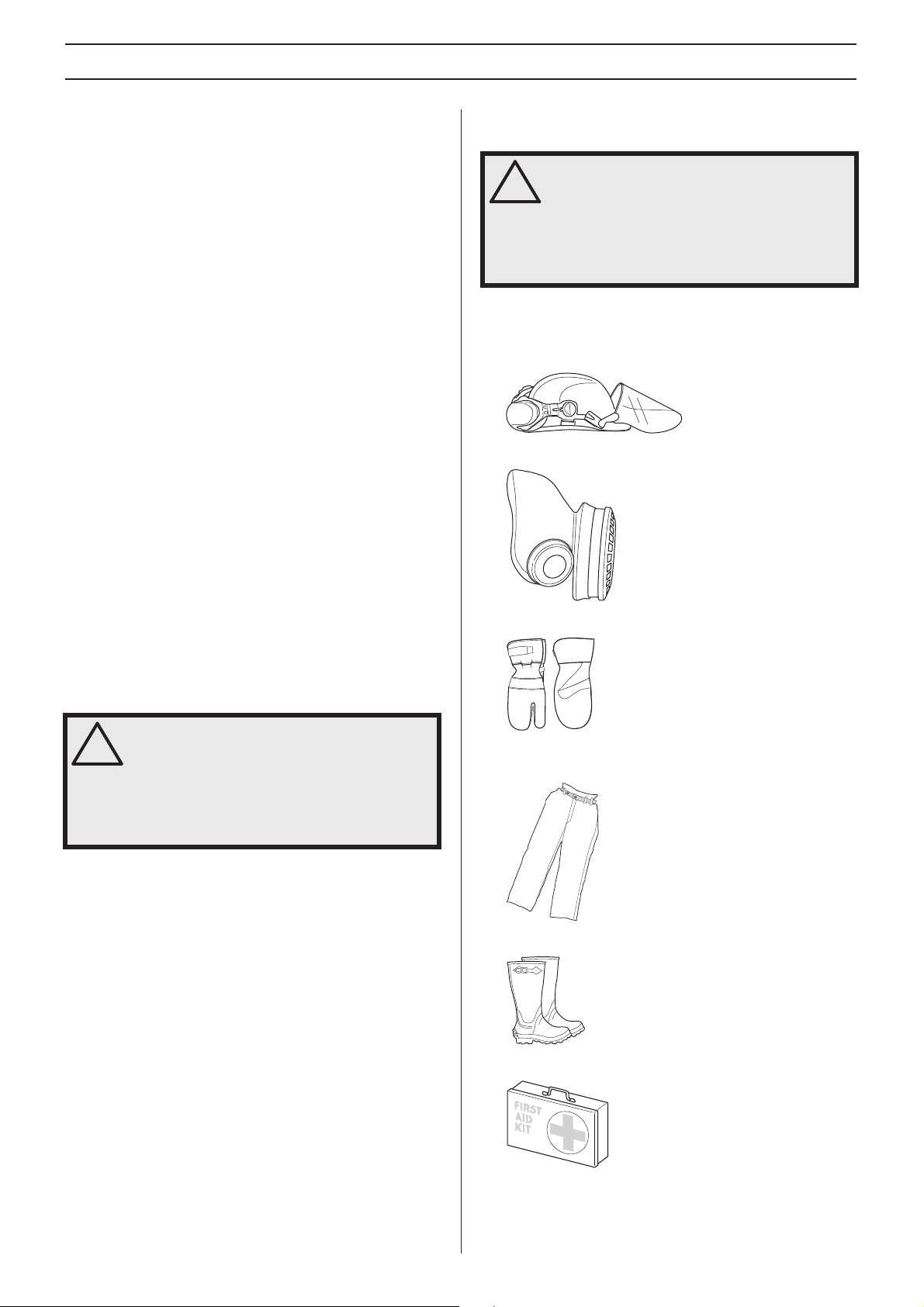
Personal protective equipment
WARNING! You must use approved personal
protective equipment whenever you use the
!
machine. Personal protective equipment
cannot eliminate the risk of injury but it will
reduce the degree of injury if an accident
does happen. Ask your dealer for help in
choosing the right equipment.
• Protective helmet
• Hearing protection
• Protective goggles or a visor
• Breathing mask
• Heavy-duty, firm grip gloves.
WARNING! Under no circumstances should
you modify the original design of the
!
machine without approval from the
manufacturer. Always use original spare
parts. Unauthorized modifications and/or
accessories may lead to serious injury or
death to the user or others.
• Tight-fitting, heavy-duty and comfortable clothing that
permits full freedom of movement.
• Boots with steel toe-caps and non-slip sole.
• Always have a first aid kit nearby.
English – 5

SAFETY INSTRUCTIONS
Machine′′′′s safety equipment
This section describes the machine′s safety equipment, its
purpose, and how checks and maintenance should be carried
out to ensure that it operates correctly. See the ”What is
what?” section to locate where this equipment is positioned
on your machine.
WARNING! Never use a machine that has
faulty safety equipment!
!
All servicing and repair work on the machine
requires special training. This is especially
true of the machine
your machine fails any of the checks
described below you must contact your
service agent. When you buy any of our
products we guarantee the availability of
professional repairs and service. If the
retailer who sells your machine is not a
servicing dealer, ask him for the address of
your nearest service agent.
Emergency stop
The emergency stop at the machine breaks the mains power
supply.
Testing the emergency stop
• Make sure that the hydraulic hoses are connected to each
other.
• Start the machine.
• Press the emergency stop and check that the engine
stops.
′′′′s safety equipment. If
• Check that the cord and extension cord are intact and in
good condition.
• Never use the machine if the cord is damaged, hand it in
to an authorized service workshop for repair.
• Do not use an extension cord while it is rolled up to avoid
overheating.
• The machine should be connected to an earthed outlet
socket.
• Check that the mains voltage corresponds with that stated
on the rating plate on the machine.
• Always switch off the power to the hydraulic unit and pull
out the electric cable before moving the equipment.
• Keep all parts in good working order and ensure that all
fixtures are properly tightened.
• Never use a machine that is faulty. Carry out the checks,
maintenance and service instructions described in this
manual. Some maintenance and service measures must
be carried out by trained and qualified specialists. See
instructions under the heading Maintenance.
• Do not modify safety equipment. Check regularly that they
function as they should. The machine must not be run with
defective or disassembled safety equipment.
• Never allow anyone else to use the machine without first
ensuring that they have understood the contents of the
operator’s manual.
• People and animals can distract you causing you to lose
control of the machine. For this reason, always remain
concentrated and focused on the task.
• Make sure no unauthorised persons are in the working
area, otherwise there is a risk of serious personal injury.
• Be careful as clothing, long hair, and jewellery can get
caught in moving parts.
• Observe care when lifting. You are handling heavy parts,
which implies the risk of pinch injuries or other injuries.
General safety precautions
Do not use the machine without first reading and
understanding the contents of this Operator’s Manual.
WARNING! There is always a risk of shocks
from electrically powered machines. Avoid
!
unfavourable weather conditions and body
contact with lightning conductors and metal
objects. Always follow the instructions in the
Operator’s manual to avoid damage.
• Never use the machine if you are tired, if you have drunk
alcohol, or if you are taking medication that could affect
your vision, your judgement or your co-ordination.
• Wear personal protective equipment. See instructions
under the heading ”Personal protective equipment”.
• Never pull out the plug by pulling the cord.
• Keep all cords and extension cords away from water, oil
and sharp edges. Make sure the cord is not pinched in
doors, fences or the like. Otherwise it can cause the object
to become live.
Transport and storage
• Always switch off the power to the hydraulic unit and pull
out the electric cable before moving the equipment.
• If there is a risk of freezing, the machine must be drained
of any remaining water coolant.
• The power unit is constructed as a wheeled cart with the
possibility of hanging hydraulic hoses for simple
transportation at the workplace.
• For transportation between workplaces, the power unit
should be stored in vertical position with the distribution
box facing upwards.
• Store the equipment in a lockable area so that it is out of
reach of children and unauthorized persons.
6 – English

SAFETY INSTRUCTIONS
General working instructions
WARNING! This section describes basic
safety directions for using the machine. This
!
information is never a substitute for
professional skills and experience. If you get
into a situation where you feel unsafe, stop
and seek expert advice. Contact your dealer,
service agent or an experienced user. Do not
attempt any task that you feel unsure of!
• All operators shall be trained in the use of the machine.
The owner is responsible for ensuring that the operators
receive training.
• Check that all couplings, connections and hydraulic hoses
are in full working order.
• Keep the hydraulic hoses and couplings free from dirt.
• Do not misuse hoses.
• Do not use hoses that are distorted, worn or damaged.
• Make sure that all hoses and electrical cables are
connected to the machine correctly before you start the
machine.
• Check that the hoses are connected correctly to the
machine and that the hydraulic couplings lock as intended
before pressurising the hydraulic system. The couplings
are locked by turning the outer sleeve on the female
coupling so that the slot moves away from the ball.
The pressure hoses in the system must always be
connected to the tool’s intake. The return hoses in the
system must always go to the tool’s outlet. Confusing the
connections can cause the tool to work in reverse, which
can result in personal injury.
• Never use the hydraulic hoses to lift the machine.
• Check the machine, couplings and hydraulic hoses daily
for leakage. A rupture or leak can cause a ”hydraulic fluid
injection” in the body or result in other serious physical
injury.
• Never disconnect the hydraulic hoses without first shutting
off and disconnecting the hydraulic unit and ensuring the
motors have stopped completely.
• If an emergency situation should arise anyway, push the
red emergency stop button on the power unit.
• Do not exceed the specified hydraulic fluid flow or
pressure for the tool being used. Excessive pressure or
flow can result in rupturing.
• Do not check for leakage with your hands. Contact with
the leak can result in serious personal injury caused by
the high pressure in the hydraulic system.
• Check the power supply and the power cables and make
sure that they are not damaged.
• Working close to power lines:
Hoses that are marked and approved as electrically non
conductive must be used when using hydraulic tools on or
in the vicinity of electrical cables. The use of other types
of hoses can result in serious physical injury or even
death.
When replacing hoses, hoses marked 'non-conducting
dielectric” must be used. The hoses must be regularly
checked for their electrical conductive insulation in
accordance with special instructions.
• Working close to gas conduits:
Always check and mark out where gas pipes are routed.
Cutting close to gas pipes always entails danger. Make
sure that sparks are not caused when cutting in view of
the risk of explosion. Remain concentrated and focused
on the task. Carelessness can result in serious personal
injury or death.
• Run the hydraulic system until it reaches its operation
temperature of 30
return pressure and other wear.
• Never leave the machine unsupervised with the motor
running.
• Always saw in a manner that permits easy access to the
emergency stop.
• Make sure that there is always another person close at
hand when you use the machines, so that you can call for
help if an accident should occur.
• People that need to be in close proximity of the machine
must wear hearing protection as the sound level when
cutting exceeds 85 dB(A).
• Do not use the machine in bad weather, such as dense
fog, rain, strong wind, intense cold, etc. Working in bad
weather is tiring and can lead to dangerous conditions,
e.g. slippery surfaces.
• Ensure that the working area is sufficiently illuminated to
create a safe working environment.
• Always ensure you have a safe and stable working
position.
• Observe care when lifting. You are handling heavy parts,
which implies the risk of pinch injuries or other injuries.
°C before starting to saw, to reduce
English – 7
ASSEMBLING AND ADJUSTMENTS
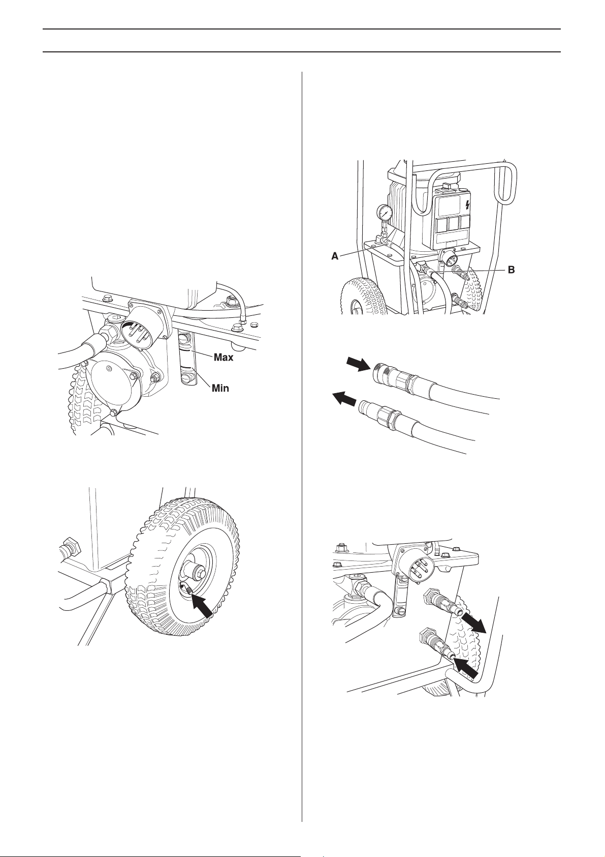
Check the oil level
The power pack is supplied with 12 litres of hydraulic oil 466
cSt HSH of a well-known brand. The oil is an environmentally
adapted and SP approved ester oil that will drastically reduce
the risk of allergic reaction or skin irritation upon contact. In
addition, the oil is quickly degradable in case of unintentional
release.
• Check the hydraulic fluid level in the power unit. This is
checked with the level indicator.
Min. level = red line
Max. level = black line
Do not exceed the max. level when filling the tank with
hydraulic fluid. The hydraulic fluid expands when it gets hot
and can overflow if the level is too high. Tank volume 12 l (3.2
US gallons).
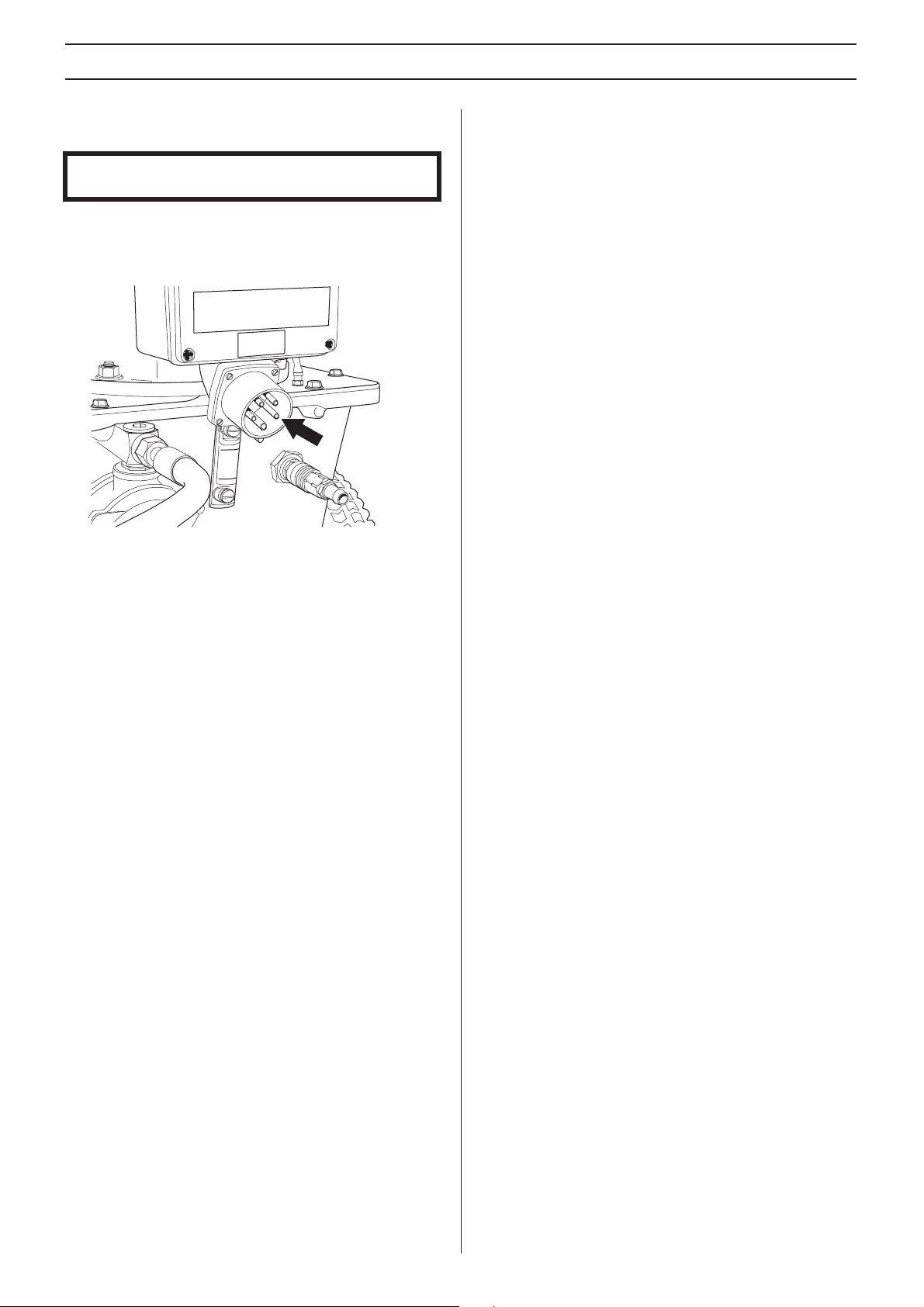
Connect the hydraulic hoses.
• The couplings should be wiped clean to reduce the risk of
leakage before the hoses are fitted.
• The couplings are locked by turning the outer sleeve on
the female coupling so that the slot moves away from the
ball.
Hydraulic hose, return IN (B)
Hydraulic hose, pressure OUT (A)
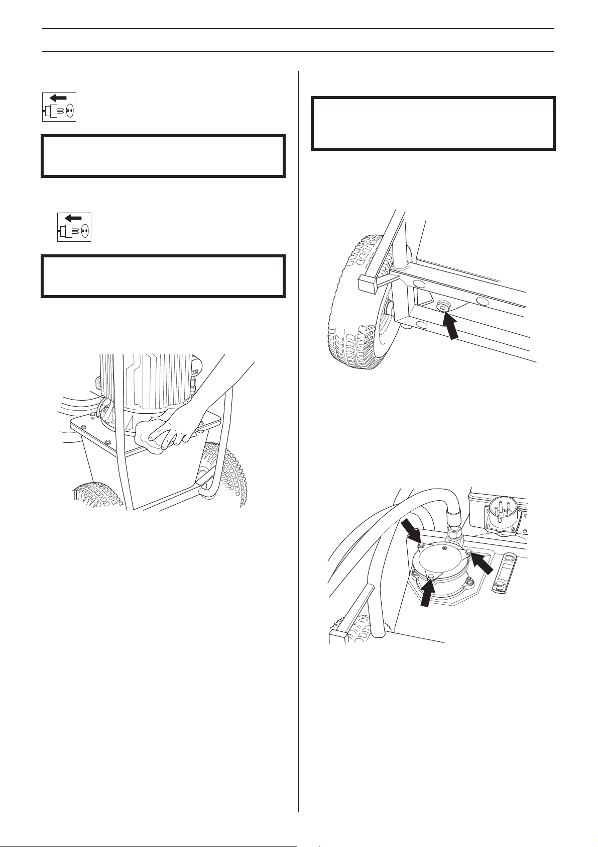
Check the air pressure in the tyres
• Check the air pressure in the tyres. This should be 2 bar.
Connect the water cooling
• Connect a water hose between the upper cooling
connection on the hydraulic oil tank and the working tool,
and also a hose from the closest hydrant via a tap to the
lower cooling connection on the tank.
• If no tool requiring water is used, just let the cooling water
flow to the closest floor drain.
8 – English
ASSEMBLING AND ADJUSTMENTS
Connect a power source
IMPORTANT! Check that the mains voltage corresponds
with that stated on the rating plate on the machine.
• Connect the incoming power cable. The cable must have
three phases and grounding. Neutral should also be
available as the single phase sockets on the distribution
box will not work otherwise. (Only on 5-pin machines.)
• The single phase sockets are protected with a 16 A
residual current circuit breaker with overcurrent protection
(C type). Following the connection on incoming current,
the single phase sockets can be used for e.g. a drilling
machine, water suction apparatus, etc.
English – 9
STARTING AND STOPPING
Before starting
Make sure that:
• The machine is correctly connected to a suitable power
supply and correctly fused.
• The hoses have been connected to a device.
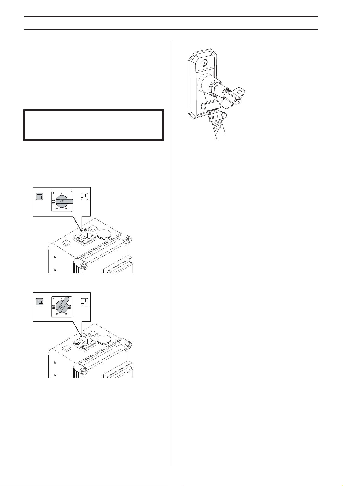
Starting
NOTICE! When starting, the switch must only be turned to
”START 5 SEC” for about 5 seconds. The switch is then
turned to "RUN". The engine may be damaged if the switch
is in the ”START 5 SEC" position too long or when operated.
The engine is started with a Y/D switch. The start takes place
in two steps to avoid overloading the fuse the machine is
connected to.
• Turn the switch to "START 5 SEC" in the direction
indicated by the lit lamp. The direction of rotation of the
engine will then be correct.
• Open the tap to suitable water flow for the tool in question.
If the tool does not require water, cooling water should still
flow through the radiator, and then to the closest floor
drain.
Stopping
Switch off by turning the switch to "0".
After work is completed
• Turn the switch to "RUN" when the engine speed is
constant after about 5 seconds.
• Disconnect the hydraulic hoses.
• If there is a risk of freezing, the machine must be drained
of any remaining water coolant. Disconnect incoming and
outgoing water hoses and tilt the machine forwards.
10 – English
MAINTENANCE
Service
IMPORTANT! All types of repairs may only be carried out by
authorised repairmen. This is so that the operators are not
exposed to great risks.
Maintenance
IMPORTANT! Inspection and/or maintenance should be
carried out with the motor switched off and the plug
disconnected.
Cleaning
Make sure to keep the connectors and pins clean. Clean with
a rag or brush.
Hydraulic oil
IMPORTANT! Changing liquids and filters must be done in
such a way that the machine’s hydraulic system and the
surrounding environment are not damaged. Dispose of
residual products according to local laws.
The hydraulic oil should be replaced when needed or once a
year.
• Place a collecting vessel under the tank’s drain plug and
open the plug.
NB! Do not use a high pressure washer to clean the power
unit. Do not wash the machine with water, as water can enter
the electrical system or the engine and cause damage to the
machine or short circuit.
• Screw on the drain plug when all the liquid has drained
out.
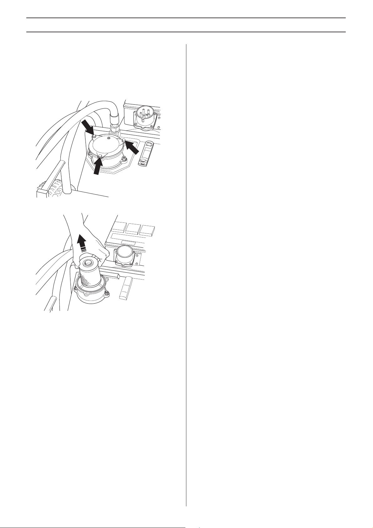
Hydraulic oil is refilled through the filter on the front of the
tank.
• Lay the power pack down with the filter housing facing
upwards.
• Remove the cover of the filter housing by removing the
three screws.
• Refill hydraulic oil through the filter element.
• Mount the filter housing cover.
• If also the oil filter is replaced, 12 l new hydraulic oil should
be filled.
English – 11
MAINTENANCE
Hydraulic oil filter
The filter should be replaced twice a year.
• Lay the power pack down with the filter housing facing
upwards.
• Remove the cover of the filter housing by removing the
three screws.
• Lift up the filter element.
• Push the new filter in place over the sleeve coupling in the
bottom of the filter housing.
• Mount the filter housing cover.
Tightening torque
When performing repair and maintenance work that include
demounting and subsequent mounting and tightening of
screws, the following torque should be used:
• M6: 10 Nm
• M8: 25 Nm
• M10: 50 Nm
Daily maintenance
Regularly check:
• The hydraulic fluid level in the hydraulic power unit, to
make sure it lies between the marks on the level glass.
• Check the tyre pressures.
• Any abnormal noises.
12 – English

TECHNICAL DATA
PP 325 E
Specified hydraulic output, kW/hp 9,3/12,6
Hydraulic oil flow, l/min / gpm 40/8,8
Hydraulic oil tank, l/gal 12/2,6
Cooling Water cooling
Size, (LxWxH), mm/inch 575x1040x780/22,6x40,9x30,7
Weight, kg/lbs 93/205
Max. working pressure, bar / psi 140/2031
Hose length (1/2" hose), mm/inch
Power supply
Check that the mains voltage corresponds with that stated on the rating plate on the machine.
200 V 50 Hz
200 V 60 Hz
230/400 V 50 Hz
230 V 60 Hz
400 V 50 Hz
440 V 50 Hz
575 V 60 Hz
8/315 (When hoses are extended beyond standard
length, 5/8" hose is recommended.)
Wall socket 2x230 V (Only on 5-pin machines.)
Noise emissions (see note 1)
Sound power level, measured dB(A) 94
Sound power level, guaranteed LWA dB(A) 99
Sound levels (see note 2)
Sound pressure level at the operators ear, dB(A) 83
Note 1: Noise emissions in the environment measured as sound power (LWA) in conformity with EC directive 2000/14/EC.
Note 2: Noise pressure level according to EN ISO 11201. Reported data for noise pressure level has a typical statistical dispersion
(standard deviation) of 1.0 dB(A).
13 – English

TECHNICAL DATA
EC-declaration of conformity
(Applies to Europe only)
Husqvarna AB, SE-433 81 Göteborg, Sweden, tel: +46-31-949000, declares under sole responsibility that the hydraulic unit
Husqvarna PP 325 E from 2010´s serial numbers and onwards (the year is clearly stated in plain text on the type plate with
subsequent serial number) is in conformity with the requirements of the COUNCIL’S DIRECTIVES:
• of May 17, 2006 "relating to machinery" 2006/42/EC
• of December 12, 2006 ”relating to electrical equipment” 2006/95/EC.
• of December 15, 2004 ”relating to electromagnetic compatibility” 2004/108/EC.
• of May 8, 2000 ”relating to the noise emissions in the environment” 2000/14/EC.
The following standards have been applied: EN ISO 12100:2003, EN 55014-1:2006, EN 55014-2/A1:2001, EN 61000-3-11:2000,
EN 982/A1:2008, EN 60204-1:2006.
Huskvarna December 29, 2009
Henric Andersson
Vice President, Head of Power Cutters and Construction Equipment
Husqvarna AB
(Authorized representative for Husqvarna AB and responsible for technical documentation.)
14 – English
ACLARACIÓN DE LOS SÍMBOLOS
Símbolos en la máquina:
¡ATENCIÓN! La máquina, si se utiliza de
forma errónea o descuidada, puede ser
una herramienta peligrosa que puede
causar daños graves e incluso la muerte al
usuario y a otras personas.
Lea detenidamente el manual de
instrucciones y asegúrese de entender su
contenido antes de utilizar la máquina.
Utilice siempre:
• Casco protector homologado
• Protectores auriculares homologados
• Gafas protectoras o visor
• Máscara respiratoria
Este producto cumple con la directiva CE
vigente.
¡ATENCIÓN! Corriente intensa.
Símbolos en el manual de instrucciones:
El control y/o mantenimiento de la máquina
debe hacerse con el motor parado y el
enchufe desenchufado.
Utilice siempre guantes protectores
homologados.
La máquina debe limpiarse regularmente.
Control visual.
Debe utilizarse gafas protectoras o visor.
Etiquetado ecológico.
El símbolo en el producto o en su envase
indica que no se puede tratar este producto
como desperdicio doméstico. Deberá por lo
tanto depositarse en un centro de recogida
adecuado para el reciclado de equipos
eléctricos y electrónicos.
Haciendo que este producto sea manipulado
adecuadamente, se ayuda a evitar consecuencias negativas
potenciales para el medio ambiente y las personas, lo que
puede ocurrir con la manipulación inadecuada como residuos
del producto.
Para obtener información más detallada sobre el reciclado de
este producto, contacte con la oficina municipal local, con el
servicio de eliminación de desperdicios domésticos o con la
tienda donde compró el producto.
Spanish – 15

ÍNDICE
Índice
ACLARACIÓN DE LOS SÍMBOLOS
Símbolos en la máquina: ............................................. 15
Símbolos en el manual de instrucciones: .................... 15
ÍNDICE
Índice ........................................................................... 16
¿QUÉ ES QUÉ?
¿Qué es qué en la unidad hidráulica? ......................... 17
INSTRUCCIONES DE SEGURIDAD
Antes de utilizar una nueva unidad hidráulica ............. 18
Equipo de protección personal .................................... 18
Equipo de seguridad de la máquina ............................ 19
Instrucciones generales de seguridad ......................... 19
Instrucciones generales de trabajo .............................. 20
MONTAJE Y AJUSTES
Controle el nivel de aceite ............................................ 21
Comprobación de la presión de aire de los neumáticos 21
Conexión de las mangueras hidráulicas ...................... 21
Conexión de la refrigeración por agua ......................... 21
Conexión de una fuente de alimentación ..................... 22
ARRANQUE Y PARADA
Antes del arranque ....................................................... 23
Arranque ...................................................................... 23
Parada ......................................................................... 23
Después de terminar el trabajo .................................... 23
MANTENIMIENTO
Servicio ........................................................................ 24
Mantenimiento ............................................................. 24
DATOS TECNICOS
PP 325 E ...................................................................... 26
Declaración CE de conformidad .................................. 27
16 – Spanish

¿QUÉ ES QUÉ?
¿Qué es qué en la unidad hidráulica?
1 Soporte para manguera hidráulica
2 Interruptor
3 Parada de emergencia
4 Disyuntor de corriente residual con protección contra
sobrecorriente (solo para dispositivos de 5 pines)
5 Toma de corriente de pared 2 de 230 V (solo para
dispositivos de 5 pines)
6 Conexión para agua de refrigeración saliente
7 Calibrador visual
8 Conexión para agua de refrigeración entrante
9 Filtro de aceite hidráulico
10 Tapón de vaciado
11 Manómetro hidráulico
12 Depósito de aceite hidráulico
13 Manguera hidráulica, salida de presión
14 Manguera hidráulica, entrada de retorno
15 Manual de instrucciones
Spanish – 17
 Loading...