


Oper ator ′ s manual
K3000
K3000 Wet
Please r ead the operator’s manual carefully and make sure you understand the instructions
before using the machine.
EEEEnnnngggglllliiiisssshh
hh
2
W
En
KEY T O SYMBOLS
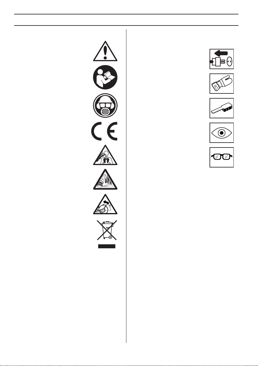
Symbols on the mac hine:
ARNING! The machine can be a
dangerous tool if used incorrectly or
carelessly, which can cause serious or
fatal injury to the operator or others.
Please read the operator’s manual
carefully and make sure you
understand the instructions before
using the machine.
Always wear:
• Approved protective helmet
• Approved hearing protection
• Protective goggles or a visor
This product is in accordance with
applicable EC directives.
WARNING! Dust forms when cutting,
which can cause injuries if inhaled. Use
an approved breathing mask. Always
provide for good ventilation.
WARNING! Sparks from the cutting
blade can cause fire in combustible
materials such as: petrol (gas), wood,
dry grass etc.
WARNING! Kickbacks can be sudden,
rapid and violent and can cause life
threatening injuries. Read and
understand the instructions in the
manual before using the machine.
vironmental marking. Symbols on
the product or its packaging indicate that
this product cannot be handled as
domestic waste. It must instead be
submitted to an appropriate recycling
station for the recovery of electrical and
electronic equipment.
By ensuring that this product is taken care of correctly,
you can help to counteract the potential negative impact
on the environment and people that can otherwise result
through the incorrect waste management of this product.
For more detailed information about recycling this
product, contact your municipality, your domestic waste
service or the shop from where you purchased the
product.
Other symbols/decals on the mac hine refer to special
certification requirements for certain markets.
Symbols in the operator’ s manual:
Inspection and/or maintenance should
be carried out with the motor switched
off and the plug disconnected.
Always wear approved protective
gloves.
Regular cleaning is required.
Visual check.
Protective goggles or a visor must be
worn.
– English

ST
CONTENTS
Contents
KEY TO SYMBOLS
Symbols on the machine: ..................................... 2
Symbols in the operator’s manual: ....................... 2
CONTENTS
Contents ............................................................... 3
WHA T IS WHAT?
What is what on the po wer cutter - K3000? ......... 4
WHA T IS WHAT?
What is what on the po wer cutter - K3000 Wet? .. 5
GENERAL SAFETY PRECA UTIONS
Steps bef ore using a new power cutter ................ 6
Personal protective equipment ............................. 6
Machine ′ s safety equipment ................................. 7
SAFETY INSTR UCTIONS
Gener al safety warnings ....................................... 9
Cutting blades ...................................................... 11
General working instructions ................................ 13
ASSEMBL Y
Assemb ly .............................................................. 15
Fitting the cutting blade ........................................ 15
Guard for the blade ............................................... 15
ARTING AND STOPPING
Bef ore starting ...................................................... 16
Starting ................................................................. 16
Stopping ............................................................... 16
MAINTENANCE
Gener al ................................................................. 17
Cleaning ............................................................... 17
Electrical Feed ...................................................... 17
Replacing the carbon brushes .............................. 17
Bevel gear ............................................................ 18
Checking the drive shaft and flange washers ....... 18
Checking water connection with flow limiter ......... 18
Daily maintenance ................................................ 18
TECHNICAL D ATA
Cutting equipment ................................................ 20
Recommended cable dimensions ........................ 20
EC-declaration of conformity ................................ 21
English
–
3
4
1
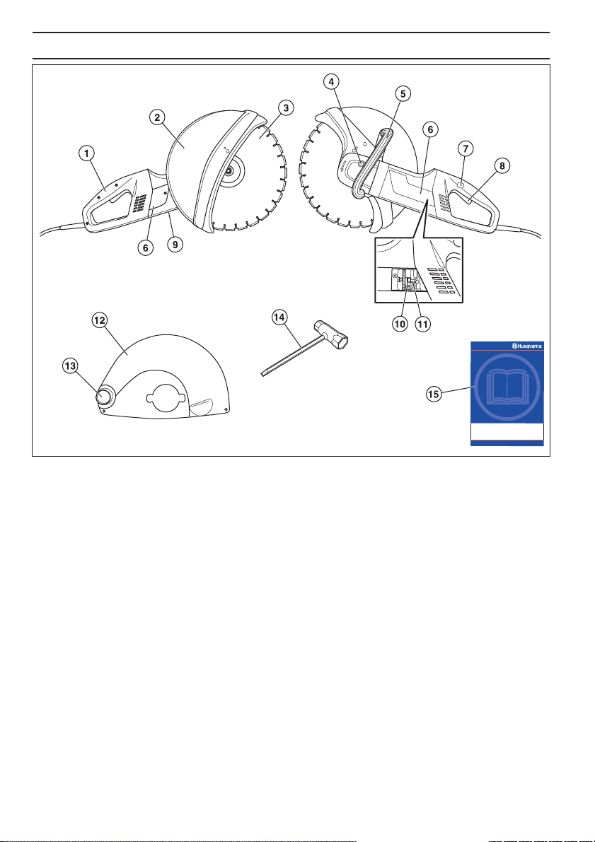
WHA T IS WHA T?
What is what on the po wer cutter - K3000?
Rear handle
2 Guard for the blade 14”
3 Cutting blade
4 Locking the axle
5 Front handle
6 Inspection covers
7 Power switch lock
8 Switch
– English
9 Rating plate
10 Brush retainer
11 Carbon brushes
12 Guard for the blade 12” (Model version)
13 Connection for vacuum cleaner
14 Combination spanner
15 Operator ′ s manual
1
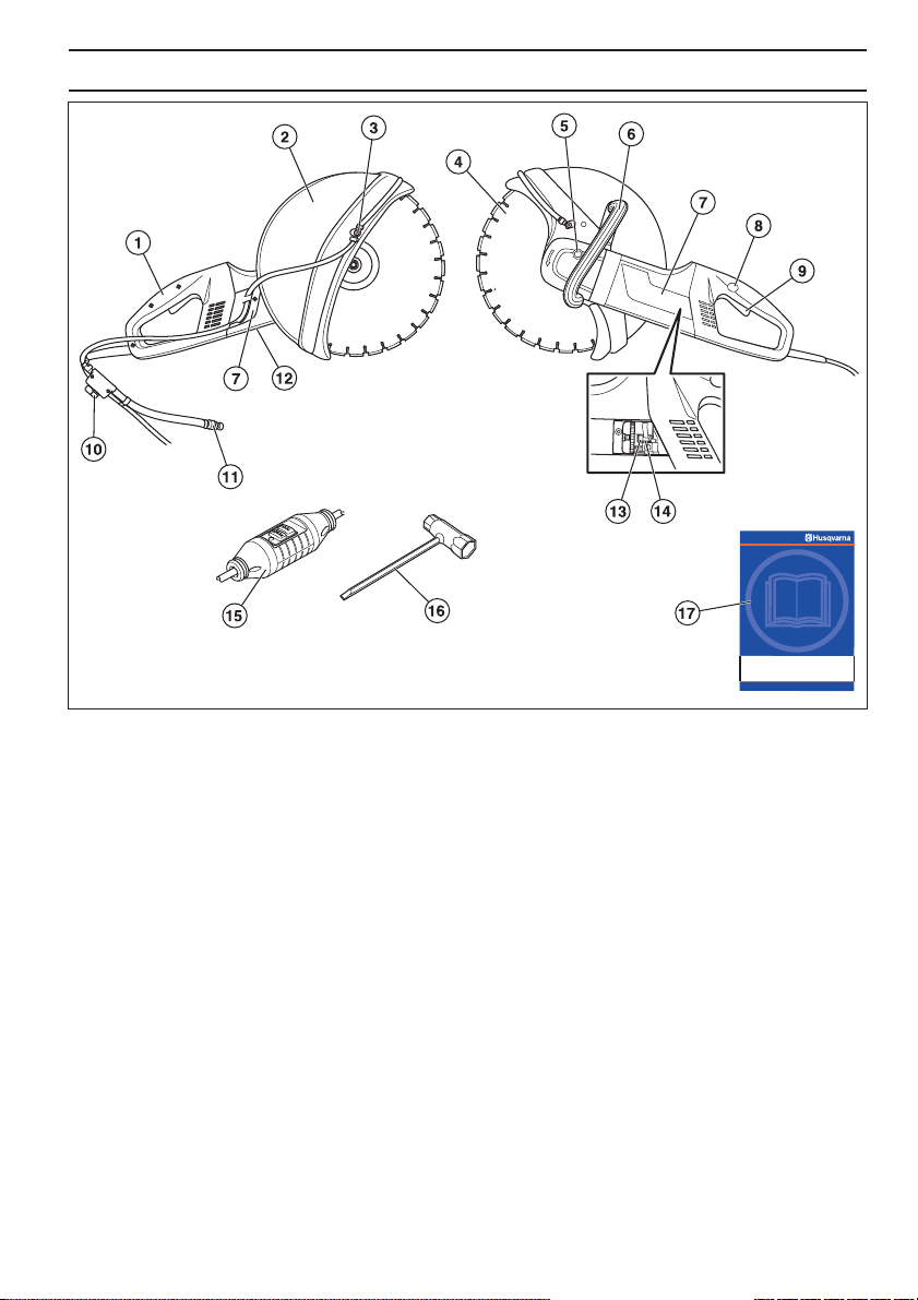
WHA T IS WHA T?
What is what on the po wer cutter - K3000 Wet?
Rear handle
2 Guard for the blade
3 Water kit
4 Cutting blade
5 Locking the axle
6 Front handle
7 Inspection covers
8 Power switch lock
9 Switch
10 Water tap
11 Water connection with flow limiter
12 Rating plate
13 Brush retainer
14 Carbon brushes
15 Ground fault circuit interrupter (not for GB)
16 Combination spanner
17 Operator ′ s manual
English – 5
!
6
•
P
•
W
W
W
GENERAL SAFETY PRECA UTIONS
W
Steps bef ore using a new power cutter
Please read the operator’s manual carefully and make
sure you understand the instructions before using the
machine.
• The machine is only designed for cutting hard
materials, such as concrete, brick, masonry as well as
cast iron and cement pipes.
• Let your Husqvarna dealer regularly check the power
cutter and make essential adjustments and repairs.
ARNING! Under no circumstances
should you modify the original design of
!
the machine without approval from the
manufacturer. Always use original spare
parts. Unauthorized modifications and/or
accessories may lead to serious injury or
death to the user or others.
ARNING! Use of products which cut,
grind, drill, sand or shape material can
!
generate dust and vapors which may
contain harmful chemicals. Know the
nature of the material being worked on
and wear appropriate dust mask or
respirator protection.
ARNING! A power cutter is a
dangerous tool if used carelessly or
!
incorrectly and can cause serious, even
fatal injuries. It is extremely important
that you read and understand the
contents of this Operator’s Manual.
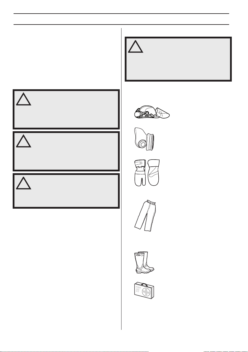
ersonal protective equipment
ARNING! You must use approved
personal protective equipment whenever
you use the machine. Personal protective
equipment cannot eliminate the risk of
injury but it will reduce the degree of
injury if an accident does happen. Ask
your dealer for help in choosing the right
equipment.
Protective helmet
• Hearing protection
• Protective goggles or a visor
• Breathing mask
• Heavy-duty, firm grip gloves.
• Tight-fitting, heavy-duty and comfortable clothing that
permits full freedom of movement.
Husqvarna Construction Products has a policy of
continuous product development. Husqvarna reserves
the right to modify the design and appearance of products
without prior notice and without further obligation
introduce design modifications.
All information and all data in the Operator’s Manual were
applicable at the time the Operator’s Manual was sent to
print.
– English
• Use leg-guards recommended for the material to be
cut.
• Boots with steel toe-caps and non-slip sole.
• Always have a first aid kit nearby.
GENERAL SAFETY PRECA UTIONS
Mac hine ′′
This section descr ibes the machine ′ s safety equipment,
its purpose, and how checks and maintenance should be
carried out to ensure that it operates correctly. See the
”What is what?” section to locate where this equipment is
positioned on your machine.
′′
s safety equipment
ARNING! Never use a machine that has
faulty safety equipment! Carry out the
!
inspection, maintenance and service
routines listed in this section.
All servicing and repair work on the
machine requires special training. This is
especially true of the machine
equipment. If your machine fails any of
the checks described below you must
contact your service agent. When you
buy any of our products we guarantee
the availability of professional repairs
and service. If the retailer who sells your
machine is not a servicing dealer, ask
him for the address of your nearest
service agent.
′′
′′
s safety
•
P
•
W
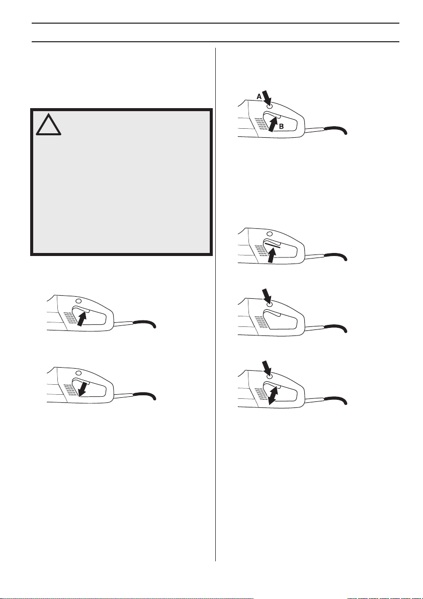
ower switch lock
The po wer switch lock is designed to prevent accidental
operation of the switch. When the lock (A) is pressed in
the power switch (B) is released.
The power switch lock remains depressed as long as the
power switch is depressed. When the grip on the handle
is released both the power switch and power switch lock
are reset. This movement is controlled by two
independent return springs. This position results in the
machine stopping and the power switch being locked.
Chec king the power switch lock
Make sure the power switch is locked when the power
switch lock is in its original position.
Switc h
The po wer switch should be used to start and stop the
machine.
Chec king the power switch
Start the machine, release the power switch and
check that the engine and the cutting blade stop.
• A defective power switch should be replaced by an
authorized service workshop.
• Press in the power switch lock and make sure it
returns to its original position when you release it.
• Check that the power switch and power switch lock
move freely and that the return springs work properly.
• Start the machine, release the power switch and
check that the engine and the cutting blade stop.
Gradual star t and overload protection
The machine is equipped with electronically controlled
gradual start and overload protection.
The engine starts to pulsate if the machine is loaded
above a specific level. If the load is reduced the engine
reverts to its normal state and cutting can resume.
The electronics will cut the current after a set time if the
machine continues to be run with a pulsating engine. The
higher load the faster the shutoff.
The electronics cut the current immediately if the blade
jams.
English
–
7
 Loading...