

Page 1
Page 2
KEY PART
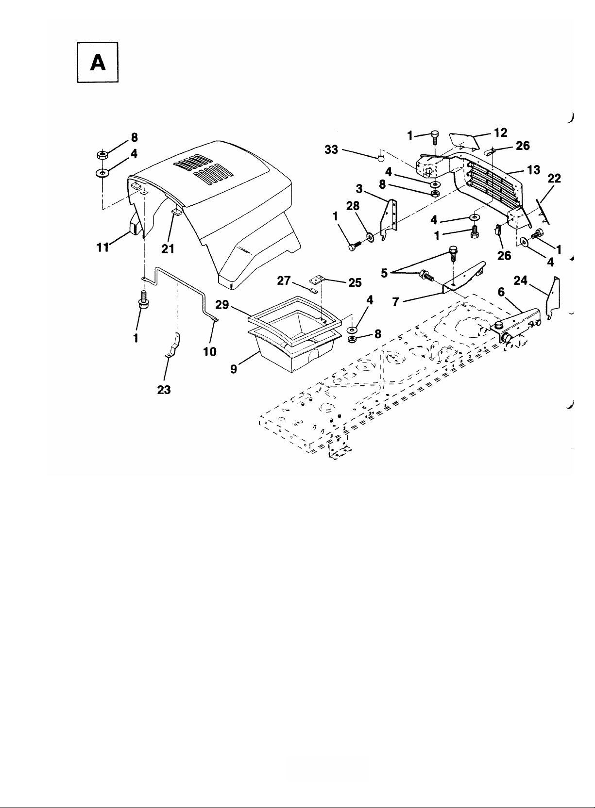
13 532 13 09-84 Grille
NO. NO. DESCRIPTION
1 874 78 04-10 Bolt Fin Hex 1/4-20 x 5/8
3 532 12 84-45 Bracket Pivot Hood LH
4 819 09 10-16 Washer, Flat 1/4
5 817 49 05-12 Screw Thdrol 5/16 -28 x 3/4
6 532 14 00-51 Bracket Asm. Pivot Hood RH
7 532 14 00-50 Bracket Asm. Pivot Hood LH
8 873 22 04-00 Nut Fin Hex 1/4-20
9 532 12 38-40 Duct Air Hood LT112/120
10 532 13 08-50 Brace Hood
11 532 14 01-42 Hood
12 532 13 09-86 Lens LH
KEY PART
NO. NO. DESCRIPTION
21 532 12 69-38 Bumper Hood
22 532 13 09-85 Lens RH
23 532 13 99-69 Latch Hood
24 532 12 84-46 Bracket Pivot Hood RH
25 532 13 10-37 Clip Asm. Duct Air LT112t120
26 532 05 29-21 Clip Tinnerman
27 532 13 10-28 Clip Tinnerman LT112/120
28 811 05 04-00 Washer Lock Ext. Tooth
29 532 12 05-37 Strip Foam LT112/120
33 532 13 13-19 Plug Socket Light LT100/112
HARDWARE SHOWN LARGER FOR EASIER IDENTIFICATION
Page 3
KEY PART
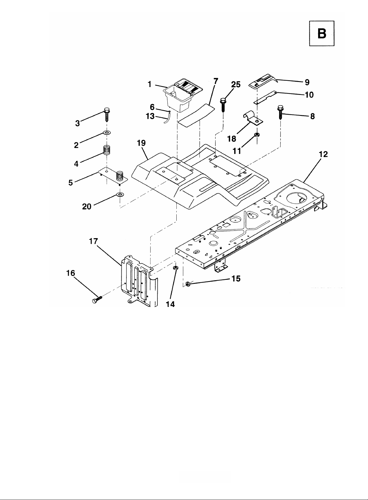
1 532 12 99-65 Case, Battery
NO. NO. DESCRIPTION
2 819 13 20-12 Washer 13/32 x 1-1/4 x 12 Ga.
3 817 49 06-12 Screw, Hex Wsh. Thrdrol
3/8-16x314
4 532 12 41-81 Spring, Compression, Seat
5 532 12 51-42 Plate, Asm. Battery
6 532 10 95-96 Clamp, Hose
7 532 12 41-44 Pad, Footrest
8 817 49 05-12 Screw Thdrol 5/16-18 x 3/4
9 532 12 69-96 Console, Shift Control
10 532 13 97-83 Bar, Shift Lock
KEY PART
NO. NO. DESCRIPTION
11 532 12 43-46 Nut, Self-Threading, Wsher Hd 3/16
12 532 14 07-84 Assembly, Frame
13 532 10 92-38 Tube, Battery Drain
14 873 51 04-00 Nut, Keps 1/4-20 UNC
15 873 68 05-00 Nut, Crownlock 5/16-18
16 874 76 05-12 Bolt, Hex Hd. 5/16-18 UNC x 3/4
17 532 12 78-80 Drawbar
18 532 12 64-70 Clip, Insulated
19 532 12 51-41 Fender/Footrest
20 819 09 14-13 Washer 9/32 x 7/8 x 13 Ga.
25 817 49 05-16 Scr-Hx Wsh Thd Rol 5/16-18 x 1
HARDWARE SHOWN LARGER FOR EASIER IDENTIFICATION
Page 4
KEY PART DESCRIPTION
NO. NO.
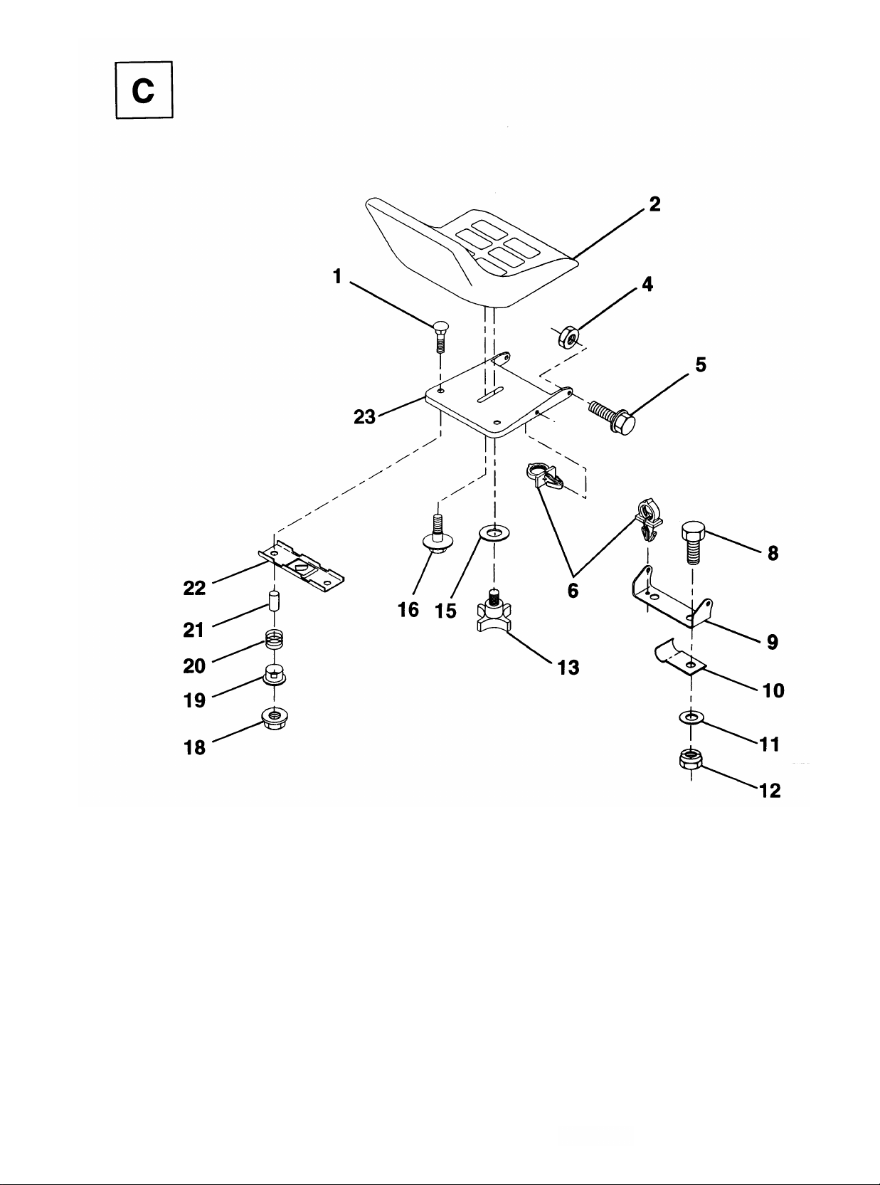
1 872 05 04-11 Bolt, Carriage 1/4-20 x 1-3/8
2 532 12 73-98 Seat
4 873 68 05-00 Nut, Crownlock 5/16-18
5 532 10 55-29 Bolt, Shoulder 5/16-18 UNC
6 532 14 04-07 Clip, Insulated
8 874 76 06-12 Bolt, Fin Hex 3/8-16 UNC x 3/4
9 532 14 05-51 Bracket, Pivot Seat
10 532 12 64-71 Clips, insulated
11 819 13 12-10 Washer12/3 2 x 2 x 10 Ga.
HARDWARE SHOWN LARGER FOR EASIER IDENTIFICATION
KEY PART DESCRIPTION
NO. NO.
12 873 68 06-00 Nut, Crownlock 3/8-16 UNC
13 532 12 00-68 Knob, Seat
15 819 17 19-12 Washer, 17/32 x 1-3/16 x 12 Ga.
16 532 12 70-18 Bolt, Shoulder
18 532 12 39-76 Nut, Hex Large Flange Lock
19 532 12 12-48 Bushing, Snap
20 532 12 12-50 Spring, Compression
21 532 13 43-00 Spacer, Split 28 Id. x .96 Lg.
22 532 12 12-46 Bracket, Switch, Mounting
23 532 14 05-52 Pan, Seat
Page 5
KEY PART
NO. NO. DESCRIPTION
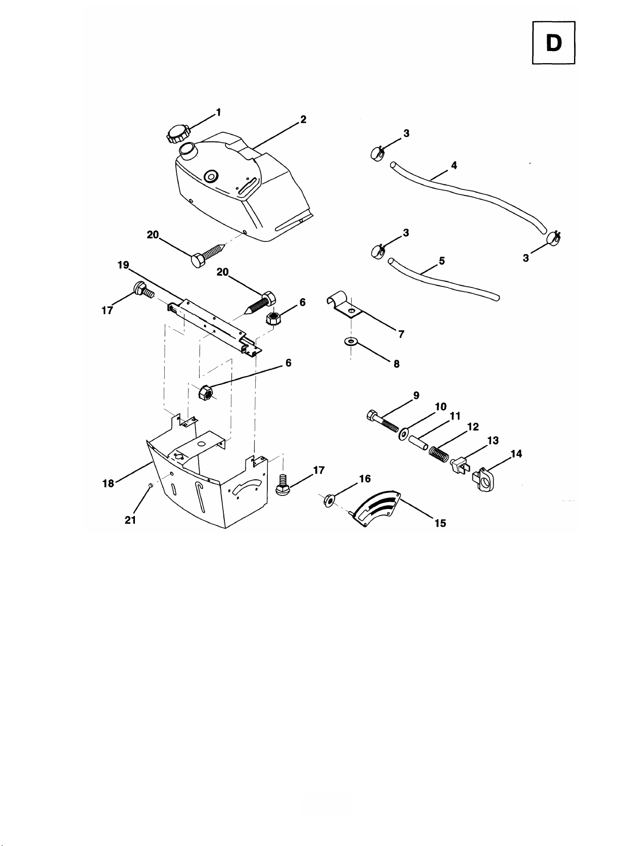
1 532 13 27-35 Cap, Fuel
2 532 13 83-94 Assembly, Dash & Fuel Tank
3 532 12 34-87 Clamp Hose
4 532 00 85-44 Line, Fuel
5 532 00 85-48 Line, Fuel
6 873 51 04-00 Nut, Hex, Keps 1/4-20
7 532 12 49-96 Clip, Fuel Line
8 819 09 12-16 Washer 9/32 x 3/4 x 16 Ga.
9 874 76 04-28 Bolt, Hex, Fin 1/4-20 x 1-3/4
10 819 09 14-13 Washer 11/32 x 11/16 x 16 Ga.
11 532 12 12-49 Spacer, Split
HARDWARE SHOWN LARGER FOR EASIER IDENTIFICATION
KEY PART
NO. NO. DESCRIPTION
12 532 00 37-20 Spring
13 532 12 64-50 Clip, Height Adjustment
14 532 12 61-15 Knob, Height Stop
15 532 12 20-23 Adjustment, Quadrant Height
16 532 12 43-46 Nut, Self-Threading 3/16-18
17 872 11 04-04 Bolt, Carriage 1/4-20 x 1/2 Gr. 5
18 532 13 07-45 Support Assembly, Dash
19 532 13 47-44 Brace, Cross
20 818 00 04-08 Screw, Self-Tapping 1/4-20 x 1/2
21 532 13 40-14 Plug Dome Black
Page 6
KEY PART DESCRIPTION
NO. NO.
KEY PART DESCRIPTION
HARDWARE SHOWN LARGER FOR EASIER IDENTIFICATION
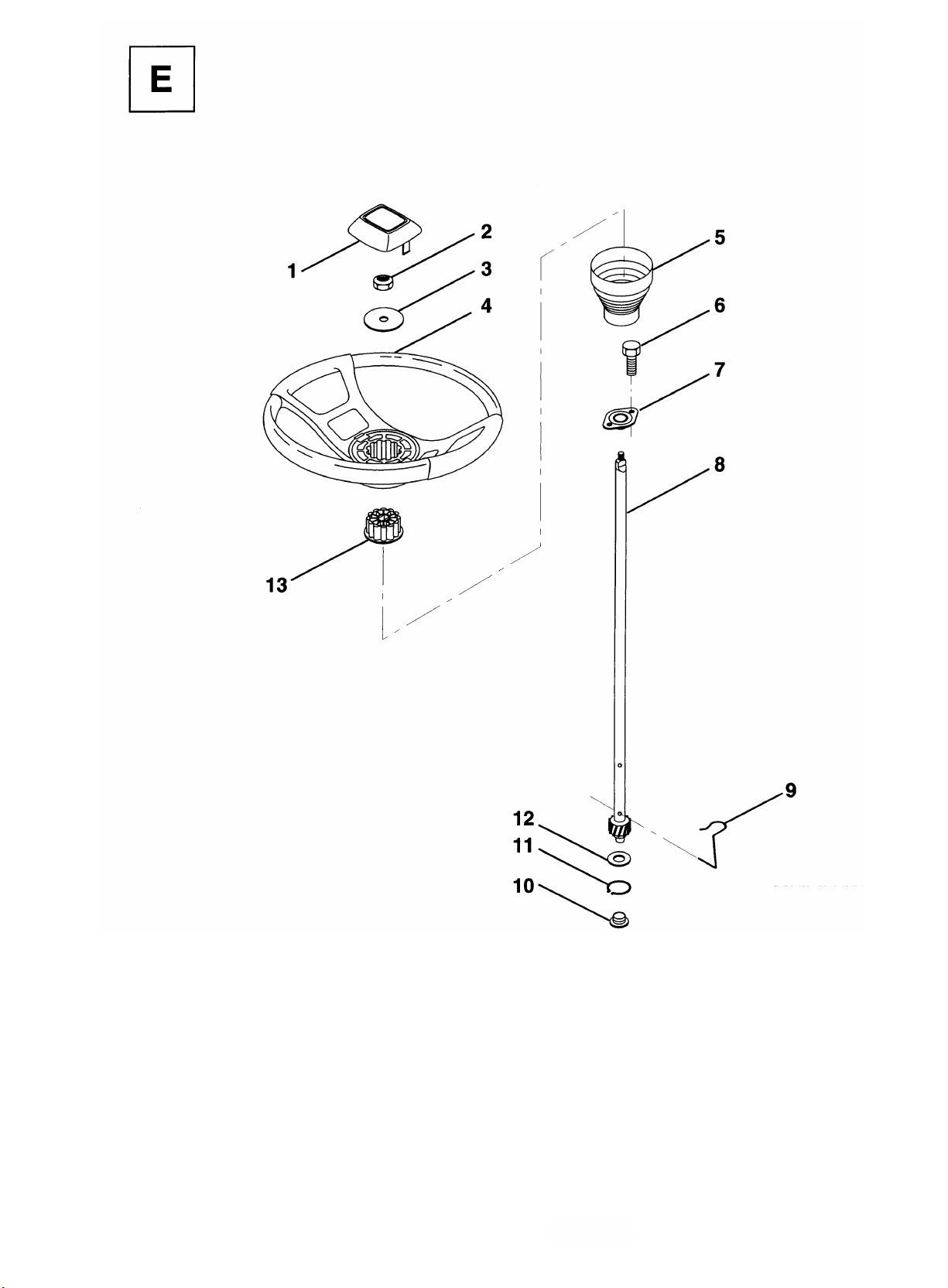
1 532 12 44-16 Insert, Wheel, Steering
2 532 12 47-01 Nut, Lock 3/8-24 UNF
3 819 13 38-08 Washer12/32x2-3/8x8Ga.
4 532 12 44-15 Wheel, Steering
5 532 12 73-96 Sleeve, Steering
6 817 43 10-08 Screw, Hex #10-16 x 1/2 TY-B
7 532 10 28-03 Bushing, Steering
NO. NO.
8 532 12 36-51 Shaft, Steering
9 532 12 42-10 Clip, Steering
10 532 12 34-38 Bushing, Lower, Steering
11 812 00 00-45 Ring, Retaining
12 819 21 16-16 Washer 21/32 x 1 x 16 Ga.
13 532 10 48-20 Adaptor, Wheel, Steering
Page 7

KEY PART DESCRIPTION
NO. NO.
1 874 78 04-08 Screw, Hex Thd. Cut 1/4-20 x 1/2
2 532 13 30-25 Control, Throttle
3 - - - - - - - - Eng ine, Briggs and Stratton Model
No. 286707
4 874 76 05-14 Screw, Hex, Cap 5/16-18x3/4
5 810 04 05-00 Washer, Lock Heavy Helical Spring
5/16
6 532 12 55-93 Gasket, Exhaust
9 819 10 12-16 Washer 5/16 x 3/4 x 16
10 810 04 04-00 Washer, Lock Heavy Helical Spring
HARDWARE SHOWN LARGER FOR EASIER IDENTIFICATION
KEY PART DESCRIPTION
NO. NO.
1/4
11 874 76 04-12 Bolt, Hex Fin.1/4-20 UNC x 3/4
12 532 13 74-37 Muffler
17 817 49 06-24 Screw, Hex Washer Head, Thdrol. 3/
8-16 x 1 -1/2
18 532 12 66-36 Keeper, Ground Drive Belt
20 873 22 06-00 Nut Keps Hex 3/8-16
21 532 12 49-96 Clip Line Fuel
Page 8

KEY PART
NO. NO. DESCRIPTION
1 532 13 25-66 Link, Drag
2 874 78 08-28 Bolt, Fin Hex 1/2-13 x 1-3/4
5 532 12 19-26 Gear, Sector
6 532 12 19-27 Bushing
7 873 03 08-00 Nut, Heavy Hex Top Lock 1/2-13 UNC
8 532 12 64-72 Clip, Insulated
9 873 68 08-00 Nut, Crownlock 3/8-16
10 876 02 04-12 Pin, Cotter 1/8 x 3/4
HARDWARE SHOWN LARGER FOR EASIER IDENTIFICATION
KEY PART
NO. NO. DESCRIPTION
11 819 13 13-16 Washer, 13/32 x 13/16 x 16 Ga.
12 532 12 68-47 Bushing
13 874 76 05-16 Bolt, Hex Hd. 5/16-18 UNC x 1
14 819 11 14-16 Washer11/32x7/8x16Ga.
15 872 11 06-06 Bolt, Carriage 3/8-16 UNC x 3/4
17 532 13 70-96 Support, Front Axle
20 873 80 06-00 Nut, Crownlock 3/8-16 UNC
21 873 68 05-00 Nut, Crownlock 5/16-18
Page 9

KEY PART DESCRIPTION
NO. NO.
1 532 12 12-32 Cap, Spindle
2 812 00 00-29 Ring Clip
3 532 12 17-48 washer 25/32 x1-5/8 x16 Ga.
4 532 12 49-37 Bearing Col Strg.
5 532 14 02-12 Axle Front
6 532 12 49-31 Bearing, Thrust
7 532 13 70-62 Spindle, R.H. Asm.
8 532 12 17-49 Washer 25/32 x 1-1/4 x 16 Ga.
9 876 02 04-12 Pin, Cotter 1/8 x 3/4
HARDWARE SHOWN LARGER FOR EASIER IDENTIFICATION
KEY PART DESCRIPTION
NO. NO.
10 819 13 13-16 Washer 13/32x13/16x 16Ga.
11 532 12 68-47 Bushing
12 532 13 04-65 Rod, Tie
13 532 13 70-61 Spindle, L.H. Asm.
14 874 01 10-56 Bolt Hex 5/8-11 x 3-1/2
15 873 90 10-00 Locknut Flange 5/8-11
16 532 14 02-47 Spacer Bearing
17 532 12 48-36 Fitting Grease
18 819 27 20-16 Washer 27/32 x 1-1/4 x 16 Ga.
Page 10

KEY PART
NO. NO. DESCRIPTION
1 532 07 16-73 Cap, Plunger
2 532 12 34-36 Rod, Parking Brake
3 532 12 34-37 Bracket, Parking Brake
4 532 00 81-56 Cover, Pedal
5 532 12 25-04 Bracket, Clutch/Brake Pedal, L.H.
6 876 02 03-12 Pin, Cotter 3132x314
7 819 13 10-16 Washer 13/32x 5/8x16Ga.
8 817 49 05-08 Screw, Hex, Thd. Roll.
5/16-18x112
9 876 02 04-12 Pin, Cotter 1/8 x 3/4
10 819 13 13-16 Washer 13/32 x 13/16 x 16 Ga.
11 532 12 35-43 Rod, Brake Front
12 532 13 99-33 Assembly, Clutch/Brake Pedal
13 532 12 33-94 Rod, Clutch
14 532 12 19-78 Bracket, Lift, Shaft
15 532 12 36-41 Assembly, Brake, Pivot, Arm
HARDWARE SHOWN LARGER FOR EASIER IDENTIFICATION
KEY PART
NO. NO. DESCRIPTION
16 819 25 18-16 Washer 25/32 x 1-1/8 x 16 Ga.
17 812 00 00-34 Ring, Klip
18 532 10 68-88 Spring, Brake Rod
19 873 35 06-00 Nut, Hex, Jam 3/8-16 UNC
20 873 80 06-00 Locknut, Hex w/Washer Insert
3/8-16 UNC
21 532 13 14-60 Rod, Rear Brake
22 532 12 73-78 Trunnion, Lift
23 873 68 06-00 Nut, Crownlock 3/8-16 UNC
24 819 13 20-12 Washer 13/32 x 1-1/4 x 12 Ga.
25 532 00 49-21 Spring, Retainer
26 873 93 06-00 Nut, Centerlock 318-16 UNC
27 532 12 73-69 Link, Threaded
28 532 12 73-58 Assembly, Rear Mower Lift
29 872 11 05-06 Bolt, Carriage 5/16-18 UNC x 3/4
30 873 51 05-00 Nut, Keps 5/16-16 UNC
Page 11

KEY PART
1 873 68 05-00 Nut, Crownlock 5/16-18
13 819 13 13-16 Washer 13/32 x 13/16 x 16 Ga.
NO. NO. DESCRIPTION
KEY PART
NO. NO. DESCRIPTION
2 874 76 05-12 Bolt, Hex Hd 5/16-18 UNC x 3/4
3 532 13 12-05 Keeper, Mower Drive, R. H.
4 532 13 80-29 Pulley, Engine
5 810 04 07-00 Washer, Lock 7/16
6 871 17 07-44 Bolt Hex 7/16-20 Gr. 5
7 532 12 65-20 Traction, V-Belt Drive
8 532 12 34-05 Keeper, T/A Ground Drive Belt
9 872 14 06-12 Bolt, Carr. 3/8-16 UNC x 1-1/2
10 532 12 33-96 Keeper, Belt Ground Drive Idler
11 532 12 33-95 Arm, Ground Drive Clutch
12 532 12 36-74 Idler, Flat
HARDWARE SHOWN LARGER FOR EASIER IDENTIFICATION
14 873 93 06-00 Nut, Centerlock 3/8-16UNC
15 873 68 06-00 Nut, Crownlock 3/8-16 UNC
16 532 12 64-71 Clip, Insulated
17 532 12 20-52 Spacer, Retainer
18 532 13 14-59 Spring Extension
19 873 51 05-00 Nut, Keps 5/16-18 UNC
20 532 13 99-19 Keeper, T/A Ground Drive Belt
21 819 11 10-16 Washer 11/32 x 5/8 x 16 Ga.
22 532 12 34-04 Keeper, Frame Ground Drive Belt
23 532 13 12-04 Keeper, Mower Drive, L. H.
Page 12

KEY PART DESCRIPTION
NO. NO.
1 532 12 33-85 Pulley
2 812 00 00-28 Ring, Retainer
4 532 12 50-96 Key, Woodruff #9
5 873 68 05-00 Nut, Crownlock 5/16-18
6 872 14 05-06 Bolt, Carriage 5/16-18 UNC x 3/4
7 532 12 33-78 Strap, Torque
8 817 49 05-12 Screw 5/16-18 x 3/4
9 532 11 04-22 Spring, Brake
10 532 12 17-49 Washer 25/32 x 1-1/4 x 16 Ga.
11 532 12 35-83 Key, Square
12 874 76 05-40 Bolt, Fin Hex 5/16-18 x 2-1/2
15 819 17 16-16 Washer 17/32 x 1 x 16 Ga.
16 532 12 46-00 Support Handle Shift LH
17 532 12 62-93 Link, Shift
18 871 04 04-12 Bolt, Fin Hex 1/4-28 UNF x 3/4 Gr.
8
HARDWARE SHOWN LARGER FOR EASIER IDENTIFICATION
KEY PART DESCRIPTION
NO. NO.
19 810 04 04-00 Washer, Lock 1/4
20 819 09 12-10 Washer 9/32 x 3/4 x 10 Ga.
21 532 12 62-92 Arm, Shift
22 532 10 57-01 Washer, Shift Plate
23 532 12 12-74 Knob, Duckhead LT120
23 532 10 69-33 Knob LT100/112
24 532 12 82-15 Rod, Shift
25 876 02 04-16 Pin, Cotter 1/8x1
26 873 81 05-00 Locknut 5/16-24 UNF
27 873 51 05-00 Nut, Keps 5/16-18
28 532 12 80-85 Extension, Sprinq
29 532 12 80-84 Support Handle Shift RH
31 532 13 70-57 Spacer Axle
32 819 11 11-16 Washer 11/32 x 11/16 x 16 Ga.
34 811 05 05-00 Washer External Tooth 5/16
35 812 00 00-01 E-Ring '
Page 13

KEY PART DESCRIPTION
NO. NO.
1 532 12 64-70 Clip, Insulated
2 532 12 20-18 Bracket, Mower Clutch
3 874 78 04-08 Bolt, Fin. Hex
1/4-20 UNC x 1/2Gr.5
4 873 80 06-00 Nut, Crownlock 3/8-16UNC
5 532 12 34-17 Assembly, Clutch Lever
6 532 10 64-51 Bolt, Shoulder
7 532 13 53-71 Assembly, Mower Clutch Arm
8 874 76 06-36 Bolt, Hex 3/8-16 UNC x 2-1/4
9 532 12 19-30 Assembly, Bellcrank Lift
10 876 02 04-12 Pin, Cotter 1/8 x 3/4
11 819 13 13-16 Washer 13/32 x 13/16 x 16 Ga
12 532 13 18-61 Grip handle LT100/112
12 532 12 20-27 Grip, Handle LT 120
r 13 532 13 93-52 Assembly, Lift Handle
HARDWARE SHOWN LARGER FOR EASIER IDENTIFICATION
KEY PART DESCRIPTION
NO. NO.
14 532 12 34-96 Spring, Compression
15 819 13 12-12 Washer 13/32x314x 12Ga.
16 532 00 49-21 Retainer, Spring
17 532 12 73-59 Link, Front Lift
18 532 13 32-05 Trunnion, Threaded 3/8-16
19 873 68 04-00 Nut, Crownlock 1/4-20
20 874 76 06-44 Bolt, Fin. Hex
3/8-16 UNC x 2-3/4
23 876 02 04-16 Pin, Cotter 1/8x1
24 819 17 16-16 Washer 17/32x1x16Ga.
25 532 12 19-33 Tube, Spacer
26 532 12 19-34 Rod, Mower Lift
27 532 10 69-32 Knob LT 100/112
27 532 12 14-66 Knob LT120
28 876 02 03-12 Pin, Cotter 3/32x3/4
29 532 13 16-55 Link, Mower Clutch
30 873 35 06-00 Nut Hex Jam 3/8-16
Page 14

Page 15

KEY PART DESCRIPTION
NO. NO.
HARDWARE SHOWN LARGER FOR EASIER IDENTIFICATION
KEY PART DESCRIPTION
1 532 14 00-64 Spring, Mower Clutch
2 532 12 20-52 Spacer, Retainer
3 873 80 06-00 Nut, Crownlock
4 532 13 08-40 Brake Asm.
5 532 13 12-51 Guide, Belt Idler
6 532 12 13-16 Pulley, Flat Idler
7 872 11 06-16 Bolt, Carr. 3/8-16 x 1 -3/4 Gr. 5
8 819 13 14-10 Washer 13/21 x 7/8 x 10 Ga.
9 532 14 00-92 Arm Asm., Idler Mower
10 872 11 06-08 Bolt, Carriage 3/8-16x 1
11 532 13 08-41 Rod, Brake
12 532 12 73-56 Bracket, Lift R. H. Rear
13 872 14 05-05 Bolt, Carriage 5/16-18 x 5/8
14 873 68 05-00 Nut, Crownlock 5/16-18
15 532 12 73-57 Bracket, Lift L. H. Rear
16 532 14 00-93 Keeper, R. H.
17 532 12 85-08 Link, Asm. Mower Stabilizer
18 532 12 85-11 Pin, Drive
19 532 12 73-80 Bracket, Asm. Front
20 532 14 01-01 Blade, Mulching
20 532 12 78-41 Blade, Hi-Lift
21 532 14 02-96 Washer, Hard
22 810 03 06-00 Washer, Lock 3/8
23 532 85 08-57 Bolt 3/8-24 x 1-1/4 Gr. 8
24 532 14 03-29 Stripper
25 873 76 05-28 Bolt 5/16-18 x 1-1/4
NO. NO.
26 532 12 99-63 Washer .150 Thk.
27 532 12 99-83 Deck Assembly
28 532 12 92-07 Pulley, Mandrell
29 873 05 09-00 Nut
30 532 13 66-31 Bracket, Asm. Deflector
31 817 49 05-08 Screw, Hex Wsh. Thdrol.
5/16-18 x 1/2
32 532 12 20-51 Arm, Support Idler Mower
33 532 13 15-60 Deflector
36 532 12 19-80 Rod, Hinge
37 532 12 37-13 Spring, Torsion Deflector
38 532 10 53-04 Cap, Sleeve
39 819 11 10-16 Washer 11/32 x 5/8 x 16 Ga.
40 532 11 04-52 Pushnut
41 532 13 12-64 V-Belt
42 819 17 16-16 Washer 11/32 x 5/8 16 Ga.
43 532 12 46-60 Retainer, Spring
44 532 14 06-08 Keeper, L. H.
45 532 11 04-85 Bearing
46 532 12 87-74 Housing Mandrel Vented
47 532 12 98-95 Bearing
48 532 13 76-45 Shaft, Mandrel (Includes Key # 47)
- - 532 13 07-94 Mandrel Asm. (Includes Key No.'s
22-23, 26, 29 and 45-48)
- - 532 14 09-79 Deck, Mower Complete
49 532 13 39-43 Washer Wear 16 Ga.
Page 16

KEY PART DESCRIPTION
NO. NO.
1 873 51 04-00 Nut, Hex Keps 1/4-20
2 532 10 84-23 Assembly, Cable
3 532 13 39-09 Battery
5 532 10 82-36 Bracket, Switch
6 532 10 95-53 Switch Interlock (4-terminal)
7 532 10 44-45 Switch Interlock (2-terminal)
8 817 02 10-08 Screw, Hex Hd. Tap #10-24 x 1/2
9 532 14 04-01 Key, Molded
10 532 12 36-20 Cover, Key Ignition
11 532 14 04-00 Nut, Ignition
12 532 14 03-99 Switch, lgnition
14 532 12 47-56 Tie, Cable
15 532 12 13-05 Switch, Plunger
16 873 51 05-00 Nut, Hex, Keps 5/16-18
17 532 10 88-24 Fuse
18 532 12 83-53 Assembly, Cable
19 532 14 04-10 Harness, lgnition LT100/112
19 532 14 04-11 Harness. lgnition LT120
KEY PART DESCRIPTION
NO. NO.
20 873 35 04-00 Nut, Hex Jam 1/4-20
21 810 09 04-00 Washer, Lock 1/4
22 874 78 04-08 Bolt, Fin. Hex
1/4-20 UNC x 1/2 Gr. 5
24 532 13 15-63 Cover, Terminal
25 532 13 84-06 Solenoid
26 874 76 04-12 Bolt, Hex Hd. 1/4-20 UNC x 3/4
27 819 09 10-16 Washer 9/32 x 5/8 x 16
28 810 04 04-00 Washer, Lock 1/4
29 532 12 12-64 Cap, Battery
30 873 22 04-00 Nut, Fin. Hex 1/4-20 UNC
31 532 00 41-52 Bulb Light, LT120
32 532 13 10-78 Harness Headlight LT120
33 532 11 07-12 Switch Light LT120
35 811 05 06-00 Washer Lock Ext. Tooth 3/8
36 810 04 04-00 Washer Lock Inter. Tooth 1/4
37 532 14 04-13 Harness Engine
38 532 14 06-60 Harness Adapter
Page 17

KEY PART DESCRIPTION
NO. NO.
1 532 12 90-57 Decal, HP, Engine LT120
3 532 14 02-06 Decal, Hood, L. H.
4 532 14 02-05 Decal, Hood, R. H.
5 532 14 02-13 Decal, Logo, Grill
8 532 13 15-82 Decal, Logo, Fender
9 532 12 61-87 Decal, Certification
(French/Dutch)
10 532 13 37-95 Decal Caution Fender
11 532 13 72-59 Decal, Warning
13 532 12 15-49 Decal, Caution, Battery
14 532 12 61-93 Decal, Caution, Deflector,
(Swedish/Danish/Finnish/Norwegian)
- - 532 12 63-47 Decal, Caution, Deflector,
(Spanish/ltalian)
KEY PART DESCRIPTION
NO. NO.
15 532 14 01-62 Decal, Instruction, Warning,
(Multi-Lang.)
- - 532 13 82-70 Decal, Instruction Warning
(Swedish/Danish/Finnish/Norwegian)
- - 532 12 63-48 Decal, Instruction, Warning,
(Spanish/ltalian)
16 532 13 68-30 Decal, V-Belt Schematic
17 532 14 02-01 Decal, Hood R.H LT100
17 532 14 02-03 Decal Hood R.H LT112
17 532 14 01-99 Decal HoodR.HLT120
18 532 14 02-02 Decal, Hood L.H LT100
18 532 14 02-04 Decal, Hood L.H LT112
18 532 14 02-00 Decal, Hood L.H LT120
- - 532 13 82-69 Decal, Inst. Oper. (English/French)
KEY PART DESCRIPTION
NO. NO.
1 532 05 91-92 Cap, Valve
2 532 06 51-39 Stem, Valve
3 532 12 49-57 Fitting, Grease\ (Front Wheels)
4 532 12 34-10 Tire, Front LT100/112
4 532 30 11-40 Tire, Front LT120
4 506 80 27-01 Tire, Rear LT100/112
4 532 13 27-03 Tire, Rear LT120
5 532 05 99-04 Tube, Front
5 532 00 81-34 Tube, Rear
6 532 14 02-98 Rim, Front
6 532 14 04-53 Rim, Rear
7 532 10 47-57 Cap, Hub LT100/112
7 532 12 45-77 Cap, Hub Front LT120
7 532 12 45-78 Cap, Hub Rear LT120
8 532 12 49-59 Bearing Flange
9 532 12 17-48 Washer 25/32 x 1 -5/8 x 16 Ga.
Page 18

KEY PART DESCRIPTION
KEY PART DESCRIPTION
NO. NO.
2 532 06 91-80 Locknut # 10-24
3 532 12 75-33 Screen, Cover
4 532 14 06-54 Cover
5 532 12 85-98 Chute, Upper
6 818 02 10-08 Screw, Special
7 532 14 05-72 Indicator, Dump Bag
8 532 08 71-75 Screw, # 10-24 x 1-1/8
9 734 11 46-01 Washer 3/16 x 3/4 x 16 Ga
10 532 00 72-06 Spacer, Split
11 532 06 08-67 Nut, Acorn # 10-24
12 810 07 10-00 Washer, lock
13 532 10 98-08 Latch, Chute
14 532 12 50-04 Nut, Weld
15 874 93 05-16 Bolt, Hex 5/16-18 x 1
17 532 13 07-58 Latch Assy., Bagger
18 532 12 85-99 Chute, Lower
19 532 13 38-41 Nut, Acorn 5/16-18
20 874 29 10-10 Screw # 10-24 x 5/8
21 532 13 27-96 Spring, Cover L.H. (black)
22 532 13 32-35 Spacer, Cover
23 532 13 29-83 Spring, Cover R.H. (gray)
NO. NO.
24 532 12 77-20 Post, Support
25 873 22 05-00 Locknut 5/16 x 18
26 532 12 46-70 Spring, Retainer
27 874 76 05-12 Bolt, Hex 5/16-18 x 3/4
28 532 13 08-89 Bracket, Mounting
29 817 49 05-08 Screw, Thread Rolling 5/16-18 x 1/2
30 532 13 11-37 Pin, Support Post
31 532 13 44-96 Cap, Tubing End
32 532 12 69-19 Bagger, Frame
33 532 12 86-00 Pin, Hinge
34 532 12 75-34 Gasket, Cover
35 532 12 95-85 Container, Top
36 532 12 95-86 Container, Bottom, Hard
36 532 13 24-31 Container, Bottom, Soft
37 532 13 22-56 Seal, Cover
38 532 13 08-95 Latch Handle, Cover
39 532 13 54-95 Strip, Seal
40 874 19 10-08 Screw # 10-24 x 112
41 873 80 06-00 Locknut 3/8-16
42 532 13 70-31 U-Bolt
43 532 12 36-35 Weight, Wheel
Page 19

Page 20

 Loading...