

Page 1

Oper ator ′ s manual
K3600 MKII
Please r ead the operator’s manual carefully and make sure you understand the
instructions before using the machine.
EEEEnnnngggglllliiiisssshh
hh
Page 2
2
K
ey to symbols
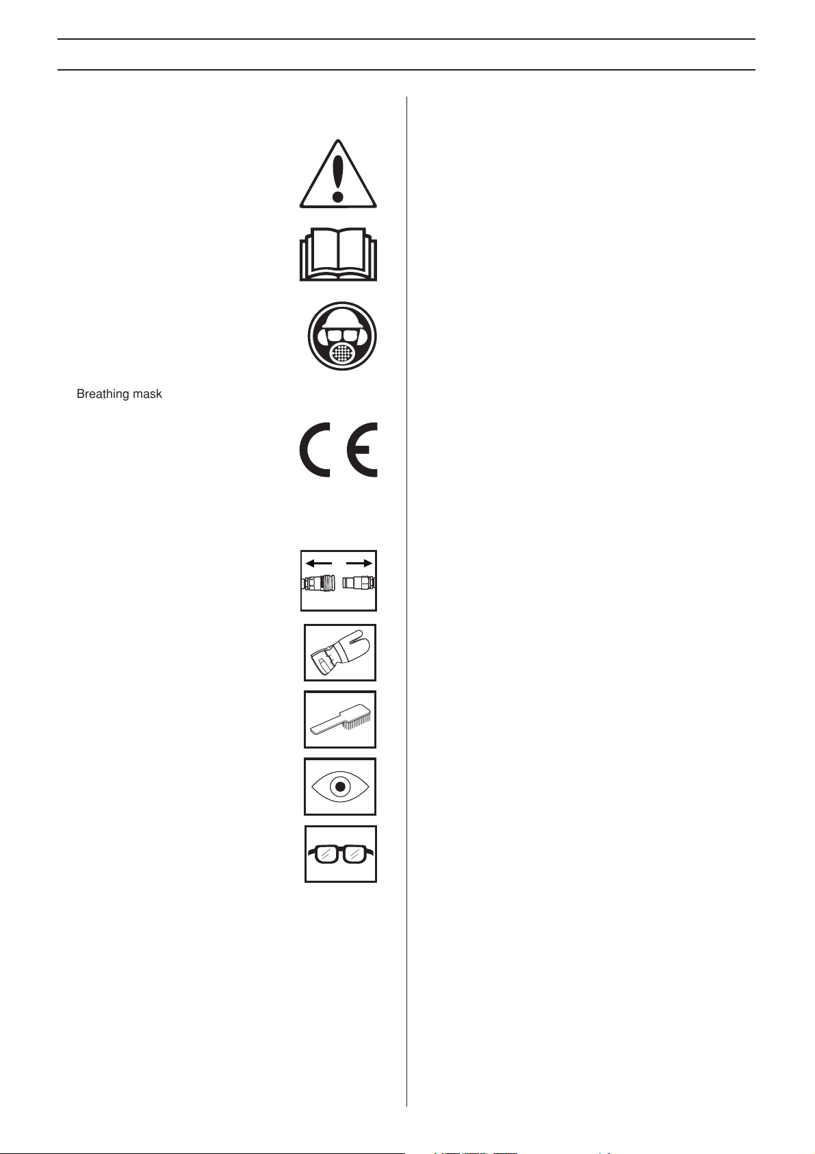
WARNING! The machine can be a
dangerous tool if used incorrectly or
carelessly, which can cause serious or
fatal injury to the operator or others.
Please read the oper ator’s manual
carefully and make sure you understand
the instructions before using the machine.
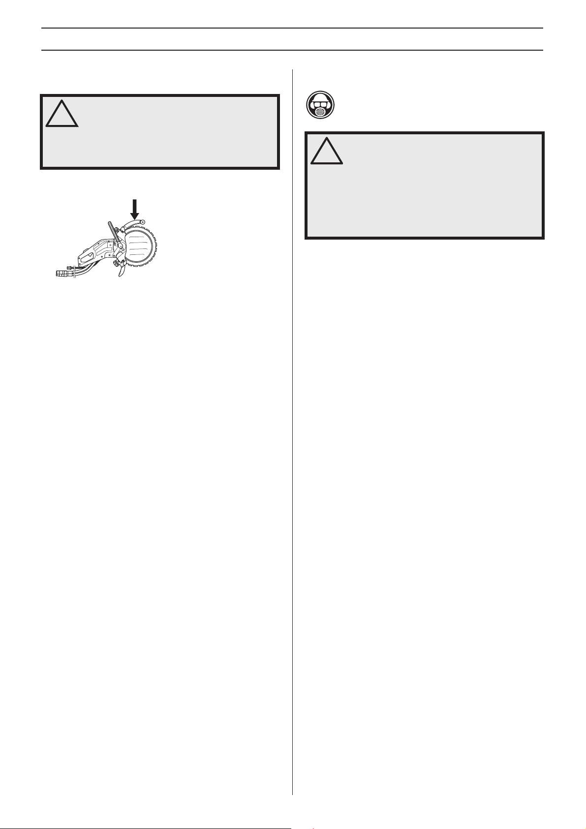
Always wear:
• Approved protective helmet
• Approved hearing protection
• Protective goggles or a visor
• Breathing mask
KEY T O SYMBOLS
This product is in accordance with
applicable EC directives.
Other symbols/decals on the mac hine refer to special
certification requirements for certain markets.
Alw ays disconnect the machine from the
hydraulic hoses before inspection and/or
maintenance of the machine.
Alw ays wear approved protective gloves.
Regular cleaning is required.
Visual chec k.
Protectiv e goggles or a visor must be worn.
–
English
Page 3

K
Dr
ST
TR
CONTENTS
Contents
KEY TO SYMBOLS
ey to symbols ............................................................. 2
CONTENTS
Contents ...................................................................... 3
WHA T IS WHAT?
What is what on the po wer cutter? ............................... 4
SAFETY INSTR UCTIONS
Steps bef ore using a new power cutter. ....................... 5
Personal protective equipment ..................................... 5
Machine ′ s safety equipment ........................................ 5
Checking, maintaining and servicing the machine ′ s
safety equipment .......................................................... 6
General safety precautions .......................................... 7
General working instructions ....................................... 7
SETTINGS AND ADJUSTMENTS
ive ............................................................................. 11
Fitting the blade ........................................................... 11
Hydraulic hoses ........................................................... 13
Water hose ................................................................... 13
Water supply ................................................................ 13
Water dosage ............................................................... 13
ARTING AND STOPPING
Star ting and stopping ................................................... 14
MAINTENANCE
Maintenance ................................................................ 15
Dismantling the complete guide roller .......................... 15
Assembling the complete guide roller .......................... 15
Drive wheel .................................................................. 16
Replacing the support rollers/guide rollers .................. 16
Reconstructing the blade ............................................. 17
Couplings ..................................................................... 17
Hydraulic hoses ........................................................... 17
Maintenance schedule ................................................. 18
Blades conforming to EN13236 ................................... 18
OUBLE SHOOTING
Mechanics .................................................................... 19
TECHNICAL D ATA
Extending the h ydraulic hoses ..................................... 20
EC-declaration of conformity ........................................ 21
English
– 3
Page 4
4
1
WHA T IS WHA T?
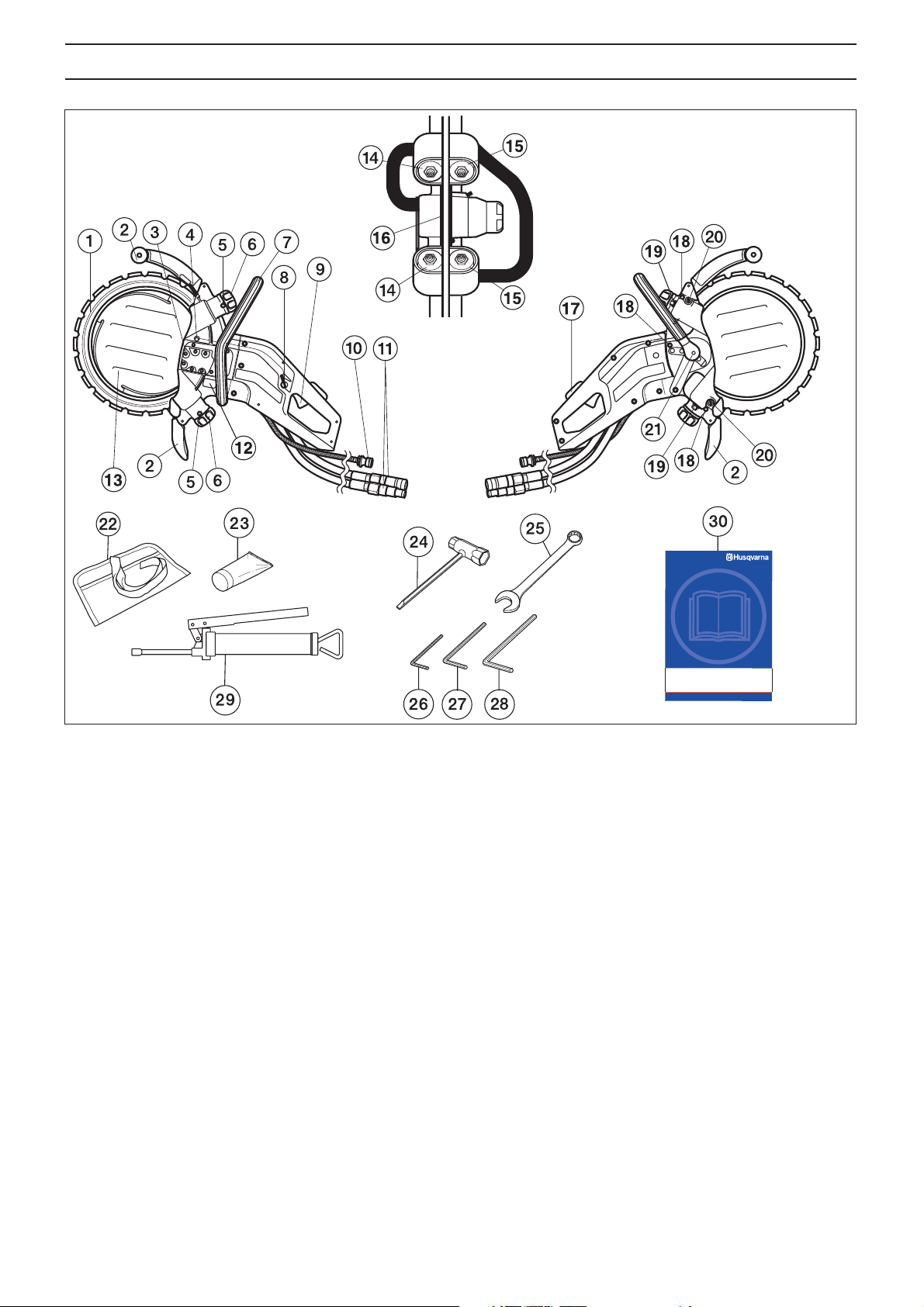
What is what on the po wer cutter?
Diamond blade
2 Blade guard/spray guard
3 Hydraulic motor
4 Locking button for the drive wheel
5 Grease nipples
6 Control for the guide rollers
7 Front handle (adjustable)
8 Water adjustment control
9 Switch
10 Water connector
11 Couplings for hydraulic hoses
12 Rating plate
13 Water disc
14 Support rollers
15 Guide rollers
16 Drive wheel
17 Switch lock and ON/OFF valve for the water
18 Cover screws
19 Locking nuts for the support rollers
20 Adjuster screws
21 Switch lock for the front handle
22 Tool bag
23 Bearing grease
24 Combination spanner
25 19 mm combination spanner
26 4 mm hex key
27 5 mm hex key
28 6 mm hex key
29 Grease gun
30 Operator ′ s manual
–
English
Page 5
•
P
•
W
W
SAFETY INSTR UCTIONS
W
W
W
Steps bef ore using a new power cutter.
This machine is a hydraulically operated power cutter
intended for free-hand cutting. The machine should be
connected to a hydraulic unit with an oil flow of 35-42
litres/min and a maximum pressure of 150 bar.
• Please read the operator’s manual carefully.
• Check the cutting blade’s mounting, see the chapter
”Assembly”.
Let your Husqvarna dealer check the power cutter and make
essential adjustments and repairs.
ARNING! Under no circumstances may the
design of the machine be modified without
!
the permission of the manufacturer. Always
use genuine accessories. Non-authorized
modifications and/or accessories can result
in serious personal injury or the death of the
operator or others.
ARNING! Use of products which cut, grind,
drill, sand or shape material can generate
!
dust and vapors which may contain harmful
chemicals. Know the nature of the material
being worked on and wear appropriate dust
mask or respirator protection.
• Breathing mask
• Heavy-duty, firm grip gloves.
• Tight-fitting, heavy-duty and comfortable clothing that
permits full freedom of movement.
• Use leg-guards recommended for the material to be cut.
• Boots with steel toe-caps and non-slip sole
ARNING! A power cutter is a dangerous
tool if used carelessly or incorrectly and can
!
cause serious, even fatal injuries. It is
extremely important that you read and
understand the contents of this Operator’s
Manual.
Husqvarna Construction Products has a policy of continuous
product development. Husqvarna reserves the right to modify
the design and appearance of products without prior notice
and without further obligation introduce design modifications.
All information and all data in the Operator’s Manual were
applicable at the time the Operator’s Manual was sent to print.
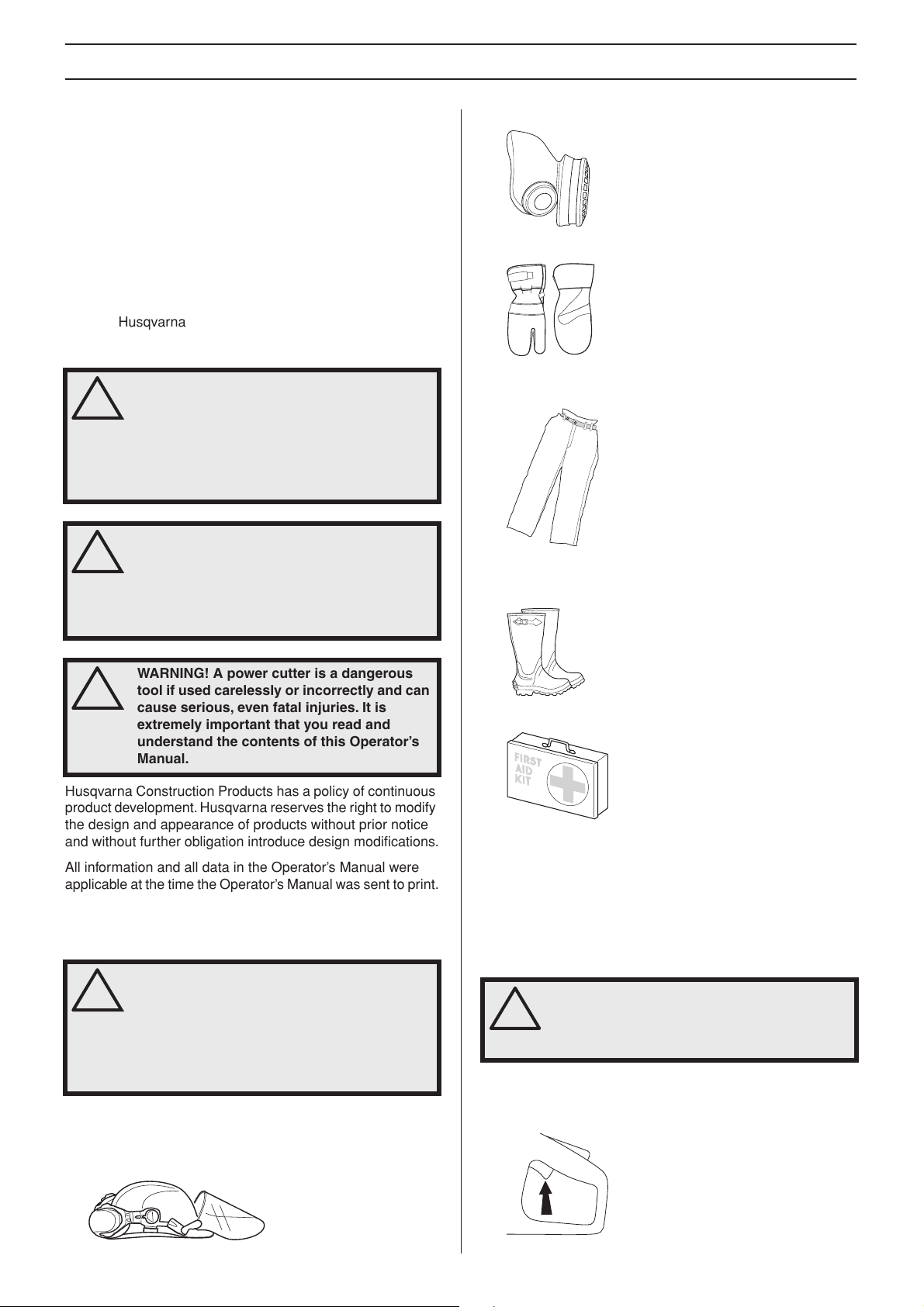
ersonal protective equipment
ARNING! You must use approved personal
protective equipment whenever you use the
!
machine. Personal protective equipment
cannot eliminate the risk of injury but it will
reduce the degree of injury if an accident
does happen. Ask your dealer for help in
choosing the right equipment.
Protective helmet
• Hearing protection
• Protective goggles or a visor
• Always have a first aid kit nearby.
Mac hine ′′
This section descr ibes the machine ′ s safety equipment, its
purpose, and how checks and maintenance should be carried
out to ensure that it operates correctly. See the ”What is
what?” section to locate where this equipment is positioned
on your machine.
!
′′
s safety equipment
ARNING! Never use a machine that has
faulty safety equipment! Carry out the
inspection, maintenance and service
routines listed in this section.
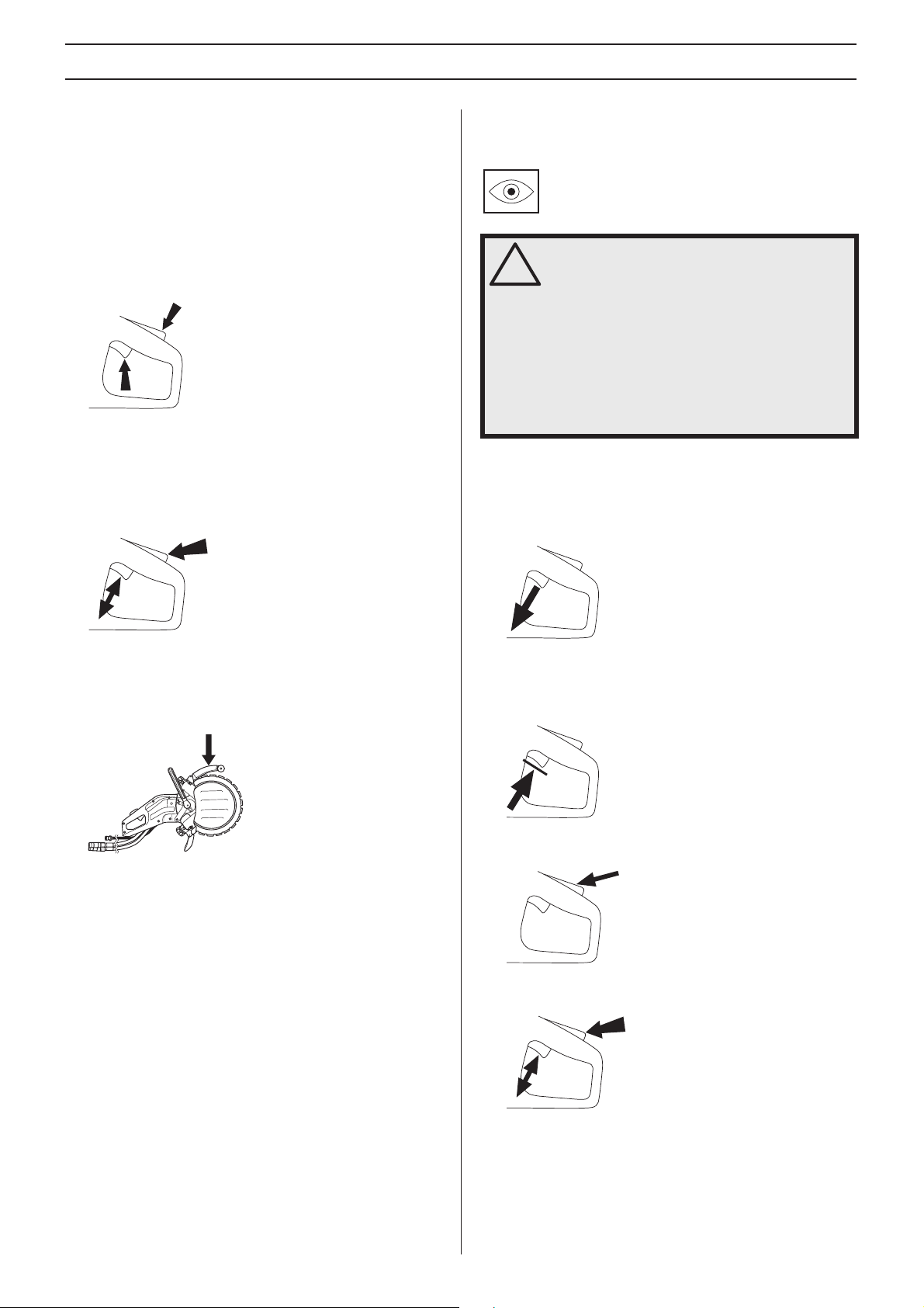
Switc h
The s witch is used to start and stop the machine.
English
– 5
Page 6
SAFETY INSTR UCTIONS
6
W
Switc h lock and ON/OFF valve for the water
The s witch lock is designed to prevent accidental operation of
the switch. The ON/OFF valve for the water supply is also
controlled with the switch lock.
When the switch lock (A) is pressed in this opens the water
valve and releases the switch (B).
As long as the switch is pressed in the switch lock remains
pressed in and the water valve open.
A
B
When you release your grip on the handle this resets both the
switch and the switch lock. This takes place via two
independent return spring systems. This position causes the
machine to stop and the switch to be locked.
The water valve returns to the stop position when the handle
is released.
Chec king, maintaining and servicing
′′
′′
the machine
ARNING! All servicing and repair work on
the machine requires special training. This is
!
especially true of the machine
equipment. If your machine fails any of the
checks described below you must contact
your service agent. When you buy any of our
products we guarantee the availability of
professional repairs and service. If the
retailer who sells your machine is not a
servicing dealer, ask him for the address of
your nearest service agent.
Chec king the starting and stopping functions of the switch
Star t the machine, release the switch, and check that the
machine and blade stop.
s safety equipment
′′
′′
s safety
Blade guar d
This guard is fi tted above the blade and is designed to prevent
parts of the blade or cutting fragments from being thrown
towards the user.
Chec king the switch lock
Chec k that the switch is locked when the switch lock is in its
home position.
Press the switch lock and check that it returns to its home
position when released.
Check that the switch and switch lock move freely and that
their return spring systems function.
–
Start the machine, release the switch, and check that the
machine and blade stop.
English
Page 7
SAFETY INSTR UCTIONS
•
T
Chec king the blade guard
WARNING! Always check that the guard is
correctly fitted before starting the machine.
!
Also check that the blade is fitted correctly
and is not damaged in anyway. A damaged
blade can cause personal injuries. See
instructions under the heading Assembly.
Chec k that the guard is complete and without any cracks or
deformations.
General saf ety precautions
A power cutter is designed to cut hard materials, such as
masonry. Observe the increased risk of kickback when
cutting soft materials. See instructions under the heading
How to avoid kickback.
• Do not use the power cutter until you have read the entire
contents of this Operator’s Manual.
All servicing, in addition to the points listed in the section
”Control, maintenance and service of the power cutter’s
safety equipment”, should be carried out by trained
service specialists.
• Never use the machine if you are tired, if you have drunk
alcohol, or if you are taking medication that could affect
your vision, your judgement or your co-ordination.
• Wear personal protective equipment. See instructions
under the heading Personal protective equipment.
• Never use a machine that has been modified in any way
from its original specification.
• Never use a machine that is faulty. Carry out the checks,
maintenance and service instructions described in this
manual. Some maintenance and service measures must
be carried out by trained and qualified specialists. See
instructions under the heading Maintenance.
• Never allow anyone else to use the machine without first
ensuring that they have understood the contents of the
operator’s manual.
ransport and storage
Do not store or tr ansport the power cutter with the blade fitted.
Store the power cutter in a lockable area so that it is out of
reach of children and unauthorised persons.
The blade should be removed from the machine after use and
stored well. Store the blade in the dry.
General w orking instructions
WARNING! This section describes basic
safety directions for using a power cutter.
!
This information is never a substitute for
professional skills and experience. If you get
into a situation where you feel unsafe, stop
and seek expert advice. Contact your dealer,
service agent or an experienced power
cutter user. Do not attempt any task that you
feel unsure of!
Basic safety rules
• Look around you:
- To ensure that people, animals or other things cannot affect
your control of the machine.
- To make sure that none of the above might come into
contact with the cutting equipment.
• Do not use the machine in bad weather, such as dense
fog, rain, strong wind, intense cold, etc. Working in bad
weather is tiring and can lead to dangerous conditions,
e.g. slippery surfaces.
• Never start to work with the power cutter before the
working area is clear and you have a firm foothold. Look
out for any obstacles with unexpected movement. Ensure
when cutting that no material can become loose and fall,
causing operating injury.Take great care when working on
sloping ground.
• Make sure that no clothes or parts of the body come in
contact with the cutting equipment when it is rotating.
• Keep at a safe distance from the cutting equipment when
it is rotating.
• The guard for the cutting equipment must always be on
when the machine is running.
• Ensure that the working area is sufficiently illuminated to
create a safe working environment.
• Do not move the machine when the cutting equipment is
rotating.
• Always ensure you have a safe and stable working
position.
• Make sure that no pipes or electrical cables are routed in
the area to be cut.
English
– 7
Page 8
SAFETY INSTRUCTIONS
Cutting
WARNING! The safety distance for the power
cutter is 15 metres. You are responsible to
!
ensure that animals and onlookers are not
within the working area. Do not start cutting
until the working area is clear and you are
standing firmly.
General
• Start cutting with the machine running at maximum
speed.
• Always hold the machine in a firm grip with both hands.
Hold it so that the thumbs and fingers grip round the
handles.
• Move the blade slowly backwards and forwards to give a
small contact surface between the blade and material to
be cut. This will mean the blade temperature is kept down
resulting in efficient cutting.
• Feed the machine in line with the blade. Side pressure can
destroy the blade and is extremely dangerous.
WARNING! Under all circumstances avoid
cutting with the side of the blade, as this will
!
definitely result in damage, breakage or can
cause serious injuries. Only use the cutting
section.
WARNING! Overexposure to vibration can
lead to circulatory damage or nerve damage
!
in people who have impaired circulation.
Contact your doctor if you experience
symptoms of overexposure to vibration.
These symptoms include numbness, loss of
feeling, tingling, pricking, pain, loss of
strength, changes in skin colour or
condition. These symptoms normally appear
in the fingers, hands or wrists.
Cutting technique
The technique described below is of a general character.
Check the details of each blade concerning individual cutting
characteristics.
• Support the work piece in such a way that it is possible to
predict what will happen, and so that the cut remains open
while cutting.
• Check that the blade is not in contact with anything when
the machine is started.
• Always cut at maximum speed.
• Start cutting gradually, let the machine work without
forcing or pressing the blade.
Do not pull the power cutter to one side, this
can cause the blade to jam or break
resulting in injury to people.
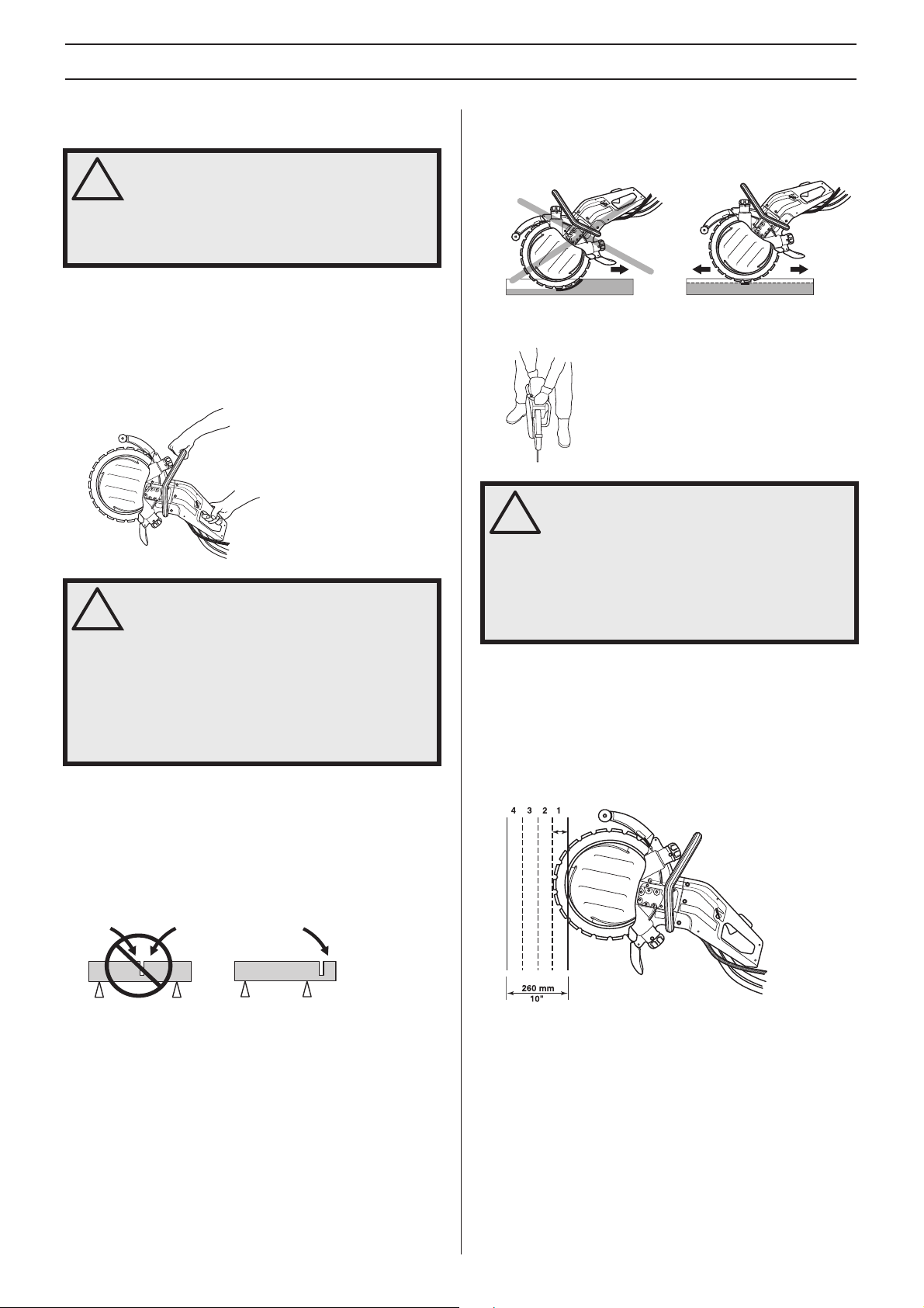
Cutting depth
K3600 MKII can cut up to a depth of 260 mm (10 inches).
Making a guide cut of 50-70 mm (2-3 inches) first, gives you
better control of the machine. This means the water disc can
penetrate into the workpiece and help control the machine.
Attempting to saw the entire depth in one run takes longer.
Working with several runs, 3 to 4 when the cut is 260 mm (10
inches) in depth, is much quicker.
8 – English
Page 9

SAFETY INSTRUCTIONS
Large work
Cuts exceeding 1 m - secure a batten along the line to be cut.
The batten acts as a guide. Use this guide to make a marking
cut along the entire length of the cut, 50-70 mm (2-3 inches)
in depth. Remove the guides once the marking cut has been
made.
Small work
First make a shallow marking cut, max 50-70 mm (2-3 inches)
in depth. Now make the final cut.
Cutting sequence
First make the lower horizontal cut. Now make the two vertical
cuts. Finish with the upper horizontal cut.
Remember to divide the blocks up into manageable pieces so
that they can be transported and lifted safely.
How to avoid kickback
WARNING! Kickback can happen very
suddenly and violently; kicking the power
!
cutter and cutting blade back at the user. If
this happens when the cutting blade is
moving it can cause very serious, even fatal
injuries. It is vital you understand what
causes kickback and that you can avoid it by
taking care and using the right working
technique.
What is kickback?
The word kickback is used to describe the sudden reaction
that causes the power cutter and cutting blade to be thrown
from an object when the upper quadrant of the blade, known
as the kickback zone, touches an object.
CAUTION! If the upper horizontal cut is made before the
lower horizontal cut, the work piece will fall on the blade and
jam it.
General rules
• Never start to cut with the upper quadrant of the blade as
shown in the figure, also known as the kickback zone.
• Always hold the machine in a firm grip with both hands.
Hold it so that the thumbs and fingers grip round the
handles.
• Keep a good balance and a firm foothold.
• Always cut at maximum speed.
• Stand at a comfortable distance from the work piece.
• Take care when inserting the blade in an existing cut.
• Never cut above shoulder height.
English – 9
Page 10

SAFETY INSTRUCTIONS
• Be alert to movement of the work piece or anything else
that can occur, which could cause the cut to close and
pinch the blade.
WARNING! Cutting plastics with a diamond
can cause kickback when the material
blade
!
melts due to the heat produced when cutting
and sticks to the blade.
Pull in
Pull in occurs when the disc’s lower section suddenly stops or
when the cut closes. (To avoid, see the heading ”Basic rules”
and ”Jamming/rotation”, here below.)
Pinching/rotation
If the cut is pressed together this can lead to jamming. The
machine can be pulled down suddenly with a very powerful
jerk.
How to avoid pinching
Support the work piece in such a way that the cut remains
open during the cutting operation and when the cut is
finished.
Sharpening diamond blades
Diamond blades can become dull when the wrong feeding
pressure is used or when cutting certain materials such as
heavily reinforced concrete. Working with a blunt diamond
blade causes overheating, which can result in the diamond
segments coming loose.
Sharpen the blade by cutting in a soft material such as
sandstone or brick.
Vibrations on diamond blades
The blade can become out of round and vibrate if a too high
feed pressure is used.
A lower feed pressure can stop the vibration. Otherwise
replace the blade. The blade shall be intended for the material
to be cut.
Diamond blades
Diamond blades consist of a steel body provided with
segments that contain industrial diamonds.
Always use a sharp diamond blade. Sharpen the blade by
cutting in a soft material such as sandstone or brick.
Diamond blades are available in several hardness classes. A
"soft" diamond blade has a relatively short service life and
large cutting capacity. It is used for hard materials such as
granite and hard concrete. A "hard" diamond blade has a
longer service life and reduced cutting capacity, and should
be used for soft materials such as brick and asphalt.
Diamond blades are ideal for masonry, reinforced concrete
and other composite materials. Diamond blades are not
recommended for cutting metal.
Water cooling
WARNING! Cool diamond blades
continuously with water to prevent
!
overheating that can cause the diamond
blade to break and pieces being thrown off
resulting in injury and damage.
Diamond blades should be sprinkled with water while cutting
to cool the blade and to bind dust that forms while cutting.
10 – English
Page 11

SETTINGS AND ADJUSTMENTS
Drive
On account of the machine’s unique design the driving power
is not transferred at the centre of the blade. The flanges on the
two guide rollers run in the blade’s grooves. Springs on the
guide rollers press out the rollers, which in turn press the Vshaped edge on the inside diameter of the blade against the
V-shaped groove in the drive wheel. The drive wheel is fitted
on an axle which is driven by the hydraulic motor.
This allows a total cutting depth of 260 mm (10 inches) with a
350 mm (14 inches) diamond blade.
1 Blade
2 Support rollers
3 Drive wheel
4 Guide rollers
5 V-shaped edge
Basic service
Fitting the blade
WARNING! Always disconnect the power
cutter from the hydraulic connection when
!
performing a service. Unexpected blade
movements can cause serious injuries.
We offers a number of blades for different materials in its
range. Check with your Husqvarna
are best suited for your usage.
WARNING! It is forbidden to reconstruct a
used blade. A used blade may be weakened.
!
A reconstructed blade can crack or break
into pieces and seriously injury the operator
or other persons.
WARNING! Check that the blade is not
damaged before fitting it on the machine.
!
Damaged blades can disintegrate and cause
serious personal injury.
dealer to see which blades
As the blade is used the inside diameter and the groove in the
drive wheel become worn.
The ring cutter will also work well in the future if:
• the drive wheel is not too worn
A) New
B) Worn
• the guide rollers are not too worn
A) New
B) Worn
• Wipe off any dirt from the surface of the blade.
• Loosen the locking nuts on the support roller cover.
• Unscrew the adjuster screws a few turns.
• adjustment between the rollers and blade is correct.
The roller setting should be checked twice during the life of
the diamond blade, once after fitting the blade and when the
blade is semi worn.
English – 11
Page 12

SETTINGS AND ADJUSTMENTS
• Loosen the knob to offload the springs.
• Pull out the lock for the front handle and move the handle
to the service position.
• Remove the three screws holding the support roller guard
using a 6 mm hex key and lift off the cover.
• Fit the support roller guard and ensure that the flanges on
the guide rollers still enter the blade’s grooves correctly.
Now tighten the three screws fully.
• Rotate the blade and make sure that the support rollers
are not clamped against the blade.
• Adjust the adjuster screws so that the support rollers
make contact against the blade.
• Fit the blade.
CAUTION! The blade has a groove (A) on one side that
acts a the guide groove for the support rollers. Ensure that
the V-shaped edge of the blade enters the drive wheel and
that the blade’s guide groove fits in the guide rollers. Also
see under the heading Drive.
• Press in the guide roller if necessary, so that it climbs into
the groove on the blade.
• Adjust so you can easily stop the support rollers using
your thumb when the blade is rotated. The support rollers
should only follow the blade occasionally.
• Tighten the locking nuts on the support roller guard.
• Rotate the blade and make sure you can still hold the
rollers with your thumb when the blade is rotated.
12 – English
Page 13

SETTINGS AND ADJUSTMENTS
CAUTION! The machine should be upright. If the machine
lies on its side the weight of the blade makes it difficult to
make a correct adjustment.
• Tighten the knobs fully and the machine is ready to use.
Hydraulic hoses
WARNING! The power cutter must not be
connected to a hydraulic pressure
!
exceeding 150 bar (3000 psi).
Water hose
Connect the water hose to the water supply. The water flow is
activated by opening the check valve. Minimum water flow: 4
l/min Note that the machine’s hose nipple is fitted with a filter.
Water supply
When you press in the switch lock (A) the water valve opens.
The water valve remains open and the switch lock (A) remains
pressed in as long as the switch (B) is held pressed in.
• Before connecting the hoses: Ensure that the couplings
are clean, both on the machine and the hoses.
• Connect the pressure hose (A) from the hydraulic system
to the female coupling on the machine.
• Connect the other hydraulic coupling (B) to the male
coupling. This hose leads oil back to the container.
CAUTION! Two hose kits can be connected when hose
lengths exceeding 18 m are required. Do not connect more
than two kits as the couplings cause large power loss. See the
Technical data.
Water dosage
The water flow can be adjusted during operations with your
thumb.
Ample water flow is needed for maximal blade life.
CAUTION! The water pressure and water flow is extremely
important for the blade’s cooling and service life. Inadequate
cooling shortens the life of the guide rollers, drive wheel and
the blade.
CAUTION! Make sure that the hoses can not be loosened
accidentally by turning the safety catches on the couplings to
the locked position before using the machine.
WARNING! When the machine is in operation
the hoses are under extreme pressure. Do
!
not try to connect or disconnect the hoses
when the hydraulic system is operational.
This can result in serious personal injuries.
English – 13
Page 14

STARTING AND STOPPING
Starting and stopping
WARNING! Note the following before
starting:
!
Make sure you are standing properly and
that the blade can not come into contact
with anything.
Keep people and animals well away from the
working area.
Check that the power source (the hydraulic
unit) supplies the correct oil flow and oil
pressure.
Starting
• Grip the front handle with the left hand.
• Grip the rear handle with the right hand. When you grip
the rear handle this releases the switch lock.
Stopping
The machine is stopped by releasing the switch.
14 – English
Page 15

MAINTENANCE
Maintenance
WARNING! Inspection and/or maintenance
should be carried out with the hydraulic
!
hoses disconnected.
Dismantling the complete guide roller
• Remove the support roller cover.
• Lift off the blade.
• The guide roller can now be pulled out of the chassis
Assembling the complete guide roller
• Screw the knob until it bottoms, and then loosen the knob
2 turns.
• Insert the guide roller in the chassis
• Unscrew the knob. First turn the knob a few turns until you
feel a resistance. The guide roller then follows the knob
out and stops when it feels a resistance.
The guide roller is pressed into the knob. In order to loosen
the guide roller, you need to continue turning the knob until it
loosens completely.
• Now press the guide roller into the knob.
Lubricate the guide roller’s sleeve using grease. Fit the
grease gun on the grease nipples (A) and pump in grease
until clean grease emerges from the overflow hole (B).
A
• Fit the blade. See the heading Fitting the blade.
B
Important notes:
• The support rollers do not drive the blade.
• Incorrect adjustment can result in damage to the blade.
• If the blade rotates slowly or stops, stop cutting
immediately and trouble shoot.
English – 15
Page 16

MAINTENANCE
Drive wheel
1 Lock the axle using the locking button. See the
instructions under the heading What is what?.
2 Loosen the centre screw and remove the washer.
3 You can now lift off the drive wheel.
CAUTION! Replace the drive wheel when fitting a new blade.
A worn drive wheel can result in the blade slipping and
becoming damaged.
Inadequate water flow drastically shortens the life of the drive
wheel.
Replacing the support rollers/guide rollers
B) Worn
• Replace the support rollers when the roller surface is flat,
(or) when the groove on the roller surface has worn away.
A) New
B) Worn
When worn rollers are replaced with new ones, you must
adjust the rollers against the blade. See the instructions under
the heading Settings and adjustments.
• Remove the support roller cover.
• Check the rollers for wear.
• Use a 19 mm spanner and 5 mm hex key to replace the
rollers.
Lubricate using bearing grease inside the rollers before the
new rollers are fitted.
• Replace the guide rollers when half of the flange on the
rollers is worn.
A) New
16 – English
Page 17

Reconstructing the blade
WARNING! Ring cutter blades must not be
reconstructed. Due to its design, a ring
!
cutter blade is exposed to other strains than
a centre driven 14 inch diamond blade.
Firstly, the drive wheel is driven on the inner
diameter of the blade so that both the
surfaces of the drive wheel and the blade are
exposed to wear. The core of the blade
becomes thinner and the guide wider, which
prevents the blade being driven by the
wheel. Secondly, the blade is exposed to
loads from the rollers and from the actual
cutting process when the blade is not held
completely straight. Strain builds up in the
blade until it cracks or breaks if it has been
reconstructed. A shattered blade can cause
serious personal injuries to the user or other
persons.
not approve ring cutting blades that have
been reconstructed. Contact your
Husqvarna dealer for instructions.
For this reason Husqvarna does
MAINTENANCE
Couplings
1 Water
2 Water filter
3 Return
4 Pressure
IMPORTANT! If the coupling is dirty, the dirt can enter the oil
and cause increased wear on the hydraulic motor, hydraulic
pump, valves, etc. It can also prevent the coupling from
sealing correctly.
Always clean the couplings before connecting to the hydraulic
system and the machine. Make sure the lock moves easily.
Clean the water filter if necessary.
Hydraulic hoses
Check the hydraulic hoses everyday before the machine is
used. Cracked, creased or weakened hoses must be
replaced.
English – 17
Page 18

MAINTENANCE
Maintenance schedule
CAUTION! The chart is based on daily use of the equipment.
Daily Twice a week
Support and guide rollers
Check the support rollers with regard to wear. X
Check the guide rollers with regard to wear. X
Lubricate the guide rollers. X
Hydraulic System
Inspect the hydraulic hoses. X
Inspect and clean the water nozzle. X
Drive system
Check the condition of the drive wheel. X
Water system
Inspect and clean the water nozzles on the water disc. X
Inspect the water adjustment control. X
Check the filter in the water coupling. X
Controls
Check that the controls work. X
Blade
Check the condition of the blade guard. X
Check the water disc. X
Blades conforming to EN13236
Husqvarna K3600 MKII only conforms to 98/37/EC and EN13236 together with the blades listed below:
Type Diameter, mm
Husqvarna
PXR XX 350
ELR XX (5,6 / ,220) 350
SLR XX 350
R550-0355 (5,6 mm) 350
R530-0355 350
R510-0355 (5,6 mm) 350
Note: The blades are available in different hardnesses for different materials, this is stated with two digits, XX.
18 – English
Page 19

TROUBLE SHOOTING
Mechanics
Symptom Probable cause
The blade does not rotate. Roller knobs not tightened fully.
The blade not fitted on guide rollers correctly.
Rollers tensioned too much.
Possible faulty hose connection to the hydraulic system.
Possible faulty hose connection to the drive source or other hydraulic problem.
The blade rotates too slowly. Roller knobs not tightened fully.
Worn drive wheel.
The V-shaped inner diameter of the blade is worn.
The springs on the guide rollers are weakened.
Dirty overpressure valve in the hydraulic system.
Valve knob on the hydraulic motor does not move the correct distance.
Defective roller bearings.
Inadequate oil flow, check the hydraulic oil flow.
The blade jumps out of its position. Roller setting too loose.
Worn guide rollers.
The blade not fitted on guide rollers correctly.
Damaged blade.
The blade warps. Rollers tensioned too much.
Blade overheating.
Segments break. Bent, twisted or badly maintained blade.
The blade cuts too slowly. Wrong blade for the material in question.
Check that the right amount of water reaches the blade.
The blade slips.
The guide rollers does not move in and out freely. A seized roller can not press the blade hard
enough against the drive wheel.
Worn drive wheel. Abrasive material and too little water when cutting increases the wear on
the wheel.
Worn guide roller flange. When more than half of the width of the flange is worn the blade
slips.
The blade’s groove and inner edge are worn. Caused by inferior flushing of abrasive material
and/or a worn drive wheel causing the blade to slip.
English – 19
Page 20

TECHNICAL DATA
Technical data K3600 MKII
Blade diameter, mm/inches 350/14”
Cutting depth, mm/inches 260/10”
Max. peripheral speed, m/s / r/min 55/3000
Max.motor speed, r/min 17000
Hydraulic motor Geared motor (open centre valve)
Max. hydraulic pressure, bar/ (psi) 150 / 2200
Oil flow, min-max, l/min 35-42
Height, mm/inches 410
Length, mm/inches 715
Width, mm/inches 260
Weight, excl. blade, kg 8,3
Weight ring blade, kg 0,8
Specifications hydraulic oil* 150 VG 32 (10W)**
Oil temperature (operational), °C 60
Water consumption, l/min 4
Hydraulic couplings 1/2' FF according to HTMA regulations. (thread 3/8')
*We recommend the use of environmentally approved hydraulic oil.
**With high ambient temperatures use oil with a higher viscosity.
Noise emissions
(see note 1)
Sound power level, measured dB(A) 110
Sound power level, guaranteed LWA dB(A) 111
Sound levels
Equivalent sound pressure level at the operator’s ear,
according to ISO/DIS 15744 and ISO/DIS 11201, dB (A)
Vibration levels
Handle vibrations measured according to ISO/DIS 8662-4
Front handle, m/s
Rear handle, m/s
Note 1: Noise emissions in the environment measured as sound power (LWA) in conformity with EC directive 2000/14/EC.
2
2
99
4,3
6,0
Extending the hydraulic hoses
When extending the hydraulic hoses, the inside diameter of the hose must be increased according to the table to counteract power
loss.
Extension, m
Up to 30 m 1/2
30-45 5/8
45-100 3/4
Inside diameter of the hydraulic
hose, inches
20 – English
Page 21

TECHNICAL DATA
EC-declaration of conformity
Husqvarna Construction Products, SE-433 81 Partille, Sweden, tel: +46-31-949000, declares under sole responsibility that the
power cutter Husqvarna K3600 from 2006’s serial numbers and onwards (the year is clearly stated in plain text on the rating plate
with subsequent serial number), complies with the requirements of the COUNCIL’S DIRECTIVES:
- of June 22, 1998 ”relating to machinery” 98/37/EC, annex IIA.
- of May 8, 2000 ”relating to the noise emissions in the environment” 2000/14/EC.
The following harmonised standards have been applied: ISO/DIS 15744, ISO/DIS 11201.
SMP Svensk Maskinprovning AB, Fyrisborgsgatan 3, SE-754 50 Uppsala, Sweden, has carried out voluntary type approval for
Husqvarna AB.
The certificate has the number: 01/169/010 – K3600 MKII.
Partille January 3, 2006
Ove Donnerdal, Development Manager
English – 21
Page 22

´®z+R=J¶6G¨
´®z+R=J¶6G¨
Page 23

Page 24

´®z+R=J¶6G¨
1150294-26
´®z+R=J¶6G¨
2006-12-15
 Loading...