


Operator’s manual, Manuel d’utilisation
Manual de instrucctiones,Bedienungsanweisung
Istruzioni per l’uso,
操作手册
K 1270R
Please read the operator’s manual carefully and make sure you understand the instructions before using the machine.
Lea detenidamente el manual de instrucciones y asegúrese de entender su contenido antes de utilizar la máquina.
Lesen Sie die Bedienungsanweisung sorgfältig durch und machen Sie sich mit dem Inhalt vertraut, bevor Sie das Gerät benutzen.
Prima di usare la macchina, leggere per intero le istruzioni per l’uso e accertarsi di averne compreso il contenuto.
Lire attentivement et bien assimiler le manuel d’utilisation avant d’utiliser la machine.
请认真阅读本操作手册,确保在充分理解各项说明之后再使用机器。
EN FR ES DE IT CN
!
!
2
W
W
W
CA
NO
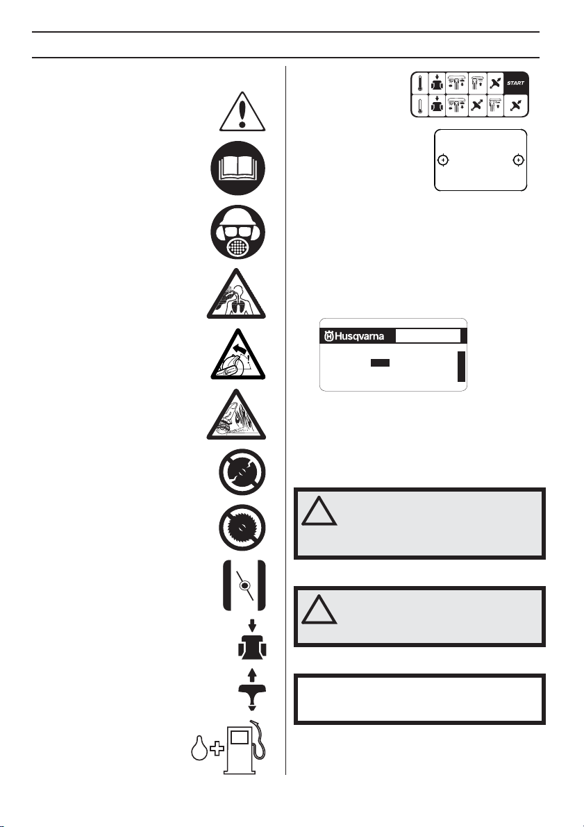
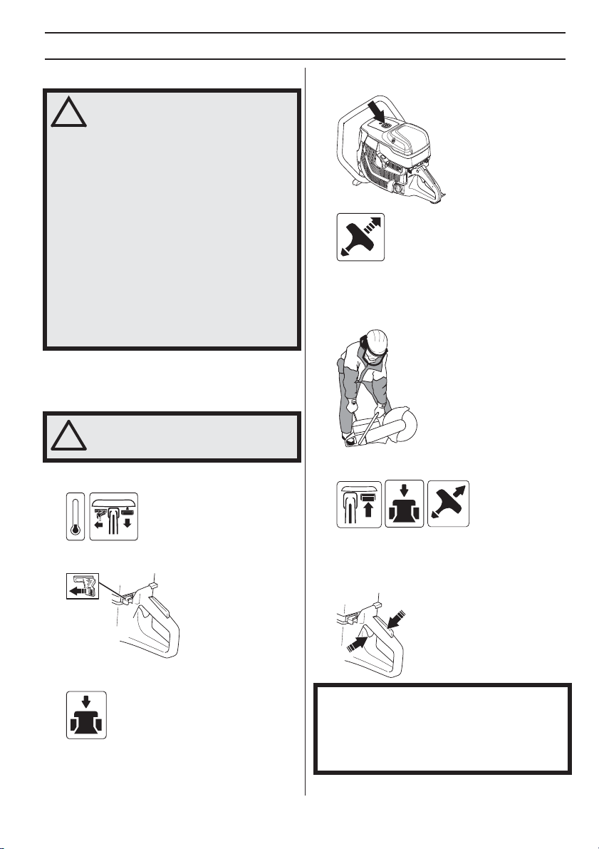
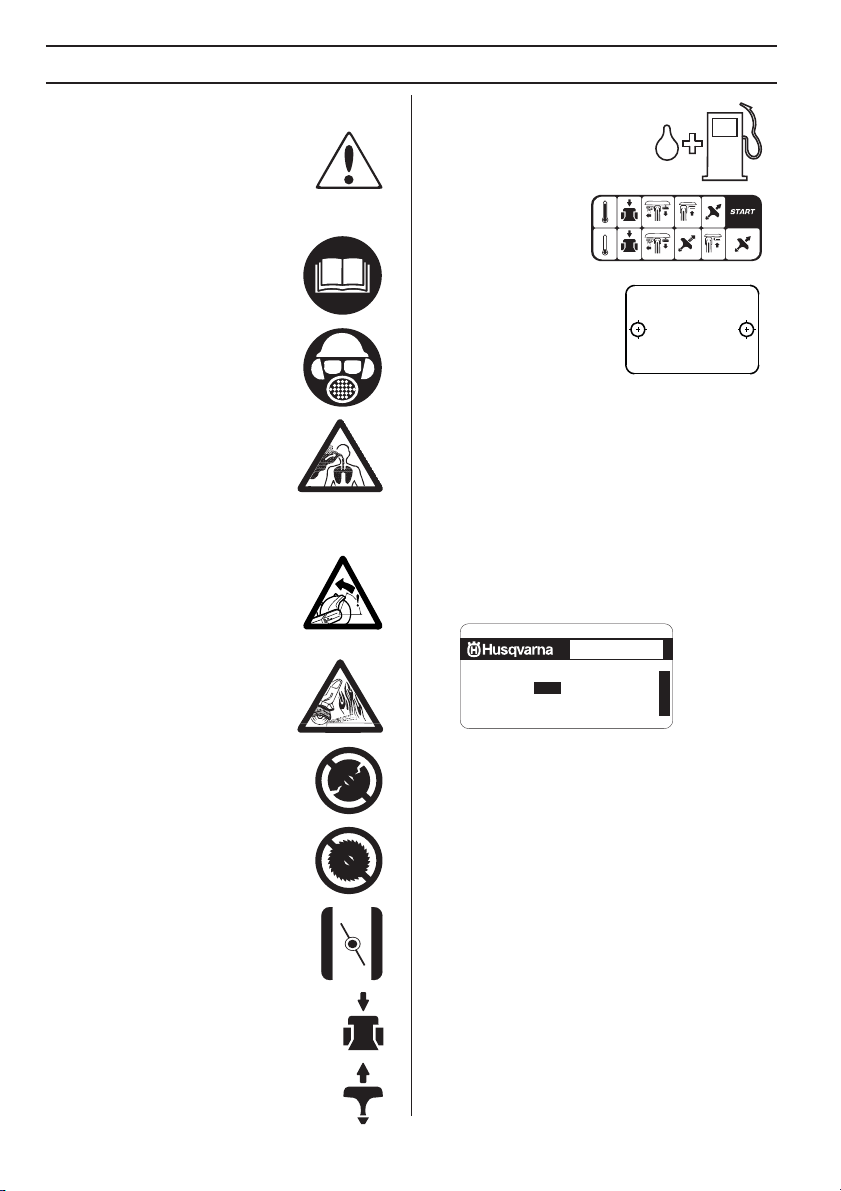
Symbols on the mac hine
ARNING! The machine can be a
dangerous tool if used incorrectly or
carelessly, which can cause serious or
fatal injury to the operator or others.
Please read the operator’s manual
carefully and make sure you
understand the instructions before
using the machine.
Wear personal protective equipment.
See instructions under the ”Personal
protective equipment” heading.
WARNING! Dust forms when cutting,
this can cause injuries if inhaled. Use
an approved breathing mask. Avoid
inhaling exhaust fumes. Always
provide for good ventilation.
WARNING! Kickbacks can be sudden,
rapid and violent and can cause life
threatening injuries. Read and
understand the instructions in the
manual before using the machine.
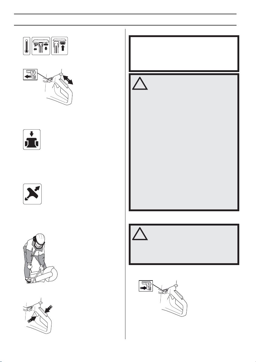
WARNING! Sparks from the cutting
blade can cause fire in combustible
materials such as: petrol (gas), wood,
dry grass etc.
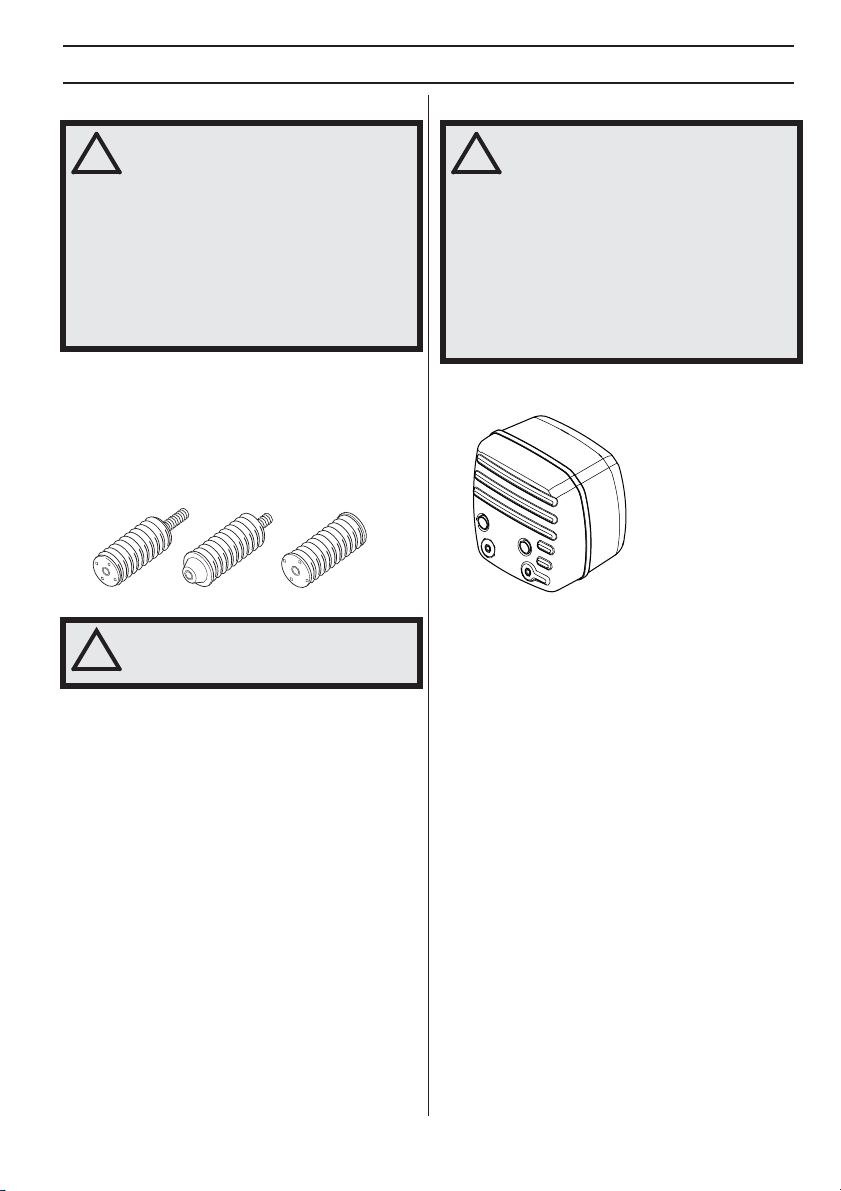
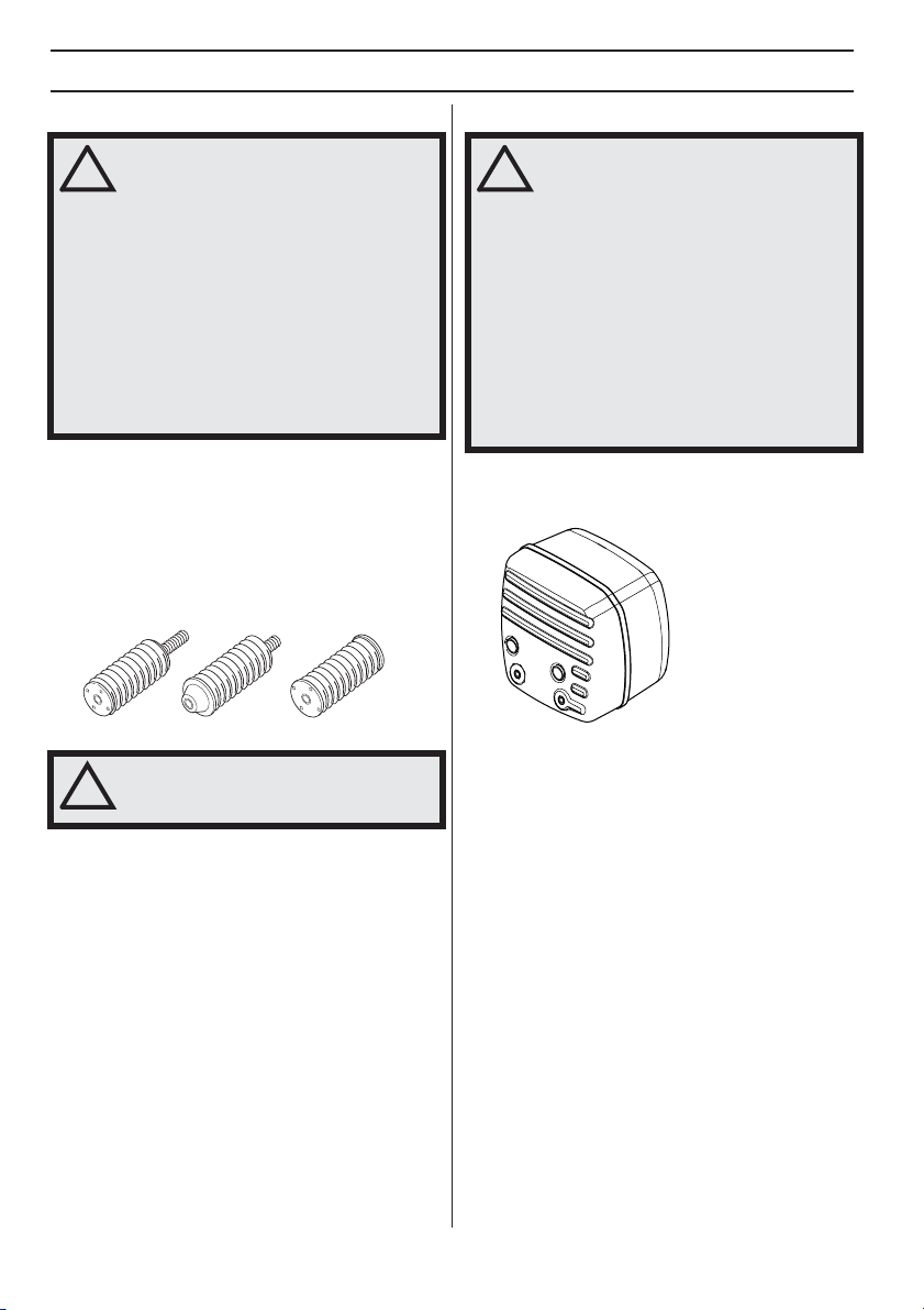
Ensure the blades are not cracked or
damaged in any other way.
KEY T O SYMBOLS
Starting instruction
decal See instructions
under the heading
Starting and stopping.
Type plate
Row 1: Brand, Model (X,Y)
Row 2: Serial No. with
manufacturing date (y, W, X):
Year, Week, Sequence No.
Row 3: Product No. (X)
Row 4: Manufacturer
Row 5: Manufacturer address
Row 6-7: If applicable, EC typ-approval (X, Y): Approval
code, Approval stage
The Emissions Compliance Period referred to on the
Emission Compliance label indicates the number of
operating hours for which the engine has been shown to
meet Federal and Californian emissions requirements.
EMISSION CONTROL INFORMATION
HUSQVARNA AB, HUSKVARNA, MADE IN SWEDEN
THIS ENGINE MEETS U.S. EPA EXH/EVP
REGS FOR 2016 SORE. REFER TO
OPERATOR’S MANUAL FOR MAINTENANCE
SPECIFICATIONS AND ADJUSTMENTS.
EMISSIONS COMPLIANCE PERIOD: 300 HRS
Other symbols/decals on the mac hine refer to special
certification requirements for certain markets.
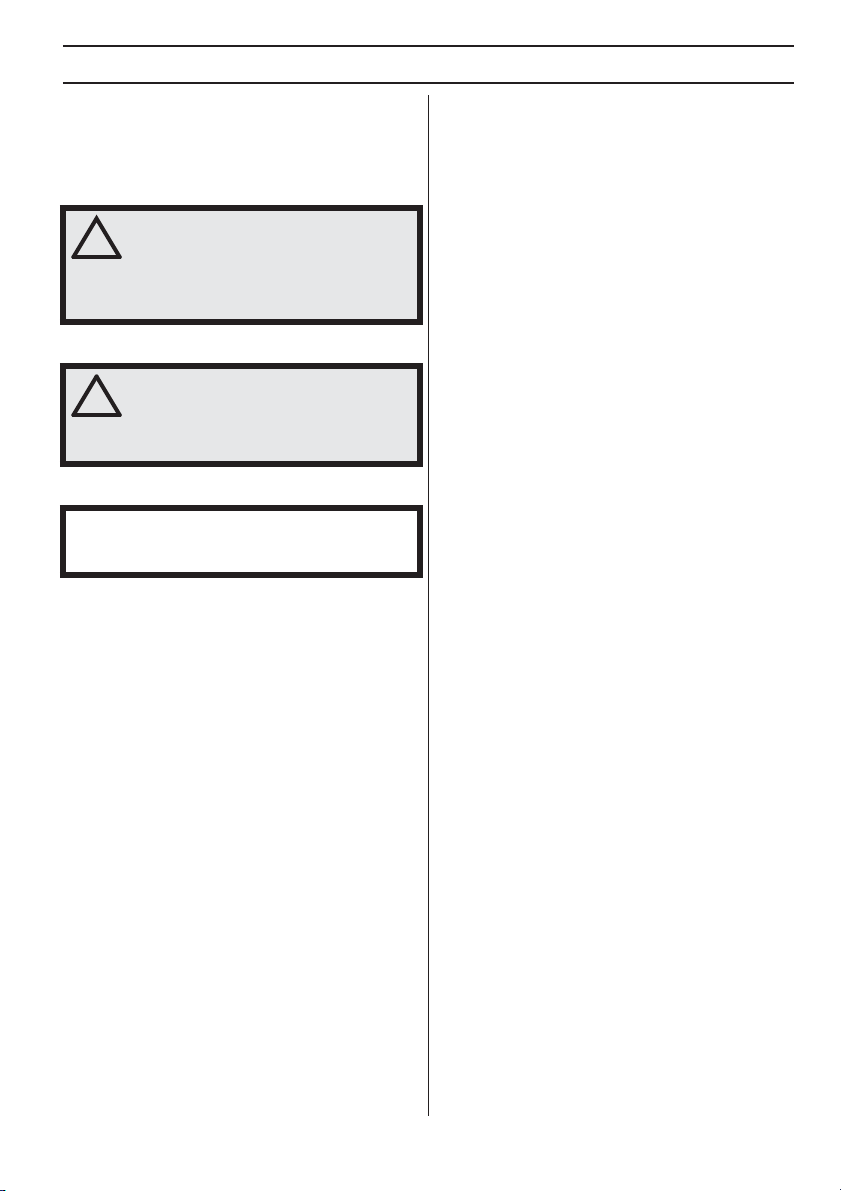
Explanation of warning le vels
The w arnings are graded in three levels.
ARNING!
2016
XXXXXXXXX YYYY
s / n YYYY WWXXXXX
XXX XX XX-XX
Husqvarna AB
Huskvarna, SWEDEN
XXXXXXXXXXX
XXXXXXXXXXXX (YY)
®
EM/N74ccB0
30-5
43
6
105
Do not use circular saw blades
Choke.
Decompression valve
Starter handle
Refuelling, petrol/oil mix
– English
ARNING! Used if there is a risk of
serious injury or death for the operator
or damage to the surroundings if the
instructions in the manual are not
followed.
CAUTION!
UTION! Used if there is a risk of injury
to the operator or damage to the
surroundings if the instructions in the
manual are not followed.
NOTICE!
TICE! Used if there is a risk of damage to materials
or the machine if the instructions in the manual are not
followed.
u
t
h
m
MA
ST
TR
T
T
Y
CONTENTS
Contents
KEY TO SYMBOLS
Symbols on the machine ...................................... 2
Explanation of warning levels ............................... 2
CONTENTS
Contents ............................................................... 3
Note the following before starting: ........................ 3
PRESENT ATION
Dear Customer , .................................................... 4
Design and features ............................................. 4
WHA T IS WHAT?
What is what on the machine? ............................. 5
CHINE´S SAFETY EQUIPMENT
Gener al ................................................................. 6
OPERA TING
Protectiv e equipment ............................................ 8
FUEL HANDLING
Gener al ................................................................. 9
Fuel ...................................................................... 9
Fueling .................................................................. 10
Transport and storage .......................................... 10
ARTING AND STOPPING
Bef ore starting ...................................................... 11
Starting ................................................................. 11
Stopping ............................................................... 12
MAINTENANCE
Gener al ................................................................. 13
Maintenance schedule ......................................... 13
Cleaning ............................................................... 13
Functional inspection ............................................ 14
OUBLESHOOTING
roubleshooting schedule ..................................... 17
TECHNICAL D ATA
echnical data ...................................................... 18
Declaration of conformity of partly completed
machinery .............................................................
FEDERAL EMISSION CONTR OL WARRANTY
STATEMENT
OUR WARRANTY RIGHTS AND OBLIGATIONS 20
Note the f ollowing before starting:
The engine exhaust from this prod
contains chemicals known to the S
of California to cause cancer, birt
defects or other reproductive har
NOTICE! CALIFORNIA AIR RESOURCES BOARD
(CARB):
This machine is considered a preempt OffRoad Applicatoin as relating to CARB standards. The
U.S. EPA has sole authority to establish emission
standards for preempt construction equipment. For
more information see www.arb.ca.gov/msprog/offroad/
preempt.htm
19
English
–
3

4
PRESENT A TION
Dear Customer ,
Thank y ou for choosing a Husqvarna product!
It is our wish that you will be satisfied with your product
and that it will be your companion for a long time. A
purchase of one of our products gives you access to
professional help with repairs and services. If the retailer
who sells your machine is not one of our authorized
dealers, ask him for the address of your nearest service
workshop.
This operator’s manual is a valuable document. Make
sure it is always at hand at the work place. By following its
content (operating, service, maintenance etc.) the life
span and the second-hand value of the machine can be
extended. If you will sell this machine, make sure that the
buyer will get the operator´s manual.
More than 300 y ears of innovation
Husqv arna AB is a Swedish company based on a tradition
that dates back to 1689, when the Swedish King Karl XI
ordered the construction of a factory for production of
muskets. At that time, the foundation was already laid for
the engineering skills behind the development of some of
the world's leading products in areas such as hunting
weapons, bicycles, motorcycles, domestic appliances,
sewing machines and outdoor products.
Husqvarna is the global leader in outdoor power products
for forestry, park maintenance and lawn and garden care,
as well as cutting equipment and diamond tools for the
construction and stone industries.
Owner responsibility
It is the o wner’s/employer’s responsibility that the operator
has sufficient knowledge about how to use the machine
safely. Supervisors and operators must have read and
understood the Operator’s Manual. They must be aware
of:
• The machine’s safety instructions.
• The machine’s range of applications and limitations.
• How the machine is to be used and maintained.
National legislation could regulate the use of this
machine. Find out what legislation is applicable in the
place where you work before you start using the machine.
Local regulations could restrict the use of this machine.
Find out what regulations are applicable where you work
before you start using the machine.
The man ufacturer’s reservation
Subsequent to pub lishing this manual Husqvarna may
issue additional information for safe operation of this
product. It is the owner’s obligation to keep up with the
safest methods of operation.
Husqvarna AB has a policy of continuous product
development and therefore reserves the right to modify
the design and appearance of products without prior
notice.
For customer information and assistance, contact us at
our website: www.husqvarna.com
– English
Design and f eatures
This po wer unit is a partly completed machinery, intended
for OEM design of a hand held high speed power cutter.
Some of the unique features of your product are
described below.
Active Air Filtration™
Centr ifugal air cleaning for longer service life and longer
service intervals.
Smar tCarb™
Built-in automatic fi lter compensation maintains high
power and reduces fuel consumption.
X-T orq®
The X-T orq® engine provides a more accessible torque
for a wider range of speeds which results in maximum
cutting capacity. X-Torq® reduces the fuel consumption
by up to 20% and the emissions by up to 60%.
EasyStar t
The engine and star ter are designed to ensure quick and
easy starting of the machine. Reduces the pull resistance
in the starter cord by up to 40%. (Reduces the
compression during starting.)
Effi cient vibration damping system
Effi cient vibration dampers spare arms and hands.
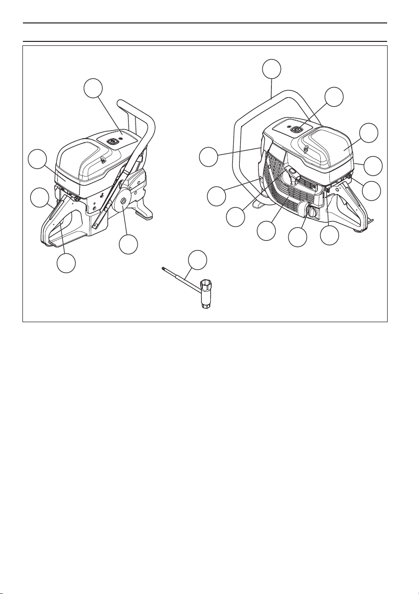
WHA T IS WHA T?
1
1
16
15
14
12
13
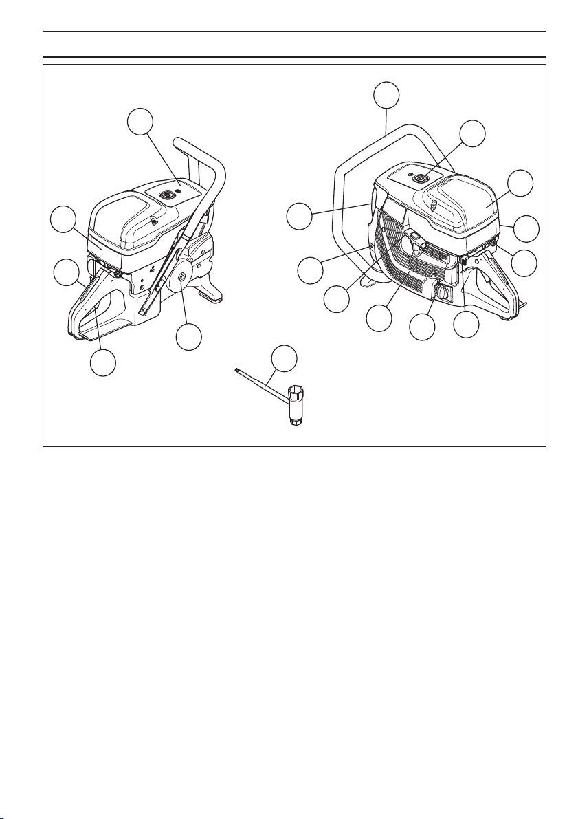
What is what on the mac hine?
Front handle
2 Decompression valve
3 Air filter cover
4 Cylinder cover
5 Choke control with start throttle lock
6 Stop switch
7 Fuel cap
8 Starter housing
9 Starter handle
11
10
9
8
17
10 Type plate
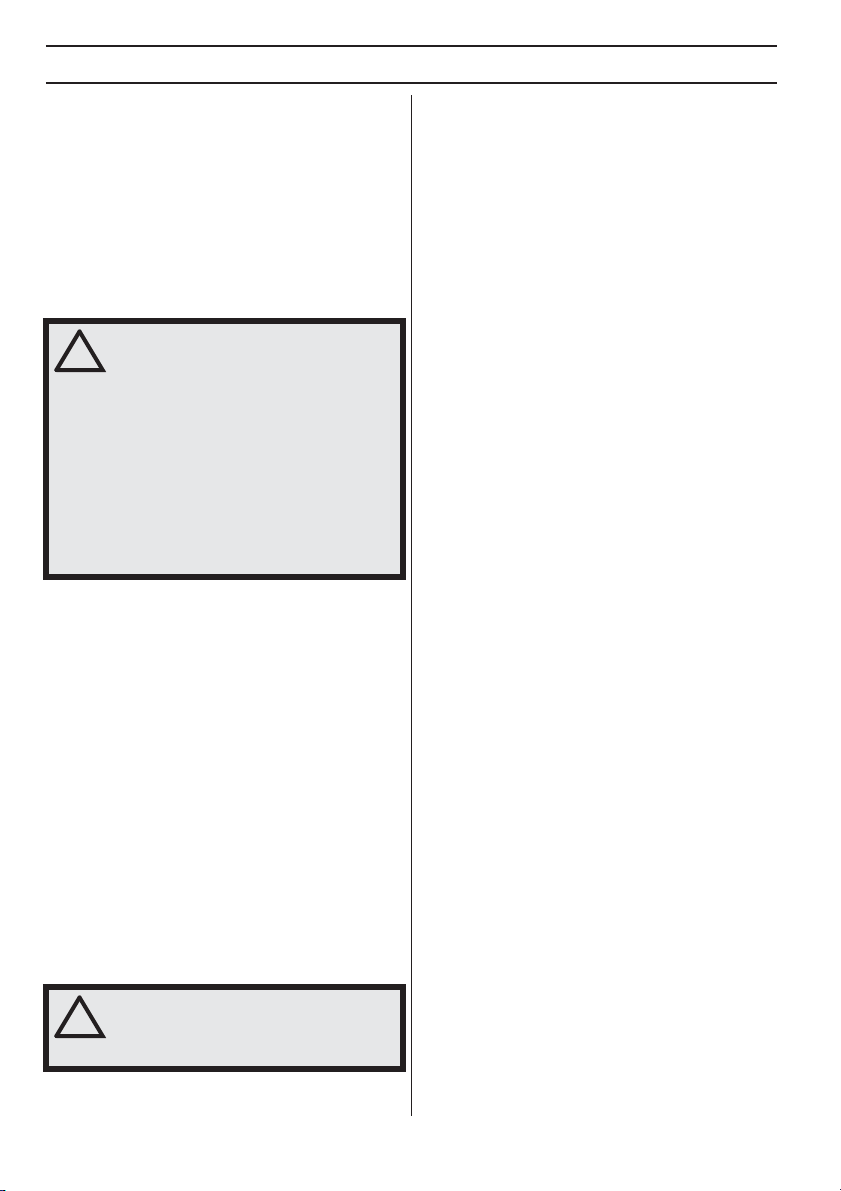
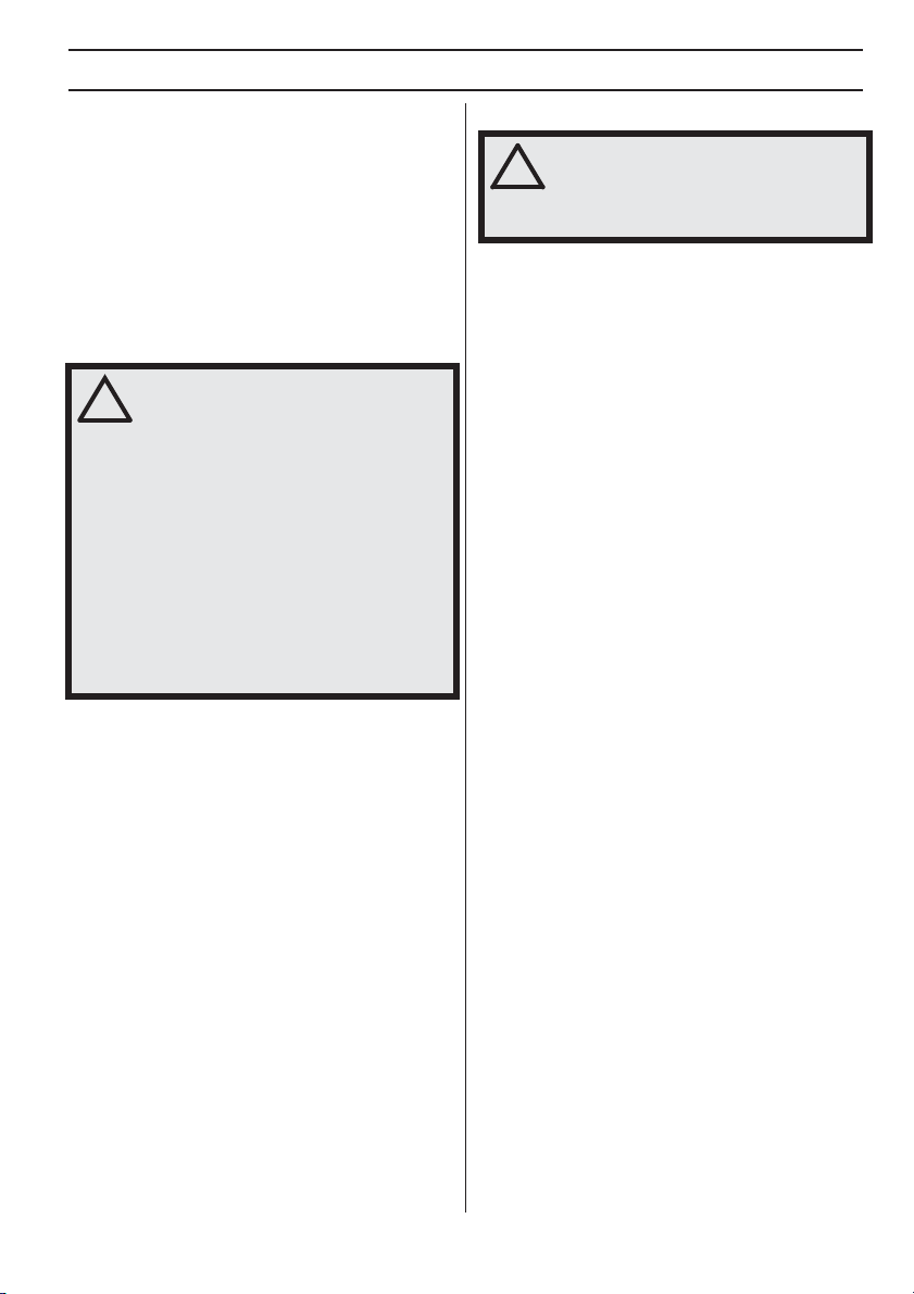
11 Muffler
12 Drive gear and clutch
13 Throttle trigger
14 Throttle trigger lockout
15 Starting instruction decal
16 Information and warning decal
17 Combination spanner, torx
2
3
4
5
7
6
English – 5
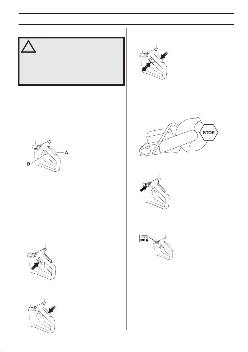
CHINE´S SAFETY EQ UIPMENT
General
ARNING! Never use a machine that has
faulty safety equipment! If your machine
!
fails any checks contact your service
agent to get it repaired.
The engine should be switched off, and
the stop switch in STOP position.
This section descr ibes the machine´s safety equipment,
its purpose, and how checks and maintenance should be
carried out to ensure that it operates correctly.
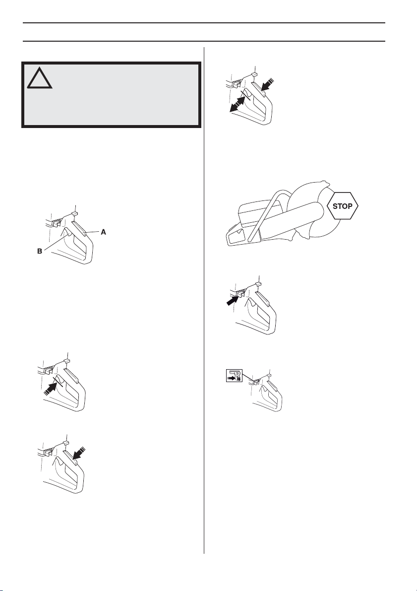
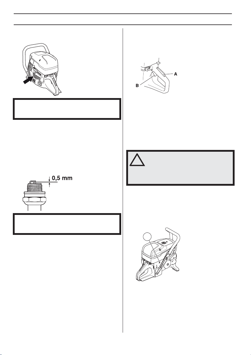
Thr ottle trigger lockout
The throttle tr igger lock is designed to prevent accidental
operation of the throttle. When the lock (A) is pressed in
this releases the throttle (B).
The trigger lock remains pressed in as long as the throttle
is pressed. When the grip on the handle is released the
throttle trigger and the throttle trigger lock both return to
their original positions. This is controlled by two
independent return spring systems. This means that the
throttle trigger is automatically locked in the idle position.
Chec king the throttle lockout
Make sure the throttle control is locked at the idle
setting when the throttle lockout is released.
MA
6
•
• Check that the throttle trigger and throttle lockout
move freely and that the return springs work properly.
• Start the power cutter and apply full throttle. Release
the throttle control and check that the cutting blade
stops and remains stationary. If the cutting blade
rotates when the throttle is in the idle position you
should check the carburettor’s idle adjustment. See
instructions in the section "Maintenance".
Stop s witch
Use the stop s witch to switch off the engine.
Chec king the stop switch
Start the engine and make sure the engine stops
when you move the stop switch to the stop setting.
•
W
• Press the throttle lockout and make sure it returns to
its original position when you release it.
– English
Vibration damping system
!
CHINE´S SAFETY EQ UIPMENT
Muffler
MA
•
WARNING! Overexposure to vibration
can lead to circulatory damage or nerve
!
damage in people who have impaired
circulation. Contact your doctor if you
experience symptoms of overexposure
to vibration. Such symptoms include
numbness, loss of feeling, tingling,
pricking, pain, loss of strength, changes
in skin colour or condition. These
symptoms normally appear in the
fingers, hands or wrists. These
symptoms may be increased in cold
temperatures.
Your machine is equipped with a vibration damping
system that is designed to minimize vibration and
make operation easier.
• The machine ′ s vibration damping system reduces the
transfer of vibration between the engine unit/cutting
equipment and the machine
body, including the cutting equipment, is insulated
from the handles by vibration damping units.
Checking the vibration damping system
WARNING! The engine should be
switched off, and the stop switch in
!
STOP position.
• Check the vibration damping units regularly for cracks
or deformation. Replace them if damaged.
• Check that the vibration damping element is securely
attached between the engine unit and handle unit.
′s handle unit. The engine
WARNING! Never use a machine without
a muffler, or with a faulty muffler. A
damaged muffler may substantially
increase the noise level and the fire
hazard. Keep fire fighting equipment
handy.
The muffler gets very hot during and
after use as well as when idling. Be
aware of the fire hazard, especially when
working near flammable substances and/
or vapours.
Keep fire fighting equipment handy.
The muffler is designed to keep noise levels to a minimum
and to direct exhaust fumes away from the user.
Inspecting the muffler
Check regularly that the muffler is complete and secured
correctly.
English
–
7
OPERATING
Protective equipment
General
Do not use the machine unless you are able to call for
help in the event of an accident.
Personal protective equipment
You must use approved personal protective equipment
whenever you use the machine. Personal protective
equipment cannot eliminate the risk of injury but it will
reduce the degree of injury if an accident does happen.
Ask your dealer for help in choosing the right equipment.
WARNING! The use of products such as
cutters, grinders, drills, that sand or form
!
material can generate dust and vapours
which may contain hazardous chemicals.
Check the nature of the material you
intend to process and use an appropriate
breathing mask.
Long-term exposure to noise can result
in permanent hearing impairment. So
always use approved hearing protection.
Listen out for warning signals or shouts
when you are wearing hearing
protection. Always remove your hearing
protection as soon as the engine stops.
Always wear:
• Approved protective helmet
• Hearing protection
• Approved eye protection. If you use a face shield then
you must also wear approved protective goggles.
Approved protective goggles must comply with
standard ANSI Z87.1 in the USA or EN 166 in EU
countries. Visors must comply with standard EN 1731.
• Breathing mask
• Heavy-duty, firm grip gloves.
• Tight-fitting, heavy-duty and comfortable clothing that
permits full freedom of movement. Cutting generates
sparks that can ignite clothing. Husqvarna
recommends that you wear flame-retardant cotton or
heavy denim. Do not wear clothing made of material
such as nylon, polyester or rayon. If ignited such
material can melt and cling to the skin. Do not wear
shorts
• Boots with steel toe-caps and non-slip sole.
Other protective equipment
CAUTION! Sparks may appear and start a
fire when you work with the machine.
!
Always keep fire fighting equipment
handy.
• Fire Extinguisher
• First aid kit
8 – English
FUEL HANDLING
General
WARNING! Running an engine in a
confined or badly ventilated area can
!
result in death due to asphyxiation or
carbon monoxide poisoning. Use fans to
ensure proper air circulation when
working in trenches or ditches deeper
than one meter.
Fuel and fuel fumes are flammable and
can cause serious injury when inhaled or
allowed to come in contact with the skin.
For this reason observe caution when
handling fuel and make sure there is
adequate ventilation.
The exhaust fumes from the engine are
hot and may contain sparks which can
start a fire. Never start the machine
indoors or near combustible material!
Do not smoke and do not place any hot
objects in the vicinity of fuel.
Fuel
NOTICE! The machine is equipped with a two-stroke
engine and must always be run using a mixture of petrol
and two-stroke oil. It is important to accurately measure
the amount of oil to be mixed to ensure that the correct
mixture is obtained. When mixing small amounts of fuel,
even small inaccuracies can drastically affect the ratio of
the mixture.
Petrol
• Use good quality unleaded or leaded petrol.
• The lowest octane recommended is 90 (RON). If you
run the engine on a lower octane grade than 90 socalled knocking can occur. This gives rise to a high
engine temperature, which can result in serious
engine damage.
• When working at continuous high revs a higher octane
rating is recommended.
Environment fuel
HUSQVARNA recommends the use of alkylate fuel,
either Aspen two-stroke fuel or environmental fuel for
four-stroke engines blended with two-stroke oil as set out
below. Note that carburettor adjustment may be
necessary when changing the type of fuel (see the
instructions under the heading Carburettor).
Ethanol blended fuel, E10 may be used (max 10%
ethanol blend). Using ethanol blends higher than E10 will
create lean running condition which can cause engine
damage.
Two-stroke oil
• For best results and performance use HUSQVARNA
two-stroke engine oil, which is specially formulated for
our air-cooled two-stroke engines.
• Never use two-stroke oil intended for water-cooled
engines, sometimes referred to as outboard oil (rated
TCW).
• Never use oil intended for four-stroke engines.
Mixing
• Always mix the petrol and oil in a clean container
intended for fuel.
• Always start by filling half the amount of the petrol to
be used. Then add the entire amount of oil. Mix
(shake) the fuel mixture. Add the remaining amount of
petrol.
• Mix (shake) the fuel mixture thoroughly before filling
the machine’s fuel tank.
• Do not mix more than one month’s supply of fuel at a
time.
Mixing ratio
• 1:50 (2%) with HUSQVARNA two-stroke oil or
equivalent.
Petrol, litre Two-stroke oil, litre
2% (1:50)
5 0,10
10 0,20
15 0,30
20 0,40
• 1:33 (3%) with oils class JASO FB or ISO EGB
formulated for air-cooled, two-stroke engines or mix
as per recommendation from the oil manufacturer.
English – 9
Fueling
!
FUEL HANDLING
WARNING! Taking the following
precautions, will lessen the risk of fire:
Do not smoke and do not place any hot
objects in the vicinity of fuel.
Always stop the engine and let it cool for
a few minutes before refuelling. The
engine should be switched off, and the
stop switch in STOP position.
When refuelling, open the fuel cap slowly
so that any excess pressure is released
gently.
Clean the area around the fuel cap.
Tighten the fuel cap carefully after
refuelling.
If the cap is not properly tightened the
cap might vibrate lose and fuel may
escape from the fuel tank creating a fire
hazard.
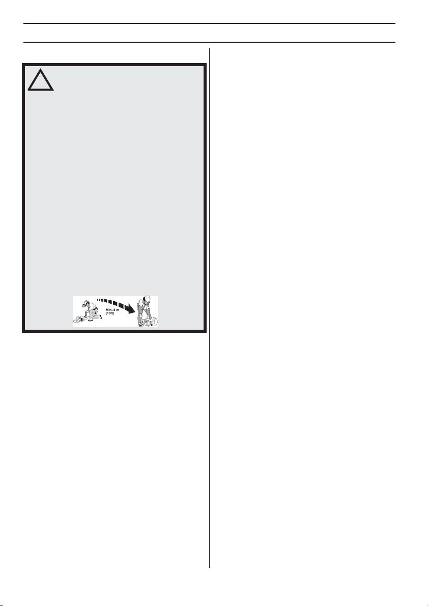
Move the machine at least 3 m from the
refuelling point before starting it.
Never start the machine:
• If you have spilled fuel or engine oil on the machine.
Wipe off the spill and allow the remaining fuel to
evaporate.
• If you have spilled fuel on yourself or your clothes,
change your clothes. Wash any part of your body that
has come in contact with fuel. Use soap and water.
• If the machine is leaking fuel. Check regularly for
leaks from the fuel cap and fuel lines.
• Unless the fuel cap is securely tightened after
refueling.
Transport and storage
• Store and transport the machine and fuel so that there
is no risk of any leakage or fumes coming into contact
with sparks or open flames, for example, from
electrical machinery, electric motors, electrical relays/
switches or boilers.
• When storing and transporting fuel always use
approved containers intended for this purpose.
Long-term storage
• When storing the machine for long periods the fuel
tank must be emptied. Contact your local petrol
station to find out where to dispose of excess fuel.
10 – English
STARTING AND STOPPING
Before starting
WARNING! Note the following before
starting: Please read the operator’s
!
manual carefully and make sure you
understand the instructions before using
the machine.
Wear personal protective equipment. See
under heading ”Personal protective
equipment”.
Do not start the machine without the belt
and belt guard fitted. Otherwise the
clutch could come loose and cause
personal injuries.
Check that the fuel cap is properly
secured, and that there is no fuel
leakage.
Make sure no unauthorised persons are
in the working area, otherwise there is a
risk of serious personal injury.
• Perform daily maintenance. See instructions in the
section "Maintenance".
Starting
WARNING! The cutting blade rotates
when the engine is started. Make sure it
!
can rotate freely.
With a cold engine:
automatically returns to its initial position when the
machine starts.
• Grip the front handle with your left hand. Put your right
foot on the lower section of the rear handle pressing
the machine against the ground. Pull the starter
handle with your right hand until the engine starts.
Never twist the starter cord around your hand.
• The machine stops when the engine fires because the
choke control is pulled out.
• Make sure that the stop switch (STOP) is in the left
position.
• Start throttle position and choke is obtained by pulling
out the choke control completely.
• Decompression valve: Press in the valve to reduce
the pressure in the cylinder, this is to assist starting
the power cutter. The decompression valve should
always be used when starting. The valve
• Press the choke control and the decompression valve.
• Pull the starter handle until the engine starts.
• When the machine starts, press the throttle trigger to
disengage the start throttle, and the machine will idle.
NOTICE! Pull with your right hand out the starter cord
slowly until you feel a resistance (as the starter pawls
engage) and then pull firmly and rapidly.
Do not pull the starter cord all the way out and do not let
go of the starter handle when the cord is fully extended.
This can damage the machine.
English – 11
STARTING AND STOPPING
!
!
With a warm engine:
• Make sure that the stop switch (STOP) is in the left
position.
• The correct choke/start throttle setting is obtained by
pulling the choke control to the choke position and
then pushing it in again. This only engages the start
throttle setting without any choke.
• Decompression valve: Press in the valve to reduce
the pressure in the cylinder, this is to assist starting
the power cutter. The decompression valve should
always be used when starting. The valve
automatically returns to its initial position when the
machine starts.
• Grip the front handle with your left hand. Put your right
foot on the lower section of the rear handle pressing
the machine against the ground. Pull the starter
handle with your right hand until the engine starts.
Never twist the starter cord around your hand.
NOTICE! Pull with your right hand out the starter cord
slowly until you feel a resistance (as the starter pawls
engage) and then pull firmly and rapidly.
Do not pull the starter cord all the way out and do not let
go of the starter handle when the cord is fully extended.
This can damage the machine.
WARNING! When the engine is running
the exhaust contains chemicals such as
unburned hydrocarbons and carbon
monoxide. The content of the exhaust
fumes is known to cause respiratory
problems, cancer, birth defects or other
reproductive harm.
Carbon monoxide is colorless and
tasteless and is always present in
exhaust fumes. The onset of carbon
monoxide poisoning is distinguished by
a slight dizziness which may or may not
be recognized by the victim. A person
may collapse and lapse into
unconsciousness with no warning if the
concentration of carbon monoxide is
sufficiently high. Since carbon monoxide
is colorless and odorless, its presence
can not be detected. Any time exhaust
odors are noticed, carbon monoxide is
present. Never use a petrol powered
power cutter indoors or in trenches more
than 3 foot (1 meter) deep or in other
areas with poor ventilation. Ensure
proper ventilation when working in
trenches or other confined areas.
Stopping
CAUTION! The cutting blade continues to
rotate up to a minute after the motor has
stopped. (Blade coasting.) Make sure
that the cutting blade can rotate freely
until it is completely stopped.
Carelessness can result in serious
personal injury.
• When the machine starts, press the throttle trigger to
disengage the start throttle, and the machine will idle.
12 – English
• Stop the engine by moving the stop switch (STOP) to
the right.

MAINTENANCE
General
WARNING! The user must only carry out the maintenance and service work described in this
Operator's Manual. More extensive work must be carried out by an authorized service workshop.
!
The engine should be switched off, and the stop switch in STOP position.
Wear personal protective equipment. See instructions under the ”Personal protective equipment”
heading.
The life span of the machine can be reduced and the risk of accidents can increase if machine
maintenance is not carried out correctly and if service and/or repairs are not carried out
professionally. If you need further information please contact your nearest service workshop.
• Let your Husqvarna dealer regularly check the machine and make essential adjustments and repairs.
Maintenance schedule
In the maintenance schedule you can see which parts of your machine that require maintenance, and with which
intervals it should take place. The intervals are calculated based on daily use of the machine, and may differ depending
on the rate of usage.
Daily maintenance Weekly maintenance Monthly maintenance
Cleaning Cleaning Cleaning
External cleaning Spark plug
Cooling air intake Fuel tank
Functional inspection Functional inspection Functional inspection
General inspection Vibration damping system Fuel system
Throttle trigger lockout Muffler Air filter
Stop switch Carburettor Drive gear, clutch
Starter housing
Cleaning
External cleaning
Clean with a rag or brush.
English – 13
Cooling air intake
!
• Clean the cooling air intake when needed.
MAINTENANCE
Throttle trigger lockout
The throttle trigger lock is designed to prevent accidental
operation of the throttle trigger. When the lock (A) is
pressed into the handle (= when you hold the handle) the
throttle trigger (B) is released.
NOTICE! A dirty or blocked air intake results in the
machine overheating which causes damage to the
piston and cylinder.
Spark plug
• If the machine is low on power, difficult to start or runs
poorly at idle speed: always check the spark plug first
before taking other steps.
• Ensure that the spark plug cap and ignition lead are
undamaged to avoid the risk of electric shock.
• If the spark plug is dirty, clean it and at the same time
check that the electrode gap is 0.5 mm. Replace if
necessary.
NOTICE! Always use the recommended spark plug
type! Use of the wrong spark plug can damage the
piston/cylinder.
These factors cause deposits on the spark plug
electrodes, which may result in operating problems and
starting difficulties.
• An incorrect fuel mixture (too much or incorrect type
of oil).
• A dirty air filter.
Functional inspection
General inspection
• Check that nuts and screws are tight.
Carburettor
The carburettor is equipped with fixed needles to ensure
the machine always receives the correct mixture of fuel
and air. When the engine lacks power or accelerates
poorly, do the following:
• Check the air filter and replace if necessary. When this
does not help, contact an authorised service
workshop.
Adjusting the idle speed
CAUTION! If the idle speed cannot be
adjusted so that the cutting attachment
stops, contact your dealer/service
workshop. Do not use the machine until
it has been correctly adjusted or
repaired.
Start the engine and check the idling setting. When the
carburettor is set correctly the cutting blade should be still
while engine is idling.
• Adjust the idle speed using the T screw. When an
adjustment is necessary, first turn the screw clockwise
until the blade starts to rotate. Now turn the screw
anti-clockwise until the blade stops rotating.
T
Rec. idle speed: 2700 rpm
14 – English
MAINTENANCE
!
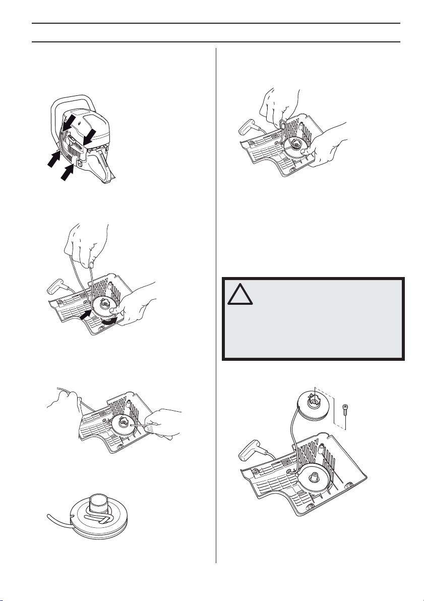
Starter housing
Checking the starter cord
• Loosen the screws that hold the starter against the
crankcase and remove the starter.
Tensioning the recoil spring
• Guide the cord through the cut-out in the periphery of
the pulley and wind the cord 3 times clockwise around
the centre of the starter pulley.
• Pull the cord out about 30 cm and lift it into the cut-out
in the periphery of the starter pulley. When the cord is
intact: Release the spring tension by letting the pulley
rotate slowly backwards.
Changing a broken or worn starter cord
• Remove any remnants of the old starter cord and
check that the return spring works. Insert the new
starter cord through the hole in the starter housing
and in the cord pulley.
• Secure the starter cord around the cord pulley as
illustrated. Tighten the fastening well and ensure that
the free end is as short as possible. Secure the end of
the starter cord in the starter handle.
• Now pull the starter handle and in doing so tension the
spring. Repeat the procedure once more, but this time
with four turns.
• Note that the starter handle is drawn to its correct
home position after tensioning the spring.
• Check that the spring is not drawn to its end position
by pulling out the starter line fully. Slow the starter
pulley with your thumb and check that you can turn the
pulley at least a further half turn.
Changing a broken recoil spring
WARNING! When the recoil spring is
wound up in the starter housing it is
under tension and can, if handled
carelessly, pop out and cause personal
injury.
Always be careful when changing the
recoil spring or the starter cord. Always
wear protective goggles.
• Undo the bolt in the centre of the pulley and remove
the pulley.
• Carefully lift the cover that protects the spring. Bear in
mind that the return spring lies tensioned in the starter
housing.
English – 15

• Carefully remove the spring using pilers.
MAINTENANCE
• Loosen the screws. Remove the air filter cover.
• Lubricate the recoil spring with light oil. Fit the pulley
and tension the recoil spring.
Fitting the starter
• To fit the starter, first pull out the starter cord and place
the starter in position against the crankcase. Then
slowly release the starter cord so that the pulley
engages with the pawls.
• Tighten the screws.
Fuel system
General
• Check that the fuel cap and its seal are not damaged.
• Check the fuel hose. Replace when damaged.
Fuel filter
• The fuel filter sits inside the fuel tank.
• The fuel tank must be protected from contamination
when filling. This reduces the risk of operating
disturbances caused by blockage of the fuel filter
located inside the tank.
• The filter cannot be cleaned but must be replaced with
a new filter when it is clogged.
changed at least once per year.
The filter should be
Air filter
The air filter only needs to be checked if the engine drops
in power.
• Check the air filter and replace if necessary.
Replacing the air filter
NOTICE! The air filter must not be cleaned or blown
clean with compressed air. This will damage the filter.
• Loosen the screw.
• Replace the air filter.
Drive gear, clutch
• Check the clutch centre, drive gear and clutch spring
for wear.
16 – English

TROUBLESHOOTING
Troubleshooting schedule
WARNING! If service operations or troubleshooting does not require the machine to be on, the
engine should be switched off, and the stop switch in STOP position.
!
Problem Probable cause Potential Solution
See instructions under the heading
Starting and stopping.
Make sure that the stop switch (STOP) is
in the left position.
Tighten the belt / Replace the belt with a
new one
Check the air filter and replace if
necessary.
Check that the cutting blade is fitted
correctly and does not show signs of
damage. See the instructions in the
sections "Cutting blades" and "Assembly
and adjustments".
Change the blade and make sure it is
intact.
Contact your service agent.
Clean the machine’s air intake/cooling
flanges
Always cut at full throttle.
Check clutch / contact your service agent
The machine does not start
The blade rotates at idle
The blade does not rotate while
throttling up
The machine has no power while
attempting to throttle up
Vibration levels are too high
Temperature of the machine is too
high
Incorrect starting procedure.
Stop switch in the right (STOP)
position
There is no fuel in the fuel tank Refill with fuel
Spark plug defective Replace the spark plug.
Defective clutch Contact your service agent.
Idle speed too high Adjust the idle speed
Defective clutch Contact your service agent.
Belt too loose or defective
Defective clutch Contact your service agent.
Blade fitted incorrectly Make sure the blade is properly installed.
Clogged air filter
Clogged fuel filter Replace the fuel filter.
Fuel tank vent blocked Contact your service agent.
Blade fitted incorrectly
Blade defective
Vibration damping elements
defective
Air intake or cooling flanges
blocked
Belt slipping Check belt / adjust the tension
Clutch slipping / is defective
English – 17

TECHNICAL DATA
Technical data
Engine
Cylinder displacement, cm3/cu.in 119/7,3
Cylinder bore, mm/inch 60/2,4
Stroke, mm/inch 42/1,7
Idle speed, rpm 2700
Wide open throttle - no load, rpm 9300 (+/- 150)
Power, kW/hp @ rpm 5,8/7,9 @ 8400
Ignition system
Manufacturer of ignition system SEM
Type of ignition system CD
Spark plug NGK BPMR 7A
Electrode gap, mm/inch 0,5/0,02
Fuel and lubrication system
Manufacturer of carburettor Walbro
Carburettor type RWG1
Fuel tank capacity, litre/US fl. Oz 1,25/42
Weight
Weight without fuel, kg/lb 9,9/21,8
Noise emissions (see note 1)
Sound power level, measured dB(A) 116
Sound power level, guaranteed LWA dB(A) 117
Sound levels (see note 2)
Equivalent sound pressure level at the operator’s ear, dB(A) 104
Note 1: Noise emissions in the environment measured as sound power (LWA) in conformity with EC directive 2000/14/
EC. The difference between guaranteed and measured sound power is that the guaranteed sound power also includes
dispersion in the measurement result and the variations between different machines of the same model according to
Directive 2000/14/EC. Stated data applies to power unit only without OEM cutting attachment.
Note 2: Equivalent sound pressure level, according to EN ISO 19432, is calculated as the time-weighted energy total for
different sound pressure levels under various working conditions. Reported data for equivalent sound pressure level for
the machine has a typical statistical dispersion (standard deviation) of 1 dB(A). Stated data applies to power unit only
without OEM cutting attachment.
18 – English

TECHNICAL DATA
Declaration of conformity of partly completed machinery
(Applies to Europe only)
Husqvarna AB, SE-561 82 Huskvarna, Sweden, tel +46-36-146500, declares under sole responsibility that the partly
completed power cutter
text on the rating plate with subsequent serial number), complies with the requirements of the COUNCIL’S DIRECTIVES:
• of May 17, 2006 ”relating to machinery” 2006/42/EC.
• of February 26, 2014 ”relating to electromagnetic compatibility” 2014/30/EU.
• of May 8, 2000 ”relating to the noise emissions in the environment” 2000/14/EC.
The following standards have been applied: EN ISO 12100:2010, EN ISO 14982:2009, CISPR12:2007+AMD1:2009,
EN55012:2008+A1:2009, EN ISO 19432:2012
Husqvarna AB undertakes to transmit, in response to a reasoned request by the national authorities, relevant information
on this partly completed machinery.
Husqvarna AB states that this partly completed machinery must not be put into service until the final machinery into
which it is to be incorporated has been declared in conformity with the provisions of directive 2006/42/EC.
Gothenburg, 25 April 2016
Joakim Ed
Global R & D Director
Construction Equipment Husqvarna AB
(Authorized representative for Husqvarna AB and responsible for technical documentation.)
Husqvarna K 1270R from 2016’s serial numbers and onwards (the year is clearly stated in plain
English – 19

FEDERAL EMISSION CONTROL WARRANTY STATEMENT
YOUR WARRANTY RIGHTS AND OBLIGATIONS
The EPA (The US Environmental Protection Agency),
Environment Canada and Husqvarna Construction
Products are pleased to explain the emissions control
system warranty on your 2009 and later small nonroad
engine. In U.S. and Canada, new small nonroad engines
must be designed, built and equipped to meet the federal
stringent anti-smog standards. Husqvarna Construction
Products must warrant the emission control system on
your small nonroad engine for the period of time listed
below provided there has been no abuse, neglect or
improper maintenance of your unit. Your emmission
control system includes Parts such as the carburetor and
the ignition system. Where a warrantable condition exists,
Husqvarna Construction Products will repair your small
nonroad engine at no cost to you. Expenses covered
under warranty include diagnosis, parts and labor.
MANUFACTURER´S WARRANTY COVERAGE
The 2009 and later small nonroad engines are warranted
for two years. If any emission related part on you engine
(as listed above) is defective, the part will be repaired or
replaced by Husqvarna Construction Products.
OWNER´S WARRANTY RESPONSIBILITIES
As the small nonroad engine owner, you are responsible
for the performance of the required maintenance listed in
your Operator´s Manual. Husqvarna Construction
Products recommends that you retain all receipts
covering maintenance on your small nonroad engine, but
Husqvarna Construction Products cannot deny warranty
solely for the lack of receipts or for your failure to ensure
the performance of all scheduled maintenance. As the
small nonroad engine owner, you should, however, be
aware that Husqvarna Construction Products may deny
you warranty coverage if your small nonroad engine or a
part of it has failed due to abuse, neglect, improper
maintenance, unapproved modifications or the use of
parts not made or approved by the original equipment
manufacturer. You are responsible for presenting your
small nonroad engine to a Husqvarna Construction
Products authorized servicing dealer as soon as a
problem exists. The warranty repairs should be completed
in a reasonable amount of time, not to exceed 30 days. If
you have a question regarding your warranty coverage,
you should contact the Husqvarna Construction Products
service center at 1-800-288-5040 or
www.USA.husqvarnacp.com.
WARRANTY COMMENCEMENT DATE
The warranty period begins on the date small nonroad
engine is delivered.
LENGTH OF COVERAGE
Husqvarna Construction Products warrants to the initial
owner and each subsequent purchaser that the engine is
free from defects in materials and workmanship which
cause the failure of a warranted part for a period of two
years.
WHAT IS COVERED
REPAIR OR REPLACEMENT OF PARTS Repair or
replacement of any warranted part will be performed at no
charge to the owner at an approved Husqvarna
Construction Products servicing dealer. If you have a
question regarding your warranty coverage, you should
contact the Husqvarna Construction Products service
center at 1-800-288-5040 or
www.USA.husqvarnacp.com.
WARRANTY PERIOD Any warranted part which is not
scheduled for replacement as required maintenance, or
which is scheduled only for regular inspection to the effect
of 'repair or replace as necessary” shall be warranted for
2 years. Any warranted part which is scheduled for
replacement as required maintenance shall be warranted
for the period of time up to the first scheduled
replacement point for that part.
DIAGNOSIS The owner shall not be charged for
diagnostic labor which leads to the determination that a
warranted part is defective, if the diagnostic work is
performed at an approved Husqvarna Construction
Products servicing dealer.
CONSEQUENTIAL DAMAGES Husqvarna Construction
Products may be liable for damages to other engine
components caused by the failure of a warranted part still
under warranty.
WHAT IS NOT COVERED
All failures caused by abuse, neglect or improper
maintenance are not covered.
ADD -ON OR MODIFIED PARTS
The use of add-on or modified parts can be grounds for
disallowing a warranty claim. Husqvarna Construction
Products is not liable to cover failures of warranted parts
caused by the use of add-on or modified parts.
HOW TO FILE A CLAIM
If you have a question regarding your warranty coverage,
you should contact the Husqvarna Construction Products
service center at 1-800-288-5040 or
www.USA.husqvarnacp.com.
WHERE TO GET WARRANTY SERVICE
Warranty services or repairs shall be provided at all
Husqvarna Construction Products authorized servicing
dealers.
20 – English

FEDERAL EMISSION CONTROL WARRANTY STATEMENT
MAINTENANCE, REPLACEMENT AND REPAIR OF EMISSION-RELATED PARTS
Any Husqvarna Construction Products approved
replacement part used in the performance of any
warranty maintenance or repairs on emission-related
parts, will be provided without charge to the owner if the
part is under warranty.
EMISSION CONTROL WARRANTY PARTS LIST
1 Carburetor and internal parts
2 Intake pipe, airfilter holder and carburetor bolts.
3 Airfilter and fuelfilter covered up to maintenance
schedule.
4 Ignition System
1Spark Plug, covered up to maintenance schedule
2Ignition Module
5 Fuel tank, line and cap
MAINTENANCE STATEMENT
The owner is responsible for the performance of all
required maintenance, as defined in the operator’s
manual.
English – 21
EXPLICATION DES SYMBOLES
Symboles sur la machine
AVERTISSEMENT! La machine utilisée
de manière imprudente ou inadéquate
peut devenir un outil dangereux, pouvant
causer des blessures graves voire
mortelles à l’utilisateur et aux autres
personnes présentes.
Lire attentivement et bien assimiler le
manuel d’utilisation avant d’utiliser la
machine.
Utiliser les équipements de protection
personnelle. Voir au chapitre
Ӄquipement de protection
personnelle”.
AVERTISSEMENT! Au cours de la
découpe, la poussière générée peut
occasionner des blessures si elle est
aspirée. Utiliser une protection
respiratoire approuvée. Éviter
d'inhaler des vapeurs d'essences et
des gaz d'échappement. Veiller à disposer d'une bonne
ventilation.
AVERTISSEMENT! Les rebonds
peuvent être soudains, rapides et
violents et peuvent générer des
blessures pouvant être mortelles. Lire
et assimiler les instructions du manuel
avant d'utiliser la machine.
AVERTISSEMENT! Les étincelles du
disque de coupe peuvent provoquer
un incendie en cas de contact avec
des matières inflammables tels que
l’essence, le bois, l’herbe sèche.
Vérifier que les lames ne comportent
ni fissures ni autre dommage.
Remplissage d’essence/de
mélange d'huile
Autocollant des
instructions de
démarrage Voir les
instructions au chapitre
Démarrage et arrêt.
Plaque d’identification
Rangée 1 : Marque, modèle
(X, Y)
Rangée 2 : N° de série avec
date de fabrication (y, W, X)
Année, semaine, n
° de
XXXXXXXXX YYYY
s / n YYYY WWXXXXX
Huskvarna, SWEDEN
:
XXXXXXXXXXXX (YY)
XXX XX XX-XX
Husqvarna AB
XXXXXXXXXXX
séquence
Rangée 3 : N° de produit (X)
Rangée 4 : Fabricant
Rangée 5 : Adresse du fabricant
Rangées 6-7 : Type d’homologation CE, le cas échéant
(X, Y)
: Code d’homologation, étape d’homologation
La période de conformité des émissions à laquelle il est
fait référence sur l’étiquette de conformité des émissions
indique le nombre d’heures de fonctionnement pour
lesquelles il a été établi que le moteur répond aux
exigences californiennes et fédérales en matière
d’émissions.
EMISSION CONTROL INFORMATION
HUSQVARNA AB, HUSKVARNA, MADE IN SWEDEN
THIS ENGINE MEETS U.S. EPA EXH/EVP
OPERATOR’S MANUAL FOR MAINTENANCE
SPECIFICATIONS AND ADJUSTMENTS.
EMISSIONS COMPLIANCE PERIOD: 300 HRS
®
REGS FOR 2016 SORE. REFER TO
2016
EM/N74ccB0
30-5
43
6
105
Les autres symboles/autocollants présents sur la
machine concernent des exigences de certification
spécifiques à certains marchés.
N’utilisez pas de lames de scie circulaire.
Starter.
Décompresseur
Poignée de lanceur
22 – French
EXPLICATION DES SYMBOLES
Explication des niveaux d'avertissement
Il existe trois niveaux d'avertissement.
AVERTISSEMENT!
AVERTISSEMENT! Symbole utilisé en
cas de risque de blessures très graves
!
ou de mort pour l'utilisateur ou de
dommages pour les environs si les
instructions du manuel ne sont pas
suivies.
REMARQUE !
REMARQUE ! Symbole utilisé en cas de
risque de blessures pour l'utilisateur ou
!
de dommages pour les environs si les
instructions du manuel ne sont pas
suivies.
ATTENTION !
ATTENTION ! Symbole utilisé en cas de risque de
dommages pour les matériaux ou la machine si les
instructions du manuel ne sont pas suivies.
French – 23

SOMMAIRE
Sommaire Contrôler les points suivants
EXPLICATION DES SYMBOLES
Symboles sur la machine ...................................... 22
Explication des niveaux d'avertissement .............. 23
SOMMAIRE
Sommaire ............................................................. 24
Contrôler les points suivants avant la mise en
marche: .................................................................
PRÉSENTATION
Cher client, ............................................................ 25
Conception et propriétés ....................................... 25
QUELS SONT LES COMPOSANTS?
Quels sont les composants de la machine ? ........ 26
ÉQUIPEMENT DE SÉCURITÉ DE LA MACHINE
Généralités ........................................................... 27
COMMANDE
Équipement de protection ..................................... 29
MANIPULATION DU CARBURANT
Généralités ........................................................... 30
Carburant .............................................................. 30
Remplissage de carburant .................................... 31
Transport et rangement ......................................... 31
DÉMARRAGE ET ARRÊT
Avant le démarrage ............................................... 32
Démarrage ............................................................ 32
Arrêt ...................................................................... 34
ENTRETIEN
Généralités ........................................................... 35
Schéma d’entretien ............................................... 35
Nettoyage .............................................................. 35
Contrôle fonctionnel .............................................. 36
RECHERCHE DE PANNES
Plan de recherche de pannes ............................... 39
CARACTÉRISTIQUES TECHNIQUES
Caractéristiques techniques ................................. 40
Déclaration de conformité de quasi-machine ....... 41
DÉCLARATION DE GARANTIE POUR LA
LUTTE CONTRE LES ÉMISSIONS
VOS DROITS ET OBLIGATIONS EN GARANTIE 42
avant la mise en marche:
24
ATTENTION ! Commission californienne chargée de
la qualité de l’air (CARB)
considérée comme une application tout-terrain de
présérie selon les normes CARB. L’EPA aux États-Unis
est la seule entité habilitée à établir des normes
antipollution pour les équipements de construction de
présérie. Pour plus d’informations, consultez
www.arb.ca.gov/msprog/offroad/preempt.htm
: Cette machine est
24 – French

PRÉSENTATION
Cher client,
Nous vous remercions d'avoir choisi un produit
Husqvarna !
Nous espérons que cette machine vous donnera toute
satisfaction et qu’elle vous accompagnera pendant de
longues années. L’achat de l’un des nos produits garantit
une assistance professionnelle pour l’entretien et les
réparations. Si la machine n’a pas été achetée chez l’un
de nos revendeurs autorisés, demandez l’adresse de
l’atelier d’entretien le plus proche.
Ce mode d’emploi est précieux. Veillez à ce qu'il soit
toujours à portée de main sur le lieu de travail. En suivant
les instructions qu’il contient (utilisation, révision,
entretien etc.), il est possible d’allonger considérablement
la durée de vie de la machine et d’augmenter sa valeur
sur le marché de l’occasion. En cas de vente de la
machine, ne pas oublier de remettre le manuel
d’utilisation au nouveau propriétaire.
Plus de 300 ans d'innovation
Husqvarna AB est une entreprise suédoise qui a vu le
jour en 1689 lorsque le roi Karl XI décida de construire un
arsenal pour la fabrication des mousquets. À l'époque, les
compétences en ingénierie à la base du développement
de certains des produits leaders du marché mondial dans
des domaines tels que les armes de chasse, les vélos, les
motocycles, l'électroménager, les machines à coudre et
les produits d'extérieur, étaient déjà solides.
Husqvarna est le premier fournisseur mondial de produits
motorisés pour utilisation en extérieur dans la foresterie,
l'entretien de parcs, de pelouses et de jardins, ainsi que
d'équipements de coupe et d'outils diamant destinés aux
industries de la construction et de la pierre.
Responsabilité du propriétaire
Il est de la responsabilité du propriétaire/de l’employeur
de s’assurer que l’utilisateur possède les connaissances
nécessaires pour manipuler la machine en toute sécurité.
Les responsables et les utilisateurs doivent avoir lu et
compris le Manuel d’utilisation. Ils doivent avoir
conscience :
• Des instructions de sécurité de la machine.
• Des diverses applications de la machine et de ses
limites.
• De la façon dont la machine doit être utilisée et
entretenue.
La législation nationale peut réglementer l'utilisation de
cette machine. Recherchez la législation applicable dans
le lieu où vous travaillez avant d'utiliser la machine.
Les législations locales peuvent limiter l’utilisation de
cette machine. Recherchez les législations applicables
pour le lieu où vous travaillez avant d’utiliser la machine.
Droit de réserve du fabricant
Husqvarna peut éditer des informations complémentaires
concernant l’utilisation de ce produit en toute sécurité
après la publication du présent manuel. Il incombe au
propriétaire de se tenir informé des méthodes d’utilisation
les plus sûres.
Husqvarna AB travaille continuellement au
développement de ses produits et se réserve le droit d’en
modifier, entre autres, la conception et l’aspect sans
préavis.
Pour obtenir des informations et une assistance client,
contactez-nous via notre site Web
: www.husqvarna.com
Conception et propriétés
Cette unité électrique est une machine partiellement
aboutie, destinée à la conception OEM d’une
découpeuse manuelle haute vitesse.
Certaines des caractéristiques uniques de votre produit
sont décrites ci-dessous.
Active Air Filtration™
Épuration centrifuge de l'air pour une durée de vie
supérieure et un entretien moins fréquent.
SmartCarb™
Un filtre compensateur automatique intégré maintient une
puissance élevée et réduit la consommation en carburant.
X-Torq®
Le moteur X-Torq® apporte un couple encore plus
accessible pour une gamme de vitesses encore plus
large, et donc une capacité de découpe maximale. XTorq® réduit la consommation en carburant de jusqu’à 20
% et les émissions de jusqu’à 60 %.
EasyStart
Le moteur et le lanceur sont conçus de façon à assurer un
démarrage rapide et facile de la machine. Réduit la
résistance à la traction dans la corde du lanceur de
jusqu’à 40 %. (Réduit la compression au démarrage.)
Système anti-vibrations efficace
Bras et aiguilles de rechange pour les amortisseurs de
vibrations efficaces.
French – 25
QUELS SONT LES COMPOSANTS?
1
16
15
14
12
13
Quels sont les composants de la machine ?
1 Poignée avant
2 Décompresseur
3 Carter de filtre à air
4 Capot de cylindre
5 Starter avec blocage du ralenti accéléré
6 Bouton d’arrêt
7 Bouchon du réservoir de carburant
8 Lanceur
9 Poignée de lanceur
11
10
9
8
7
17
10 Plaque d’identification
11 Silencieux
12 Pignon d’entraînement et embrayage
13 Commande de l’accélération
14 Blocage de l’accélération
15 Autocollant des instructions de démarrage
16 Autocollant d’information et d’avertissement
17 Clé universelle, à pointe à six lobes
2
3
4
5
6
26 – French
ÉQUIPEMENT DE SÉCURITÉ DE LA MACHINE
Généralités
AVERTISSEMENT! Ne jamais utiliser une
machine dont les équipements de
!
sécurité sont défectueux. Si les
contrôles ne donnent pas de résultat
positif, confier la machine à un atelier
spécialisé.
Le moteur doit être éteint et le bouton
d'arrêt en position STOP.
Ce chapitre présente les équipements de sécurité de la
machine, leur fonction, comment les utiliser et les
maintenir en bon état.
Blocage de l’accélération
Le blocage de l'accélération est conçu pour empêcher
toute activation involontaire de la commande de
l'accélération. Lorsque le blocage (A) est enfoncé, la
commande de l'accélération est embrayée (B).
Le blocage reste enfoncé tant que la commande
d’accélération est sollicitée. Lorsque la poignée est
relâchée, la gâchette d’accélération et le blocage de
l’accélération retrouvent leurs positions initiales. Ceci
s’effectue à l’aide de deux systèmes de retour par
ressorts, indépendants l’un de l’autre. En position initiale,
la gâchette d’accélération est automatiquement bloquée
au régime de ralenti.
Vérification du blocage de la commande
d'accélération
• Vérifier d’abord que la commande de l’accélération
est bloquée en position de ralenti quand le blocage de
l’accélération est en position initiale.
• Vérifier que le blocage de l’accélération, la
commande d’accélération et leurs ressorts de rappel
fonctionnent correctement.
• Démarrer la découpeuse et donner les pleins gaz.
Relâcher la commande de l'accélération et contrôler
que le disque découpeur s'arrête et qu'il demeure
immobile. Si le disque découpeur tourne quand la
commande est en position de ralenti, il convient de
contrôler le réglage du ralenti du carburateur. Voir les
instructions au chapitre «
Entretien ».
Bouton d’arrêt
Le bouton d’arrêt est utilisé pour arrêter le moteur.
Vérification du bouton d'arrêt
• Mettre le moteur en marche et s’assurer qu’il s’arrête
lorsque le bouton d’arrêt est amené en position
d’arrêt.
• Appuyer sur le blocage de l’accélération et vérifier
qu’il revient de lui-même en position initiale quand il
est relâché.
French – 27
ÉQUIPEMENT DE SÉCURITÉ DE LA MACHINE
!
Système anti-vibrations
Silencieux
AVERTISSEMENT! Une exposition
excessive aux vibrations peut entraîner
!
des troubles circulatoires ou nerveux
chez les personnes sujettes à des
troubles cardio-vasculaires. Consultez
un médecin en cas de symptômes liés à
une exposition excessive aux vibrations.
De tels symptômes peuvent être:
engourdissement, perte de sensibilité,
chatouillements, picotements, douleur,
faiblesse musculaire, décoloration ou
modification épidermique. Ces
symptômes affectent généralement les
doigts, les mains ou les poignets. Ces
symptômes peuvent être accentués par
le froid.
• La machine est équipée d’un système anti-vibrations
conçu pour assurer une utilisation aussi confortable
que possible.
• Le système anti-vibrations réduit la transmission des
vibrations de l’unité moteur/l’équipement de coupe à
l’unité que constituent les poignées. Le corps du
moteur, y compris l'équipement de coupe, est
suspendu à l'unité poignées par l'intermédiaire de
blocs anti-vibrants.
Vérification du système anti-vibrations
AVERTISSEMENT! Le moteur doit être
éteint et le bouton d'arrêt en position
!
STOP.
AVERTISSEMENT! N'utilisez jamais une
machine sans silencieux ou avec un
silencieux défectueux. Si le silencieux
est défectueux, le niveau sonore et le
risque d’incendie augmentent
considérablement. Veillez à disposer des
outils nécessaires à l’extinction d’un feu.
Le silencieux devient très chaud pendant
et après l’utilisation, ainsi qu’au cours du
fonctionnement au ralenti. Soyez attentif
au risque d’incendie, surtout à proximité
de produits inflammables et/ou en
présence de gaz.
Veillez à disposer des outils nécessaires
à l’extinction d’un feu.
Le silencieux est conçu pour réduire au maximum le
niveau sonore et détourner les gaz d’échappement loin
de l’utilisateur.
Contrôle du silencieux
Contrôler régulièrement que le silencieux est entier et
qu’il est attaché correctement.
• Contrôler régulièrement les éléments anti-vibrations
afin de détecter toute éventuelle fissure ou
déformation. Les remplacer s'ils sont endommagés.
• S’assurer de la bonne fixation des éléments antivibrations entre l’unité moteur et l’ensemble poignée.
28 – French
COMMANDE
!
Équipement de protection
Généralités
Ne jamais utiliser une machine s’il n’est pas possible
d’appeler au secours en cas d’accident.
Équipement de protection personnelle
Un équipement de protection personnelle homologué doit
impérativement être utilisé lors de tout travail avec la
machine. L’équipement de protection personnelle
n’élimine pas les risques mais réduit la gravité des
blessures en cas d’accident. Demander conseil au
concessionnaire afin de choisir un équipement adéquat.
AVERTISSEMENT! L’utilisation de
produits tels que des ciseaux, des
!
disques, des forets, des disques fins ou
des formes peut générer de la poussière
et des vapeurs pouvant contenir des
substances chimiques toxiques. Vérifiez
la composition du matériel avec lequel
vous travaillez et portez un masque
respiratoire adapté.
Une exposition prolongée au bruit risque
de causer des lésions auditives
permanentes. Toujours utiliser des
protecteurs d'oreille agréés. Soyez
toujours attentifs aux signaux d’alerte ou
aux appels en portant des protègeoreilles. Enlevez-les sitôt le moteur
arrêté.
Autre équipement de protection
REMARQUE ! Lorsque vous travaillez
avec la machine, des étincelles peuvent
se former et mettre le feu. Gardez
toujours à portée de main les outils
nécessaires à l'extinction d'un feu.
• Extincteur
• Trousse de premiers secours
Toujours utiliser:
• Casque de protection homologué
• Protecteur d’oreilles
• Des protège-yeux homologués. L’usage d’une visière
doit toujours s’accompagner du port de lunettes de
protection homologuées. Par lunettes de protection
homologuées, on entend celles qui sont en conformité
avec les normes ANSI Z87.1 (États-Unis) ou EN 166
(pays de l’UE). La visière doit être conforme à la
norme EN 1731.
• Masque respiratoire
• Gants solides permettant une prise sûre.
• Vêtements confortables, robustes et serrés qui
permettent une liberté totale de mouvement. La
découpe crée des étincelles qui peuvent enflammer
les vêtements. Husqvarna vous recommande de
porter du coton ignifugé ou du denim épais. Ne portez
pas de vêtements composés de matières comme le
nylon, le polyester ou la rayonne. Si elles
s’enflamment, ces matières peuvent fondre et adhérer
à la peau. Ne portez pas de shorts
• Bottes avec coquille en acier et semelle
antidérapante.
French – 29

MANIPULATION DU CARBURANT
Généralités
AVERTISSEMENT! Faire tourner un
moteur dans un local fermé ou mal aéré
!
peut causer la mort par asphyxie ou
empoisonnement au monoxyde de
carbone. Utilisez des ventilateurs pour
assurer une bonne circulation de l'air
lorsque vous travaillez dans des
tranchés ou des fossés d'une profondeur
supérieure à un mètre.
Le carburant et les vapeurs de carburant
sont inflammables et peuvent causer des
blessures graves en cas d’inhalation ou
de contact avec la peau. Il convient donc
d’observer la plus grande prudence lors
de la manipulation du carburant et de
veiller à disposer d’une bonne aération.
Les gaz d’échappement du moteur sont
très chauds et peuvent contenir des
étincelles pouvant provoquer un
incendie. Par conséquent, ne jamais
démarrer la machine dans un local clos
ou à proximité de matériaux
inflammables!
Ne fumez jamais ni ne placez d’objet
chaud à proximité du carburant.
Carburant
ATTENTION ! La machine est équipée d’un moteur
deux temps et doit toujours être alimentée avec un
mélange d'essence et d’huile deux temps. Afin d’obtenir
un mélange approprié, il est important de mesurer avec
précision la quantité d’huile à mélanger. Pour le
mélange de petites quantités de carburant, la moindre
erreur peut sérieusement affecter le rapport du
mélange.
Essence
• Utiliser une essence de qualité, avec ou sans plomb.
• Le taux d’octane minimum recommandé est de 90
(RON). Si l’on fait tourner le moteur avec une essence
d’un taux d’octane inférieur à 90, un cognement
risque de se produire, résultant en une augmentation
de la température du moteur pouvant causer de
graves avaries du moteur.
• Si on travaille en permanence à des régimes élevés,
il est conseillé d’utiliser un carburant d’un indice
d’octane supérieur.
Carburant écologique
HUSQVARNA recommande l'utilisation d'une essence
écologique (dite essence alkylat), soit une essence deux
temps prémélangée Aspen, soit une essence écologique
pour moteurs quatre temps mélangée avec de l'huile deux
temps selon les instructions ci-dessous. Noter qu'il peut
être nécessaire de procéder à un réglage du carburateur
lors du changement de type d'essence (voir les
instructions à la section Carburateur).
Possibilité d’utiliser du carburant mélangé à base
d’éthanol, E10 (la teneur en éthanol ne doit pas dépasser
10 %). L’utilisation de carburants mélangés contenant
plus d’éthanol que l’E10 perturbe le fonctionnement de la
machine et risque d’endommager le moteur.
Huile deux temps
• Pour obtenir un fonctionnement et des résultats
optimaux, utiliser une huile moteur deux temps
HUSQVARNA fabriquée spécialement pour nos
moteurs deux temps à refroidissement à air.
• Ne jamais utiliser d’huile deux temps pour moteurs
hors-bord refroidis par eau, appelée huile outboard
(désignation TCW).
• Ne jamais utiliser d’huile pour moteurs à quatre
temps.
Mélange
• Toujours effectuer le mélange dans un récipient
propre et destiné à contenir de l’essence.
• Toujours commencer par verser la moitié de l’essence
à mélanger. Verser ensuite la totalité de l’huile.
Mélanger en secouant le récipient. Enfin, verser le
reste de l’essence.
• Mélanger (secouer) soigneusement le mélange avant
de faire le plein du réservoir de la machine.
• Ne jamais préparer plus d’un mois de consommation
de carburant à l’avance.
Rapport de mélange
• 1:50 (2%) avec huile deux temps HUSQVARNA ou
équivalent.
Essence, litres Huile deux temps, litres
2% (1:50)
5 0,10
10 0,20
15 0,30
20 0,40
• 1:33 (3 %) avec des huiles de catégorie JASO FB ou
ISO EGB formulées pour moteurs deux temps à
refroidissement à air ou mélange selon les consignes
du fabricant d’huile.
30 – French

MANIPULATION DU CARBURANT
Remplissage de carburant
AVERTISSEMENT! Les mesures de
sécurité ci-dessous réduisent le risque
!
d’incendie:
Ne fumez jamais ni ne placez d’objet
chaud à proximité du carburant.
Arrêter le moteur et le laisser refroidir
pendant quelques minutes avant de faire
le plein. Le moteur doit être éteint et le
bouton d'arrêt en position STOP.
Ouvrir le bouchon du réservoir lentement
pour laisser baisser la surpression
pouvant régner dans le réservoir.
Nettoyez le pourtour du bouchon de
réservoir.
Serrer soigneusement le bouchon du
réservoir après le remplissage.
Si le bouchon n’est pas serré
correctement, il risque de s’ouvrir à
cause des vibrations et du carburant
peut alors s’échapper du réservoir de
carburant, entraînant un risque
d’incendie.
Avant de mettre la machine en marche, la
déplacer à au moins 3 mètres de l’endroit
où a été fait le plein.
Transport et rangement
• Transporter et ranger la machine et le carburant de
façon à éviter que toute fuite ou émanation éventuelle
entre en contact avec une flamme vive ou une
étincelle: machine électrique, moteur électrique,
contact/interrupteur électrique ou chaudière.
• Lors du stockage et du transport de carburant,
toujours utiliser un récipient homologué et conçu à cet
effet.
Remisage prolongé
• Lors des remisages de la machine, vider le réservoir
de carburant. S’informer auprès d’une station-service
comment se débarrasser du carburant résiduel.
Ne jamais démarrer la machine:
• Si du carburant ou de l'huile moteur ont été répandus
sur la machine. Essuyer soigneusement toutes les
éclaboussures et laisser les restes d'essence
s'évaporer.
• Si vous avez renversé du carburant sur vous ou sur
vos vêtements, changez de vêtements. Lavez les
parties du corps qui ont été en contact avec le
carburant. Utilisez de l’eau et du savon.
• S’il y a fuite de carburant. Vérifier régulièrement que
le bouchon du réservoir et la conduite de carburant ne
fuient pas.
• À moins que le bouchon du réservoir ne soit
correctement serré après avoir fait le plein.
French – 31

DÉMARRAGE ET ARRÊT
Avant le démarrage
AVERTISSEMENT! Contrôler les points
suivants avant la mise en marche: Lire
!
attentivement et bien assimiler le manuel
d’utilisation avant d’utiliser la machine.
Portez un équipement de protection
personnelle. Reportez-vous au chapitre
Équipement de protection personnelle.
Ne démarrez pas la machine sans avoir
monté la courroie et le carter de la
courroie. Sinon, l’embrayage risque de
se détacher et de provoquer des
blessures personnelles.
Vérifiez que le bouchon du réservoir est
correctement sécurisé et qu'il n'y a pas
de fuite de carburant.
Veiller à ce qu’aucune personne non
autorisée ne se trouve dans la zone de
travail pour éviter le risque de blessures
graves.
• Effectuez un entretien quotidien. Voir les instructions
au chapitre «
Démarrage
!
Moteur froid:
Entretien ».
AVERTISSEMENT! Le disque se met à
tourner dès le lancement du moteur.
Vérifier qu’il tourne librement.
lancé, le décompresseur se remet automatiquement
en position initiale.
• Saisir la poignée avant avec la main gauche. Placer le
pied droit sur la partie inférieure de la poignée arrière
et appuyer la machine sur le sol. Tirez la poignée du
lanceur d’un coup sec avec la main droite jusqu’à ce
que le moteur démarre.
du lanceur autour de la main.
• La machine s'arrête lorsque le moteur chauffe parce
que la commande de starter est tirée.
Ne jamais enrouler la corde
• Veiller à ce que le bouton d'arrêt (STOP) soit sur sa
position de gauche.
• La position de ralenti accéléré et le starter sont
engagés en tirant complètement le starter.
• Décompresseur: Enfoncer le décompresseur pour
réduire la pression dans le cylindre et faciliter le
démarrage de la découpeuse. Toujours utiliser le
décompresseur au démarrage. Une fois le moteur
32 – French
• Appuyez sur la commande de starter et sur le
décompresseur.
• Tirez la poignée du lanceur jusqu'à ce que le moteur
démarre.

DÉMARRAGE ET ARRÊT
• Lorsque la machine démarre, appuyez sur la gâchette
d’accélération pour désengager le ralenti accéléré
machine tourne alors au ralenti.
ATTENTION ! Tirez lentement sur la corde du lanceur
de la main droite jusqu’à ce qu’une résistance se fasse
sentir (les cliquets se mettent en prise), puis tirez
plusieurs fois rapidement et avec force.
Ne pas sortir complètement la corde du lanceur et ne
pas lâcher la poignée avec la corde du lanceur
complètement sortie. Cela pourrait endommager la
machine.
Avec un moteur chaud :
• Veiller à ce que le bouton d'arrêt (STOP) soit sur sa
position de gauche.
; la
lanceur d’un coup sec avec la main droite jusqu’à ce
que le moteur démarre.
du lanceur autour de la main.
• Lorsque la machine démarre, appuyez sur la gâchette
d’accélération pour désengager le ralenti accéléré
machine tourne alors au ralenti.
ATTENTION ! Tirez lentement sur la corde du lanceur
de la main droite jusqu’à ce qu’une résistance se fasse
sentir (les cliquets se mettent en prise), puis tirez
plusieurs fois rapidement et avec force.
Ne pas sortir complètement la corde du lanceur et ne
pas lâcher la poignée avec la corde du lanceur
complètement sortie. Cela pourrait endommager la
machine.
Ne jamais enrouler la corde
; la
• Pour procéder au réglage du starter/ralenti accéléré,
il convient de tirer la commande du starter sur la
position starter puis de la pousser de nouveau. Cela
ne concerne que le réglage du ralenti accéléré, pas le
starter.
• Décompresseur: Enfoncer le décompresseur pour
réduire la pression dans le cylindre et faciliter le
démarrage de la découpeuse. Toujours utiliser le
décompresseur au démarrage. Une fois le moteur
lancé, le décompresseur se remet automatiquement
en position initiale.
• Saisir la poignée avant avec la main gauche. Placer le
pied droit sur la partie inférieure de la poignée arrière
et appuyer la machine sur le sol. Tirez la poignée du
French – 33

DÉMARRAGE ET ARRÊT
AVERTISSEMENT! Lorsque le moteur
tourne, l’échappement contient des
!
produits chimiques comme des
hydrocarbures non brûlés et du
monoxyde de carbone. Le contenu des
gaz d’échappement est connu pour
causer des problèmes respiratoires, des
cancers, des malformations congénitales
ou d’autres problèmes liés à la
reproduction.
Le monoxyde de carbone est incolore et
insipide, mais il est toujours présent
dans les gaz d’échappement. Le début de
l’empoisonnement au monoxyde de
carbone se caractérise par de légers
vertiges qui peuvent ou non être
reconnus par la victime. Une personne
peut s’effondrer ou perdre connaissance
sans aucun avertissement si la
concentration en monoxyde de carbone
est suffisamment élevée. Comme le
monoxyde de carbone est incolore et
inodore, sa présence peut ne pas être
détectée. Dès que des odeurs
d’échappement sont perçues, le
monoxyde de carbone est présent.
N’utilisez jamais une découpeuse à
essence à l’intérieur, dans des tranchées
profondes de plus de 3 pieds (1 mètre)
ou dans toute autre zone mal ventilée.
Veillez à disposer d’une ventilation
adaptée en cas de travail dans des
tranchées ou d’autres espaces confinés.
Arrêt
REMARQUE ! Le disque découpeur
continue à tourner pendant au maximum
!
une minute après l'arrêt du moteur.
(Couchage à la lame.) Assurez-vous que
le disque découpeur peut tourner
librement jusqu'à son arrêt complet.
Toute négligence peut causer de graves
blessures.
• Pour arrêter le moteur, placer le bouton d’arrêt
(STOP) sur sa position de droite.
34 – French

ENTRETIEN
Généralités
AVERTISSEMENT! L’utilisateur ne peut effectuer que les travaux d’entretien et de révision décrits
dans ce manuel d’utilisation. Les mesures plus importantes doivent être effectuées dans un
!
atelier d’entretien agréé.
Le moteur doit être éteint et le bouton d'arrêt en position STOP.
Utiliser les équipements de protection personnelle. Voir au chapitre ”Équipement de protection
personnelle”.
La durée de vie de la machine risque d'être écourtée et le risque d'accidents accru si la
maintenance de la machine n'est pas effectuée correctement et si les mesures d'entretien et/ou de
réparation ne sont pas effectuées de manière professionnelle. Pour obtenir de plus amples
informations, contacter l'atelier de réparation le plus proche.
• Faites régulièrement contrôler la machine par votre revendeur Husqvarna afin qu'il procède aux installations et
réparations adéquates.
Schéma d’entretien
Le calendrier de maintenance vous indique quelles pièces de la machine nécessitent un entretien et à quelle fréquence
cet entretien doit avoir lieu. La fréquence est calculée en fonction de l'utilisation quotidienne de la machine, et peut varier
en fonction du degré d'utilisation.
Entretien quotidien Entretien hebdomadaire Entretien mensuel
Nettoyage Nettoyage Nettoyage
Nettoyage extérieur Bougie
Prise d'air de refroidissement Réservoir d’essence
Contrôle fonctionnel Contrôle fonctionnel Contrôle fonctionnel
Inspection générale Système anti-vibrations Système de carburant
Blocage de l’accélération Silencieux Filtre à air
Bouton d’arrêt Carburateur Roue d'entraînement, embrayage
Lanceur
Nettoyage
Nettoyage extérieur
Nettoyer à l’aide d’un chiffon ou d’une brosse.
French – 35

ENTRETIEN
!
Prise d'air de refroidissement
• Nettoyez la prise d'air de refroidissement lorsque
nécessaire.
Blocage de l’accélération
Le blocage de la gâchette d’accélération est conçu de
manière à empêcher les activations involontaires de la
gâchette d’accélération. Quand le blocage (A) est
enfoncé dans la poignée (= quand l’utilisateur tient la
poignée), la gâchette d’accélération (B) est est libérée.
ATTENTION ! Une prise d'air sale ou bouchée provoque
la surchauffe de la machine, ce qui endommage le
piston et le cylindre.
Bougie
• Si la puissance de la machine est faible, si la machine
est difficile à mettre en marche ou si le ralenti est
irrégulier, toujours commencer par contrôler l’état de
la bougie avant de prendre d’autres mesures.
• Vérifier que le chapeau de bougie et le câble
d’allumage ne sont pas endommagés afin d’éviter tout
risque de choc électrique.
• Si la bougie est encrassée, la nettoyer et contrôler que
l’écartement des électrodes est de 0,5 mm.
Remplacez-les si nécessaire.
ATTENTION ! Toujours utiliser le type de bougie
recommandé! Une bougie incorrecte peut endommager
le piston/le cylindre.
Ces facteurs peuvent concourir à l’apparition de calamine
sur les électrodes, ce qui à son tour entraîne un mauvais
fonctionnement du moteur et des démarrages difficiles.
• Mauvais mélange de l’huile dans le carburant (trop
d’huile ou huile inappropriée).
• La propreté du filtre à air.
Contrôle fonctionnel
Inspection générale
• S’assurer que toutes les vis et tous les écrous sont
bien serrés.
Carburateur
Le carburateur est équipé de pointeaux fixes pour que la
machine reçoive toujours le mélange correct d’air et de
carburant. Procéder comme suit si le moteur manque de
puissance ou accélère mal:
• Contrôler le filtre à air et le remplacer si nécessaire. Si
le problème demeure, contacter un atelier de
réparation autorisé.
Réglage du ralenti
REMARQUE ! S’il est impossible de
régler le régime de ralenti de manière à
immobiliser l’équipement de coupe,
contacter le revendeur ou l’atelier de
réparation. Ne pas utiliser la machine
tant qu’elle n’est pas correctement
réglée ou réparée.
Démarrer le moteur et contrôler le réglage du ralenti.
Lorsque le carburateur est correctement réglé, le disque
découpeur doit rester immobile au régime de ralenti.
• Régler le ralenti à l'aide de la vis T. Si un réglage est
nécessaire, commencer par tourner la vis de ralenti
dans le sens des aiguilles d'une montre jusqu'à ce
que le disque de coupe se mette à tourner. Tourner
ensuite la vis dans le sens contraire des aiguilles
d’une montre jusqu’à ce que le disque cesse de
tourner.
T
Régime de ralenti recommandé: 2700 tr/min
36 – French

ENTRETIEN
!
Lanceur
Contrôle de la corde du lanceur
• Déposer les vis maintenant le lanceur contre le carter
moteur et sortir le lanceur.
Mise sous tension du ressort
• Faire pénétrer la corde dans l’encoche dans la
périphérie de la poulie et faire 3 tours dans le sens
des aiguilles d’une montre autour du centre de la
poulie.
• Tirer la corde d’environ 30 cm et la sortir de l’encoche
à la périphérie de la poulie. Si la corde est entière:
Relâcher la tension du ressort en laissant tourner
lentement la poulie vers l’arrière.
Remplacement d’une corde de lanceur rompue ou
usée
• Retirer les restes de l’ancienne corde du lanceur et
contrôler que le ressort de démarrage fonctionne.
Introduire la nouvelle corde du lanceur dans le trou
dans le corps du lanceur et dans la poulie.
• Bloquer la corde du lanceur autour du centre de la
poulie comme illustré sur la figure. Serrer fermement
la fixation et veiller à ce que l’extrémité libre soit aussi
courte que possible. Attacher l’extrémité de la corde
du lanceur dans la poignée de démarrage.
• Tirer ensuite la poignée de démarrage, ce qui tend le
ressort. Répéter encore une fois la procédure mais
faire quatre tours.
• Observer que la poignée de démarrage est tirée dans
la position correcte quand le ressort est tendu.
• Contrôler que le ressort n’est pas tiré jusqu’à sa
position extrême et tirer la corde de lanceur au
maximum. Freiner la poulie avec le pouce et contrôler
que le poulie peut encore être tournée d’un demi tour.
Remplacement d’un ressort de rappel rompu
AVERTISSEMENT! Le ressort de rappel
est tendu et risque, en cas de
manipulation imprudente, de sortir du
boîtier et de causer des blessures.
Observer la plus grande prudence lors
du remplacement du ressort ou de la
corde. Toujours porter des lunettes
protectrices.
• Déposer la vis au centre de la poulie et enlever la
poulie.
• Soulevez doucement le capot protégeant le ressort.
Penser que le ressort de rappel est tendu dans le
corps du lanceur.
French – 37

ENTRETIEN
• Retirez doucement le ressort avec une pince.
• Lubrifier le ressort avec de l’huile fluide. Remonter la
poulie et mettre le ressort sous tension.
Montage du lanceur
• Monter le lanceur en commençant par dévider la
corde avant de mettre le lanceur en place contre le
carter moteur. Lâcher ensuite la corde lentement pour
permettre aux cliquets de s’enclencher dans la poulie.
• Serrer les vis.
Système de carburant
Généralités
• Contrôler que le bouchon du réservoir et son joint sont
intacts.
• Vérifier le tuyau à carburant. Le remplacer s’il est
endommagé.
Filtre à carburant
• Le filtre à carburant est situé à l'intérieur du réservoir
de carburant.
• Le réservoir à carburant doit être protégé des saletés
lors du remplissage. Ceci réduit le risque de
dysfonctionnements dus à un colmatage du filtre à
carburant situé à l'intérieur du réservoir.
• Le filtre à carburant ne peut pas être nettoyé et doit
donc être remplacé par un filtre neuf lorsqu'il est
colmaté.
Le filtre doit être remplacé au moins une
fois par an.
Filtre à air
Le filtre à air ne doit être vérifié que si la puissance du
moteur diminue.
• Desserrer les vis. Retirer le couvercle du filtre à air.
• Contrôler le filtre à air et le remplacer si nécessaire.
Changement du filtre à air
ATTENTION ! Le filtre à air ne doit pas être nettoyé ou
rincé à l'air comprimé. Ceci endommagerait le filtre.
• Dévissez la vis.
• Remplacer le filtre à air.
Roue d'entraînement, embrayage
• Contrôler le degré d'usure du centre de l'embrayage,
du pignon et du ressort d'embrayage.
38 – French

RECHERCHE DE PANNES
Plan de recherche de pannes
AVERTISSEMENT! Si les opérations de service ou de recherche de panne n'exigent pas que la
machine soit allumée, éteignez le moteur et mettez le bouton d'arrêt dans la position d'arrêt.
!
Problème Cause probable Proposition de solution
La machine ne tourne pas
La lame tourne au ralenti
La lame ne tourne pas lors de
l’accélération
La machine n’a pas de puissance
lors de la tentative d’accélération
Les niveaux de vibration sont trop
élevés
Température trop élevée de la
machine
Procédure de démarrage
incorrecte.
Bouton d’arrêt dans la bonne
position (STOP)
Manque de carburant dans le
réservoir
Bougie d’allumage défectueuse Remplacer la bougie d’allumage.
Embrayage défectueux Contactez votre atelier spécialisé.
Régime de ralenti trop élevé Réglez le régime de ralenti
Embrayage défectueux Contactez votre atelier spécialisé.
Courroie trop lâche ou défectueuse
Embrayage défectueux Contactez votre atelier spécialisé.
Montage incorrect de la lame
Filtre à air bouché
Filtre à carburant bouché Remplacer le filtre à carburant
Prise d’air du réservoir d’essence
bouchée
Montage incorrect de la lame
Lame défectueuse
Éléments anti-vibrations
défectueux
Prise d’air ou ailettes de
refroidissement bouchées
Patinage de la courroie Vérifiez la courroie ou réglez la tension
Patinage de l’embrayage /
Embrayage défectueux
Voir les instructions au chapitre
Démarrage et arrêt.
Veiller à ce que le bouton d'arrêt (STOP)
soit sur sa position de gauche.
Faites l’appoint en carburant
Serrez la courroie / Remplacez la
courroie par une nouvelle.
Assurez-vous que la lame est
correctement installée.
Contrôlez le filtre à air et remplacez-le si
nécessaire.
Contactez votre atelier spécialisé.
Contrôlez également que le disque
découpeur est correctement monté et
qu’il ne présente aucun dommage. Voir
les instructions aux chapitres « Disques
découpeurs » et « Montage et réglages ».
Remplacez la lame et assurez-vous
qu’elle est en parfait état.
Contactez votre atelier spécialisé.
Nettoyez les brides de refroidissement/
prise d’air
Toujours découper à plein régime.
Vérifiez l’embrayage / Contactez votre
atelier spécialisé
French – 39

CARACTÉRISTIQUES TECHNIQUES
Caractéristiques techniques
Moteur
Cylindrée, cm3/cu.in 119/7,3
Alésage, mm/pouce 60/2,4
Course, mm/po 42/1,7
Régime de ralenti, tr/min 2700
Pleins gaz - sans charge, régime en tr/min 9300 (+/- 150)
Puissance, kW/hp @ tr/min 5,8/7,9 @ 8400
Système d’allumage
Fabricant du système d'allumage SEM
Type de système d’allumage CD
Bougie NGK BPMR 7A
Écartement des électrodes, mm/pouce 0,5/0,02
Système de graissage/de carburant
Fabricant du carburateur Walbro
Type de carburateur RWG1
Contenance du réservoir de carburant, litres/US fl. Oz 1,25/42
Poids
Poids, sans carburant, kg/lb 9,9/21,8
Émissions sonores (voir remarque 1)
Niveau de puissance sonore mesuré dB(A) 116
Niveau de puissance sonore garanti LWAdB(A) 117
Niveaux sonores (voir remarque 2)
Niveau de pression sonore équivalent au niveau de l’oreille de
l’utilisateur, dB(A)
Remarque 1: Émission sonore dans l’environnement mesurée comme puissance acoustique (LWA) selon la directive UE
2000/14/CE. Le niveau de puissance sonore garanti diffère du niveau mesuré en cela qu'il prend également en compte
la dispersion et les variations d'une machine à l'autre du même modèle, conformément à la directive 2000/14/CE. Les
données indiquées s’appliquent uniquement à l’unité électrique sans l’équipement de coupe d’origine.
Remarque 2: Le niveau de pression sonore équivalent, selon EN ISO 19432, correspond à la somme d’énergie
pondérée pour divers niveaux de pression sonore à différents régimes. Les données reportées pour le niveau de
pression sonore équivalent pour la machine montrent une dispersion statistique typique (déviation standard) de 1 dB(A).
Les données indiquées s’appliquent uniquement à l’unité électrique sans l’équipement de coupe d’origine.
104
40 – French

CARACTÉRISTIQUES TECHNIQUES
Déclaration de conformité de quasi-machine
(Concerne seulement l’Europe)
Husqvarna AB, SE-561 82 Huskvarna, Suède, tél. +46-36-146500, déclarons, sous notre seule responsabilité, que la
découpeuse
et ultérieurement (l’année est clairement indiquée sur la plaque signalétique et suivie d’un numéro de série) est
conforme aux dispositions des DIRECTIVES DU CONSEIL :
• du 17 mai 2006 ”directive machines” 2006/42/CE.
• du 26 février 2014 ”compatibilité électromagnétique” 2014/30/UE.
• du 8 mai 2000 ”émissions sonores dans l’environnement” 2000/14/CE.
Les normes harmonisées suivantes ont été appliquées: EN ISO 12100:2010, EN ISO 14982:2009,
CISPR12:2007+AMD1:2009, EN55012:2008+A1:2009, EN ISO 19432:2012
Husqvarna AB se charge de transmettre toute information pertinente relative à cette quasi-machine, sur demande
motivée des autorités nationales.
Husqvarna AB affirme que cette quasi-machine ne peut être mise en service jusqu'à ce la machine finale, dans laquelle
est doit être intégrée, soit déclarée conforme aux dispositions de la Directive 2006/42/CE.
Göteborg, le 25 avril 2016
Joakim Ed
Directeur général R&D
Construction Equipment Husqvarna AB
(Représentant autorisé d’Husqvarna AB et responsable de la documentation technique.)
Husqvarna K 1270R, partiellement complète, à partir des numéros de série de l´année de fabrication 2016
French – 41

DÉCLARATION DE GARANTIE POUR LA LUTTE CONTRE LES
VOS DROITS ET OBLIGATIONS EN GARANTIE
L'EPA (agence américaine de protection de
l'environnement, Environmental Protection Agency),
Environnement Canada et Husqvarna Construction
Products ont le plaisir de vous présenter la garantie du
système de contrôle des émissions de votre petit moteur
hors-route de 2009 ou ultérieur. Aux États-Unis et au
Canada, les nouveaux petits moteurs hors-route doivent
être conçus, fabriqués et équipés de façon à répondre
aux normes fédérales strictes anti-smog. Husqvarna
Construction Products doit garantir le système de lutte
contre les émissions de votre produit motorisé manuel
pour les périodes de temps apparaissant ci-dessous
pourvu qu’il n’y ait eu aucun abus, négligence ou
entretien inadéquat de votre produit. Votre système de
lutte contre les émissions comprend des pièces comme le
carburateur, le système d’allumage et le convertisseur
catalytique. Lorsqu’une condition justifiable par la
garantie existe, Husqvarna Construction Products se
charge de réparer votre produit motorisé manuel sans
aucun frais de votre part, diagnostic, pièces et maind’œuvre compris.
GARANTIE DU FABRICANT
Les petits moteurs hors-route de 2009 ou ultérieurs sont
garantis pendant deux ans. Si une pièce de votre moteur
liée aux émissions (cf. liste ci-dessous) est défectueuse,
Husqvarna Construction Products la réparera ou la
remplacera.
CHARGES DE LA GARANTIE DE L’UTILISATEUR
En tant qu’utilisateur d’un produit motorisé manuel, vous
devez effectuer l’entretien nécessaire apparaissant dans
votre Manuel de l’utilisateur. Husqvarna Construction
Products vous recommande de conserver tous les reçus
couvrant l’entretien de votre produit motorisé manuel
mais Husqvarna Construction Products ne peut refuser la
garantie uniquement pour cause d’absence de ces reçus
ou d’un manquement de la part de l’utilisateur à effectuer
l’entretien prévu. En tant qu’utilisateur d’un produit
motorisé manuel, vous devez toutefois savoir que
Husqvarna Construction Products peut vous refuser cette
garantie si la défaillance de votre produit ou d’une de ses
pièces est due à un abus, une négligence, un entretien
inadéquat ou des modifications non autorisées. Vous
êtes chargé de présenter votre produit motorisé manuel à
un revendeur autorisé Husqvarna Construction Products
dès qu’un problème se présente. Les réparations en
garantie devraient être effectuées dans une période de
temps raisonnable qui ne doit pas dépasser 30 jours. Si
vous avez des questions au sujet de votre garantie, vous
devez communiquer avec le centre de service Husqvarna
Construction Products au 1-800-288-5040 ou au
www.USA.husqvarnacp.com.
DATE D’ENTRÉE EN VIGUEUR DE LA GARANTIE
La période de garantie commence à courir le jour de la
livraison du produit motorisé manuel.
DURÉE DE LA GARANTIE
Husqvarna Construction Products garantit à l’utilisateur
original et aux acheteurs suivants que le moteur est
exempt de défauts de matière et de fabrication pouvant
causer la défaillance d’une pièce sous garantie pour un
délai de deux ans.
CE QUI EST COUVERT PAR LA GARANTIE
RÉPARATION OU REMPLACEMENT DE PIÈCES: Un
revendeur autorisé Husqvarna Construction Products se
chargera de réparer ou de remplacer les pièces sous
garantie sans aucun frais de votre part. Si vous avez des
questions au sujet de votre garantie, vous devez
communiquer avec le centre de service Husqvarna
Construction Products au 1-800-288-5040 ou au
www.USA.husqvarnacp.com.
PÉRIODE DE GARANTIE: Les pièces sous garantie dont
le remplacement n’est pas prévu dans le cadre de
l’entretien nécessaire ou soumises uniquement à un
contrôle régulier au sens de «réparer ou remplacer au
besoin» doivent être garanties deux ans. Les pièces sous
garantie pour lesquelles un remplacement est prévu dans
le cadre de l’entretien nécessaire doivent être garanties
pour la période de temps allant jusqu’au premier
remplacement prévu pour ces pièces.
DIAGNOSTIC: Les frais reliés à l’identification de défauts
sur les pièces couvertes par la garantie ne seront pas à la
charge de l’utilisateur pourvu que le travail de diagnostic
soit effectué par un revendeur autorisé Husqvarna
Construction Products.
DOMMAGES INDIRECTS: Husqvarna Construction
Products peut être tenu pour responsable des dommages
causés à d’autres composants du moteur et qui
résulteraient de la défaillance d’une pièce encore
couverte par la garantie.
CE QUI N’EST PAS COUVERT PAR LA GARANTIE
Aucune défaillance résultant de l’abus, de la négligence
et de l’entretien contraire aux instructions n’est couverte
par la garantie.
AJOUT OU MODIFICATION DE PIÈCES
L’utilisation de pièces ajoutées ou modifiées peut
entraîner le rejet d’un recours en garantie. Husqvarna
Construction Products n’est pas tenu pour responsable
de la défaillance des pièces couvertes par la garantie
résultant de l’ajout ou de la modification de pièces.
42 – French

DÉCLARATION DE GARANTIE POUR LA LUTTE CONTRE LES
DEMANDE D’INDEMNITÉ
Si vous avez des questions au sujet de votre garantie,
vous devez communiquer avec le centre de service
Husqvarna Construction Products au 1-800-288-5040 ou
au www.USA.husqvarnacp.com.
SERVICE APRÈS-VENTE
Les revendeurs autorisés Husqvarna Construction
Products offrent le service après-vente ainsi que les
réparations.
ENTRETIEN, REMPLACEMENT ET RÉPARATION DES PIÈCES DU SYSTÈME DE LUTTE CONTRE LES ÉMISSIONS
Les pièces de rechange approuvées par Husqvarna
Construction Products et utilisées pour l’entretien ou la
réparation en garantie de pièces du système de lutte
contre les émissions seront fournies sans aucun frais de
la part de l’utilisateur lorsque la pièce est couverte par la
garantie.
LISTE DES PIÈCES EN GARANTIE DU SYSTÈME DE LUTTE CONTRE LES ÉMISSIONS
1 Carburateur et pièces internes
2 Conduit d’entrée, porte-filtre du filtre à air et boulons
du carburateur
3 Filtre à air et filtre à carburant garantis selon
l’entretien prévu
4 Système d’allumage
1Bougie garantie selon l’entretien prévu
2Module d’allumage
5 Réservoir de carburant, conduite et bouchon
DÉCLARATION D’ENTRETIEN
L’utilisateur est chargé d’effectuer l’entretien prévu tel qu’il
est défini dans le Manuel de l’utilisation.
French – 43

ACLARACIÓN DE LOS SÍMBOLOS
Símbolos en la máquina
¡ATENCIÓN! La máquina, si se utiliza de
forma errónea o descuidada, puede ser
una herramienta peligrosa que puede
causar daños graves e incluso la muerte
al usuario y a otras personas.
Lea detenidamente el manual de
instrucciones y asegúrese de entender
su contenido antes de utilizar la
máquina.
Utilice el equipo de protección
personal. Vea las instrucciones bajo el
título ”Equipo de protección personal”.
¡ATENCIÓN! Al cortar se genera
polvo que puede causar daños por
inhalación. Utilice una máscara
respiratoria homologada. Evite la
inhalación de vapores de gasolina y
gases de escape. Procure que haya
buena ventilación.
¡ATENCIÓN! Las reculadas pueden
ser repentinas, rápidas y violentas, lo
que podría causar accidentes
mortales. Lea las instrucciones y
asegúrese de entender su contenido
antes de utilizar la máquina.
¡ATENCIÓN! Al cortar se produce
polvo que puede causar daños al
inhalar. Utilice una máscara
respiratoria homologada. Evite la
inhalación de vapores de gasolina y
gases de escape. Procure que haya
buena ventilación.
Compruebe que los discos de corte no
tienen grietas ni daños de otro tipo.
No utilice discos de sierra
Empuñadura de arranque
Repostaje, mezcla de gasolina y
aceite
Etiqueta de
instrucciones de
arranque Consulte las
instrucciones bajo el
título Arranque y
parada.
Placa de identificación
Fila 1: Marca, modelo (X,Y)
Fila 2: N.º de serie con fecha
de fabricación (y, W, X): Año,
semana, n.º de secuencia
Fila 3: N.º de producto (X)
XXXXXXXXX YYYY
s / n YYYY WWXXXXX
XXX XX XX-XX
Husqvarna AB
Huskvarna, SWEDEN
XXXXXXXXXXX
XXXXXXXXXXXX (YY)
Fila 4: Fabricante
Fila 5: Dirección del fabricante
Fila 6-7: Si procede, homologación de tipo CE (X, Y):
Código de homologación, fase de homologación
El período de cumplimiento de emisiones mencionado en
la etiqueta de cumplimiento de emisiones indica el
número de horas de funcionamiento en el que el motor ha
demostrado cumplir con los requisitos federales y
California en materia de emisiones.
EMISSION CONTROL INFORMATION
HUSQVARNA AB, HUSKVARNA, MADE IN SWEDEN
THIS ENGINE MEETS U.S. EPA EXH/EVP
OPERATOR’S MANUAL FOR MAINTENANCE
SPECIFICATIONS AND ADJUSTMENTS.
EMISSIONS COMPLIANCE PERIOD: 300 HRS
®
REGS FOR 2016 SORE. REFER TO
2016
EM/N74ccB0
30-5
43
6
105
Los demás símbolos/etiquetas que aparecen en la
máquina corresponden a requisitos de
homologación específicos en determinados
mercados.
Estrangulador.
Válvula de descompresión
44 – Spanish

ACLARACIÓN DE LOS SÍMBOLOS
Explicación de los niveles de advertencia
Las advertencias se clasifican en tres niveles.
¡ATENCIÓN!
¡ATENCIÓN! Indica un riesgo de daños
graves para el usuario o incluso muerte,
!
o bien daños al entorno, si no se siguen
las instrucciones del manual.
¡NOTA!
¡NOTA! Indica un riesgo de lesiones para
el usuario o daños al entorno si no se
!
siguen las instrucciones del manual.
AVISO
AVISO Indica un riesgo de daños en los materiales o en
la máquina si no se siguen las instrucciones del manual.
Spanish – 45

ÍNDICE
Índice Antes de arrancar, observe lo
ACLARACIÓN DE LOS SÍMBOLOS
Símbolos en la máquina ....................................... 44
Explicación de los niveles de advertencia ............ 45
ÍNDICE
Índice .................................................................... 46
Antes de arrancar, observe lo siguiente: ............... 46
PRESENTACIÓN
Apreciado cliente: ................................................. 47
Diseño y funciones ............................................... 47
¿QUÉ ES QUÉ?
¿Qué es qué en la máquina? ............................... 48
EQUIPO DE SEGURIDAD DE LA MÁQUINA
Generalidades ...................................................... 49
FUNCIONAMIENTO
Equipo de protección ............................................ 51
MANIPULACION DEL COMBUSTIBLE
Generalidades ...................................................... 52
Carburante ............................................................ 52
Repostaje .............................................................. 53
Transporte y almacenamiento .............................. 53
ARRANQUE Y PARADA
Antes del arranque ............................................... 54
Arranque ............................................................... 54
Parada .................................................................. 56
MANTENIMIENTO
Generalidades ...................................................... 57
Programa de mantenimiento ................................ 57
Limpieza ............................................................... 57
Inspección funcional ............................................. 58
LOCALIZACIÓN Y CORRECCIÓN DE AVERÍAS
Tabla de localización de fallos .............................. 61
DATOS TECNICOS
Datos técnicos ...................................................... 62
Declaración de conformidad de la cuasimáquina . 63
GARANTIA DEL SISTEMA DE CONTROL DE
EMISIONES
SUS DERECHOS Y OBLIGACIONES DE
GARANTIA ...........................................................
64
siguiente:
AVISO JUNTA DE RECURSOS DEL AIRE DE
CALIFORNIA (CARB):
una aplicación de prevención según las normativas de
la CARB. La EPA de EE. UU. es la única autoridad
facultada para establecer normativas sobre emisiones
para equipos de construcción de prevención. Si desea
más información, consulte www.arb.ca.gov/msprog/
offroad/preempt.htm
Esta máquina está considerada
46 – Spanish

PRESENTACIÓN
Apreciado cliente:
Gracias por elegir un producto Husqvarna.
Esperamos que su máquina le proporcione plena
satisfacción y le sirva de ayuda por mucho tiempo en
adelante. La adquisición de alguno de nuestros
productos da acceso a asistencia profesional con
reparaciones y servicio. Si la máquina no fue adquirida en
un distribuidor oficial, preguntar en la tienda de compra la
dirección del taller de servicio más cercano.
Este manual de instrucciones es un documento
importante. Procure tenerlo siempre a mano en el lugar
de trabajo. Siguiendo sus instrucciones (de uso, servicio,
mantenimiento etcétera) puede alargar
considerablemente la vida útil de la máquina e
incrementar su valor de reventa. Si vende su máquina,
entregue el manual de instrucciones al nuevo propietario.
Más de 300 años de innovación
La fundación de la empresa sueca Husqvarna AB data
del año 1689, cuando el Rey Karl XI encargó la
construcción de una fábrica para la fabricación de
mosquetes. En ese momento se establecieron los
cimientos de la experiencia tecnológica en la que se
basan muchos de los productos punteros en el mundo en
el sector de las armas de caza, bicicletas, motocicletas,
electrodomésticos, máquinas de coser y productos para
exteriores.
Husqvarna es líder internacional en productos
motorizados para exteriores destinados a la silvicultura,
el mantenimiento de parques y el cuidado del césped y
del jardín, así como equipos de corte y herramientas de
diamante para el sector de la construcción y la piedra.
Responsabilidad del propietario
El propietario / empresario es el responsable de
asegurarse de que el usuario tiene los conocimientos
necesarios para utilizar la máquina con seguridad. Los
supervisores y los usuarios deben haber leído y
entendido el manual de instrucciones. Deben tener
conocimiento de lo siguiente:
• Las instrucciones de seguridad de la máquina.
• Las aplicaciones y las limitaciones de la máquina.
• El modo de uso y de mantenimiento de la máquina.
La utilización de esta máquina podría estar regulada por
la legislación nacional vigente. Infórmese sobre la
legislación vigente en el lugar donde trabaja antes de
empezar a utilizar la máquina.
La utilización de esta máquina podría estar restringida
por regulaciones locales. Infórmese sobre las
regulaciones vigentes en el lugar donde trabaja antes de
empezar a utilizar la máquina.
Los derechos que se reserva el fabricante.
Tras la publicación de este manual, Husqvarna podría
publicar información adicional para el funcionamiento
seguro de este producto. Es responsabilidad del
propietario mantenerse informado de los métodos de
funcionamiento más seguros.
Husqvarna AB trabaja constantemente para perfeccionar
sus productos y se reserva, por lo tanto, el derecho a
introducir modificaciones en la construcción y el diseño
sin previo aviso.
Para recibir información y atención como cliente,
póngase en contacto con nosotros a través de nuestro
sitio web: www.husqvarna.com
Diseño y funciones
Esta unidad de alimentación es una máquina casi
completa, concebida para el diseño OEM de una
cortadora portátil de alta velocidad.
A continuación se describen algunas de las
características únicas de su producto.
Active Air Filtration™
Depuración centrífuga del aire para una mayor vida útil y
unos intervalos de mantenimiento más espaciados.
SmartCarb™
La compensación del filtro automática e integrada
mantiene una alta potencia y reduce el consumo de
combustible.
X-Torq®
El motor X-Torq® garantiza un par más accesible para
ofrecer más velocidades y maximizar la capacidad de
corte. X-Torq
un 20 % y las emisiones hasta un 60 %.
EasyStart
El motor y el mecanismo de arranque están diseñados
para garantizar un arranque rápido y fácil de la máquina.
Reduce la resistencia a los tirones del cordón de
arranque hasta un 40 %. (Reduce la compresión durante
el arranque.)
Eficiente sistema amortiguador de
vibraciones
Los eficientes amortiguadores de vibraciones protegen
los brazos y las manos.
®
reduce el consumo de combustible hasta
Spanish – 47

¿QUÉ ES QUÉ?
1
16
15
14
13
¿Qué es qué en la máquina?
1 Mango delantero
2 Válvula de descompresión
3 Cubierta del filtro de aire
4 Cubierta del cilindro
5 Estrangulador con bloqueo
6 Botón de parada
7 Tapa del depósito
8 Mecanismo de arranque
9 Empuñadura de arranque
12
11
10
9
8
7
17
10 Placa de identificación
11 Silenciador
12 Engranaje de accionamiento y embrague
13 Acelerador
14 Fiador del acelerador
15 Etiqueta de instrucciones de arranque
16 Etiqueta adhesiva de información y advertencia
17 Llave combinada, Torx
2
3
4
5
6
48 – Spanish

EQUIPO DE SEGURIDAD DE LA MÁQUINA
Generalidades
¡ATENCIÓN! Nunca utilice una máquina
con componentes de seguridad
!
defectuosos. Si su máquina no pasa
todos los controles, entréguela a un
taller de servicio para su reparación.
El motor debe apagarse y el botón de
parada debe colocarse en la posición de
parada.
En este capítulo se describen los componentes de
seguridad de la máquina, su función y el modo de
efectuar el control y el mantenimiento para garantizar un
funcionamiento óptimo.
Fiador del acelerador
El bloqueador del acelerador está diseñado para impedir
la activación involuntaria del acelerador. Cuando se
presiona el bloqueador (A), se suelta el acelerador (B).
El bloqueador permanece presionado mientras está
presionado el acelerador. Al soltar el mango tanto el
acelerador como el bloqueo vuelven a su posición
original. Esto ocurre gracias a dos sistemas de muelle de
retorno independientes entre sí. El acelerador queda, de
esta manera, automáticamente bloqueado en ralentí.
Comprobación del fiador del acelerador
• Compruebe que el acelerador esté bloqueado en la
posición de ralentí cuando el fiador está en su
posición inicial.
• Compruebe que el acelerador y el fiador se muevan
con facilidad y que funcionen sus muelles de retorno.
• Arranque la cortadora y acelere al máximo. Suelte el
acelerador y compruebe que el disco de corte se
detiene y que permanece inmóvil. Si el disco de corte
gira cuando el acelerador está en la posición de
ralentí, debe controlarse el ajuste de ralentí del
carburador. Consulte las instrucciones bajo el título
«Mantenimiento».
Botón de parada
El botón de parada se utiliza para parar el motor.
Comprobación del botón de parada
• Arranque el motor y compruebe que se pare cuando
se mueve el botón de parada a la posición de parada.
• Apriete el fiador del acelerador y compruebe que
vuelva a su posición de partida al soltarlo.
Spanish – 49

EQUIPO DE SEGURIDAD DE LA MÁQUINA
!
Sistema amortiguador de vibraciones
Silenciador
¡ATENCIÓN! La sobreexposición a las
vibraciones puede provocar problemas
!
circulatorios y dolencias de carácter
nervioso, especialmente en personas
con patologías circulatorias. Acuda a un
médico si nota síntomas corporales que
puedan relacionarse con la
sobreexposición a las vibraciones. Son
ejemplos de tales síntomas la pérdida de
sensibilidad, el 'cosquilleo', las
'punzadas', el dolor, la pérdida o
reducción de la fuerza normal o los
cambios en el color y la superficie de la
piel. Estos síntomas se presentan
normalmente en dedos, manos y
muñecas. Los síntomas pueden
aumentar en temperaturas frías.
• Su máquina incorpora un sistema amortiguador
diseñado para reducir al máximo posible las
vibraciones y optimizar la comodidad de uso.
• El sistema amortiguador de vibraciones de la
máquina reduce la transmisión de vibraciones entre la
parte del motor/equipo de corte y la parte de los
mangos de la máquina. El cuerpo del motor, incluso
equipo de corte, está suspendido en la unidad de
empuñadura por un elemento amortiguador de
vibraciones.
Comprobación del sistema amortiguador de
vibraciones
¡ATENCIÓN! El motor debe apagarse y el
botón de parada debe colocarse en la
!
posición de parada.
¡ATENCIÓN! No utilice nunca una
máquina que no tenga silenciador o que
lo tenga defectuoso. Un silenciador
defectuoso puede incrementar
considerablemente el nivel de ruido y el
riesgo de incendio. Tenga a mano
herramientas para la extinción de
incendios.
El silenciador se calienta mucho durante
y después del uso, además de cuando
está en ralentí. Tenga presente el peligro
de incendio, especialmente si trabaja
rodeado de sustancias o gases
inflamables.
Tenga a mano herramientas para la
extinción de incendios.
El silenciador está diseñado para reducir al máximo
posible el nivel sonoro y para apartar los gases de escape
del usuario.
Revisión del silenciador
Revise regularmente el silenciador para comprobar que
está intacto y bien fijo.
• Controle regularmente los elementos antivibración
para ver si están agrietados o deformados.
Cámbielos si están dañados.
• Controle que los elementos antivibraciones estén
firmemente montados entre el motor y el sistema de
mangos.
50 – Spanish

FUNCIONAMIENTO
!
Equipo de protección
Generalidades
No use nunca una máquina si no tiene posibilidad de
pedir auxilio si se produce un accidente.
Equipo de protección personal
Para trabajar con la máquina debe utilizarse un equipo de
protección personal homologado. El equipo de protección
personal no elimina el riesgo de lesiones, pero reduce su
efecto en caso de accidente. Pida a su distribuidor que le
asesore en la elección del equipo.
¡ATENCIÓN! El uso de productos que
cortan, pulen, taladran, alisan o forman
!
materiales puede generar polvo y
vapores que pueden contener
sustancias químicas dañinas. Averiguar
la composición del material con que se
trabaja y usar una máscara respiratoria
adecuada.
La exposición prolongada al ruido puede
causar daños crónicos en el oído Por
consiguiente, use siempre protectores
auriculares homologados. Cuando use
protección auditiva preste siempre
atención a las señales o llamados de
advertencia. Sáquese siempre la
protección auditiva inmediatamente
después de parar el motor.
Utilice siempre:
• Casco protector homologado
• Protectores auriculares
• Protección ocular homologada. Si se utiliza visor,
deben utilizarse también gafas protectoras
homologadas. Por gafas protectoras homologadas se
entienden las que cumplen con la norma ANSI Z87.1
para EE.UU. o EN 166 para países de la UE. El visor
debe cumplir con la norma EN 1731.
• Máscara respiratoria
• Guantes resistentes de agarre seguro.
• Prendas de vestir ceñidas, resistentes y cómodas que
permitan una libertad de movimientos total. El
proceso de corte genera chispas que podrían prender
fuego a la ropa. Husqvarna recomienda que lleve
ropa de algodón pirorretardante o de tejidos vaqueros
duros. No lleve ropa de materiales como nailon,
poliéster o rayón. Si estos materiales empezaran a
arder, podrían derretirse y adherirse a la piel. No lleve
pantalones cortos.
• Botas con puntera de acero y suela antideslizante.
Otros equipos de protección
¡NOTA! Mientras trabaja con la máquina,
pueden producirse chispas que podrían
ocasionar un incendio. Tenga siempre a
mano herramientas para la extinción de
incendios.
• Extintor de incendios
• Kit de primeros auxilios
Spanish – 51

MANIPULACION DEL COMBUSTIBLE
Generalidades
¡ATENCIÓN! Si se hace funcionar el
motor en un local cerrado o mal
!
ventilado, se corre riesgo de muerte por
asfixia o intoxicación con monóxido de
carbono. Utilice ventiladores para
asegurar una circulación del aire
adecuada cuando trabaje en zanjas o
fosos con más de un metro de
profundidad.
El combustible y los vapores de
combustible son inflamables y pueden
causar daños graves por inhalación y
contacto con la piel. Por consiguiente, al
manipular combustible proceda con
cuidado y procure que haya buena
ventilación.
Los gases de escape del motor están
calientes y pueden contener chispas que
pueden provocar incendio. Por esa
razón, ¡nunca arranque la máquina en
interiores o cerca de material inflamable!
No fume ni ponga objetos calientes
cerca del combustible.
Carburante
AVISO La máquina tiene un motor de dos tiempos, por
lo que debe utilizarse siempre una mezcla de gasolina
con aceite para motores de dos tiempos. Para obtener
una mezcla con las proporciones correctas, debe
medirse con precisión la cantidad de aceite que se
mezclará. En la mezcla de pequeñas cantidades de
combustible, los errores más insignificantes en la
medición del aceite influyen considerablemente en las
proporciones de la mezcla.
Gasolina
• Utilice gasolina sin plomo o gasolina con plomo de
alta calidad.
• El octanaje mínimo recomendado es 90 (RON). Si se
hace funcionar el motor con gasolina de octanaje
inferior a 90, puede producirse clavazón. Esto
aumenta la temperatura del motor, con el
consiguiente riesgo de averías.
• Para trabajar durante mucho tiempo en altas
revoluciones se recomienda el uso de gasolina con
más octanos.
Combustible ecológico
HUSQVARNA recomienda usar gasolina ecológica
(combustible de alquilato); bien gasolina premezclada
Aspen para motores de dos tiempos, o gasolina ecológica
para motores de cuatro tiempos mezclada con aceite
para motores de dos tiempos según se indica abajo.
Tenga en cuenta que puede ser necesario ajustar el
carburador cuando se cambia el tipo de combustible (vea
las instrucciones del capítulo Carburador).
Puede utilizar combustible con mezcla de etanol E10
(mezcla máxima de etanol del 10 %). El uso de mezclas
de etanol de mayor concentración que E10 originará un
mal funcionamiento que puede causar daños en el motor.
Aceite para motores de dos tiempos
• Para un resultado y prestaciones óptimos, utilice
aceite para motores de dos tiempos HUSQVARNA,
especialmente fabricado para motores de dos
tiempos refrigerados por aire.
• No utilice nunca aceite para motores de dos tiempos
fuera borda refrigerados por agua (llamado outboard
oil), con designación TCW.
• No utilice nunca aceite para motores de cuatro
tiempos.
Mezcla
• Siempre haga la mezcla de gasolina y aceite en un
recipiente limpio, homologado para gasolina.
• Primero, ponga la mitad de la gasolina que se va a
mezclar. Luego, añada todo el aceite y agite la
mezcla. A continuación, añada el resto de la gasolina.
• Agite bien la mezcla de combustible antes de ponerla
en el depósito de combustible de la máquina.
• No mezcle más combustible que el necesario para
utilizar un mes como máximo.
Mezcla
• 1:50 (2%) con aceite para motores de dos tiempos
HUSQVARNA o equivalente.
Gasolina, litros
5 0,10
10 0,20
15 0,30
20 0,40
• 1:33 (3%) con aceite JASO FB o ISO EGB formulado
para motores de dos tiempos con refrigeración de aire
o mixto según las recomendaciones del fabricante del
aceite.
Aceite para motores de dos
tiempos, litros
2% (1:50)
52 – Spanish

Repostaje
¡ATENCIÓN! Las siguientes medidas
preventivas reducen el riesgo de
!
incendio:
No fume ni ponga objetos calientes
cerca del combustible.
Apague el motor y deje que se enfríe
unos minutos antes de repostar. El
motor debe apagarse y el botón de
parada debe colocarse en la posición de
parada.
Para repostar, abra despacio la tapa del
depósito de combustible para evacuar
lentamente la eventual sobrepresión.
Limpie alrededor del tapón de
combustible.
Después de repostar, apriete bien la tapa
del depósito de combustible.
Si el tapón no está correctamente
apretado, podría aflojarse con la
vibración y se produciría una fuga de
combustible del depósito con el
consiguiente riesgo de incendio.
Antes de arrancar, aparte la máquina a 3
m como mínimo del lugar de repostaje.
MANIPULACION DEL COMBUSTIBLE
• Para almacenar y transportar combustible se deben
utilizar recipientes diseñados y homologados para tal
efecto.
Almacenamiento prolongado
• Si la máquina se va a almacenar por un período largo,
se debe vaciar el depósito de combustible. Pregunte
en la estación de servicio más cercana qué hacer con
el combustible sobrante.
Nunca arranque la máquina:
• Si ha derramado combustible o aceite de motor en la
máquina. Limpie todos los derrames y deje evaporar
los restos de gasolina.
• Si se salpicó el cuerpo o las ropas, cambie de ropas.
Lave las partes del cuerpo que han entrado en
contacto con el combustible. Use agua y jabón.
• Si hay fugas de combustible en la máquina.
Compruebe regularmente si hay fugas en la tapa del
depósito o en los conductos de combustible.
• A menos que el tapón de combustible se apriete con
firmeza tras el repostaje.
Transporte y almacenamiento
• Almacene y transporte la máquina y el combustible de
manera que eventuales fugas o vapores no puedan
entrar en contacto con chispas o llamas, por ejemplo,
máquinas eléctricas, motores eléctricos, contactos
eléctricos/interruptores de corriente o calderas.
Spanish – 53

ARRANQUE Y PARADA
Antes del arranque
¡ATENCIÓN! Antes de arrancar, observe
lo siguiente: Lea detenidamente el
!
manual de instrucciones y asegúrese de
entender su contenido antes de utilizar la
máquina.
Utilice el equipo de protección personal.
Consulte el apartado 'Equipo de
protección personal'.
No arranque la cortadora sin que esté
montada la correa y su cubierta. De
hacerlo, puede soltarse el acoplamiento
y causar daños personales.
Compruebe que el tapón de combustible
está bien apretado y que no hay fugas de
combustible.
Asegúrese de que no haya personas
desautorizadas en la zona de trabajo, de
lo contrario se corre el riesgo de
ocasionar graves daños personales.
• Realice el mantenimiento diario. Consulte las
instrucciones bajo el título «Mantenimiento».
Arranque
¡ATENCIÓN! El disco de corte gira
cuando arranca el motor. Asegúrese de
!
que puede girar libremente.
facilitar así el arranque de la cortadora. Para arrancar
se debe usar siempre la válvula de descompresión.
Cuando la máquina ha arrancado, la válvula vuelve
automáticamente a la posición de partida.
• Agarre la empuñadura delantera con la mano
izquierda. Pise la parte inferior de la empuñadura
trasera con el pie derecho y presione la máquina
contra el suelo. Tire del tirador de arranque con la
mano derecha hasta que arranque el motor.
enrosque el cordón de arranque alrededor de la
mano.
Nunca
Con el motor frío:
• Asegúrese de que el mando de parada (STOP) se
encuentra en la posición de la izquierda.
• La posición de aceleración de arranque y
estrangulamiento se obtienen tirando del
estrangulador completamente.
• Válvula de descompresión: Presione la válvula
hacia adentro para reducir la presión en el cilindro y
54 – Spanish
• La máquina se detendrá cuando el motor se encienda
porque el estrangulador está extraído.
• Presione el estrangulador y la válvula de
descompresión.
• Tire de la empuñadura de arranque hasta que el
motor arranque.

ARRANQUE Y PARADA
• Cuando la máquina haya arrancado, pulse el
acelerador para desacoplar la aceleración de
arranque y la máquina entrará en ralentí.
enrosque el cordón de arranque alrededor de la
mano.
AVISO Tire lentamente hacia fuera del cordón de
arranque con la mano derecha hasta que advierta una
resistencia (momento en que se acoplan los ganchos
de arranque) y, entonces, dé tirones rápidos y fuertes.
No extraiga el cordón de arranque al máximo, y no
suelte la empuñadura de arranque si ha extraido todo el
cordón. Ello puede ocasionar averías en la máquina.
Con motor caliente:
• Asegúrese de que el mando de parada (STOP) se
encuentra en la posición de la izquierda.
• Para la aceleración de arranque, ponga el
estrangulador en la posición de estrangulamiento y, a
continuación, vuelva a empujarlo hacia dentro. Esto
solo activa la aceleración de arranque sin estrangular.
• Válvula de descompresión: Presione la válvula
hacia adentro para reducir la presión en el cilindro y
facilitar así el arranque de la cortadora. Para arrancar
se debe usar siempre la válvula de descompresión.
Cuando la máquina ha arrancado, la válvula vuelve
automáticamente a la posición de partida.
• Cuando la máquina haya arrancado, pulse el
acelerador para desacoplar la aceleración de
arranque y la máquina entrará en ralentí.
AVISO Tire lentamente hacia fuera del cordón de
arranque con la mano derecha hasta que advierta una
resistencia (momento en que se acoplan los ganchos
de arranque) y, entonces, dé tirones rápidos y fuertes.
No extraiga el cordón de arranque al máximo, y no
suelte la empuñadura de arranque si ha extraido todo el
cordón. Ello puede ocasionar averías en la máquina.
• Agarre la empuñadura delantera con la mano
izquierda. Pise la parte inferior de la empuñadura
trasera con el pie derecho y presione la máquina
contra el suelo. Tire del tirador de arranque con la
mano derecha hasta que arranque el motor.
Nunca
Spanish – 55

!
Parada
ARRANQUE Y PARADA
¡ATENCIÓN! Cuando el motor está en
funcionamiento, el escape contiene
sustancias químicas como monóxido de
carbono e hidrocarburos sin quemar. Es
sabido que el contenido de los vapores
del escape causa problemas
respiratorios, cáncer, defectos
congénitos u otros daños en el sistema
reproductor.
El monóxido de carbono no tiene color ni
sabor, pero está siempre presente en los
vapores de escape. Un indicio de
intoxicación por monóxido de carbono
es un mareo leve que podría ser o no
reconocido por la víctima. Una persona
podría sufrir un colapso o perder la
consciencia sin previo aviso si la
concentración de monóxido de carbono
es demasiado alta. Como el monóxido de
carbono es incoloro e inodoro, su
presencia no puede detectarse. Si se
detectan olores procedentes del escape,
seguro que hay monóxido de carbono.
Nunca use una cortadora de gasolina en
interiores, en zanjas de más de 1 metro
(3 pies) de profundidad ni en zonas poco
ventiladas. Asegúrese de que haya una
buena ventilación si trabaja en zanjas u
otros espacios reducidos.
¡NOTA! El disco de corte seguirá girando
hasta un minuto después de que el
!
motor se haya detenido. (Deslizamiento
del disco.) Asegúrese de que el disco de
corte puede girar libremente hasta que
se haya detenido por completo. La
utilización del equipo sin el debido
cuidado puede causar lesiones graves.
• Detenga el motor moviendo el mando de parada
(STOP) a la posición de la derecha.
56 – Spanish

MANTENIMIENTO
Generalidades
¡ATENCIÓN! El usuario sólo puede efectuar los trabajos de mantenimiento y servicio descritos en
este manual. Los trabajos de mayor envergadura debe efectuarlos un taller de servicio oficial.
!
El motor debe apagarse y el botón de parada debe colocarse en la posición de parada.
Utilice el equipo de protección personal. Vea las instrucciones bajo el título ”Equipo de protección
personal”.
La vida útil de la máquina puede acortarse y el riesgo de accidentes puede aumentar si el
mantenimiento de la máquina no se hace de forma adecuada y si los trabajos de servicio y/o
reparación no se efectúan de forma profesional. Para más información, consulte con el taller de
servicio oficial más cercano.
• Diríjase a su distribuidor de Husqvarna para que revise la máquina regularmente y para que realice ajustes y
reparaciones básicas.
Programa de mantenimiento
En el programa de mantenimiento podrá ver qué piezas de la máquina requieren mantenimiento y cada cuánto tiempo
deberá realizarse. Los intervalos se calculan en función del uso diario de la máquina y pueden depender de la velocidad
de uso.
Mantenimiento diario Mantenimiento semanal Mantenimiento mensual
Limpieza Limpieza Limpieza
Limpieza externa Bujía
Toma de aire de refrigeración Depósito de combustible
Inspección funcional Inspección funcional Inspección funcional
Inspección general Sistema amortiguador de vibraciones Sistema de combustible
Fiador del acelerador Silenciador Filtro de aire
Botón de parada Carburador Rueda motriz, embrague
Mecanismo de arranque
Limpieza
Limpieza externa
Límpielos con un trapo o un cepillo.
Spanish – 57

MANTENIMIENTO
!
Toma de aire de refrigeración
• Limpie la toma de aire de refrigeración siempre que
sea necesario.
AVISO Una toma de aire sucia u obturada produce el
sobrecalentamiento de la máquina, con las
consiguientes averías del cilindro y el pistón.
Bujía
• Si la potencia de la máquina es baja, si el arranque es
difícil o si el ralentí es irregular: revise siempre la bujía
antes de efectuar otras medidas.
• Compruebe que el capuchón y el cable de encendido
estén intactos para evitar sacudidas eléctricas.
• Si la bujía está sucia de carbonilla, límpiela y
comproebe que la separación delectrodos es de 0,5
mm. Cámbielas si es necesario.
AVISO ¡Utilice siempre el tipo de bujía recomendado!
Una bujía incorrecta puede arruinar el pistón y el
cilindro.
Estos factores producen revestimientos en los electrodos
de la bujía que pueden ocasionar perturbaciones del
funcionamiento y dificultades de arranque.
• Mezcla de aceite inadecuada en el combustible
(demasiado aceite o aceite inadecuado).
• Filtro de aire sucio.
Inspección funcional
Inspección general
• Compruebe que los tornillos y las tuercas estén
apretados.
Fiador del acelerador
El bloqueo del acelerador está destinado a evitar una
activación involuntaria del acelerador. Cuando el bloqueo
(A) es presionado en el mango (= al sujetar el mango), el
acelerador (B) se libera.
Carburador
El carburador tiene surtidores fijos para que el motor
reciba siempre la mezcla adecuada de combustible y
aire. Si el motor tiene poca potencia o mala aceleración,
proceda como sigue:
• Revise el filtro de aire y cámbielo si es necesario Si
esto no ayuda, acuda a un taller de servicio oficial.
Regulación de la marcha en ralentí
¡NOTA! Si no puede regular el régimen en
ralentí para que el equipo de corte deje
de girar, consulte a su distribuidor/taller
de servicio. No utilice la máquina hasta
que no esté correctamente regulada o
reparada.
Arranque el motor y controle el ajuste del ralentí. Si el
ajuste del carburador es correcto, el disco de corte debe
estar inmóvil en ralentí.
• Regule el ralentí con el tornillo en T. Si es necesario
ajustar, gire primero el tornillo de ralentí a derechas
hasta que el disco empiece a girar. A continuación,
gire el tornillo a izquierdas hasta que el disco deje de
girar.
T
Régimen recomendado en ralentí: 2.700 r.p.m.
58 – Spanish

MANTENIMIENTO
!
Mecanismo de arranque
Comprobación del cordón de arranque
• Afloje los tornillos que fijan el mecanismo de arranque
en el cárter y saque el mecanismo.
Tensado del muelle de retorno
• Pase el cordón por el rebaje de la periferia de la polea
y enróllelo 3 vueltas a derechas alrededor del centro
del disco de cordón.
• Extraiga el cordón 30 cm e introdúzcalo en el rebaje
de la periferia de la polea. Si el cordón está intacto:
Afloje la tensión del muelle haciendo girar la polea
hacia atrás.
Cambio de un cordón de arranque roto o desgastado
• Quite eventuales restos del cordón de arranque viejo
y compruebe que el muelle de arranque funciona.
Introduzca el cordón de arranque nuevo en el orificio
de la caja del aparato de arranque y en la polea.
• Fije el cordón de arranque alrededor del centro de la
polea, tal como se muestra en la figura. Apriete con
fuerza la fijación, dejando el extremo libre lo más
corto posible. Fije el extremo del cordón de arranque
en la empuñadura de arranque.
• A continuación, tire de la empuñadura de arranque,
con lo que se tensa el muelle. Repita el procedimiento
una vez más pero con cuatro vueltas.
• Tenga en cuenta que la empuñadura de arranque es
tirada hasta su posición de partida después de
tensarse el muelle.
• Controle que el muelle no es tirado hasta su posición
extrema, tirando completamente del cordón de
arranque. Frene la polea con el pulgar y compruebe
que es posible girar la polea como mínimo media
vuelta más.
Cambio de un muelle de retorno roto
¡ATENCIÓN! El muelle de retorno está
tensado en el cuerpo del mecanismo de
arranque y, con una manipulación
negligente, puede soltarse y causar
lesiones.
Para cambiar el muelle de retorno o el
cordón de arranque, proceda con
cuidado. Utilice gafas protectoras.
• Afloje el tornillo del centro de la polea y saque la
polea.
• Levante cuidadosamente la cubierta que protege el
muelle. Tenga en cuenta que el muelle estäa tensado
en la caja del aparato de arranque.
Spanish – 59

MANTENIMIENTO
• Retire cuidadosamente el muelle con unos alicates.
• Lubrique el muelle de retorno con aceite claro. Monte
la polea y tense el muelle.
Montaje del mecanismo de arranque
• Para montar el mecanismo de arranque, primero
extraiga el cordón y después coloque el mecanismo
en su sitio en el cárter. Luego, suelte despacio el
cordón para que los ganchos agarren la polea.
• Apriete los tornillos.
Sistema de combustible
Generalidades
• Compruebe que el tapón del depósito y su junta estén
intactos.
• Compruebe la manguera de combustible. Cambie la
protección si está dañada.
Filtro de combustible
• El filtro de combustible está dentro del depósito de
combustible.
• Al repostar hay que proteger el depósito de
combustible de la suciedad. Así se reduce el riesgo
de perturbaciones del funcionamiento debidas a
obturación del filtro de combustible situado dentro del
depósito.
• Un filtro de combustible obturado no se puede limpiar,
sino que se debe sustituir por un filtro nuevo.
debe cambiarse como mínimo una vez al año.
El filtro
Filtro de aire
El filtro de aire solo debe comprobarse si baja la potencia
del motor.
• Afloje los tornillos de ajuste. Saque la tapa del filtro de
aire.
• Revise el filtro de aire y cámbielo si es necesario
Cambio del filtro de aire
AVISO El filtro de aire no debe limpiarse con aire
comprimido, ya que puede dañar el filtro.
• Aflojar el tornillo.
• Cambie el filtro de aire.
Rueda motriz, embrague
• Revise el centro del embrague, la rueda motriz y el
muelle de acoplamiento para ver si presentan
desgaste.
60 – Spanish

LOCALIZACIÓN Y CORRECCIÓN DE AVERÍAS
Tabla de localización de fallos
¡ATENCIÓN! Si los servicios o la localización de fallos no necesitan que la máquina esté
encendida, debe apagar el motor y colocar el botón de parada en la posición STOP.
!
Problema Causa probable Posible solución
La máquina no funciona
El disco gira al ralentí
El disco no gira mientras se
acelera
La máquina no tiene potencia
mientras se intenta acelerar
El nivel de vibraciones es
demasiado alto
La temperatura de la máquina es
demasiado alta
Procedimiento de arranque
incorrecto.
Botón de parada en la posición
derecha (STOP)
No hay combustible en el depósito Llene el depósito de combustible
Bujías erróneas Cambie la bujía.
Embrague defectuoso Contacte con su taller de servicio.
Régimen de ralentí demasiado alto Ajuste el régimen de ralentí
Embrague defectuoso Contacte con su taller de servicio.
Correa demasiado floja o
defectuosa
Embrague defectuoso Contacte con su taller de servicio.
Disco montado incorrectamente
Filtro de aire obstruido
Filtro de combustible obstruido Cambie el filtro de combustible
Ventilación obturada en el depósito
de gasolina
Disco montado incorrectamente
Disco defectuoso
Aisladores de vibraciones
defectuosos
Toma de aire o aletas de
refrigeración obturadas
La correa patina Compruebe la correa/ajuste la tensión
El embrague patina/está
defectuoso
Consulte las instrucciones bajo el título
Arranque y parada.
Asegúrese de que el mando de parada
(STOP) se encuentra en la posición de la
izquierda.
Apriete la correa / Sustituya la correa por
una nueva
Asegúrese de que el disco está instalado
correctamente.
Revise el filtro de aire y cámbielo si es
necesario.
Contacte con su taller de servicio.
Compruebe también que la hoja de corte
esté montada correctamente y que no
esté dañada. Consulte las instrucciones
de los apartados «Hojas de corte» y
«Montaje y ajustes».
Cambie el disco y asegúrese de que está
intacto.
Contacte con su taller de servicio.
Limpie la toma de aire/bridas de
refrigeración de la máquina
Corte siempre con plena aceleración.
Compruebe el embrague/póngase en
contacto con el taller de servicio
Spanish – 61

DATOS TECNICOS
Datos técnicos
Motor
Cilindrada, cm3/cu.in 119/7,3
Diámetro del cilindro, mm/pulgadas 60/2,4
Recorrido (mm/pulg.) 42/1,7
Régimen de ralentí, r.p.m. 2700
Acelerador al máximo: sin carga, rpm 9300 (+/- 150)
Potencia (kW/rpm) 5,8/7,9 @ 8400
Sistema de encendido
Fabricante de sistema de encendido SEM
Tipo de sistema de encendido CD
Bujía NGK BPMR 7A
Distancia de electrodos, mm/pulgadas 0,5/0,02
Sistema de combustible y lubricación
Fabricante de carburador Walbro
Tipo de carburador RWG1
Capacidad del depósito de gasolina, litros/US fl. Oz 1,25/42
Peso
Peso, sin combustible, kg/lb 9,9/21,8
Emisiones de ruido (vea la nota 1)
Nivel de potencia acústica medido dB(A) 116
Nivel de potencia acústica garantizado LWA dB(A) 117
Niveles acústicos (vea la nota 2)
Nivel de presión acústica equivalente en el oído del usuario, dB(A). 104
Nota 1: Emisiones sonoras en el entorno medidas como potencia acústica (LWA) según la directiva CE 2000/14/CE. La
diferencia entre la potencia sonora garantizada y medida es que la potencia sonora garantizada también incluye la
dispersión en el resultado de la medición y las variaciones entre diferentes máquinas del mismo modelo, según la
Directiva 2000/14/CE. Los datos indicados se aplican solo a la unidad de alimentación, sin equipo de corte OEM.
Nota 2: El nivel de presión sonora equivalente, según la norma EN ISO 19432, se calcula como la suma de energía,
ponderada en el tiempo, de los niveles de presión sonora en diferentes condiciones de trabajo. Los datos referidos del
nivel de presión sonora equivalente de la máquina tienen una dispersión estadística habitual (desviación típica) de 1
dB(A). Los datos indicados se aplican solo a la unidad de alimentación, sin equipo de corte OEM.
62 – Spanish

DATOS TECNICOS
Declaración de conformidad de la cuasimáquina
(Rige sólo para Europa)
Husqvarna AB, SE-561 82 Huskvarna, Suecia, tel. +46-36-146500, declara bajo su única responsabilidad que la
cuasimáquina cortadora
indica claramente en la placa de características, a continuación del número de serie), cumple los requisitos de las
DIRECTIVAS DEL CONSEJO:
• 2006/42/CE «relativa a máquinas» del 17 de mayo de 2006.
• 2014/30/UE, ”referente a compatibilidad electromagnética”, del 26 de febrero de 2014.
• 2000/14/CE, ”sobre emisiones sonoras en el entorno” del 8 de mayo de 2000.
Se han aplicado las siguientes normas: EN ISO 12100:2010, EN ISO 14982:2009, CISPR12:2007+AMD1:2009,
EN55012:2008+A1:2009, EN ISO 19432:2012
Husqvarna AB se compromete a transmitir, en respuesta a una solicitud motivada de las autoridades nacionales, la
información relevante sobre esta cuasimáquina.
Husqvarna AB declara que esta cuasimáquina no debe entrar en funcionamiento hasta que la máquina final en la que
vaya a ser incorporada haya sido declarada conforme a las disposiciones de la directiva 2006/42/EC.
Göteborg, 25 de abril de 2016
Joakim Ed
Director mundial de I+D
Construction Equipment Husqvarna AB
(Presentante autorizado de Husqvarna AB y responsable de la documentación técnica.)
Husqvarna K 1270R, a partir de los números de serie del año 2016 en adelante (el año se
Spanish – 63

GARANTIA DEL SISTEMA DE CONTROL DE EMISIONES
SUS DERECHOS Y OBLIGACIONES DE GARANTIA
La EPA (Agencia de protección medioambiental
estadounidense), el Ministerio de Medio Ambiente de
Canadá y Husqvarna Construction Products se
complacen en explicarle la garantía del sistema de
control de emisiones de su motor todoterreno de tamaño
pequeño, modelo de 2009 o posterior. En Estados Unidos
y Canadá los nuevos motores todoterreno de tamaño
pequeño deben diseñarse, construirse y equiparse de
forma que cumplan con las estrictas regulaciones
antihumo federales. Husqvarna Construction Products
debe garantizar el sistema de control de emisiones de su
motor pequeño de uso fuera de carretera por los períodos
temporales indicados abajo a condición de que no haya
habido abuso, negligencia o mantenimiento indebido de
su unidad. Su sistema de control de emisiones incluye
componentes como el carburador y el sistema de
encendido. Cuando exista un estado susceptible de
garantía, Husqvarna Construction Products reparará su
motor pequeño de uso fuera de carretera sin cargo para
usted. Los gastos abarcados por la garantía incluyen
diagnóstico, piezas y trabajo.
ALCANCE DE LA GARANTIA DEL FABRICANTE
Los motores todoterreno de tamaño pequeño, modelo
2009 o superior, tienen dos años de garantía. Si alguna
pieza del motor relacionada con las emisiones (de las
indicadas arriba) está defectuosa, Husqvarna
Construction Products se encargará de repararla o
sustituirla.
RESPONSABILIDADES DE GARANTIA DEL PROPIETARIO
Usted, como propietario de un motor pequeño de uso
fuera de carretera es responsable de la realización del
mantenimiento indicado en su Manual del Operador.
Husqvarna Construction Products le recomienda guardar
todos los recibos relativos al mantenimiento de su motor
pequeño de uso fuera de carretera, pero Husqvarna
Construction Products no puede denegar la garantía
solamente por la falta de recibos o porque usted no haya
realizado el mantenimiento planeado. Sin embargo,
usted, como propietario de un motor pequeño de uso
fuera de carretera, debe saber que Husqvarna
Contsruction Products puede denegarle la garantía si su
motor pequeño de uso fuera de carretera o un
componente del mismo ha fallado debido a abuso,
negligencia, mantenimiento indebido, modificaciones no
autorizadas o el uso de piezas no fabricadas o aprobadas
por el fabricante del equipo original. Usted es
responsable de llevar su motor pequeño de uso fuera de
carretera a un servicio oficial de Husqvarna Construction
Products tan pronto se presente un problema. Las
reparaciones de garantía deben realizarse dentro de un
tiempo razonable, que no superará 30 días. Si tiene
alguna pregunta relacionada con sus derechos y
responsabilidades con respecto a la cobertura de la
garantía comuníquese con el centro de servicios de
Husqvarna Construction Products a través del número de
teléfono 1-800-288-5040 o en el sitio web
www.USA.husqvarnacp.com.
FECHA DE INICIO DE LA GARANTIA
El período de garantía empieza en la fecha de entrega del
motor pequeño de uso fuera de carretera.
DURACION DE LA GARANTIA
Husqvarna Construction Products garantiza al propietario
inicial y a cada comprador subsiguiente que el motor no
tiene defectos de materiales y fabricación que causen el
fallo de un componente garantizado por un período de
dos años.
ALCANCE DE LA GARANTIA
REPARACION O SUSTITUCION DE COMPONENTES
La reparación o sustitución de un componente
garantizado se hará sin cargo para el propietario en un
servicio oficial de Husqvarna Construction Products. Si
tiene alguna pregunta relacionada con sus derechos y
responsabilidades con respecto a la cobertura de la
garantía comuníquese con el centro de servicios de
Husqvarna Construction Products a través del número de
teléfono 1-800-288-5040 o en el sitio web
www.USA.husqvarnacp.com.
PERIODO DE GARANTIA Cualquier componente
garantizado que no esté planificado para sustitución
como mantenimiento necesario, o que esté planeado
solamente para inspección regular a efectos de 'reparar o
sustituir según sea necesario” tendrá una garantía de 2
años. Cualquier componente garantizado que esté
planeado para sustitución como mantenimiento
necesario será garantizado por el período de tiempo
hasta la primera ocasión de sustitución planeada para
ese componente.
DIAGNOSTICO Al propietario no se le cargará el trabajo
de diagnóstico que conduzca a la determinación de que
un componente garantizado es defectuoso, si el trabajo
de diagnóstico es efectuado en un servicio oficial de
Husqvarna Construction Products.
DANOS Y PERJUICIOS Husqvarna Construction
Products puede ser responsable de daños en otros
componentes del motor causados por el fallo de un
componente garantizado sujeto a garantía.
LO QUE NO ABARCA LA GARANTIA
No se abarcan todos los fallos causados por abuso,
negligencia o mantenimiento indebido.
PIEZAS AÑADIDAS O MODIFICADAS
El uso de piezas añadidas o modificadas puede ser
causa de denegación de una reclamación de garantía.
Husqvarna Construction Products no es responsable de
cubrir fallos de componentes garantizados causados por
componentes añadidos o modificados.
64 – Spanish

GARANTIA DEL SISTEMA DE CONTROL DE EMISIONES
COMO HACER UNA RECLAMACION
Si tiene alguna pregunta relacionada con sus derechos y
responsabilidades con respecto a la cobertura de la
garantía comuníquese con el centro de servicios de
Husqvarna Construction Products a través del número de
teléfono 1-800-288-5040 o en el sitio web
www.USA.husqvarnacp.com.
DONDE RECIBIR SERVICIO DE GARANTIA
Los servicios o reparaciones de garantía se realizarán en
todos los servicios oficiales de Husqvarna Construction
Products.
MANTENIMIENTO, SUSTITUCION Y REPARACION DE COMPONENTES RELACIONADOS CON EMISIONES
Cualquier repuesto aprobado por Husqvarna
Construction Products que sea utilizado en la realización
de mantenimiento o reparaciones en componentes
relacionados con emisiones, será proporcionado sin
cargo al propietario, si el componente está sujeto a
garantía.
LISTA DE COMPONENTES DE LA GARANTIA DE CONTROL DE EMISIONES
1 Carburador y piezas interiores
2 Tubo de admisión, cuerpo del filtro de aire y tornillos
del carburador
3 Filtro de aire y filtro de combustible abarcados hasta
el plan de mantenimiento
4 Sistema de encendido
1Bujía, abarcada hasta el plan de mantenimiento
2Módulo de encendido
5 Tubo y tapón del depósito de combustible
DECLARACION DE MANTENIMIENTO
El propietario es responsable de la realización de todo el
mantenimiento necesario, según se define en el manual
del operador.
Spanish – 65

Symbole am Gerät
!
!
WARNUNG! Das Gerät kann falsch oder
nachlässig angewendet gefährlich sein
und zu schweren oder gar
lebensgefährlichen Verletzungen des
Benutzers oder anderer Personen
führen.
Lesen Sie die Bedienungsanweisung
sorgfältig durch und machen Sie sich
mit dem Inhalt vertraut, bevor Sie das
Gerät benutzen.
Tragen Sie persönliche
Schutzausrüstung. Siehe die
Anweisungen unter der Überschrift
”Persönliche Schutzausrüstung”.
WARNUNG! Beim Schneiden bildet
sich Staub, der beim Einatmen
Gesundheitsschäden hervorrufen
kann. Einen zugelassenen
Atemschutz tragen. Das Einatmen
von Benzindämpfen und Abgasen
vermeiden. Für gute Belüftung sorgen.
WARNUNG! Rückschläge können
plötzlich, schnell und sehr heftig sein
und lebensbedrohliche Verletzungen
hervorrufen. Lesen Sie und machen
Sie sich mit dem Inhalt der Anleitung
vertraut, bevor Sie das Gerät benutzen.
WARNUNG! Von der Trennscheibe
erzeugte Funken können brennbares
Material wie Benzin, Holz, trockenes
Gras usw. entzünden.
Sicherstellen, dass die Klingen weder
Risse noch andere Beschädigungen
aufweisen.
Keine kreisrunden Sägeklingen
verwenden.
SYMBOLERKLÄRUNG
Tanken von Kraftstoffen/
Ölgemisch
Aufkleber StartAnweisungen Siehe die
Anweisungen unter der
Überschrift Starten und
Stoppen.
Typenschild
Reihe 1: Marke, Modell (X,Y)
Reihe 2: Seriennr. mit
Herstellungsdatum (y, W, X):
Jahr, Woche, Folgenr.
Reihe 3: Produktnr. (X)
Reihe 4: Hersteller
Reihe 5: Herstelleradresse
Zeile 6-7: Falls zutreffend, EG-Typ-Zulassung (X, Y):
Zulassungsnummer, Zulassungsstatus
Sonstige Symbole/Aufkleber am Gerät beziehen sich
auf spezielle Zertifizierungsanforderungen, die in
bestimmten Ländern gelten.
Erläuterung der Warnstufen
Es bestehen drei unterschiedliche Warnstufen.
WARNUNG!
WARNUNG! Nichtbeachtung der
Anweisungen in diesem Handbuch kann
zu Verletzungen bzw. zum Tod des
Bedieners oder zu Beschädigungen in
der Umgebung führen.
ACHTUNG!
ACHTUNG! Nichtbeachtung der
Anweisungen in diesem Handbuch kann
zur Verletzung des Bedieners bzw. zu
Beschädigungen in der Umgebung
führen.
XXXXXXXXX YYYY
s / n YYYY WWXXXXX
XXX XX XX-XX
Husqvarna AB
Huskvarna, SWEDEN
XXXXXXXXXXX
XXXXXXXXXXXX (YY)
Choke.
Dekompressionsventil
Starthandgriff
66 – German
HINWEIS!
HINWEIS! Nichtbeachtung der Anweisungen in diesem
Handbuch kann zu Beschädigungen der Umgebung
bzw. der Maschine führen.

Inhalt
SYMBOLERKLÄRUNG
Symbole am Gerät ............................................... 66
Erläuterung der Warnstufen ................................. 66
INHALT
Inhalt ..................................................................... 67
VORSTELLUNG
Sehr geehrter Kunde! ........................................... 68
Konstruktion und Funktionen ................................ 68
WAS IST WAS?
Was ist was an der Gerät? ................................... 69
SICHERHEITSAUSRÜSTUNG DES GERÄTES
Allgemeines .......................................................... 70
BETRIEB
Schutzausrüstung ................................................. 72
UMGANG MIT KRAFTSTOFF
Allgemeines .......................................................... 73
Kraftstoff ............................................................... 73
Tanken .................................................................. 74
Transport und Aufbewahrung ............................... 74
STARTEN UND STOPPEN
Vor dem Start ....................................................... 75
Starten .................................................................. 75
Stoppen ................................................................ 77
WARTUNG
Allgemeines .......................................................... 78
Wartungsschema ................................................. 78
Reinigung ............................................................. 78
Funktionsinspektion .............................................. 79
FEHLERSUCHE
Störungssuchplan ................................................. 82
TECHNISCHE DATEN
Technische Daten ................................................. 83
Konformitätserklärung für teilweise fertiggestellte
Maschinen ............................................................
INHALT
84
German – 67

VORSTELLUNG
Sehr geehrter Kunde!
Vielen Dank, dass Sie sich für ein Produkt von Husqvarna
entschieden haben.
Wir hoffen, dass Sie mit Ihrer Maschine über lange Jahre
zufrieden sein werden. Mit dem Erwerb unserer Produkte
erhalten Sie professionelle Hilfe bei Reparaturen und
Service. Haben Sie das Gerät nicht bei einem unserer
Vertragshändler gekauft, fragen Sie dort nach der
nächsten Servicewerkstatt.
Diese Bedienungsanweisung ist ein wertvolles
Dokument. Halten Sie die Bedienungsanweisung stets
griffbereit. Die genaue Befolgung ihres Inhalts
(Verwendung, Service, Wartung usw.) verlängert die
Lebensdauer der Maschine erheblich und erhöht zudem
ihren Wiederverkaufswert.Sollten Sie Ihre Maschine
verkaufen, händigen Sie dem neuen Besitzer bitte auch
die Bedienungsanleitung aus.
Über 300 Jahre Innovationsgeschichte
Husqvarna ist ein schwedisches Unternehmen, dessen
Geschichte bis ins Jahr 1689 zurückreicht, als König Karl
XI eine Fabrik errichten ließ, in der Musketen gefertigt
werden sollten. Damit wurden die Grundlagen einer
erfolgreichen Firmengeschichte gelegt, in deren Verlauf
bahnbrechende technische Neuerungen in Bereichen wie
Waffensysteme, Fahr- und Motorräder, Haushaltsgeräte,
Nähmaschinen und Gartenprodukte auf den Markt
gebracht werden konnten.
Husqvarna gilt als führender Anbieter von Geräten zur
Garten- und Waldpflege sowie von Schneidausrüstungen
und Diamantwerkzeugen für die Bau- und Steinindustrie.
Pflichten des Betreibers
Der Betreiber ist verpflichtet, nur entsprechend
ausgebildete Personen mit der Bedienung der Maschine
zu betrauen. Aufsichtspersonen und Bediener haben
sämtliche Anweisungen in diesem Handbuch zur
Kenntnis zu nehmen. Insbesondere ist auf Folgendes zu
achten:
• Sicherheitshinweise
• Vorgesehene Anwendungsbereiche
• Nutzungs- und Wartungshinweise
Die Benutzung dieser Maschine könnte durch eine
nationales Gesetz geregelt sein. Finden Sie heraus,
welche Gesetze Anwendung finden, bevor Sie mit der
Benutzung der Maschine beginnen.
Die Nutzung dieser Maschine ist möglicherweise durch
örtliche Bestimmungen eingeschränkt. Erkundigen Sie
sich vor der Inbetriebnahme der Maschine über geltende
Bestimmungen.
Vorbehaltsbestimmungen des Herstellers
Es ist möglich, dass Husqvarna nach der Veröffentlichung
dieses Handbuchs weitere Informationen zum sicheren
Betrieb dieses Produkts herausgibt. Der Betreiber ist
verpflichtet, stets über die sichersten Betriebsverfahren
informiert zu sein.
Die Husqvarna AB arbeitet ständig an der
Weiterentwicklung ihrer Produkte und behält sich daher
das Recht auf Änderungen ohne vorherige Ankündigung,
z. B. von Form und Aussehen, vor.
Informationen und Hilfe für unsere Kunden bietet unsere
Website: www.husqvarna.com
Konstruktion und Funktionen
Dieses Aggregat ist eine unvollständige Maschine,
gedacht für das OEM-Design von tragbaren
Hochgeschwindigkeitstrennschleifern.
Hier werden einige der Funktionen aufgeführt, die
unseren Produkten das entscheidende Plus an Qualität
verleihen.
Active Air Filtration™
Fliehkraft-Luftreinigung für längere Lebensdauer und
Wartungsintervalle.
SmartCarb™
Eingebautes automatisches Filterausgleichssystem zur
Aufrechterhaltung der Leistung und Reduzierung des
Kraftstoffverbrauchs.
X-Torq®
Das optimierte Verhältnis von Drehmoment und Drehzahl
im X-Torq®-Motor sorgt für eine maximale
Schneidleistung. Mit dem X-Torq®-Motor können der
Kraftstoffverbrauch um 20 % und die
Schadstoffemissionen um 60 % gesenkt werden.
EasyStart
Motor und Anlasser tragen zu einem schnellen und
reibungslosen Startvorgang bei. Der Zugwiderstand wird
am Startseil um bis zu 40 ;% reduziert. (Der beim
Startvorgang erzeugte Druck wird gemindert.)
Leistungsstarkes Antivibrationssystem
Antivibrationsdämpfer
68 – German

WAS IST WAS?
1
16
15
14
13
Was ist was an der Gerät?
1 Vorderer Handgriff
2 Dekompressionsventil
3 Luftfiltergehäuse
4 Zylinderdeckel
5 Chokehebel mit Startgassperre
6 Stoppschalter
7 Tankdeckel
8 Startvorrichtung
9 Starthandgriff
12
11
10
9
8
17
10 Typenschild
11 Schalldämpfer
12 Antriebsrad und Kupplung
13 Gashebel
14 Gashebelsperre
15 Aufkleber Start-Anweisungen
16 Informations- und Warnschild
17 Kombischlüssel, Torx
2
3
4
5
7
6
German – 69

SICHERHEITSAUSRÜSTUNG DES GERÄTES
Allgemeines
WARNUNG! Benutzen Sie nie ein Gerät
mit defekter Sicherheitsausrüstung.
!
Wenn Ihr Gerät den
Kontrollanforderungen nicht entspricht,
muss eine Servicewerkstatt aufgesucht
werden.
Das Gerät muss nach dem Betrieb
ausgeschaltet werden. Der Stoppschalter
wird dazu in die Position STOP gebracht.
In diesem Abschnitt werden einzelnen Teile der
Sicherheitsausrüstung des Gerätes beschrieben, welche
Funktion sie haben und wie ihre Kontrolle und Wartung
ausgeführt werden sollen, um sicherzustellen, dass sie
funktionsfähig sind.
Gashebelsperre
Die Gashebelsperre ist dafür konstruiert, eine
unbeabsichtigte Aktivierung des Gashebels zu
verhindern. Wird die Sperre (A) gedrückt, wird der
Gashebel (B) freigegeben.
Die Sperre bleibt gedrückt, solange der Gashebel
gedrückt ist. Wenn der Handgriff losgelassen wird, gehen
sowohl Gashebel als auch Gashebelsperre in ihre
jeweiligen Ausgangspositionen zurück. Dies geschieht
durch zwei voneinander unabhängige
Rückzugfedersysteme. Diese Stellung bedeutet, dass der
Gashebel automatisch im Leerlauf gesperrt wird.
Überprüfung der Gashebelsperre
• Kontrollieren, ob der Gashebel in Leerlaufstellung
gesichert ist, wenn sich die Gashebelsperre in
Ausgangsstellung befindet.
• Die Gashebelsperre eindrücken und kontrollieren, ob
sie in die Ausgangsstellung zurückkehrt, wenn sie
losgelassen wird.
• Kontrollieren, ob Gashebel und Gashebelsperre mit
dem dazugehörigen Rückzugfedersystem leicht
funktionieren.
• Trennschleifer starten und Vollgas geben. Den
Gashebel loslassen und kontrollieren, ob die
Trennscheibe völlig zum Stillstand kommt. Wenn die
Trennscheibe rotiert, während sich der Gashebel in
Leerlaufstellung befindet, ist die Leerlaufeinstellung
des Vergasers zu kontrollieren. Siehe die
Anweisungen im Abschnitt "Wartung".
Stoppschalter
Mit dem Stoppschalter wird der Motor abgestellt.
70 – German
Überprüfung des Stoppschalters
• Den Motor starten und kontrollieren, ob der Motor
stoppt, wenn der Stoppschalter in Stoppstellung
geführt wird.

SICHERHEITSAUSRÜSTUNG DES GERÄTES
!
Antivibrationssystem
Schalldämpfer
WARNUNG! Personen mit
Blutkreislaufstörungen, die zu oft
!
Vibrationen ausgesetzt werden, laufen
Gefahr, Schäden an den Blutgefäßen
oder am Nervensystem davonzutragen.
Gehen Sie zum Arzt, wenn Sie an Ihrem
Körper Symptome feststellen, die darauf
hinweisen, dass Sie übermäßigen
Vibrationen ausgesetzt waren. Beispiele
für solche Symptome sind: Einschlafen
von Körperteilen, Gefühlsverlust,
Jucken, Stechen, Schmerzen, Verlust
oder Beeinträchtigung der normalen
Körperkraft, Veränderungen der
Hautfarbe oder der Haut. Diese
Symptome treten üblicherweise in
Fingern, Händen und Handgelenken auf.
Bei niedrigen Temperaturen können sich
diese Symptome verstärken.
• Das Gerät ist mit einem Antivibrationssystem
ausgerüstet, das die Vibrationen wirkungsvoll dämpft
und so für angenehmere Arbeitsbedingungen sorgt.
• Das Antivibrationssystem reduziert die Übertragung
von Vibrationen zwischen Motoreinheit/
Schneidausrüstung und dem Handgriffsystem des
Gerätes. Motorkörper und Schneidausrüstung sind
mit sog. Devibrierelementen an der Handgriffeinheit
aufgehängt.
Überprüfung des Antivibrationssystems
WARNUNG! Geräte ohne bzw. mit
defekten Schalldämpfern sollen niemals
eingesetzt werden. Ein defekter
Schalldämpfer kann Geräuschpegel und
Feuergefahr erheblich steigern. Stets
eine Feuerlöschausrüstung in
Reichweite haben.
Der Schalldämpfer wird sowohl im und
nach dem Betrieb als auch im Leerlauf
sehr heiß. Die Brandgefahr beachten,
besonders wenn sich feuergefährliche
Stoffe und/oder Gase in der Nähe
befinden.
Stets eine Feuerlöschausrüstung in
Reichweite haben.
Der Schalldämpfer soll den Geräuschpegel so weit wie
möglich senken und die Abgase des Motors vom
Anwender fernhalten.
Kontrolle des Schalldämpfers
Regelmäßig prüfen, ob der Schalldämpfer intakt ist und
ordentlich fest sitzt.
WARNUNG! Das Gerät muss nach dem
Betrieb ausgeschaltet werden. Der
!
Stoppschalter wird dazu in die Position
STOP gebracht.
• Dämpfungselemente regelmäßig auf Risse und
Verformungen untersuchen. Austauschen, wenn sie
defekt sind.
• Kontrollieren, ob die Vibrationsdämpfungselemente
fest zwischen Motoreinheit und Handgriffeinheit
verankert sind.
German – 71

BETRIEB
!
Schutzausrüstung
Allgemeines
Das Gerät niemals benutzen, wenn nicht die Möglichkeit
besteht, im Falle eines Unfalls Hilfe herbeizurufen.
Persönliche Schutzausrüstung
Bei der Benutzung des Gerätes muss die
vorgeschriebene persönliche Schutzausrüstung
angewendet werden. Die persönliche Schutzausrüstung
beseitigt nicht die Unfallgefahr, begrenzt aber den
Umfang der Verletzungen und Schäden. Bei der Wahl der
Schutzausrüstung einen Fachhändler um Rat fragen.
WARNUNG! Bei der Nutzung von
Produkten, die schneiden, schleifen,
!
bohren, feine Schleifvorgänge ausführen
oder Material formen kann es zu einer
Bildung vom Staub und Dämpfen
kommen, die schädliche chemische
Substanzen enthalten. Informieren Sie
sich über die Beschaffenheit des
Materials, mit dem Sie arbeiten und
tragen Sie einen geeigneten Atemschutz.
Eine längerfristige Beschallung mit Lärm
kann zu bleibenden Gehörschäden
führen. Daher stets einen zugelassenen
Gehörschutz tragen. Bei Benutzung von
Gehörschützern immer auf Warnsignale
oder Zurufe achten. Den Gehörschutz
immer abnehmen, sobald der Motor
abgestellt ist.
Weitere Schutzmaßnahmen
ACHTUNG! Beim Betrieb des Gerätes
können Funken einen Brand
verursachen. Deshalb soll die
Feuerlöschausrüstung stets in
Reichweite aufbewahrt werden.
• Feuerlöscher
• Verbandskasten
Benutzen Sie immer:
• Einen zugelassenen Schutzhelm
• Gehörschutz
• Zugelassener Augenschutz. Bei der Benutzung eines
Visiers ist auch eine zugelassene Schutzbrille zu
tragen. Zugelassene Schutzbrillen sind in diesem
Falle diejenigen, die die Normen ANSI Z87.1 für die
USA bzw. EN 166 für EU-Länder erfüllen. Visiere
müssen der Norm EN 1731 entsprechen.
• Atemschutzmaske
• Feste, griffsichere Handschuhe.
• Eng anliegende, kräftige und bequeme Kleidung
tragen, die volle Bewegungsfreiheit gewährt. Durch
Schneiden werden Funken erzeugt, die Ihre Kleidung
entzünden können. Husqvarna empfiehlt das Tragen
von feuerfester Baumwolle oder schwerem
Jeansstoff. Tragen Sie keine Kleidung aus Materialien
wie Nylon, Polyester oder Viskose. Im Falle einer
Entzündung kann dieses Material schmelzen und an
der Haut kleben bleiben. Keine kurzen Hosen tragen.
• Stiefel mit Stahlkappe und rutschfester Sohle.
72 – German

UMGANG MIT KRAFTSTOFF
Allgemeines
WARNUNG! Einen Motor in einem
geschlossenen oder schlecht belüfteten
!
Raum laufen zu lassen, kann zum Tod
durch Ersticken oder
Kohlenmonoxidvergiftung führen. Bei
der Arbeit in über ein Meter tiefen
Baugruben sollen die Lüfter
eingeschaltet werden, um eine bessere
Luftzirkulation zu gewährleisten.
Kraftstoff und Kraftstoffdämpfe sind
sehr feuergefährlich und können beim
Einatmen und auf der Haut schwere
Verletzungen verursachen. Beim
Umgang mit Kraftstoff ist daher Vorsicht
geboten und für eine gute Belüftung zu
sorgen.
Die Motorabgase sind heiß und können
Funken enthalten, die einen Brand
verursachen können. Aus diesem
Grunde sollte das Gerät niemals im
Innenbereich oder in der Nähe von
feuergefährlichen Stoffen gestartet
werden!
Beim Tanken nicht rauchen und jegliche
Wärmequellen vom Kraftstoff fernhalten.
Kraftstoff
HINWEIS! Das Gerät ist mit einem Zweitaktmotor
ausgestattet und daher ausschließlich mit einer
Mischung aus Benzin und Zweitaktöl zu betreiben.
Damit das Mischungsverhältnis richtig ist, muss die
beizumischende Ölmenge unbedingt genau
abgemessen werden. Wenn kleine Kraftstoffmengen
gemischt werden, wirken sich auch kleine
Abweichungen bei der Ölmenge stark auf das
Mischungsverhältnis aus.
Benzin
• Bleifreies oder verbleites Qualitätsbenzin verwenden.
• Als niedrigste Oktanzahl wird ROZ 90 empfohlen.
Wenn der Motor mit Benzin einer niedrigeren
Oktanzahl als 90 betrieben wird, läuft er nicht
einwandfrei. Das führt zu erhöhten
Motortemperaturen, die schwere Motorschäden
verursachen können.
• Wenn kontinuierlich bei hohen Drehzahlen gearbeitet
wird, ist eine höhere Oktanzahl zu empfehlen.
Umweltfreundlicher Kraftstoff
HUSQVARNA empfiehlt die Verwendung von
umweltfreundlichem Benzin (sog. Alkylatkraftstoff),
entweder fertig gemischtes Zweitaktbenzin von Aspen
oder ein Gemisch aus umweltfreundlichem Benzin für
Viertaktmotoren und Zweitaktöl (siehe nachstehend).
Beachten, dass beim Wechsel des Kraftstofftyps
möglicherweise der Vergaser eingestellt werden muss
(siehe die Anweisungen unter "Vergaser").
Ethanol-Kraftstoffgemisch, E10 kann verwendet werden
(max. 10 %ige Ethanol-Mischung). Die Verwendung von
Ethanol-Mischungen höher als E10 führt zu Magerlauf,
der Motorschäden verursachen kann.
Zweitaktöl
• Das beste Resultat und die beste Leistung wird mit
HUSQVARNA-Zweitaktmotoröl erzielt, das speziell
für unsere luftgekühlten Zweitaktmotoren hergestellt
wird.
• Niemals Zweitaktöl für wassergekühlte
Außenbordmotoren, sog.Outboardoil (TCW),
verwenden.
• Niemals Öl für Viertaktmotoren verwenden.
Mischen
• Benzin und Öl stets in einem sauberen, für Benzin
zugelassenen Behälter mischen.
• Immer zuerst die Hälfte des Benzins, das gemischt
werden soll, einfüllen. Danach die gesamte Ölmenge
einfüllen. Die Kraftstoffmischung mischen (schütteln).
Dann den Rest des Benzins dazugeben.
• Vor dem Einfüllen in den Tank der Maschine die
Kraftstoffmischung noch einmal sorgfältig mischen
(schütteln).
• Kraftstoff höchstens für einen Monat im Voraus
mischen.
Mischungsverhältnis
• 1:50 (2 %) mit HUSQVARNA-Zweitaktöl o. Ä.
Benzin, Liter Zweitaktöl, Liter
2% (1:50)
5 0,10
10 0,20
15 0,30
20 0,40
• 1:33 (3 %) mit anderen Ölen für luftgekühlte
Zweitaktmotoren der Klasse JASO FB oder ISO EGB
oder nach Empfehlung des Ölherstellers.
German – 73

Tanken
!
UMGANG MIT KRAFTSTOFF
WARNUNG! Folgende
Vorsichtsmaßnahmen verringern die
Feuergefahr:
Beim Tanken nicht rauchen und jegliche
Wärmequellen vom Kraftstoff fernhalten.
Den Motor abstellen und vor dem Tanken
einige Minuten abkühlen lassen. Das
Gerät muss nach dem Betrieb
ausgeschaltet werden. Der Stoppschalter
wird dazu in die Position STOP gebracht.
Den Tankdeckel stets vorsichtig öffnen,
so dass sich ein evtl. vorhandener
Überdruck langsam abbauen kann.
Wischen Sie eventuelle
Verschmutzungen um den Tankdeckel
ab.
Den Tankdeckel nach dem Tanken wieder
sorgfältig zudrehen.
Wenn der Deckel nicht ordnungsgemäß
angezogen ist, kann er sich durch
Vibration lockern. Dadurch kann
Kraftstoff aus dem Kraftstofftank
entweichen und eine Brandgefahr
hervorrufen.
Das Gerät vor dem Starten mindestens 3
m von der Stelle entfernen, an der
getankt wurde.
Funken oder offenem Feuer in Kontakt kommen
können, z. B. von Elektrogeräten, Elektromotoren,
elektrischen Kontakten/Schaltern oder Heizkesseln.
• Zum Transport und zur Aufbewahrung von Kraftstoff
sind speziell für diesen Zweck vorgesehene und
zugelassene Behälter zu verwenden.
Langzeitaufbewahrung
• Bei längerer Aufbewahrung des Geräts ist der
Kraftstofftank zu leeren. An der nächsten Tankstelle
können Sie erfahren, wie Sie überschüssigen
Kraftstoff am besten entsorgen.
Das Gerät niemals starten, wenn:
• Wenn Kraftstoff oder Motoröl auf die Maschine
verschüttet wurde: Alles abwischen und restliches
Benzin verdunsten lassen.
• Wenn Sie Kraftstoff über sich selbst oder Ihre
Kleidung verschüttet haben, ziehen Sie sich um.
Waschen Sie die Körperteile, die mit dem Kraftstoff in
Berührung gekommen sind. Wasser und Seife
verwenden.
• Wenn es Kraftstoff leckt. Tankdeckel und
Tankleitungen regelmäßig auf Undichtigkeiten
überprüfen.
• Deshalb muss der Tankdeckel nach dem Auftanken
fest verschlossen werden.
Transport und Aufbewahrung
• Das Gerät und den Kraftstoff so transportieren und
aufbewahren, dass bei eventuellen Undichtigkeiten
entweichende Dämpfe oder Kraftstoff nicht mit
74 – German

STARTEN UND STOPPEN
Vor dem Start
WARNUNG! Vor dem Start ist Folgendes
zu beachten: Lesen Sie die
!
Bedienungsanweisung sorgfältig durch
und machen Sie sich mit dem Inhalt
vertraut, bevor Sie das Gerät benutzen.
Persönliche Schutzausrüstung tragen.
Siehe die Anweisungen unter
Persönliche Schutzausrüstung“.
Das Gerät nur mit montiertem Riemen
und Riemenschutz starten. Andernfalls
kann sich die Kupplung lösen und
Verletzungen verursachen.
Vergewissern Sie sich, dass der
Tankdeckel richtig geschlossen ist und
keine Undichtigkeiten bestehen.
Sorgen Sie dafür, dass sich innerhalb
des Arbeitsbereichs keine unbefugten
Personen aufhalten, andernfalls besteht
die Gefahr von schweren Verletzungen.
• Warten Sie das Gerät täglich. Siehe die Anweisungen
im Abschnitt "Wartung".
Starten
WARNUNG! Die Trennscheibe dreht sich,
wenn der Motor anspringt. Sicherstellen,
!
dass sie frei rotieren kann.
Dekompressionsventil sollte beim Anlassen immer
betätigt werden. Wenn die Maschine läuft, geht das
Dekompressionsventil automatisch in Nullstellung
zurück.
• Den vorderen Handgriff mit der linken Hand
umfassen. Mit dem rechten Fuß in den hinteren Griff
treten und die Maschine gegen den Boden drücken.
Mit der rechten Hand am Starthandgriff ziehen, bis
der Motor anspringt.
Hand wickeln.
Das Startseil niemals um die
Bei kaltem Motor:
• Sicherstellen, dass sich der Stoppschalter (STOP) in
linker Stellung befindet.
• Startgasposition und Choke werden durch
vollständiges Ausziehen des Chokehebels erreicht.
• Dekompressionsventil: Dekompressionsventil
eindrücken, damit der Druck im Zylinder reduziert
wird; dadurch wird das Anspringen erleichtert. Das
• Die Maschine stoppt bei Zündung des Motors, weil
der Choke-Hebel ausgezogen ist.
• Drücken Sie den Choke-Hebel und das
Dekompressionsventil.
• Am Starthandgriff ziehen, bis der Motor anspringt.
German – 75

STARTEN UND STOPPEN
• Betätigen Sie bei laufendem Gerät den Gashebel, um
das Startgas auszuschalten
nun in den Leerlauf.
– das Gerät wechselt
der Motor anspringt.
Hand wickeln.
Das Startseil niemals um die
HINWEIS! Das Startseil mit der rechten Hand bis zum
ersten Widerstand (die Starterklinken rasten ein)
langsam herausziehen, danach das Seil schnell und
kraftvoll herausziehen.
Das Startseil nicht ganz herausziehen und den Startgriff
aus ganz herausgezogener Lage nicht loslassen.
Schäden am Gerät könnten die Folge sein.
Bei warmem Motor:
• Sicherstellen, dass sich der Stoppschalter (STOP) in
linker Stellung befindet.
• Mit dem Kombinationshebel Choke/Startgas erhält
man Startgas, indem der Hebel in Choke-Lage
gezogen und gleich wieder eingeschoben wird. Auf
diese Weise erhält man Startgas ohne Choke.
• Dekompressionsventil: Dekompressionsventil
eindrücken, damit der Druck im Zylinder reduziert
wird; dadurch wird das Anspringen erleichtert. Das
Dekompressionsventil sollte beim Anlassen immer
betätigt werden. Wenn die Maschine läuft, geht das
Dekompressionsventil automatisch in Nullstellung
zurück.
• Betätigen Sie bei laufendem Gerät den Gashebel, um
das Startgas auszuschalten
nun in den Leerlauf.
HINWEIS! Das Startseil mit der rechten Hand bis zum
ersten Widerstand (die Starterklinken rasten ein)
langsam herausziehen, danach das Seil schnell und
kraftvoll herausziehen.
Das Startseil nicht ganz herausziehen und den Startgriff
aus ganz herausgezogener Lage nicht loslassen.
Schäden am Gerät könnten die Folge sein.
– das Gerät wechselt
• Den vorderen Handgriff mit der linken Hand
umfassen. Mit dem rechten Fuß in den hinteren Griff
treten und die Maschine gegen den Boden drücken.
Mit der rechten Hand am Starthandgriff ziehen, bis
76 – German

!
Stoppen
STARTEN UND STOPPEN
WARNUNG! Wenn der Motor läuft,
entstehen Abgase, die Chemikalien wie
unverbrannte Kohlenwasserstoffe und
Kohlenmonoxid enthalten. Der Inhalt der
Abgase kann Atemprobleme hervorrufen
sowie Krebs, Geburtsfehler oder andere
Schäden des Fortpflanzungssystems
auslösen.
Kohlenmonoxid ist farb- und
geschmacklos und immer in Abgasen
enthalten. Der Ausbruch einer
Kohlenmonoxidvergiftung ist an einem
leichten Schwindel festzustellen, der von
der betreffenden Person eventuell nicht
bemerkt wird. Eine ausreichend hohe
Konzentration an Kohlenmonoxid kann
ohne vorherige Anzeichen zu
Zusammenbrüchen und
Bewusstlosigkeit führen. Da
Kohlenmonoxid farb- und geruchlos ist,
kann sein Vorhandensein nicht erkannt
werden. Immer wenn Abgasgerüche
bemerkt werden, ist Kohlenmonoxid
vorhanden. Benzingetriebene
Trennschleifer niemals in geschlossenen
Räumen oder in mehr als 1
Baugräben oder anderen Bereichen mit
schlechter Belüftung verwenden.
Ausreichende Belüftung bei Arbeiten in
Gräben oder anderen engen Bereichen
sicherstellen.
m tiefen
ACHTUNG! Nach dem Ausschaltet des
Motors kann es bis zu einer Minute
!
dauern, bis die Trennscheibe zum
Stillstand kommt. (Auslauf) Achten Sie
dabei darauf, dass sich die Trennscheibe
störungsfrei drehen kann, bis die
Drehbewegung endgültig aufhört.
Unachtsamkeiten können schwere
Verletzungen verursachen.
• Den Motor durch eine Bewegung des Stoppschalters
(STOP) nach rechts anhalten.
German – 77

WARTUNG
Allgemeines
WARNUNG! Der Bediener darf nur die Wartungs- und Servicearbeiten ausführen, die in dieser
Bedienungsanleitung beschrieben sind.Größere Eingriffe sind von einer autorisierten
!
Servicewerkstatt auszuführen.
Das Gerät muss nach dem Betrieb ausgeschaltet werden. Der Stoppschalter wird dazu in die
Position STOP gebracht.
Tragen Sie persönliche Schutzausrüstung. Siehe die Anweisungen unter der Überschrift
”Persönliche Schutzausrüstung”.
Die Lebensdauer der Maschine kann verkürzt werden und die Unfallgefahr kann steigen, wenn die
Wartung der Maschine nicht ordnungsgemäß und Service und/oder Reparaturen nicht
fachmännisch ausgeführt werden. Weitere Informationen erteilt Ihnen gerne die nächste
Servicewerkstatt.
• Lassen Sie die Maschine regelmäßig von Ihrem Husqvarna-Händler überprüfen und notwendige Einstellungen und
Reparaturen vornehmen.
Wartungsschema
Dem Wartungsplan entnehmen Sie, welche Teile des Gerätes in welchen Zeitintervallen gewartet werden müssen. Der
Berechnung der Wartungsintervalle wurde die tägliche Nutzung des Gerätes zugrunde gelegt. Einer davon
abweichenden Nutzungsfrequenz entsprechen deshalb andere Wartungsintervalle.
Tägliche Wartung Wöchentliche Wartung Monatliche Wartung
Reinigung Reinigung Reinigung
Außenreinigung Zündkerze
Kühllufteinlass Kraftstofftank
Funktionsinspektion Funktionsinspektion Funktionsinspektion
Generalinspektion Antivibrationssystem Kraftstoffsystem
Gashebelsperre Schalldämpfer Luftfilter
Stoppschalter Vergaser Antriebsrad, Kupplung
Startvorrichtung
Reinigung
Außenreinigung
Mit einem Lappen oder Pinsel reinigen.
78 – German

Kühllufteinlass
!
• Reinigen Sie bei Bedarf den Kühllufteinlass.
WARTUNG
Gashebelsperre
Die Gashebelsperre ist dafür konstruiert, eine
unbeabsichtigte Aktivierung des Gashebels zu
verhindern. Wenn die Sperre (A) in den Handgriff
gedrückt wird (= wenn man den Handgriff hält), wird der
Gashebel (B) freigegeben.
HINWEIS! Eine Verschmutzung oder Verstopfung des
Lufteinlasses führt zur Überhitzung des Gerätes, die
Schäden an Zylinder und Kolben zur Folge haben kann.
Zündkerze
• Bei schwacher Leistung, wenn das Gerät schwer zu
starten ist oder im Leerlauf ungleichmäßig läuft:
immer zuerst die Zündkerze prüfen, bevor andere
Maßnahmen eingeleitet werden.
• Sicherstellen, dass Zündkappe und Zündkabel
unbeschädigt sind, um elektrische Schläge zu
vermeiden.
• Ist die Zündkerze verrußt, so ist sie zu reinigen;
gleichzeitig ist zu prüfen, ob der Elektrodenabstand
0,5 mm beträgt. Bei Bedarf austauschen.
HINWEIS! Stets den vom Hersteller empfohlenen
Zündkerzentyp verwenden! Eine ungeeignete
Zündkerze kann Kolben und Zylinder zerstören.
Diese Faktoren verursachen Beläge an den Elektroden
der Zündkerze und können somit zu Betriebsstörungen
und Startschwierigkeiten führen.
• Falsche Ölmenge im Kraftstoff (zuviel Öl oder falsche
Ölsorte).
• Verschmutzter Luftfilter.
Funktionsinspektion
Generalinspektion
• Schrauben und Muttern nachziehen.
Vergaser
Der Vergaser ist mit festen Düsen versehen, damit die
Maschine stets das richtige Kraftstoff/Luft-Gemisch
erhält. Fehlt dem Motor Kraft oder er beschleunigt
schlecht, Folgendes versuchen:
• Luftfilter kontrollieren und bei Bedarf austauschen.
Wenn dies nicht hilft, ist eine autorisierte
Servicewerkstatt zu kontaktieren.
Einstellung des Leerlaufs
ACHTUNG! Kann die Leerlaufdrehzahl
nicht so eingestellt werden, dass die
Schneidausrüstung stehenbleibt,
wenden Sie sie an Ihren Händler/Ihre
Servicewerkstatt. Das Gerät erst wieder
verwenden, wenn es korrekt eingestellt
oder repariert ist.
Motor starten und Leerlaufeinstellung prüfen. Ist der
Vergaser korrekt eingestellt, steht die Trennscheibe im
Leerlauf still.
• Die Leerlaufdrehzahl mit der Schraube T einstellen.
Falls eine Einstellung notwendig ist, die
Leerlaufschraube zuerst im Uhrzeigersinn drehen, bis
die Trennscheibe zu rotieren beginnt. Danach die
Schraube gegen den Uhrzeigersinn drehen, bis die
Scheibe wieder still steht.
T
Empf. Leerlaufdrehzahl: 2700 U/min
German – 79

WARTUNG
!
Startvorrichtung
Startseil überprüfen
• Die Befestigungsschrauben, durch die die
Startvorrichtung am Kurbelgehäuse befestigt ist,
lösen, und die Startvorrichtung abnehmen.
• Das Seil etwa 30 cm herausziehen und in die
Aussparung in der Außenkante der Seilrolle ziehen.
Wenn das Seil intakt ist: Die Federspannung durch
langsames Rückwärtsdrehen der Rolle lockern.
Austausch eines gerissenen oder verschlissenen
Startseiles
• Eventuelle Reste des alten Startseils entfernen und
prüfen, dass die Startfeder funktioniert. Das neue
Startseil durch die Öffnung im
Startvorrichtungsgehäuse und in der Seilrolle führen.
Spannen der Rückzugfeder
• Das Seil durch die Aussparung im Rollenrand führen
und dreimal im Uhrzeigersinn um die Seilrollenmitte
wickeln.
• Dann am Starthandgriff ziehen, wodurch die Feder
gespannt wird. Das Verfahren noch einmal
wiederholen, aber dann mit vier Umwicklungen.
• Beachten, dass der Starthandgriff nach der
Spannung der Feder in die korrekte Ausgangsposition
gezogen wird.
• Das Startseil komplett herausziehen, um
sicherzustellen, dass die Feder nicht in ihre
Endposition gezogen wird. Die Seilrolle mit dem
Daumen bremsen und prüfen, dass sie sich noch
mindestens eine halbe Umdrehung weiter drehen
lässt.
Austausch einer gebrochenen Rückzugfeder
WARNUNG! Die Rückzugfeder liegt
vorgespannt im Startergehäuse und
kann bei unvorsichtiger Handhabung
herausschnellen und Verletzungen
verursachen.
Beim Austausch von Starterfeder oder
Startseil große Vorsicht walten lassen.
Schutzbrillen verwenden.
• Die Schraube in der Mitte der Seilrolle lösen und die
Rolle entfernen.
• Das Startseil um die Mitte der Seilrolle sichern, siehe
Abbildung. Die Befestigung fest anziehen und darauf
achten, dass das freie Ende so kurz wie möglich ist.
Das Seilende im Starthandgriff verankern.
80 – German

WARTUNG
• Die Federschutzabdeckung vorsichtig anheben.
Darauf achten, dass die Rückzugfeder fest gespannt
im Startvorrichtungsgehäuse liegt.
• Die Feder mit einer Zange vorsichtig entnehmen.
• Die Rückzugfeder mit dünnflüssigem Öl schmieren.
Die Seilrolle montieren und die Rückzugfeder
spannen.
Montage der Startvorrichtung
• Vor dem Einbau der Startvorrichtung Startseil
herausziehen und die Startvorrichtung gegen das
Kurbelgehäuse legen. Danach das Startseil langsam
zurücklassen, damit die Starterklinken in die Seilrolle
eingreifen.
Luftfilter
Der Luftfilter muss nur dann geprüft werden, wenn die
Motorleistung nachlässt.
• Lösen Sie die Schrauben. Luftfilterdeckel entfernen.
• Luftfilter kontrollieren und bei Bedarf austauschen.
Luftfilter wechseln
HINWEIS! Bei der Reinigung des Luftfilters darf keine
Druckluft eingesetzt werden. Andernfalls könnte der
Luftfilter beschädigt werden.
• Schraube lösen.
• Die Schrauben anziehen.
Kraftstoffsystem
Allgemeines
• Kontrollieren, ob der Tankdeckel und dessen Dichtung
unbeschädigt sind.
• Kraftstoffschlauch überprüfen. Bei Beschädigungen
austauschen.
Kraftstofffilter
• Der Kraftstofffilter sitzt im Kraftstofftank.
• Der Kraftstofftank ist beim Tanken vor Schmutz zu
schützen. Dies reduziert die Gefahr von
Betriebsstörungen durch einen verstopften
Kraftstofffilter im Tank.
• Der Kraftstofffilter kann nicht gereinigt werden,
sondern muss bei Verstopfung durch einen neuen
ersetzt werden.
im Jahr ausgetauscht werden.
Der Filter sollte mindestens einmal
• Luftfilter austauschen.
Antriebsrad, Kupplung
• Kupplungszentrum, Antriebsrad und Kupplungsfeder
auf Verschleiß überprüfen.
German – 81

FEHLERSUCHE
Störungssuchplan
WARNUNG! Wenn das Gerät aufgrund von Wartungsarbeiten oder Fehlerbehebung nicht
eingeschaltet sein muss, sollte der Motor ausgeschaltet werden, und der Stoppschalter sollte sich
!
in STOPP-Position befinden.
Störung Vermutliche Ursache Mögliche Lösung
Maschine läuft nicht
Die Klinge dreht sich im Leerlauf
Die Klinge dreht sich nicht beim
Startvorgang
Das Gerät ist beim Startvorgang
nicht mit Strom versorgt
Vibrationen sind zu stark
Temperatur des Geräts ist zu hoch
Falsche Vorgehensweise beim
Starten.
Stoppschalter in der rechten
Position (STOPP)
Nicht genug Kraftstoff im Tank Füllen Sie Kraftstoff nach
Zündkerze fehlerhaft Zündkerze austauschen.
Kupplung defekt
Leerlaufdrehzahl zu hoch Stellen Sie die Leerlaufdrehzahl ein
Kupplung defekt
Riemen zu locker oder defekt
Kupplung defekt
Klinge nicht korrekt befestigt
Verstopfter Luftfilter
Verstopfter Kraftstofffilter Kraftstofffilter austauschen
Kraftstofftanklüftung verstopft
Klinge nicht korrekt befestigt
Klinge defekt
Vibrationsdämpfer sind defekt
Lufteinlaß oder Kühlrippen
verstopft
Riemen rutscht
Kupplung rutscht oder ist defekt
Siehe die Anweisungen unter der
Überschrift Starten und Stoppen.
Sicherstellen, dass sich der
Stoppschalter (STOP) in linker Stellung
befindet.
Setzen Sie sich mit Ihrer Servicewerkstatt
in Verbindung.
Setzen Sie sich mit Ihrer Servicewerkstatt
in Verbindung.
Riemen anziehen / Den Riemen gegen
einen neuen austauschen
Setzen Sie sich mit Ihrer Servicewerkstatt
in Verbindung.
Vergewissern Sie sich, dass die Klinge
korrekt angebracht ist.
Kontrollieren Sie den Luftfilter und
tauschen Sie ihn bei Bedarf aus.
Setzen Sie sich mit Ihrer Servicewerkstatt
in Verbindung.
Stellen Sie sicher, dass die Trennscheibe
korrekt montiert ist und keine Schäden
aufweist. In den Abschnitten
"Trennscheibe" und "Montage und
Einstellungen" erhalten Sie weitere
Informationen.
Tauschen Sie die Klinge aus und stellen
Sie sicher, dass diese korrekt arbeitet.
Setzen Sie sich mit Ihrer Servicewerkstatt
in Verbindung.
Reinigen Sie die Lufteinlass-/
Kühlflansche des Geräts
Prüfen Sie den Riemen und passen Sie
die Spannung an
Stets mit Vollgas schneiden.
Prüfen Sie die Kupplung oder wenden Sie
sich an Ihre Servicewerkstatt
82 – German

TECHNISCHE DATEN
Technische Daten
Motor
Hubraum, cm3/cu.in 119/7,3
Bohrung, mm/Zoll 60/2,4
Hub, mm/Zoll 42/1,7
Leerlaufdrehzahl, U/min 2700
Weit offener Gashebel – keine Last, U/min 9300 (+/- 150)
Leistung, kW/PS bei U/min 5,8/7,9 @ 8400
Zündanlage
Hersteller der Zündanlage SEM
Typ der Zündanlage CD
Zündkerze NGK BPMR 7A
Elektrodenabstand, mm/Zoll 0,5/0,02
Kraftstoff- und Schmiersystem
Hersteller des Vergasers Walbro
Vergasertyp RWG1
Kraftstofftank, Volumen, Liter/US fl. Oz 1,25/42
Gewicht
Gewicht, ohne Kraftstoff, kg/lb 9,9/21,8
Geräuschemissionen (siehe Anmerkung 1)
Gemessene Schallleistung dB(A) 116
Garantierte Schallleistung LWA dB(A) 117
Lautstärke (siehe Anmerkung 2)
Äquivalenter Schalldruckwert am Ohr des Bedieners, dB (A) 104
Anm. 1: Umweltbelastende Geräuschemission gemessen als Schallleistung (LWA) gemäß EG-Richtlinie 2000/14/EG.
Die Differenz zwischen garantiertem und gemessenem Schalldruckpegel besteht darin, dass beim garantierten
Schalldruck auch eine Streuung im Messergebnis und Variationen zwischen verschiedenen Geräten desselben Models
gemäß der Richtlinie 2000/14/EG berücksichtigt werden. Die angegebenen Daten gelten nur für Antriebseinheiten ohne
OEM-Schneidausrüstung.
Anmerkung 2: Äquivalente Schalldruckpegel, nach der ISO-Norm EN ISO 19432, werden berechnet als die
zeitgewichtete energetische Summe der Schalldruckpegel bei verschiedenen Betriebsarten. Berichten zufolge
entspricht der Schalldruckpegel für diese Maschine normalerweise einer Ausbreitungsklasse (standardmäßige
Ausbreitung) von 1 dB(A). Die angegebenen Daten gelten nur für Antriebseinheiten ohne OEM-Schneidausrüstung.
German – 83

TECHNISCHE DATEN
Konformitätserklärung für teilweise fertiggestellte Maschinen
(nur für Europa)
Husqvarna AB, SE-561 82 Huskvarna, Schweden, Tel: +46-36-146500, erklärt unter alleiniger Verantwortung, dass der
teilweise fertiggestellte Trennschneider
oder folgenden (das Jahr und die Seriennummer sind deutlich auf dem Typenschild jeder Maschine erkennbar) den
Anforderungen der COUNCIL’S DIRECTIVES (offizielle Richtlinien) entspricht.
• vom 17. Mai 2006 „Maschinen-Richtlinie' 2006/42/EG.
• vom 26. Februar 2014 ”über elektromagnetische Verträglichkeit” 2014/30/EU.
• vom 8. Mai 2000 ”über umweltbelastende Geräuschemissionen von zur Verwendung im Freien vorgesehenen
Geräten und Maschinen”
Folgende Normen wurden angewendet: EN ISO 12100:2010, EN ISO 14982:2009, CISPR12:2007+AMD1:2009,
EN55012:2008+A1:2009, EN ISO 19432:2012
Husqvarna AB verpflichtet sich den zuständigen nationalen Behörden bei begründeter Nachfrage entsprechende
Informationen zu dieser teilweise fertiggestellten Maschine zur Verfügung zu stellen.
Husqvarna AB erklärt hiermit, dass diese teilweise fertiggestellte Maschine nicht in Betrieb genommen wird bis das
Endprodukt, in welches sie integriert werden soll, offiziell den Bestimmungen der Richtlinien 2006/42/EC entspricht.
Göteborg, den 25. April 2016
Joakim Ed
Global R&D Director
Construction Equipment Husqvarna AB
(Bevollmächtigter Vertreter für Husqvarna AB, verantwortlich für die technische Dokumentation.)
2000/14/EG.
Husqvarna K 1270R einschließlich aller Geräte mit 2016er-Seriennummern
84 – German

I simboli sulla macchina
!
!
AVVERTENZA! Se utilizzata in modo
improprio o non corretto, la macchina
può essere un attrezzo pericoloso in
grado di provocare gravi lesioni o morte
dell’operatore , o di altre persone.
Prima di usare la macchina, leggere
per intero le istruzioni per l’uso e
accertarsi di averne compreso il
contenuto.
Usare sempre abbigliamento
protettivo. Vedi istruzioni alla voce
Abbigliamento protettivo.
AVVERTENZA! Durante il taglio si
produce polvere che può provocare
difficoltà respiratorie. Usare una
mascherina di protezione omolgata.
Evitare l'inalazione di vapori di
benzina e gas di scarico. Assicurare
una buona ventilazione.
AVVERTENZA! I rimbalzi possono
essere improvvisi e violenti e causare
lesioni, anche molto gravi. Prima di
usare la macchina, leggere per intero
le istruzioni per l’uso e accertarsi di
averne compreso il contenuto.
AVVERTENZA! Le scintille che
possono sprigionarsi dal disco di
taglio possono provocare incendi in
presenza di materiale infiammabile
come benzina, legno, erba secca ecc.
Controllare che le lame siano prive di
crepe e altri danni.
SIMBOLOGIA
Rifornimento, miscela benzina/olio
Decalcomania delle
istruzioni di avviamento
Vedi indicazioni alla
voce Avviamento e
arresto.
Piastrina modello
Riga 1: Marca, modello (X,Y)
Riga 2: Numero di serie con
data di fabbricazione (y, W,
X): Anno, settimana,
sequenza n.
Riga 3: Codice prodotto (X)
Riga 4: Produttore
Riga 5: Indirizzo del produttore
Riga 6-7: Se applicabile, tipo di approvazione CE (X, Y):
Codice di omologazione, fase di approvazione
I restanti simboli/decalcomanie riguardano
particolari requisiti necessari per ottenere la
certificazione in alcuni mercati.
Spiegazione dei livelli di avvertenza
Le avvertenze sono suddivise in tre livelli.
AVVERTENZA!
XXXXXXXXX YYYY
s / n YYYY WWXXXXX
XXX XX XX-XX
Husqvarna AB
Huskvarna, SWEDEN
XXXXXXXXXXX
XXXXXXXXXXXX (YY)
AVVERTENZA! Utilizzato se è presente
un rischio di gravi lesioni, morte
dell'operatore oppure danni all'ambiente
circostante nel caso in cui le istruzioni
del manuale non vengano rispettate.
Non utilizzare lame di seghe circolari
Valvola dell’aria.
Valvola di decompressione
Maniglia di avviamento
ATTENZIONE!
ATTENZIONE! Utilizzato se è presente un
rischio di lesioni per l'operatore oppure
danni all'ambiente circostante nel caso
in cui le istruzioni del manuale non
vengano rispettate.
NOTA!
NOTA! Utilizzato se è presente un rischio di danni ai
materiali oppure alla macchina nel caso in cui le
istruzioni del manuale non vengano rispettate.
Italian – 85

Indice
SIMBOLOGIA
I simboli sulla macchina ........................................ 85
Spiegazione dei livelli di avvertenza ..................... 85
INDICE
Indice .................................................................... 86
PRESENTAZIONE
Alla gentile clientela .............................................. 87
Design e funzioni .................................................. 87
CHE COSA C’È?
Cosa è cosa sulla macchina ................................. 88
DISPOSITIVI DI SICUREZZA DELLA
MACCHINA
Generalità ............................................................. 89
FUNZIONAMENTO
Abbigliamento protettivo ....................................... 91
OPERAZIONI CON IL CARBURANTE
Generalità ............................................................. 92
Carburante ............................................................ 92
Rifornimento ......................................................... 93
Trasporto e rimessaggio ....................................... 93
AVVIAMENTO E ARRESTO
Prima dell’avviamento ........................................... 94
Avviamento ........................................................... 94
Arresto .................................................................. 96
MANUTENZIONE
Generalità ............................................................. 97
Schema di manutenzione ..................................... 97
Pulizia ................................................................... 97
Ispezione di funzionamento .................................. 98
RICERCA DEI GUASTI
Schema ricerca guasti .......................................... 101
CARATTERISTICHE TECNICHE
Caratteristiche tecniche ........................................ 102
Dichiarazione di conformità di macchinario
parzialmente assemblato ......................................
INDICE
103
86 – Italian

PRESENTAZIONE
Alla gentile clientela
La ringraziamo per aver scelto un prodotto Husqvarna!
Ci auguriamo che rimarrete soddisfatti della vostra
macchina e speriamo di potervi servire per molto tempo
in futuro. L'acquisto di uno dei nostri prodotti vi dà diritto
a ricevere un'assistenza professionale per le riparazioni e
la manutenzione. Se non avete acquistato la macchina
presso uno dei nostri rivenditori autorizzati, rivolgetevi
alla più vicina officina di assistenza.
Questo manuale rappresenta un documento di grande
valore. Verificare che sia sempre a disposizione sul posto
di lavoro. Seguendone il contenuto (uso, assistenza,
manutenzione ecc.) potrete aumentare notevolmente la
durata della vostra macchina e anche il suo valore di
usato. Se vendete la macchina, ricordate di consegnare il
manuale delle istruzioni al nuovo proprietario.
Più di 300 anni di innovazione
Le origini della Husqvarna AB risalgono al 1689 quando il
re Karl XI fece costruire una fabbrica per la produzione di
moschetti. A quei tempi, erano state già gettate le
fondamenta per le nozioni d'ingegneria alla base dello
sviluppo di alcuni dei prodotti più importanti del mondo in
campi quali: armi da caccia, biciclette, motociclette,
elettrodomestici, macchine da cucire e prodotti da
esterno.
Husqvarna è il leader mondiale dei prodotti elettrici da
esterno per usi forestali, manutenzione di parchi e cura di
prati e giardini, oltre alle attrezzatura di taglio e agli
utensili diamantati per i settori edili e della lavorazione
della pietra.
Responsabilità del proprietario
Il proprietario/datore di lavoro è responsabile della
formazione dell'operatore sull'uso sicuro della macchina.
I supervisori e gli operatori devono aver letto e compreso
le istruzioni per l'uso. Devono conoscere:
• le istruzioni di sicurezza della macchina;
• la gamma d'uso e le limitazioni della macchina;
• come utilizzare e sottoporre a manutenzione la
macchina.
Le legislazioni nazionali potrebbero regolamentare
l'utilizzo della macchina. Prima di utilizzare la macchina,
verificare quali legislazioni sono applicabili sul proprio
posto di lavoro.
Le normative locali potrebbero limitare l’utilizzo della
macchina. Prima di utilizzare la macchina, verificare quali
normative sono applicabili sul proprio posto di lavoro.
Riserva del produttore
Posteriormente alla pubblicazione del presente manuale,
Husqvarna potrebbe fornire informazioni aggiuntive per
un utilizzo sicuro del prodotto. Spetta al proprietario
tenersi aggiornato sui metodi di utilizzo più sicuri.
La Husqvarna AB procede costantemente allo sviluppo
dei propri prodotti e si riserva quindi il diritto di apportare,
senza alcun preavviso, modifiche riguardanti fra l’altro la
forma e l’aspetto esteriore.
Per ottenere informazioni e assistenza, contattare il sito
Web: www.husqvarna.com
Design e funzioni
Questo gruppo di potenza è un macchinario parzialmente
assemblato, studiato per la progettazione OEM di una
troncatrice portatile ad alta velocità.
Di seguito sono descritte alcune delle caratteristiche
esclusive dei prodotti.
Active Air Filtration™
Depurazione centrifuga dell'aria per una durata maggiore
e intervalli di manutenzione più lunghi.
SmartCarb™
La compensazione automatica del filtro integrata
preserva l'elevata potenza e riduce il consumo di
carburante.
X-Torq®
Il motore X-Torq® offre una coppia più accessibile per
una più ampia gamma di velocità consentendo la
massima capacità di taglio. X-Torq® riduce il consumo di
carburante fino al 20% e le emissioni fino al 60%.
EasyStart
Il motore e il dispositivo di avviamento sono progettati per
garantire un avviamento rapido e semplice della
macchina. Riduce la resistenza alla trazione della fune di
avviamento fino al 40% (riduce la compressione durante
l'avviamento).
Efficiente sistema di smorzamento delle
vibrazioni
L'efficiente sistema di smorzamento delle vibrazioni
protegge braccia e mani.
Italian – 87

CHE COSA C’È?
1
16
15
14
12
13
Cosa è cosa sulla macchina
1 Impugnatura anteriore
2 Valvola di decompressione
3 Coperchio filtro aria
4 Coperchio del cilindro
5 Comando della valvola dell’aria con fermo gas di
avviamento
6 Interruttore di arresto
7 Tappo del serbatoio
8 Dispositivo di avviamento
11
10
9
8
7
17
9 Maniglia di avviamento
10 Piastrina modello
11 Marmitta
12 Ingranaggio della trasmissione e frizione
13 Comando del gas
14 Fermo del gas
15 Decalcomania delle istruzioni di avviamento
16 Decalcomania di informazioni e avvertenza
17 Chiave combinata, torx
2
3
4
5
6
88 – Italian

DISPOSITIVI DI SICUREZZA DELLA MACCHINA
Generalità
AVVERTENZA! Non usare mai una
macchina con dispositivi di sicurezza
!
difettosi. Se la macchina non supera tutti
i controlli, contattare un’officina per le
necessarie riparazioni.
Il motore deve essere spento e
l'interruttore di arresto deve essere in
posizione di arresto (STOP).
In questo capitolo vengono presentati i dispositivi di
sicurezza della macchina, la loro funzione, il controllo e la
manutenzione necessari per assicurarne una funzione
ottimale.
Fermo del gas
Il fermo dell’acceleratore ha il compito di prevenire
l’attivazione involontaria dell’acceleratore. Premendo il
fermo (A) si sblocca l’acceleratore (B).
Il fermo resta premuto finché resta premuto
l’acceleratore. Quando si rilascia l’impugnatura sia
l’acceleratore che il blocco ritornano alla posizione
originaria. Ciò avviene grazie a due sistemi di molle di
ritorno indipendenti l’uno dall’altro. Questa posizione
implica che l’acceleratore si blocca automaticamente sul
regime minimo.
Controllare il fermo dell'acceleratore
• Controllare che l’acceleratore sia bloccato sul minimo
quando il fermo è in posizione di riposo.
• Controllare che acceleratore e fermo del gas si
muovano liberamente e che le molle di richiamo
funzionino a dovere.
• Avviare la moto-troncatrice e mandare il motore a
pieno gas. Rilasciare l'acceleratore e controllare che il
disco di taglio si fermi e rimanga fermo. Se il disco di
taglio ruota quando l'acceleratore è sul minimo è
necessario controllare la regolazione del minimo del
carburatore. Consultare le istruzioni nella sezione
"Manutenzione".
Interruttore di arresto
L’interruttore di arresto serve a spegnere il motore.
Controllare l'interruttore di arresto
• Mettere in moto e controllare che il motore si spenga
portando l’interruttore in posizione di arresto.
• Premere sul fermo del gas e controllare che ritorni in
posizione di riposo non appena viene rilasciato.
Italian – 89

DISPOSITIVI DI SICUREZZA DELLA MACCHINA
!
Sistema di smorzamento delle vibrazioni
Marmitta
AVVERTENZA! La sovraesposizione a
vibrazioni può provocare lesioni
!
vascolari o nervose in soggetti che
soffrono di disfunzioni circolatorie.
Rivolgersi a un medico se si provano
sintomi ricollegabili alla
sovraesposizione a vibrazioni. Esempi di
questi sintomi: intorpidimento, perdita di
sensibilità, ”formicolio”, ”torpore”,
dolore, mancanza di forza o riduzione
delle forze normali, alterazioni di colore o
aspetto della pelle. Questi sintomi si
manifestano solitamente a dita, mani o
polsi. I sintomi possono accentuarsi a
temperature rigide.
• Il sistema di smorzamento delle vibrazioni adottato,
elimina la maggior parte delle vibrazioni che si
sviluppano durante l’uso della macchina.
• Il sistema di smorzamento delle vibrazioni della
macchina ne riduce la propagazione tra gruppo
motore/gruppo di taglio e impugnature. Il corpo del
motore, compreso il gruppo di taglio, è appeso al
gruppo impugnature tramite il cosiddetto elemento
antivibrazioni.
Controllare il sistema di smorzamento delle
vibrazioni
AVVERTENZA! Il motore deve essere
spento e l'interruttore di arresto deve
!
essere in posizione di arresto (STOP).
AVVERTENZA! Non utilizzare mai la
macchina senza marmitta o con marmitta
in cattive condizioni. Una marmitta
difettosa può aumentare sensibilmente il
livello acustico e il pericolo di incendio.
Tenere a portata di mano un estintore o
altri attrezzi per spegnere le fiamme.
La marmitta si riscalda notevolmente
durante e dopo l’utilizzo nonché al
minimo. Attenzione al pericolo di
incendio, specialmente in presenza di
materiali e/o gas infiammabili.
Tenere a portata di mano un estintore o
altri attrezzi per spegnere le fiamme.
La marmitta è costruita in modo da assicurare il minimo
livello di rumorosità e da allotanare i gas di scarico del
motore dall’operatore.
Controllo della marmitta
Controllare periodicamente che la marmitta sia integra e
fissata correttamente.
• Controllare regolarmente se gli elementi di
smorzamento presentano crepe o deformazioni.
Sostituirli se danneggiati.
• Controllare che gli elementi ammortizzatori siano ben
ancorati fra il gruppo motore e il gruppo impugnature.
90 – Italian

FUNZIONAMENTO
!
Abbigliamento protettivo
Generalità
Non usare mai la macchina se non siete certi di poter
chiedere aiuto in caso d’infortunio.
Abbigliamento protettivo
Lavorando con la macchina usare sempre abbigliamento
protettivo omologato. L’uso di abbigliamento protettivo
non elimina i rischi di lesioni, ma riduce gli effetti del
danno in caso di incidente. Consigliatevi con il vostro
rivenditore di fiducia per la scelta dell’attrezzatura
adeguata.
AVVERTENZA! L’utilizzo di prodotti per
taglio, levigatura, foratura, smerigliatura
!
o lavorazione di materiali può generare
polveri e vapori contenenti prodotti
chimici nocivi. Informarsi sulla
composizione del materiale da lavorare e
utilizzare una maschera respiratoria
adeguata.
Una lunga esposizione al rumore può
comportare lesioni permanenti all'udito.
Usare quindi sempre cuffie di protezione
omologate. Far sempre attenzione a
segnali di allarme o chiamate quando
usate le cuffie protettive. Togliere sempre
le cuffie protettive immediatamente
all’arresto del motore.
Usare sempre:
• Elmetto protettivo omologato
• Cuffie auricolari protettive
• Protezione per gli occhi omologata. Con l’uso della
visiera è necessario anche l’uso di occhiali protettivi
omologati. Con il termine occhiali protettivi omologati
si intendono occhiali che siano conformi alle norme
ANSI Z87.1 per gli USA o EN 166 per i paesi EU. La
visiera deve essere conforme alla norma EN 1731
• Mascherina protettiva
• Guanti robusti, in grado di garantire una presa sicura.
• Abbigliamento aderente, robusto e comodo che
permetta libertà nei movimenti. Le operazioni di taglio
generano scintille che possono incendiare gli
indumenti. Husqvarna consiglia di indossare
indumenti di cotone ignifugo o jeans pesanti. Non
indossare indumenti realizzati in materiali come ad
esempio il nylon, il poliestere o il rayon. Se incendiati,
tali materiali possono sciogliersi e aderire alla pelle.
Non indossare bermuda
• Stivali con calotta di acciaio e suola antiscivolo.
Altri dispositivi di protezione
ATTENZIONE! Lavorando con la
macchina potrebbero verificarsi scintille
in grado di provocare incendi. Tenere
sempre a portata di mano l'attrezzatura
antincendio.
• Estintore
• Kit di primo soccorso
Italian – 91

OPERAZIONI CON IL CARBURANTE
Generalità
AVVERTENZA! Un motore acceso in un
ambiente chiuso o mal ventilato può
!
essere causa di morte per soffocamento
o avvelenamento da monossido di
carbonio. Utilizzare ventole per garantire
l'adeguata circolazione dell'aria durante
l'uso in fosse o solchi più profondi di un
metro.
Il carburante e i vapori tossici sono
infiammabili e la loro inalazione o il
contatto cutaneo possono provocare
gravi lesioni. Agire dunque con cautela
quando si utilizza il carburante e
accertarsi che vi sia una buona
ventilazione.
I gas di scarico del motore sono molto
caldi e possono contenere scintille in
grado di provocare incendi. Non avviare
mai la macchina in ambienti chiusi o
vicino a materiale infiammabile!
Non fumare né collocare oggetti caldi
nelle vicinanze del carburante.
Carburante
NOTA! La macchina è dotata di motore a due tempi che
deve sempre funzionare con una miscela di benzina e
olio per motori a due tempi. Per assicurare una corretta
miscelazione, misurare con cura la quantità d’olio da
mescolare alla benzina. Se la quantità di carburante è
limitata, anche un piccolo errore nella quantità d’olio
influisce notevolmente sulla miscela.
Benzina
• Usare benzina di buona qualità, con o senza piombo.
• Il numero minimo di ottani raccomandato è 90 (RON).
Se si utilizza una benzina con un numero di ottani
inferiore a 90, il motore può strappare. In tal caso la
temperatura del motore aumenta e possono
verificarsi gravi avarie.
• In caso di uso continuo ad alto regime si raccomanda
una benzina ad alto numero di ottani.
Carburante ecologico
HUSQVARNA raccomanda l’utilizzo di benzina ecologica
(carburante alchilato): benzina premiscelata per motori a
due tempi Aspen oppure benzina ecologica per motori a
quattro tempi miscelata con olio per motori a due tempi
come indicato di seguito. Notare che l’utilizzo di un altro
tipo di carburante può richiedere la registrazione del
carburatore (vedere le istruzioni alla sezione
Carburatore).
È possibile utilizzare una miscela di carburante a base di
etanolo E10 (contenente fino al 10% di etanolo).
Utilizzando miscele di carburante contenenti oltre il 10%
di etanolo, il motore funzionerà in condizioni di
combustione povera, il che può essere causa di danni al
motore.
Olio per motori a due tempi
• Per un risultato ottimale, utilizzare l’olio per motori a
due tempi HUSQVARNA, studiato appositamente per
i nostri motori a due tempi con raffreddamento ad aria.
• Non utilizzare mai olio per motori a due tempi
formulato per motori fuoribordo con raffreddamento
ad acqua (outboardoil - TCW).
• Non usare mai olio per motori a quattro tempi.
Preparazione della miscela
• Preparare la miscela in recipiente pulito e a parte,
omologato per la benzina.
• Iniziare con il versare metà della benzina da usare.
Aggiungere tutto l’olio. Mescolare agitando. Versare la
benzina rimanente.
• Mescolare (agitare) accuratamente prima di
procedere al rifornimento.
• Preparare una quantità di miscela necessaria al
massimo per un mese.
Miscela
• 1:50 (2%) con olio per motori a due tempi
HUSQVARNA o equivalente.
Benzina, litri
5 0,10
10 0,20
15 0,30
20 0,40
• 1:33 (3%) con oli per motori a due tempi con
raffreddamento ad aria classificati a norma JASO FB
o ISO EGB o un mix come suggerito dal produttore
dell’olio.
Olio per motori a due tempi,
litri
2% (1:50)
92 – Italian

Rifornimento
AVVERTENZA! I seguenti accorgimenti
diminuiscono il pericolo di incendio:
!
Non fumare né collocare oggetti caldi
nelle vicinanze del carburante.
Spegnere il motore e lasciarlo
raffreddare alcuni minuti prima del
rifornimento. Il motore deve essere
spento e l'interruttore di arresto deve
essere in posizione di arresto (STOP).
Aprire il tappo del serbatoio con cautela,
per eliminare eventuali sovrappressioni.
Pulire intorno al tappo del serbatoio
carburante.
Dopo il rifornimento chiudere bene il
tappo.
Se il coperchio non è adeguatamente
serrato, può aprirsi a causa delle
vibrazioni e il carburante potrebbe
fuoriuscire dal serbatoio creando un
pericolo di incendio.
Prima di avviare la macchina spostarla di
almeno 3 metri dal luogo del
rifornimento.
OPERAZIONI CON IL CARBURANTE
• Per il rimessaggio e il trasporto del carburante usare
recipienti adeguati ed omologati per tale scopo.
Lunghi periodi di rimessaggio
• In caso di rimessaggio della macchina per un periodo
prolungato il serbatoio del carburante va svuotato. Per
l’eliminazione dei resti inutilizzati di carburante
rivolgersi al più vicino distributore di benzina.
Non accendere mai la macchina:
• Se avete versato del carburante o dell'olio per motore
sulla macchina: Asciugare il versato e lasciar
evaporare i residui di benzina.
• Se avete versato del carburante su voi stessi o sui
vostri abiti, cambiare abiti. Lavare le parti del corpo
che sono venute a contatto con il carburante. Usare
acqua e sapone.
• Se vi sono perdite di carburante nella macchina.
Controllare con regolarità la presenza di eventuali
perdite dal tappo del serbatoio o dai tubi di
alimentazione.
• Ciò non avviene se il tappo del carburante viene
serrato correttamente dopo il rifornimento.
Trasporto e rimessaggio
• Il rimessaggio e il trasporto della macchina e del
carburante devono essere eseguiti in modo che
eventuali perdite o vapori non rischino di venire a
contatto con scintille o fiamme aperte, generate ad
esempio da macchine elettriche, motori elettrici,
contatti/interruttori o caldaie.
Italian – 93

AVVIAMENTO E ARRESTO
Prima dell’avviamento
AVVERTENZA! Prima dell’avviamento
osservare quanto segue: Prima di usare
!
la macchina, leggere per intero le
istruzioni per l’uso e accertarsi di averne
compreso il contenuto.
Usare sempre abbigliamento protettivo.
Vedere le istruzioni alla sezione
'Abbigliamento protettivo personale'.
Non avviare la macchina prima di aver
montato la cinghia e il relativo carter. In
caso contrario la frizione può staccarsi e
provocare lesioni personali.
Verificare che il tappo carburante sia
fissato correttamente e che non ci siano
perdite di carburante.
Verificare che nella zona operativa non
siano presenti persone non addette ai
lavori, che sarebbero esposte al rischio
di gravi lesioni.
• Eseguire la manutenzione giornaliera. Consultare le
istruzioni nella sezione "Manutenzione".
Avviamento
AVVERTENZA! Il disco di taglio inizia a
ruotare quando si accende il motore.
!
Accertarsi che possa ruotare
liberamente.
• Valvola di decompressione: Premere la valvola per
ridurre la pressione nel cilindro ed agevolare
l’avviamento della moto-troncatrice. Usare sempre la
valvola di decompressione all'avviamento. Una volta
avviata la macchina, la valvola ritorna
automaticamente nella posizione iniziale.
• Afferrare l'impugnatura anteriore con la mano sinistra.
Porre il piede destro sulla sezione inferiore
dell'impugnatura posteriore e premere la macchina
contro il terreno. Tirare l’impugnatura di avviamento
con la mano destra, fino ad avviare il motore
avvolgere mai la cordicella di avviamento intorno
alla mano.
Non
A motore freddo:
• Assicurare che l'interruttore di arresto (STOP) si trovi
in posizione sinistra.
• Per la posizione di avviamento dell’acceleratore e il
comando dell’aria, è necessario estrarre
completamente il comando della valvola dell’aria.
94 – Italian
• La macchina si arresta quando il motore dà segno di
accendersi perché il comando della valvola dell'aria è
disinserito.
• Premere il comando della valvola dell’aria e la valvola
di decompressione.
• Tirare l'impugnatura di avviamento finché il motore
non si avvia.
• Una volta avviata la macchina, premere il grilletto
dell’acceleratore per disinserire l’acceleratore di

AVVIAMENTO E ARRESTO
avviamento; in questo modo la macchina girerà al
minimo.
NOTA! Tirare lentamente la fune di avviamento con la
mano destra, fino a quando si avverte una resistenza
(entrano in presa i ganci di avviamento); tirare quindi
con strappi decisi e veloci.
Non estrarre completamente la cordicella e non lasciare
la maniglia di avviamento con la cordicella estratta.
Questo potrebbe danneggiare la macchina.
Con motore caldo:
avvolgere mai la cordicella di avviamento intorno
alla mano.
• Una volta avviata la macchina, premere il grilletto
dell’acceleratore per disinserire l’acceleratore di
avviamento; in questo modo la macchina girerà al
minimo.
• Assicurare che l'interruttore di arresto (STOP) si trovi
in posizione sinistra.
• La regolazione corretta della valvola dell'aria/
dell'acceleratore si ottiene tirando in fuori il comando
dello starter e rispingendolo a posto completamente.
In questo modo la regolazione dell'acceleratore viene
inserita senza alcuna chiusura dell'aria.
• Valvola di decompressione: Premere la valvola per
ridurre la pressione nel cilindro ed agevolare
l’avviamento della moto-troncatrice. Usare sempre la
valvola di decompressione all'avviamento. Una volta
avviata la macchina, la valvola ritorna
automaticamente nella posizione iniziale.
• Afferrare l'impugnatura anteriore con la mano sinistra.
Porre il piede destro sulla sezione inferiore
dell'impugnatura posteriore e premere la macchina
contro il terreno. Tirare l’impugnatura di avviamento
con la mano destra, fino ad avviare il motore
Non
NOTA! Tirare lentamente la fune di avviamento con la
mano destra, fino a quando si avverte una resistenza
(entrano in presa i ganci di avviamento); tirare quindi
con strappi decisi e veloci.
Non estrarre completamente la cordicella e non lasciare
la maniglia di avviamento con la cordicella estratta.
Questo potrebbe danneggiare la macchina.
Italian – 95

!
Arresto
AVVIAMENTO E ARRESTO
AVVERTENZA! Con il motore in moto, i
gas di scarico contengono prodotti
chimici come gli idrocarburi incombusti
e il monossido di carbonio. È noto come
il contenuto dei fumi di scarico causi
problemi respiratori, cancro, difetti
genetici o altri danni agli organi
riproduttivi.
Il monossido di carbonio è incolore e
insapore ed è sempre presente nei fumi
di scarico. Il sintomo di un principio di
avvelenamento da monossido di
carbonio è un leggero torpore che può
essere o non essere riconosciuto come
tale da chi ne è affetto. La persona
potrebbe cadere e perdere la coscienza
senza manifestare alcuno sintomo se la
concentrazione di monossido di
carbonio è sufficientemente elevata.
Poiché il monossido di carbonio è
incolore e insapore, è difficile rilevarne la
presenza. Il monossido di carbonio è
presente ogni qualvolta si percepiscono
odori provenienti dallo scarico. Non
utilizzare mai una troncatrice a benzina
in ambienti chiusi o in fossi profondi più
di 1 metro o in altre zone con scarsa
ventilazione. Accertarsi che via sia
un’adeguata ventilazione quando si
lavora in fossi o in altre zone chiuse.
ATTENZIONE! Il disco di taglio continua
a ruotare fino a un minuto dall'arresto del
!
motore. (La lama si arresta per inerzia).
Accertarsi che il disco di taglio possa
ruotare liberamente finché non si è
arrestato completamente. Eventuali
distrazioni possono causare lesioni
personali gravi.
• Arrestare il motore muovendo l'interruttore di arresto
(STOP) verso destra.
96 – Italian

MANUTENZIONE
Generalità
AVVERTENZA! L'utilizzatore può eseguire solo le operazioni di manutenzione e assistenza
descritte in questo manuale delle istruzioni. Per operazioni di maggiore entità rivolgersi ad
!
un'officina autorizzata.
Il motore deve essere spento e l'interruttore di arresto deve essere in posizione di arresto (STOP).
Usare sempre abbigliamento protettivo. Vedi istruzioni alla voce Abbigliamento protettivo.
La durata della macchina può ridursi e il rischio di incidenti aumentare se la manutenzione non
viene eseguita correttamente e se l'assistenza e/o le riparazioni non vengono effettuate da
personale qualificato. Per ulteriori informazioni rivolgersi alla più vicina officina di assistenza.
• Fate controllare regolarmente la macchina dal vostro distributore Husqvarna per eventuali messe a punto e
riparazioni.
Schema di manutenzione
Nel programma di manutenzione è possibile verificare quali parti della macchina richiedono manutenzione e a quali
intervalli deve essere eseguita. Gli intervalli sono calcolati in base all'uso giornaliero della macchina e potrebbe differire
a seconda della frequenza di utilizzo.
Manutenzione giornaliera Manutenzione settimanale Manutenzione mensile
Pulizia Pulizia Pulizia
Pulitura esterna Candela
Presa d' aria di raffreddamento Serbatoio carburante
Ispezione di funzionamento Ispezione di funzionamento Ispezione di funzionamento
Ispezione generale Sistema di smorzamento delle vibrazioni Sistema di alimentazione
Fermo del gas Marmitta Filtro dell’aria
Interruttore di arresto Carburatore Disco di azionamento, frizione
Dispositivo di avviamento
Pulizia
Pulitura esterna
Pulire con un panno o un pennello.
Italian – 97

MANUTENZIONE
!
Presa d' aria di raffreddamento
• Pulire la presa d' aria di raffreddamento quando
necessario.
NOTA! Una presa d'aria di raffreddamento sporca od
ostruita provoca il surriscaldamento della macchina,
con conseguenti danni a cilindro e pistone.
Candela
• Se la macchina presenta bassa potenza, difficoltà di
avviamento o minimo irregolare: controllare sempre la
candela prima di adottare qualsiasi altro
provvedimento.
• Per prevenire il pericolo di scosse elettriche,
controllare che cappuccio e cavo della candela siano
integri.
• Se la candela è imbrattata, pulirla e accertarsi che la
luce dell’elettrodo sia di 0,5 mm. Sostituire se
necessario.
Fermo del gas
Il blocco dell’acceleratore serve ad impedire
l’azionamento involontario dell’acceleratore. Quando il
blocco (A) viene premuto nell’impugnatura (= quando si
afferra l’impugnatura) l’acceleratore (B) si sblocca.
Carburatore
Il carburatore è dotato di ugelli fissi affinché la macchina
riceva sempre la miscela corretta di carburante e aria. Se
il motore presenta cali di potenza o accelerazione
insufficiente, procedere come segue:
• Controllare il filtro dell’aria e sostituirlo all’occorrenza.
Se il problema persiste, rivolgersi a un’officina di
assistenza autorizzata.
Regolazione del minimo
ATTENZIONE! Se non è possibile
regolare il regime del minimo affinché il
gruppo di taglio si fermi, contattate il
rivenditore/servizio di assistenza. Evitate
di utilizzare la macchina prima che
questa sia stata correttamente regolata o
riparata.
NOTA! Usare candele originali o di tipo raccomandato!
Altre candele possono danneggiare cilindro e pistone.
Questi fattori causano depositi sull’elettrodo della
candela, e conseguenti disturbi di funzionamento e di
messa in moto.
• Miscela carburante/olio non corretta (quantità
eccessiva di olio oppure olio non idoneo).
• Filtro dell’aria ostruito .
Ispezione di funzionamento
Ispezione generale
• Controllare che dadi e viti siano ben serrati.
98 – Italian
Accendere il motore e controllare la regolazione del
minimo. Per la corretta regolazione del carburatore, il
disco di taglio deve essere fermo al minimo.
• Registrare il minimo con la vite T. Se occorre la
registrazione, agire innanzitutto sulla vite del minimo
in senso orario finché il disco di taglio non inizia a
ruotare. Agire quindi sulla vite in senso antiorario
finché il disco non smette di ruotare.
T
Regime consigliato con motore al minimo: 2700 giri/min

MANUTENZIONE
!
Dispositivo di avviamento
Controllo della fune di avviamento
• Smontare il dispositivo di avviamento togliendo le viti
che lo fermano al blocco motore e sollevarlo.
Messa in tensione della molla
• Infilare la cordicella nella presa alla periferia della
bobina e avvolgere la cordicella per 3 giri in senso
orario attorno al centro della bobina.
• Estrarre la cordicella per circa 30 cm e inserirla nella
presa alla periferia della bobina. Se la cordicella è
integra: Scaricare la tensione della molla facendo
ruotare lentamente la bobina all’indietro.
Sostituzione della cordicella
• Rimuovere eventuali resti della vecchia cordicella e
controllare che la molla di avviamento funzioni.
Infilare la nuova cordicella nel foro nella sede del
dispositivo di avviamento e nella bobina.
• Bloccare la cordicella attorno al centro della bobina
come indicato in figura. Serrare a fondo l’attacco e
verificare che l’estremità libera sia la più corta
possibile. Bloccare l’estremità della cordicella alla
manopola di avviamento.
• Tirare quindi la manopola di avviamento per mettere
in tensione la molla. Ripetere la procedura una
seconda volta, ma dopo aver eseguito 4 giri.
• Notare che la manopola di avviamento si porta nella
posizione di partenza corretta dopo il tensionamento
della molla.
• Tirando a fondo la cordicella, controllare che la molla
non si porti al finecorsa. Bloccare la bobina con il
pollice e verificare che sia possibile far ruotare la
bobina di almeno un altro mezzo giro.
Sostituzione della molla di ritorno
AVVERTENZA! La molla di ritorno è in
tensione nella sede del dispositivo di
avviamento e può, procedendo in modo
incauto, causare danni alla persona.
Usare la massima attenzione nella
sostituzione della molla o della
cordicella. Usare occhiali protettivi.
• Rimuovere la bobina dopo aver svitato la vite al centro
della stessa.
• Sollevare con cautela la copertura che protegge la
molla. Ricordare che la molla di ritorno è tesa nella
sede del dispositivo di avviamento.
Italian – 99

MANUTENZIONE
• Rimuovere con cautela la molla utilizzando delle
pinze.
• Lubrificare la molla con olio fine da macchina.
Rimontare il disco portacorda e tendere la molla di
ritorno.
Montaggio del dispositivo di avviamento
• Rimontare il dispositivo facendo prima passare la
cordicella e poi montando il dispositivo a posto contro
il carter motore. Rilasciare poi lentamente la
cordicella in modo che i ganci facciano presa nel disco
portacorda.
Filtro dell’aria
Il filtro dell'aria deve essere controllato solo se il motore
presenta cali di potenza.
• Allentare le viti. Togliere il carter del filtro dell'aria.
• Controllare il filtro dell’aria e sostituirlo all’occorrenza.
Sostituzione del filtro dell’aria
NOTA! Il filtro dell'aria non deve essere pulito o soffiato
con aria compressa: quest'operazione causa danni al
filtro.
• Svitare la vite.
• Serrare le viti.
Sistema di alimentazione
Generalità
• Accertarsi dell’integrità di coperchio del serbatoio e
relativa tenuta.
• Controllare il tubo pescante. Sostituirla se è
danneggiata.
Filtro del carburante
• Il filtro del carburante si trova dentro il serbatoio del
carburante.
• Il serbatoio del carburante dev'essere protetto da
impurità durante il rifornimento. Questo riduce il
rischio di disturbi di esercizio causati da intasamento
del filtro del carburante situato nel serbatoio.
• Il filtro del carburante non può essere pulito; quando è
intasato è necessario sostituirlo con un nuovo filtro.
cambio del filtro dev'essere eseguito almeno una
volta all'anno.
100 – Italian
• Sostituire il filtro dell’aria.
Disco di azionamento, frizione
• Controllare il centro della frizione, l'ingranaggio
conduttore e la molla della frizione per verificarne lo
stato di usura.
Il
 Loading...