

Husqvarna 340, CARB 340, 345, 346XP, 350 User Manual
...
Workshop manual
340 345 346XP
350 351 353
English

Workshop manual
Husqvarna 340/345/346XP/350/351/353
Contents
Introduction ........................................................... 2
Safety regulations ................................................. 3
General instructions ........................................... 3
Special instructions ............................................ 3
Special tools .......................................................... 4
Technical data ....................................................... 6
Construction and function ................................... 8
Carburettor ......................................................... 8
Troubleshooting .................................................. 10
Repair instructions ............................................. 12
Chain brake ...................................................... 12
Silencer ............................................................ 14
Chain catcher ................................................... 14
Stop switch ....................................................... 15
Stop switch – resistance measurement ........... 15
Choke control ................................................... 16
Throttle trigger .................................................. 17
Hand grip heater .............................................. 18
Starter assembly .............................................. 21
Starter cord ...................................................... 21
Recoil spring .................................................... 22
Ignition module – testing .................................. 23
Ignition module and flywheel ............................ 23
Generator ......................................................... 24
Centrifugal clutch ............................................. 26
Oil pump ........................................................... 27
Carburettor ....................................................... 30
Carburettor – pressure testing ......................... 33
Carburettor heater ............................................ 34
Air intake system .............................................. 35
Carburettor – adjustment ................................. 37
Fuel tank .......................................................... 38
Fuel filter .......................................................... 39
Fuel hose ......................................................... 39
Piston and cylinder ........................................... 41
Decompression valve – pressure testing ......... 42
Cylinder – pressure testing .............................. 44
Crankcase and crankshaft ............................... 45
Crankshaft bearings ......................................... 46
Repairing damaged threads ............................. 49
Thread insert .................................................... 49
Guide bar bolts ................................................. 49
Appendix A, Carburettor – EPA models ........... 50
English – 1

Introduction
Arrangement of the manual
This workshop manual can be used in two different
ways.
• To repair a specific sub-assembly on a chainsaw.
• To dismantle and reassemble a complete
chainsaw.
Repairing a specific sub-assembly
If a specific sub-assembly on the chainsaw needs
to be repaired:
1. Look up the page referring to the relevant subassembly.
2. Follow the instructions under the headings:
Removal/Dismantling
Cleaning and inspection
Refitting/Reassembly
Dismantling and reassembling the entire
chainsaw
If the entire chainsaw is to be dismantled, follow
the instructions under the heading “Removal/
Dismantling”.
Work through the manual and follow the instructions given in each section under the heading
“Removal/Dismantling”.
Troubleshooting
These pages describe the most common faults that
affect a chainsaw. They are divided into four
different groups with the most likely faults described first.
Repair instructions
The section that describes how to repair the
chainsaw consists of detailed, step-by-step instructions. It explains in detail the special tools, lubricants and bolt torques that are needed when
working on each component.
This workshop manual covers the following
chainsaw models:
340
345
346XP
350
351
353
Then follow all the “Cleaning and inspection”
instructions in each section.
Working from the back of the manual, follow all the
instructions under the headings “Refitting/
Reassembly” in reverse order.
Each of the sections covering removal/dismantling
and refitting/reassembly include the relevant
lubrication instructions and bolt torques for each
stage of repair.
Construction and function
This chapter gives a simple description of the
chainsaw carburettor and its various parts.
2 – English
Safety regulations
General instructions
This workshop manual gives detailed instructions
on how to troubleshoot, repair and test a chainsaw.
This section also describes the various safety
precautions that should be taken when carrying out
repairs.
The workshop manual has been written for personnel who are assumed to have general experience
of repairing and servicing chainsaws.
Workshops where chainsaws are repaired must be
equipped with safety equipment that meets local
regulations.
No-one should carry out repairs on a chainsaw
until they have read and understood the contents
of this workshop manual.
Chainsaws are type-approved to meet the relevant
safety legislation, but this only applies when the
saw is fitted with the cutting equipment specified in
the user’s manual. The fitting of any other equipment, or of accessories or parts that are not
approved by Jonsered, could mean that the saw no
longer meets these safety requirements and the
person who carried out the work may be held
responsible for its non-conformance.
Special instructions
The fuel that is used in a chainsaw poses the
following hazards:
• The fuel and its fumes are toxic.
• May cause irritation to skin or eyes.
• May cause breathing difficulties.
• Highly flammable.
When using compressed air the air jet should
never be pointed at the body. Air can be forced into
the bloodstream and cause fatal injury.
Wear ear protection when testing saws.
After testing a saw do not touch the silencer until it
has cooled down. The silencer gets very hot and
you may burn yourself. Wear protective gloves
when working on the silencer.
The guide bar, chain and clutch cover (chain brake)
must be fitted before the saw is started. If not, the
clutch may come loose and cause injury.
Poor chain lubrication can result in failure of the
chain, which could cause serious or fatal injury.
In this workshop manual the following boxes
indicate where caution should be taken.
WARNING!
The warning text warns of the risk
of personal injury if the instructions are not followed.
NOTE!
The warning text warns of the risk of
material damage if the instructions are
not followed.
Take care to ensure that the spring inside the
starter assembly does not fly out and cause injury.
Wear eye protection. If the spring is under compression when the pulley is removed it could fly out
and cause injury.
Before removing the tensioning spring from the
chain brake, ensure that the brake is in the on
position, otherwise the spring may fly out and
cause injury.
After completing the repair the chain brake must be
tested, see “Chain brake – reassembly \ Operating
test”.
Always consider the fire risk. A chainsaw can
produce sparks that could start a fire.
Inspect the chain catcher and replace it if it is
damaged.
English – 3

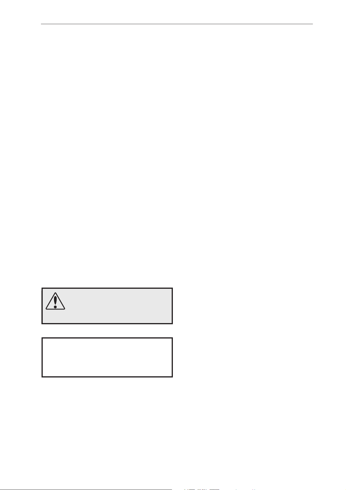
Special tools
1
4
2
5
8
97
3
6
10
13
11
14
12
4 – English
15 16
Special tools
17
18
Item Description Used for Order no.
1 Clutch tool Centrifugal clutch 502 54 16-01
2 Piston stop Locking crankshaft 502 54 15-01
3 Stop plate Locating intake gaiter 502 54 17-01
4 Fuel filter hook Withdrawing the fuel filter 502 50 83-01
5 Allen key For M5 bolts 502 50 18-01
6 Puller Frame bearing 504 90 90-02
7 Removal tool Remove seal from clutch side 502 50 55-01
8 Mandrel, sealing ring Removing crankshaft 502 54 21-01
9 Cover plate Sealing during pressure testing 502 54 11-02
10 Pressure tester Connection to cylinder 503 84 40-02
11 Feeler gauge Adjusting ignition module 502 51 34-02
12 Clamp stand Clamping the saw 502 51 02-01
13 Pressure gauge Pressurisation during testing 502 50 38-01
14 Piston fitting kit Fitting piston 502 50 70-01
15 Test plug Checking ignition module 502 71 13-01
16 Rev counter Adjusting carburettor 502 71 14-01
17 Removal tool Removing crankshaft 502 51 61-01
18 Vacuum gauge Vacuum test 502 50 37-01
19 Assembly pliers Fitting spark plug guard 502 50 06-01
20a Sleeve Fitting crankshaft 502 50 30-18
20b Shaft extension Flywheel side 502 50 30-18
20c Shaft extension Clutch side 502 50 30-18
21 Stop plate Removing crankshaft 502 54 18-01
22 Assembly tool Assembling spring, chain brake 502 50 67-01
23 Crankshaft tool Fitting crankshaft seal 502 50 30-16
19
20 b
20 c
20 a
21
22
23
English – 5
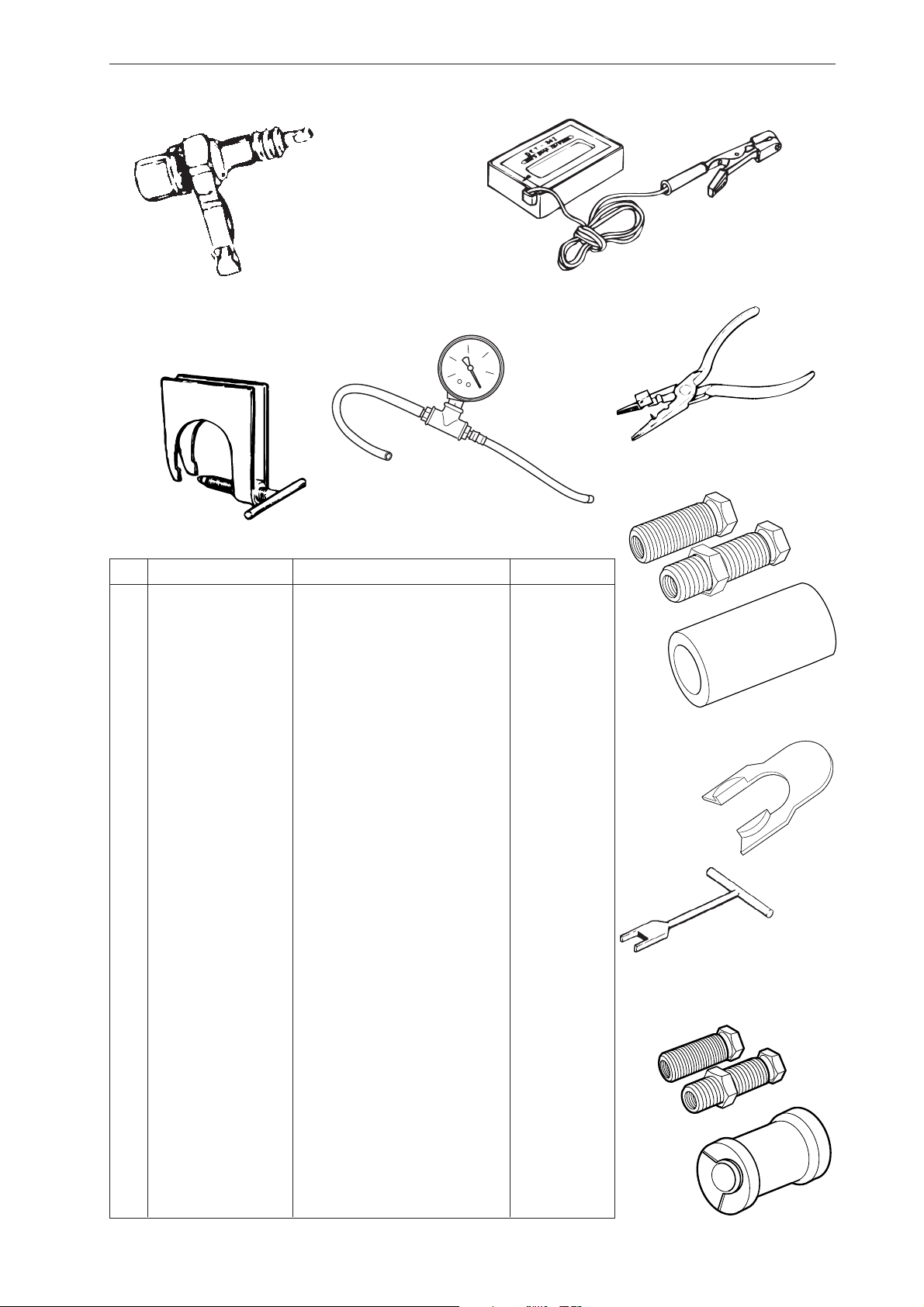
Technical data
Displacement Cylinder bore Stroke Max power/speed
cm3/cubic inches Ø mm/Ø inches mm/inches kW/hp/rpm
340: 40,8 / 2,44 40 / 1,57" 32 / 1,28" 2,0 / 2,7 / 9 000
345: 45,0 / 2,75 42 / 1,65" 32 / 1,28" 2,2 / 3,0 / 9 000
346XP/G: 45,0 / 2,75 42 / 1,65" 32 / 1,28" 2,5 / 3,4 / 9 600
350: 49,4 / 3,01 44 / 1,73" 32 / 1,28" 2,3 / 3,1 / 9 000
350 EPA: 51,7 / 3,15 45 / 1,77" 32 / 1,28" 2,3 / 3,1 / 9 000
351/G: 49,4 / 3,01 44 / 1,73" 32 / 1,28" 2,3 / 3,1 / 9 000
353/G: 51,7 / 3,15 45 / 1,77" 32 / 1,28" 2,4 / 3,3 / 9 000
Spark plug gap Ignition system Air gap Carburettor type
mm/inches mm/inches
340: 0,5 / 0,02" SEM CD 0,3 / 0,012" Walbro HDA 195
345: 0,5 / 0,02" SEM CD 0,3 / 0,012" Walbro HDA 195
346XP/G: 0,5 / 0,02" SEM CD 0,3 / 0,012" Zama C3-EL17
350: 0,5 / 0,02" SEM CD 0,3 / 0,012" Walbro HDA 195
350 EPA: 0,5 / 0,02" SEM CD 0,3 / 0,012" Zama C3-EL18
351/G: 0,5 / 0,02" SEM CD 0,3 / 0,012" Zama C3-EL17
353/G: 0,5 / 0,02" SEM CD 0,3 / 0,012" Zama C3-EL17
Effective cutting length Chain speed at Chain pitch Drive link
cm/inches max power – revs mm/inches mm/inches
m/s – rpm
340: 30-48 / 12"-19" 17,3 / 9 000 8,25 / 0,325" 1,3 / 0,050" - 1,5 / 0,058"
345: 30-48 / 12"-19" 17,3 / 9 000 8,25 / 0,325" 1,3 / 0,050" - 1,5 / 0,058"
346XP/G: 30-48 / 12"-19" 18,5 / 9 600 8,25 / 0,325" 1,3 / 0,050" - 1,5 / 0,058"
350: 30-48 / 12"-19" 17,3 / 9 000 8,25 / 0,325" 1,3 / 0,050" - 1,5 / 0,058"
350 EPA: 30-48 / 12"-19" 17,3 / 9 000 8,25 / 0,325" 1,3 / 0,050" - 1,5 / 0,058"
351/G: 30-48 / 12"-19" 17,3 / 9 000 8,25 / 0,325" 1,3 / 0,050" - 1,5 / 0,058"
353/G: 30-48 / 12"-19" 17,3 / 9 000 8,25 / 0,325" 1,3 / 0,050" - 1,5 / 0,058"
6 – English
Technical data
rpm
Idling speed Engagement speed Max. speed Spark plug
rpm rpm rpm
340: 2 700 3 800 12 500 NGK BPMR 7A, Champion RCJ 7Y
345: 2 700 3 800 12 500 NGK BPMR 7A, Champion RCJ 7Y
346XP/G: 2 700 3 800 14 200 NGK BPMR 7A, Champion RCJ 7Y
350: 2 700 3 800 13 000 NGK BPMR 7A, Champion RCJ 7Y
350 EPA: 2 700 3 800 13 000 NGK BPMR 7A, Champion RCJ 7Y
351/G: 2 700 3 800 13 000 NGK BPMR 7A, Champion RCJ 7Y
353/G: 2 700 3 800 13 000 NGK BPMR 7A, Champion RCJ 7Y
GAS
OIL
Fuel tank capacity Oil pump capacity at Oil tank capacity Automatic oil pump
Litres/US pints 8,500 rpm, Litres/US pints
ml/min
340: 0,5 / 1,05 9 0,25 / 0,53 Yes
345: 0,5 / 1,05 9 0,25 / 0,53 Yes
346XP/G: 0,5 / 1,05 5 - 12 0,28 / 0,59 Yes
350: 0,5 / 1,05 5 - 12 0,26 / 0,55 Yes
350 EPA: 0,5 / 1,05 5 - 12 0,26 / 0,55 Yes
351/G: 0,5 / 1,05 5 - 12 0,28 / 0,59 Yes
353/G: 0,5 / 1,06 5 - 12 0,28 / 0,59 Yes
Weight without bar and chain Weight with bar and chain Heated hand grips
kg / lbs kg / lbs
340: 4,7 / 10,3 5,5 / 12,1 345: 4,7 / 10,3 5,5 / 12,1 346XP: 4,8 / 10,6 5,6 / 12,2 346XPG: 4,9 / 10,8 5,7 / 12,4 Yes
350: 4,8 / 10,6 5,6 / 12,2 350 EPA: 4,8 / 10,6 5,6 / 12,2 351: 4,8 / 10,6 5,6 / 12,2 351G: 4,9 / 10,8 5,7 / 12,4 Yes
353: 5,0 / 11,0 5,8 / 12,6 353G: 5,1 / 11,2 5,9 / 13,0 Yes
English – 7
Construction and function
Carburettor
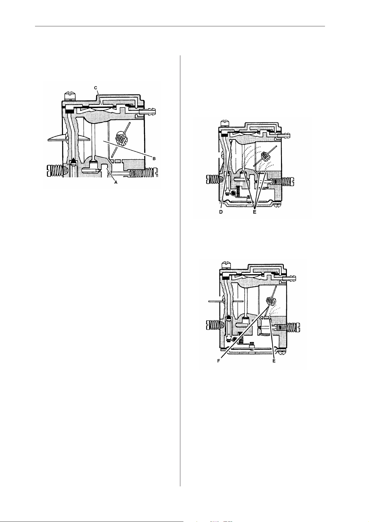
The carburettor consists of three sub-systems:
• The metering unit (A) which contains the jets
and the fuel control mechanism. This measures
out the right amount of fuel to suit the speed of
the saw and the power demand.
• The mixing unit (B) consists of the choke,
diffuser jets and throttle valve. This is where the
air and fuel are mixed to create a flammable
mixture.
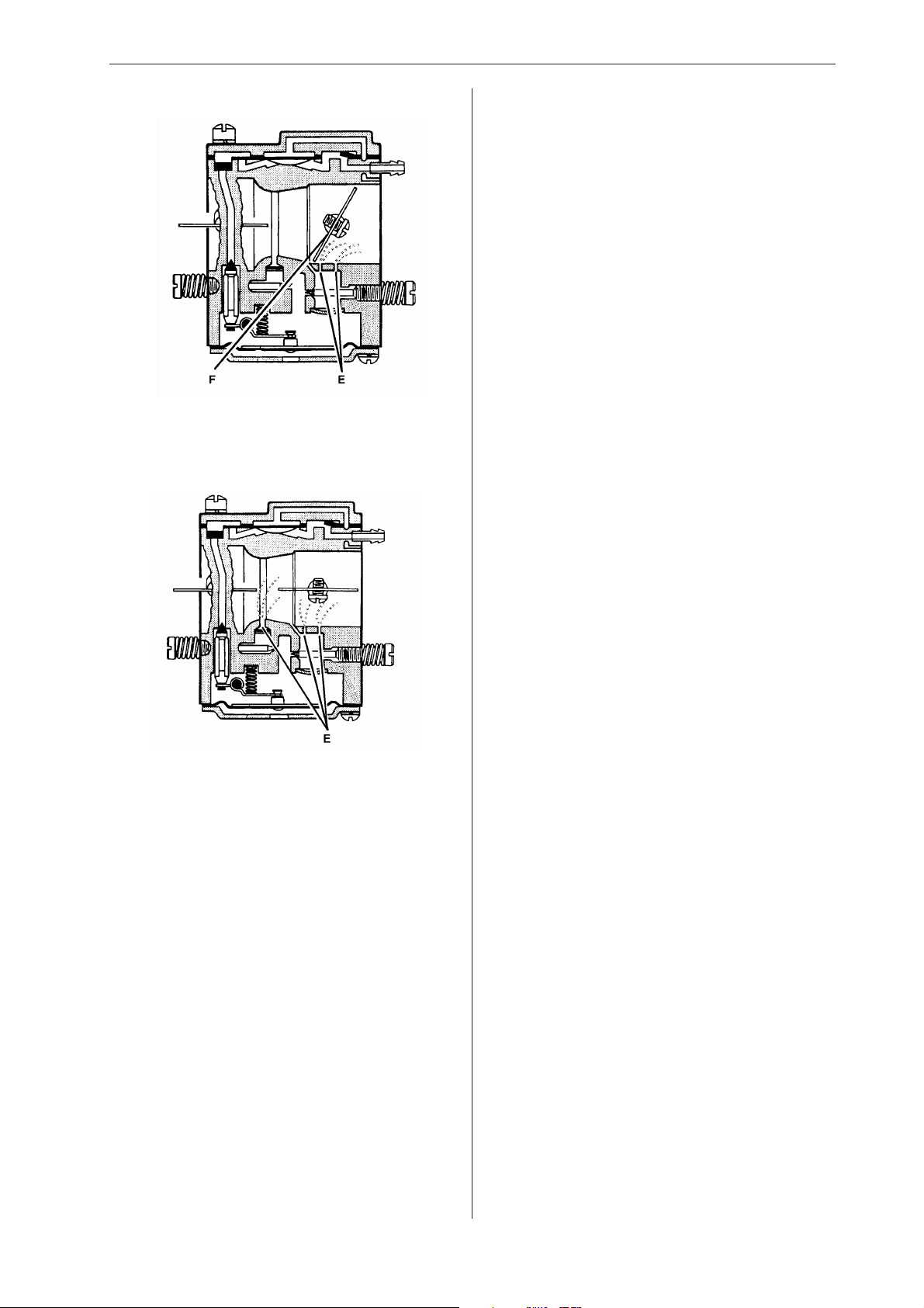
The carburettor works in different ways depending
on the setting:
• Cold start mode
• Idling mode
• Part throttle mode
• Full throttle mode
In the cold start mode the choke valve (D) is
completely closed. This increases the vacuum in
the carburettor so that fuel is sucked through the
diffuser jets faster (E).
• The pump unit (C) pumps fuel from the tank to
the metering system inside the carburettor. One
side of the pump diaphragm is connected to the
crankcase and pulses as a result of pressure
changes in the crankcase. The other side of the
diaphragm sucks in the fuel.
In idling mode the throttle valve (F) is closed. Air is
sucked through an aperture in the throttle valve
and a small amount of fuel is supplied through the
diffuser jet (E).
8 – English
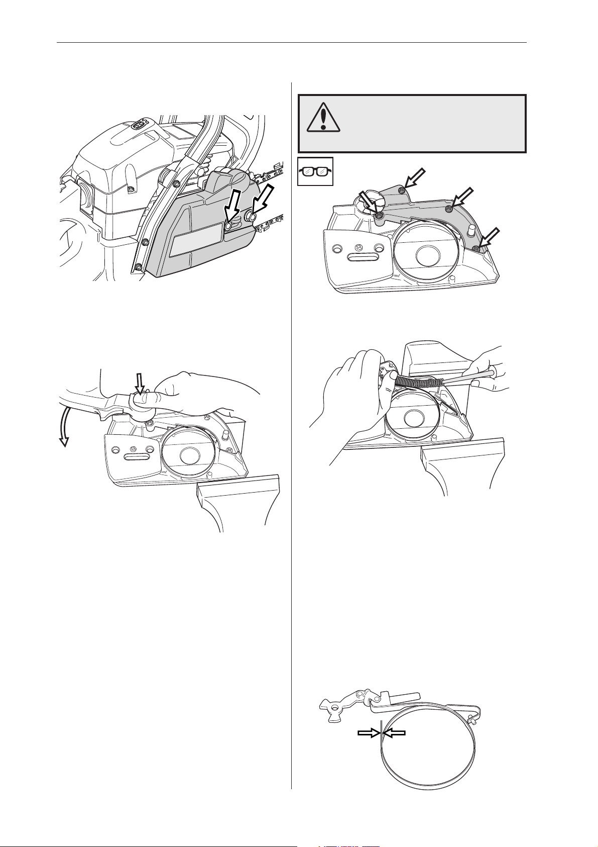
In part throttle mode the throttle valve (F) is partially open. Fuel is supplied through the diffuser jets
(E).
Construction and function
In full throttle mode both valves are open and fuel
is supplied through all the diffuser jets (E).
English – 9

Troubleshooting
The various faults that can affect a chainsaw are divided into four groups. In each group the likely symptoms are given on the left and possible causes are listed on the right. The most likely faults are given first,
and so on.
Starting
Difficulty starting
Carburettor
leaking fuel
Flooding when
engine not
running
Idling (low rpm)
Will not idle
Idling too rich
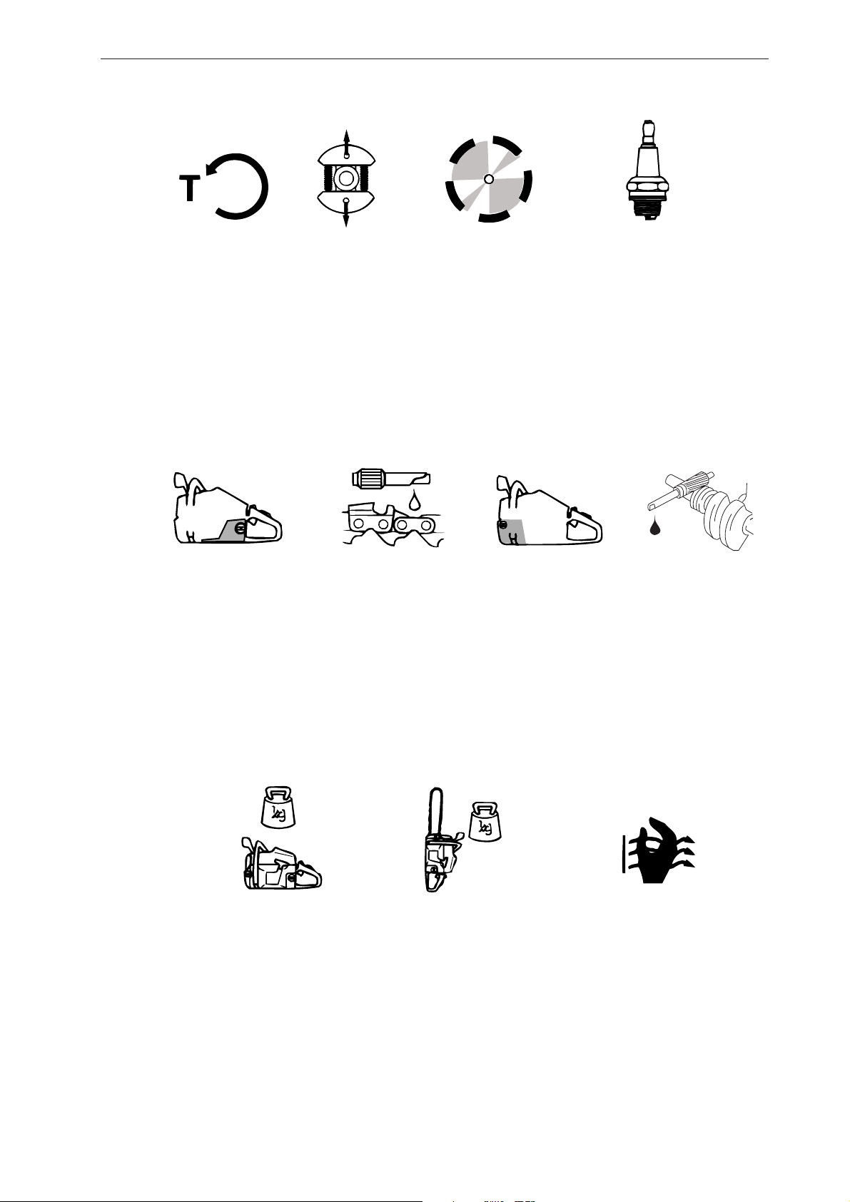
Adjust L screw
Air filter blocked
Choke not working
Worn choke pivot
Worn choke valve
Fuel filter blocked
Fuel line blocked
Piston ring seized
Blocked impulse channel
Loose or faulty fuel pipe
Hole in diaphragm
Worn needle valve
Needle valve assembly sticking
Needle valve set too high
Leak in metering system (air
or fuel)
Loose cover on carburettor
pump side
Worn needle valve
Needle valve set too high
Needle valve assembly sticking
Adjust L screw
Leaking air intake hose
(rubber)
Loose carburettor mounting
bolts
Loose or faulty fuel hose
Fuel filter blocked
Fuel line blocked
Fuel tank vent blocked
Throttle valve pivot stiff
Throttle pushrod sticking
Defective throttle return spring
Bent throttle stop
Faulty diffuser jet
Adjust L screw
Worn needle valve
Needle valve set too high
Worn needle valve lever
Leaking control diaphragm/
cover plate
Needle valve assembly
sticking
Idling (low rpm) (cont.)
Idles when L
screw closed
Idling uneven
L screw requires
constant
adjustment
Too much fuel at
idling
Worn needle valve
Leaking control diaphragm/
cover plate
Needle valve assembly sticking
Worn needle valve lever
Faulty diffuser jet
Fuel filter blocked
Fuel line blocked
Leaking air intake hose (rubber)
Loose carburettor mounting
bolts
Worn throttle valve pivot
Loose throttle valve screw
Worn throttle valve
Needle valve assembly
sticking
Leak in metering system (air
or fuel)
Metering system centre knob
is worn
Hole in diaphragm
Leaking control diaphragm/
cover plate
Crankcase leaking
Fuel line blocked
Needle valve set too high
Needle valve assembly sticking
Leak in metering system (air
or fuel)
Leaking control diaphragm/
cover plate
Faulty diffuser jets
Crankcase leaking
Needle valve set too high
Needle valve assembly sticking
Metering system damaged
Worn needle valve
Leaking control diaphragm/
cover plate
Metering system incorrectly
assembled
10 – English

Troubleshooting
High rpm
Will not run at
full throttle
Low power
Will not “fourstroke”
Adjust H screw
Blocked air filter
Blocked fuel tank vent
Blocked fuel filter
Fuel line blocked
Loose or damaged fuel hose
Impulse channel leaking
Impulse channel blocked
Loose cover on carburettor pump
side
Faulty pump diaphragm
Leaking air intake hose (rubber)
Loose carburettor mounting bolts
Needle valve set too low
Metering system damaged
Metering system incorrectly
assembled
Leaking control diaphragm/cover
plate
Needle valve assembly sticking
Blocked silencer
Adjust H screw
Blocked fuel tank vent
Blocked fuel filter
Impulse channel leaking
Impulse channel blocked
Loose cover on carburettor pump
side
Faulty pump diaphragm
Blocked air filter
Needle valve assembly sticking
Leak in metering system (air or fuel)
Metering system incorrectly
assembled
Loose diaphragm rivet
Hole in diaphragm
Leaking control diaphragm/cover
plate
Blocked fuel tank vent
Blocked fuel filter
Fuel line blocked
Loose or damaged fuel hose
Impulse channel leaking
Impulse channel blocked
Loose cover on carburettor pump
side
Faulty pump diaphragm
Leaking air intake hose (rubber)
Loose carburettor mounting bolts
Needle valve set too low
Leak in metering system (air or fuel)
Metering unit incorrectly assembled
Loose diaphragm rivet
Hole in diaphragm
Leaking control diaphragm/cover
plate
Acceleration and retardation
Does not
accelerate
Engine stalls
when throttle
released
Over rich
acceleration
Adjust L screw
Adjust H screw
Blocked air filter
Blocked fuel tank vent
Blocked fuel filter
Fuel line blocked
Loose or damaged fuel hose
Impulse channel blocked
Loose cover on carburettor pump
side
Faulty pump diaphragm
Leaking air intake hose (rubber)
Loose carburettor mounting bolts
Needle valve set too low
Metering system incorrectly
assembled
Needle valve assembly sticking
Faulty diffuser jets
Blocked silencer
Adjust L screw
Adjust H screw
Faulty pump diaphragm
Needle valve set too high
Needle valve assembly sticking
Faulty diffuser jets
Adjust L screw
Adjust H screw
Blocked air filter
Faulty pump diaphragm
Faulty diffuser jets
Troubleshooting methods
In addition to the faults described in the above
table, trouble shooting can be carried out on
specific components or sub-systems of the
chainsaw. The various procedures are described in
the relevant chapters, see the contents page, as
follows:
• Checking the operation of the chain brake
• Measuring the resistance of the stop plate
• Pressure testing the carburettor
• Pressure testing the decompression valve
• Pressure testing the cylinder
English – 11
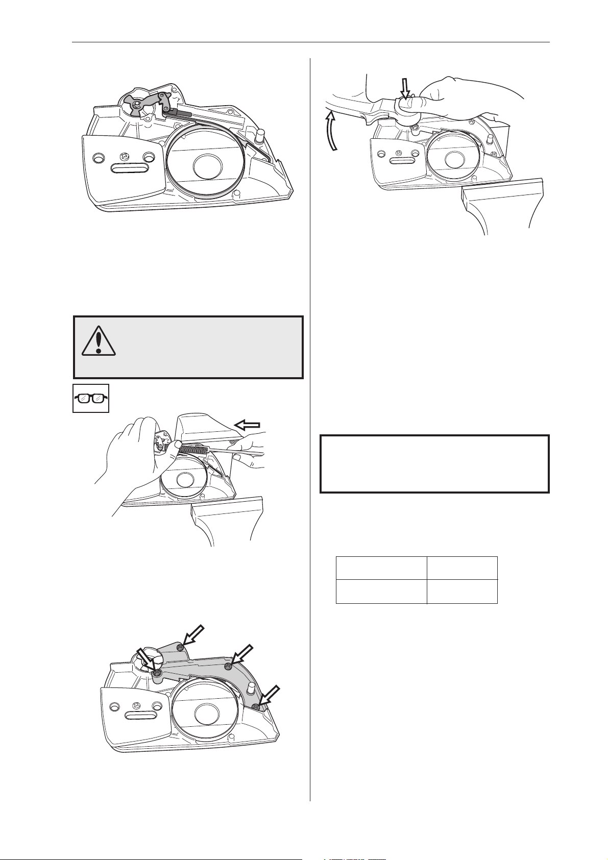
Chain brake – dismantling
Repair instructions
3
1
Disengage the brake by pushing the kickback
guard backwards. Unscrew the guide bar bolts and
remove the clutch cover, chain and guide bar.
2
WARNING!
Make sure the spring does not fly
out and cause injury. Wear eye
protection.
Remove the screws and carefully remove the cover
from the chain brake spring.
4
Grip the clutch cover carefully in a vice. Release
the brake spring by using the kickback guard from
the saw as a tool. Engage it with the brake mechanism and turn anticlockwise to activate the brake.
Place one hand over the spring and insert a small
screwdriver between the bottom end of the spring
and the clutch cover. Carefully prise the spring
upwards so that it slides onto the screwdriver shaft.
Cleaning and inspection
• Clean and inspect all parts carefully. If there are
any cracks or other defects replace the damaged
parts with new ones. Always use original parts.
• Measure the thickness of the chain brake band.
It must be no less than 0.6 mm at any point.
• Lubricate the elbow joint with grease.
min 0,6 mm
12 – English
Repair instructions
Chain brake – reassembly
1
Bolt the elbow joint to the brake band and tighten
to a torque of 1–1.5 Nm.
Locate the elbow joint and connected brake band
in their recesses in the clutch cover. Lubricate the
recess for the spring with grease.
2
WARNING!
Make sure the spring does not fly
out and cause injury. Wear eye
protection.
4
Tension the brake spring by using the kickback
guard from the saw as a tool. Engage it with the
brake mechanism and turn clockwise to release
the brake.
5
Turn the chain tensioner anticlockwise as far as it
will go.
Refit:
• guide bar
Grip the clutch cover in a vice. Compress the
spring with special tool 502 50 67-01 and push it
down with your thumb.
3
• chain
• clutch cover
NOTE!
After completing the repair the chain
brake must be tested as described below.
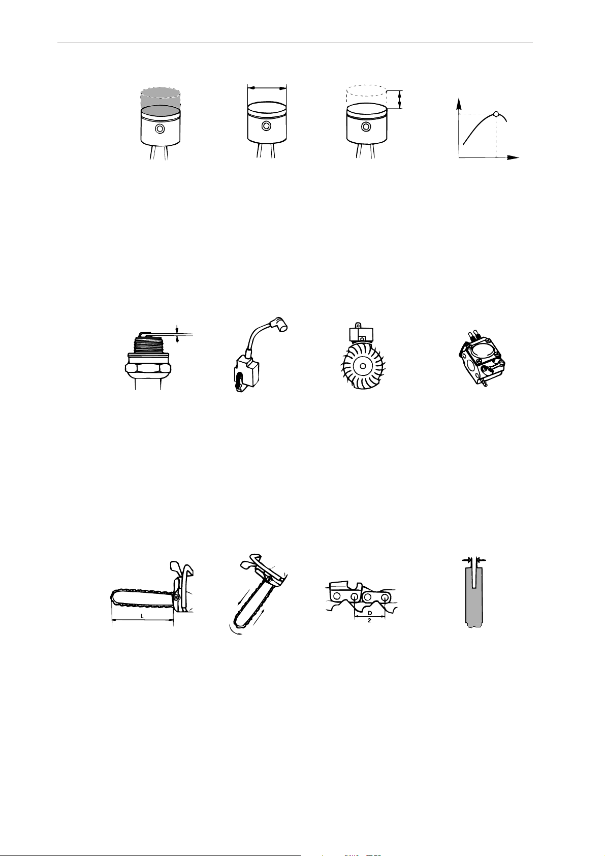
Operating test:
The engine must not be running during the test.
Guide bar length Height
38cm/15" 50 cm/20"
• Hold the chainsaw over a firm surface. The
height of the guide bar above the surface is
given in the table above.
• Let go of the front handle and let the chainsaw
fall towards the surface.
• When the guide bar hits the surface the chain
brake must engage.
Fit the cover over the chain brake spring, tightening
the screws to a torque of 1–1.5 Nm.
English – 13
Repair instructions
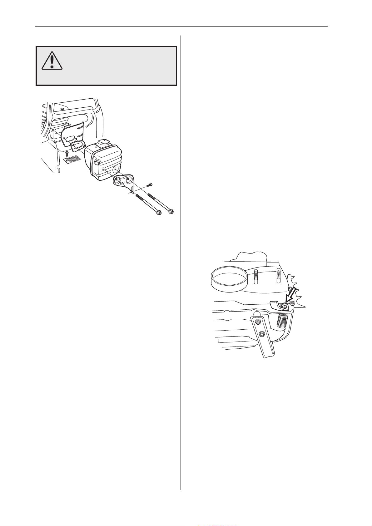
Silencer – removal
WARNING!
Do not touch the silencer until it
has cooled down, otherwise you
may burn yourself.
1
Silencer – refitting
1
If the saw is equipped with a spark arrestor mesh
this should be fitted first.
2
Refit
• cooling plate
• gasket
• silencer, tighten bolts to a torque of 8–10 Nm.
• silencer support
• cylinder cover
3
Run the saw for at least 1 minute, then retighten
the silencer bolts to 8–10 Nm.
Chain catcher – replacement
If the chain catcher is worn it must be replaced with
a new one.
Remove the cylinder cover, silencer support,
silencer, gasket and cooling plate.
2
If the saw is fitted with a spark arrestor mesh this
must also be removed.
Cleaning and inspection
Clean and inspect all parts carefully. If there are
any cracks or other defects replace the damaged
parts with new ones.
The spark arrestor mesh is best cleaned with a
wire brush. If the mesh is damaged it must be
replaced.
If the mesh is blocked the saw will overheat and
this will cause damage to cylinder and piston.
Never use the saw with a silencer that is in poor
condition. Always use original parts.
1
Release the brake by pushing the kickback guard
backwards. Undo the guide bar bolts and remove
the clutch cover, chain and guide bar.
2
Remove the chain catcher and replace it with a
new one. Check that the vibration damping spring
locates correctly against the crankcase when you
bolt the new chain catcher in position.
A worn (damaged) chain catcher on 340, 345 or
350 can be replaced with the same chain catcher
as 346XP, 351 and 353 (see figure above).
14 – English
3
Turn the chain tensioner anticlockwise as far as it
will go.
Refit:
• guide bar
• chain
• clutch cover
Repair instructions
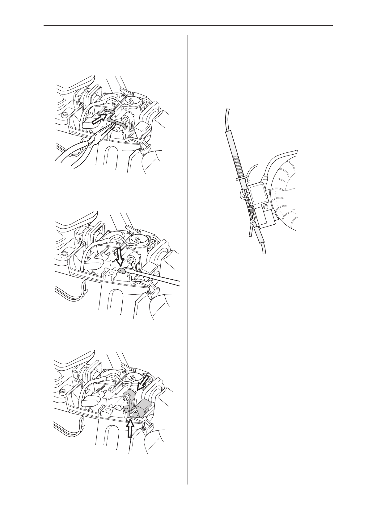
Stop switch – removal
1
Remove the cylinder cover and air filter.
2
Disconnect both leads from the stop plate and stop
switch. Remove the stop plate by carefully sliding it
over the lug on the front mounting.
3
Cleaning and inspection
Clean and inspect all parts carefully. If there are
any cracks or other defects replace the damaged
parts with new ones. Always use original parts.
Stop switch – resistance measurement
Clean the mating surfaces and check the resistance as follows:
Carefully prise the carburettor assembly off the lefthand rubber mounting using a small screwdriver.
4
Measure the resistance by connecting a multimeter
to the ignition coil. NOTE! The switch must be in
the “on” position to give the correct reading.
The resistance must not be higher than 0.2 ohm
when the switch is in the on position.
Carefully prise the stop switch’s upper mounting off
the air filter holder while lifting the switch to release
it from the lower mounting.
English – 15
 Loading...