

Humminbird HELIX 9, HELIX 10 Operation Manual
HELIX 9 and HELIX 10
Operations Guide
532400-1EN_A

THANK YOU!
Thank you for choosing Humminbird®, the #1 name in marine electronics. Humminbird has built its reputation by designing and
manufacturing top quality, thoroughly reliable marine equipment. Your Humminbird is designed for trouble-free use in even the
harshest marine environment. We encourage you to read this manual carefully in order to get the full benefit from all the features
and applications of your Humminbird product.
Contact Humminbird Customer Service at humminbird.com or call 1-800-633-1468.
WARNING! This device should not be used as a navigational aid
to prevent collision, grounding, boat damage, or personal injury.
When the boat is moving, water depth may change too quickly to
allow time for you to react. Always operate the boat at very slow
speeds if you suspect shallow water or submerged objects.
WARNING! The electronic chart in your Humminbird unit is an
aid to navigation designed to facilitate the use of authorized
government charts, not to replace them. Only official
government charts and notices to mariners contain all of the
current information needed for the safety of navigation, and the
captain is responsible for their prudent use.
WARNING! Humminbird is not responsible for the loss of data
files (waypoints, routes, tracks, groups, recordings, etc.) that
may occur due to direct or indirect damage to the unit’s
hardware or software. It is important to back up your control
head’s data files periodically. Data files should also be saved to
your PC before restoring the control head defaults or updating
the software. See the following sections of your Humminbird
manual: Manage Screen Snapshots and Recordings and
Manage your Navigation Data: Import/Export Navigation Data.
WARNING! Disassembly and repair of this electronic unit should
only be performed by authorized service personnel. Any
modification of the serial number or attempt to repair the original
equipment or accessories by unauthorized individuals will void the
warranty.
WARNING! This product contains chemicals known to the State of
California to cause cancer and birth defects or other reproductive
harm.
NOTE: Do NOT leave the control head SD card slot cover open.
The slot cover should always be closed to prevent water damage
to the unit.
NOTE: Some features discussed in this manual require a
separate purchase, and some features are only available on
international models. Every effort has been made to clearly
identify those features. Please read the manual carefully in
order to understand the full capabilities of your model.
NOTE: The illustrations in this manual may not look the same as
your product, but your unit will function in a similar way.
NOTE: To purchase accessories for your control head, visit our
Web site at humminbird.com or contact Humminbird Customer
Service at 1-800-633-1468.
NOTE: The procedures and features described in this manual are
subject to change without notice. This manual was written in
English and may have been translated to another language.
Humminbird is not responsible for incorrect translations or
discrepancies between documents.
NOTE: Product specifications and features are subject to change
without notice.
NOTE: Humminbird verifies maximum stated depth in saltwater
conditions, however actual depth performance may vary due to
transducer installation, water type, thermal layers, bottom
composition, and slope.
ROHS STATEMENT: Product designed and intended as a fixed
installation or part of a system in a vessel may be considered beyond
the scope of Directive 2002/95/EC of the European Parliament and of
the Council of 27 January 2003 on the restriction of the use of certain
hazardous substances in electrical and electronic equipment.
ATTENTION INTERNATIONAL CUSTOMERS: Products sold in the U.S.
are not intended for use in the international market. Humminbird
international units provide international features and are designed
to meet country and regional regulations. Languages, maps, time
zones, units of measurement, and warranty are examples of
features that are customized for Humminbird international units
purchased through our authorized international distributors.
To obtain a list of authorized international distributors, please visit
our Web site at humminbird.com or contact Humminbird Customer
Service at (334) 687-6613.
2

ENVIRONMENTAL COMPLIANCE STATEMENT: It is the intention of Johnson Outdoors Marine Electronics, Inc. to be a responsible corporate citizen,
operating in compliance with known and applicable environmental regulations, and a good neighbor in the communities where we make or sell
our products.
WEEE DIRECTIVE: EU Directive 2002/96/EC “Waste of Electrical and Electronic Equipment Directive (WEEE)” impacts most distributors, sellers,
and manufacturers of consumer electronics in the European Union. The WEEE Directive requires the producer of consumer electronics to take
responsibility for the management of waste from their products to achieve environmentally responsible disposal during the product life cycle.
WEEE compliance may not be required in your location for electrical & electronic equipment (EEE), nor may it be required for EEE designed and
intended as fixed or temporary installation in transportation vehicles such as automobiles, aircraft, and boats. In some European Union member
states, these vehicles are considered outside of the scope of the Directive, and EEE for those applications can be considered excluded from the
WEEE Directive requirement.
This symbol (WEEE wheelie bin) on product indicates the product must not be disposed of with other household refuse. It must be disposed
of and collected for recycling and recovery of waste EEE. Johnson Outdoors Marine Electronics, Inc. will mark all EEE products in accordance
with the WEEE Directive. It is our goal to comply in the collection, treatment, recovery, and environmentally sound disposal of those
products; however, these requirements do vary within European Union member states. For more information about where you should
dispose of your waste equipment for recycling and recovery and/or your European Union member state requirements, please contact your dealer
or distributor from which your product was purchased.
360 Imaging®, AUTOCHART®, ChartSelect™, Contour XD™, Down Imaging®, DualBeam PLUS™, Fish ID+™, HELIX™, HumminbirdPC™, Humminbird®, LakeMaster®, Real
Time Sonar™, RTS™, RTS Window™, Side Imaging®, SI™, Structure ID™, SwitchFire®, UniMap™, WhiteLine™, X-Press™ Menu, aretrademarked by or registered trademarks
of Johnson Outdoors Marine Electronics, Inc.
Adobe, Acrobat, Adobe PDF, and Reader are either registered trademarks or trademarks of Adobe Systems Incorporated in the United States and/or other countries.
Baekmuk Batang, Baekmuk Dotum, Baekmuk Gulim, and Baekmuk Headline are registered trademarks owned by Kim Jeong-Hwan.
Navionics® Gold, HotMaps™, and HotMaps™ Premium, Navionics® Classic Charts, and Platinum™ Cartography are trademarked by or registered trademarks of Navionics
S.p.A.
© 2015 Johnson Outdoors Marine Electronics, Inc. All rights reserved.
345


TABLE OF CONTENTS
Warnings 2
Introduction 7
How to Use this Manual 7
Getting Started 8
HELIX Control Head 16
Menu System Overview 18
Open an X-Press Menu . . . . . . . . . . . . . . . . . . . . . . . . . . . . . . . . . . .18
Open the Main Menu . . . . . . . . . . . . . . . . . . . . . . . . . . . . . . . . . . . . .18
Select a Menu . . . . . . . . . . . . . . . . . . . . . . . . . . . . . . . . . . . . . . . . . .19
Change a Menu Setting . . . . . . . . . . . . . . . . . . . . . . . . . . . . . . . . . .19
Tips for Using the Menu System . . . . . . . . . . . . . . . . . . . . . . . . . .20
Change the User Mode (Normal or Advanced) . . . . . . . . . . . . . .21
Close the Menu System . . . . . . . . . . . . . . . . . . . . . . . . . . . . . . . . . .21
Views 22
Display a View . . . . . . . . . . . . . . . . . . . . . . . . . . . . . . . . . . . . . . . . . . .22
Show your Favorite Views . . . . . . . . . . . . . . . . . . . . . . . . . . . . . . . .23
Save a View to a VIEW SHORTCUT Key . . . . . . . . . . . . . . . . . . . . .23
Display Digital Readouts . . . . . . . . . . . . . . . . . . . . . . . . . . . . . . . . .24
Combo Views . . . . . . . . . . . . . . . . . . . . . . . . . . . . . . . . . . . . . . . . . . .28
Sonar Overview (Sonar, DI, SI) 29
Display a Side Imaging View On-Screen 67
Understand the Side Imaging View . . . . . . . . . . . . . . . . . . . . . . . .68
Customize the Side Imaging View . . . . . . . . . . . . . . . . . . . . . . . . .70
Adjust Settings While you Fish . . . . . . . . . . . . . . . . . . . . . . . . . . . .72
Review Side Imaging History and Zoom In/Zoom Out . . . . . . . .76
Navigation in Side Imaging Views . . . . . . . . . . . . . . . . . . . . . . . . .78
Manage Screen Snapshots and Recordings 80
Chart Overview 87
Display a Chart View On-Screen . . . . . . . . . . . . . . . . . . . . . . . . . .88
Select a Chart Source . . . . . . . . . . . . . . . . . . . . . . . . . . . . . . . . . . .89
Customize the Bird’s Eye View . . . . . . . . . . . . . . . . . . . . . . . . . . . .94
Customize the Chart View . . . . . . . . . . . . . . . . . . . . . . . . . . . . . . . .95
Display Humminbird LakeMaster
Contour Lines and Depth Ranges . . . . . . . . . . . . . . . . . . . . . . .99
Change the Chart Orientation and Motion Mode . . . . . . . . . . .101
Navigation Overview 104
Navigation Alarms Overview . . . . . . . . . . . . . . . . . . . . . . . . . . . . .106
Man Overboard (MOB) Navigation . . . . . . . . . . . . . . . . . . . . . . . .107
Waypoints . . . . . . . . . . . . . . . . . . . . . . . . . . . . . . . . . . . . . . . . . . . . .109
Routes . . . . . . . . . . . . . . . . . . . . . . . . . . . . . . . . . . . . . . . . . . . . . . . .118
Tracks . . . . . . . . . . . . . . . . . . . . . . . . . . . . . . . . . . . . . . . . . . . . . . . . .123
Search . . . . . . . . . . . . . . . . . . . . . . . . . . . . . . . . . . . . . . . . . . . . . . . .126
Set up Sonar (Sonar, DI, SI) 31
Display a Sonar View On-Screen 35
Understand the Sonar Views . . . . . . . . . . . . . . . . . . . . . . . . . . . . . .36
Customize the Sonar View . . . . . . . . . . . . . . . . . . . . . . . . . . . . . . . .37
Adjust Sonar Display Settings . . . . . . . . . . . . . . . . . . . . . . . . . . . .40
Adjust Settings While you Fish . . . . . . . . . . . . . . . . . . . . . . . . . . . .44
Compare Sonar Beams (Split Sonar View) . . . . . . . . . . . . . . . . .48
Review Sonar History and Zoom In/Zoom Out . . . . . . . . . . . . . .49
Navigation in Sonar Views . . . . . . . . . . . . . . . . . . . . . . . . . . . . . . . .53
Display a Down Imaging View On-Screen 56
Down Imaging Overview . . . . . . . . . . . . . . . . . . . . . . . . . . . . . . . . . .57
Customize the Down Imaging View . . . . . . . . . . . . . . . . . . . . . . . .58
Adjust Settings While you Fish . . . . . . . . . . . . . . . . . . . . . . . . . . . .60
Review Down Imaging History and Zoom In/Zoom Out . . . . . . .63
Navigation in Down Imaging Views . . . . . . . . . . . . . . . . . . . . . . . .65
Manage your Navigation Data 128
Manage Waypoints . . . . . . . . . . . . . . . . . . . . . . . . . . . . . . . . . . . . .131
Manage Routes . . . . . . . . . . . . . . . . . . . . . . . . . . . . . . . . . . . . . . . .135
Manage Tracks . . . . . . . . . . . . . . . . . . . . . . . . . . . . . . . . . . . . . . . . .142
Manage Groups . . . . . . . . . . . . . . . . . . . . . . . . . . . . . . . . . . . . . . . .144
Search and Organize . . . . . . . . . . . . . . . . . . . . . . . . . . . . . . . . . . .148
Import/Export Navigation Data . . . . . . . . . . . . . . . . . . . . . . . . . .150
Delete All Navigation Data and Reset . . . . . . . . . . . . . . . . . . . . .150
Manage your Control Head 151
Update Software 155
Maintenance 156
Troubleshooting 157
Specifications 159
Contact Humminbird 170

6
INTRODUCTION
The instructions in this manual describe the HELIX 9 and HELIX 10 control head operations. For an overview of functions, see the
Operations Summary Guide included with your product.
Build your Network: Some of the features shown in this manual require a separate purchase. Radar, AIS, Compass/Heading Sensor,
Ethernet, i-Pilot Link, etc. require a separate purchase. To install each accessory, use the installation guide provided with it, or
download the guide from our Web site at humminbird.com.
Register and Update: As you build your Humminbird network, it is important to register your products and keep your software up to
date. Visit our Web site at humminbird.com to set up an account, update control head and accessory software, and purchase
additional equipment. Also, see Update Software in this manual for more information.
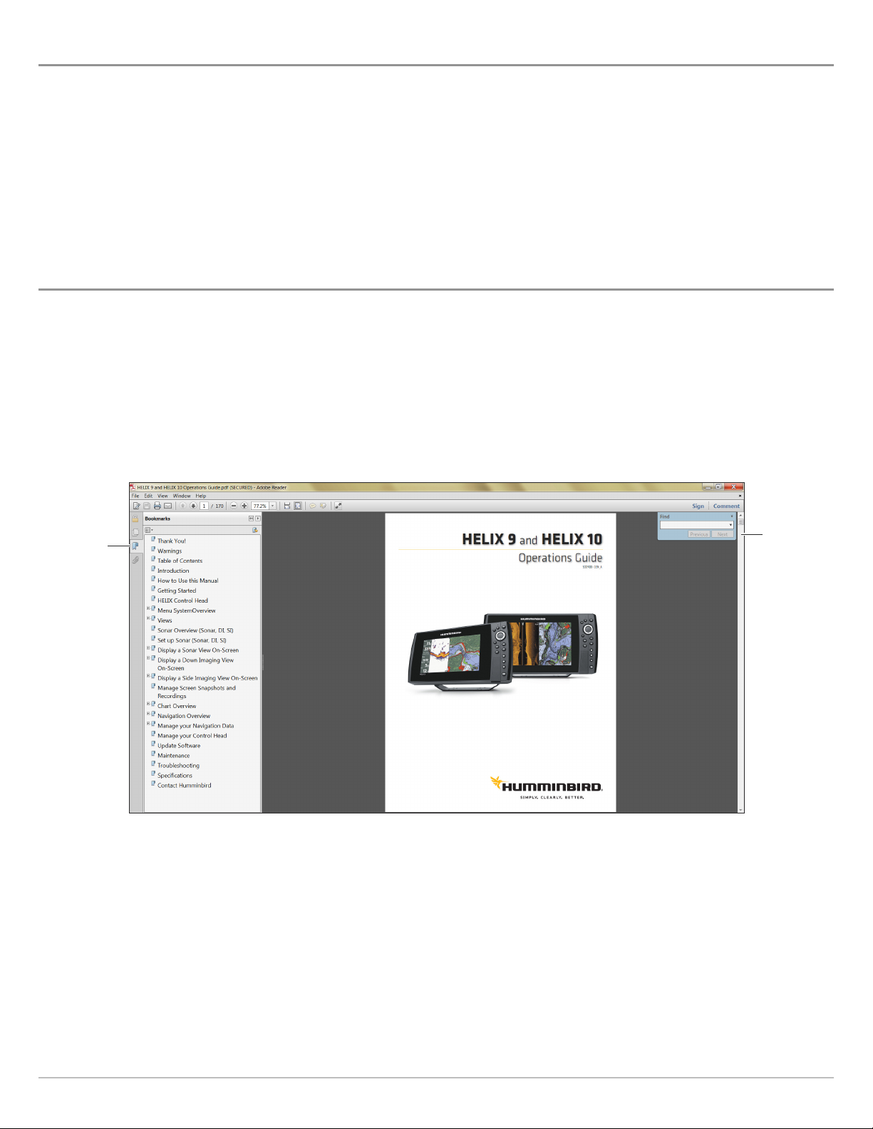
HOW TO USE THIS MANUAL
To open, read, and print the Adobe PDF files, you will need Adobe Reader software installed on your computer. To download the free
Adobe Reader software to your computer, visit http://get.adobe.com/reader/.
Jump to a Section: Click a section name in the Bookmarks panel. Bookmarks can be expanded and collapsed by clicking on the plus
(+) or minus (-) icons.
Search for Words or Phrases: Press and hold the Ctrl F keys on your PC keyboard. Type the word(s) into the text box.
Using the Manual
bookmarks
panel
search for
key words
(Ctrl + F)
7
Introduction
GETTING STARTED
The procedures in this section describe how to get started with your control head. Some of the settings in this section are a onetime set up, and other settings (such as checking the GPS reception) you will use each time you hit the water.
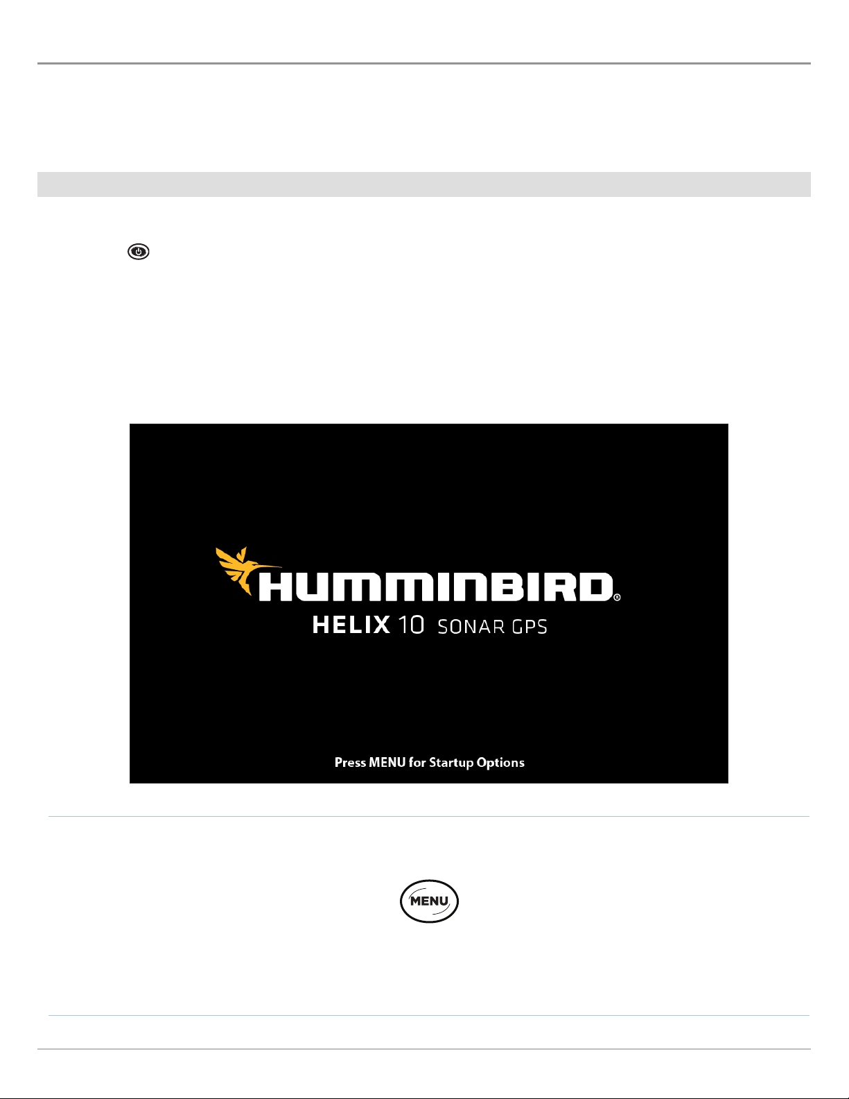
Power On
Follow the instructions below to power on your Humminbird control head.
1. Press the POWER key.
2. When the Title screen is displayed, press the MENU key.
Title Screen
Getting Started
Press the MENU key
8
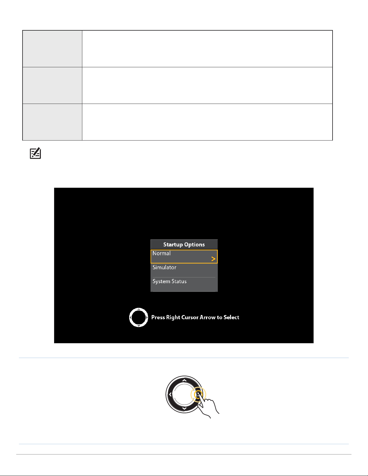
3. Select Normal. Press the RIGHT Cursor key.
Normal mode is required for on-the-water operation. If a functioning transducer is
Normal
connected to the control head, Normal will be selected automatically, and your control head
can be used on the water.
To learn how to use your control head, select Simulator. You can save menu settings and
Simulator
navigation data in Simulator mode (see Chart Overview and Navigation Overview for more
information).
To view system information for software version, GPS reception, and accessory connections,
System Status
select System Status. See Check Accessory Connections and Check GPS Reception for more
information.
NOTE: If you wait too long to select a start-up option, the system will start the mode that is already highlighted. If your control head
goes into Demonstration mode, please note that menu settings cannot be saved in this mode (see Manage your Control Head).
Starting Normal Mode for on-the-water Operations
Press the
RIGHT Cursor key
9
Getting Started
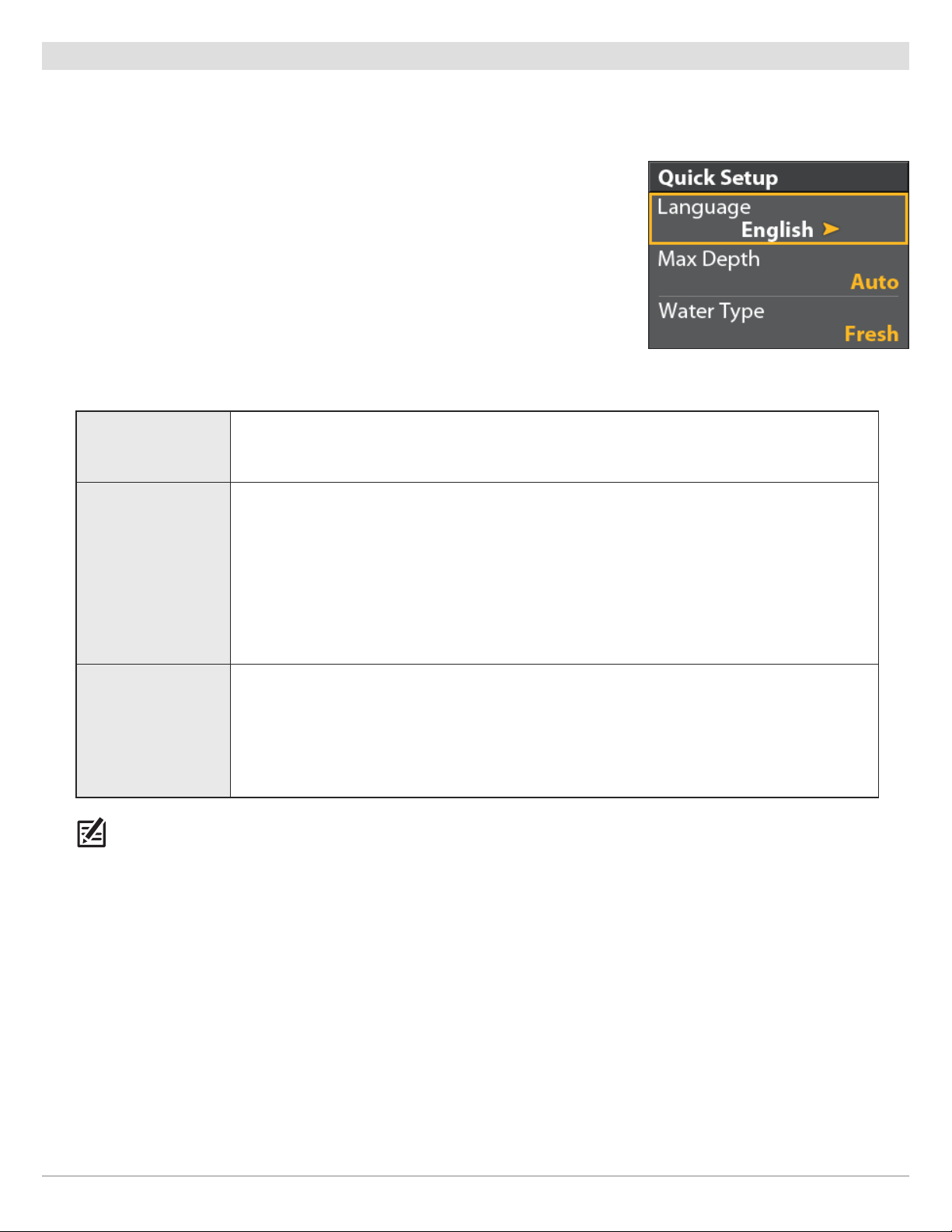
Quick Setup
If this is the first time the unit has been powered on (after installation or after restoring defaults), the Quick Setup menu will display.
Set up the Control Head
1. Use the Cursor Control key to change the settings.
2. Close: Press the EXIT key.
Language The available languages are determined by your Humminbird model.
Set the maximum depth of the body of water. When Max Depth is set to Auto, the control
head will acquire bottom readings as needed (within the capabilities of the unit). When Max
Max Depth
Depth is set to match your water maximum depth, the control head will not attempt to
acquire sonar data below that depth, so more detail will be shown on the display.
Quick Setup Menu
Side Imaging units default to the Side Imaging range setting if the SI Range is set deeper
than the Max Depth. See Side Imaging Overview for more information.
Water Type affects the accuracy of deep water depth readings and configures the control
Water Type
NOTE: To change the Max Depth and the Water Type after the initial Setup, see Set up Sonar.
head for operation in fresh or salt water.
In salt water, you can also choose the shallow or deep setting. If the depth is more than 330
ft (100 m), select Salt (deep).
Getting Started
10
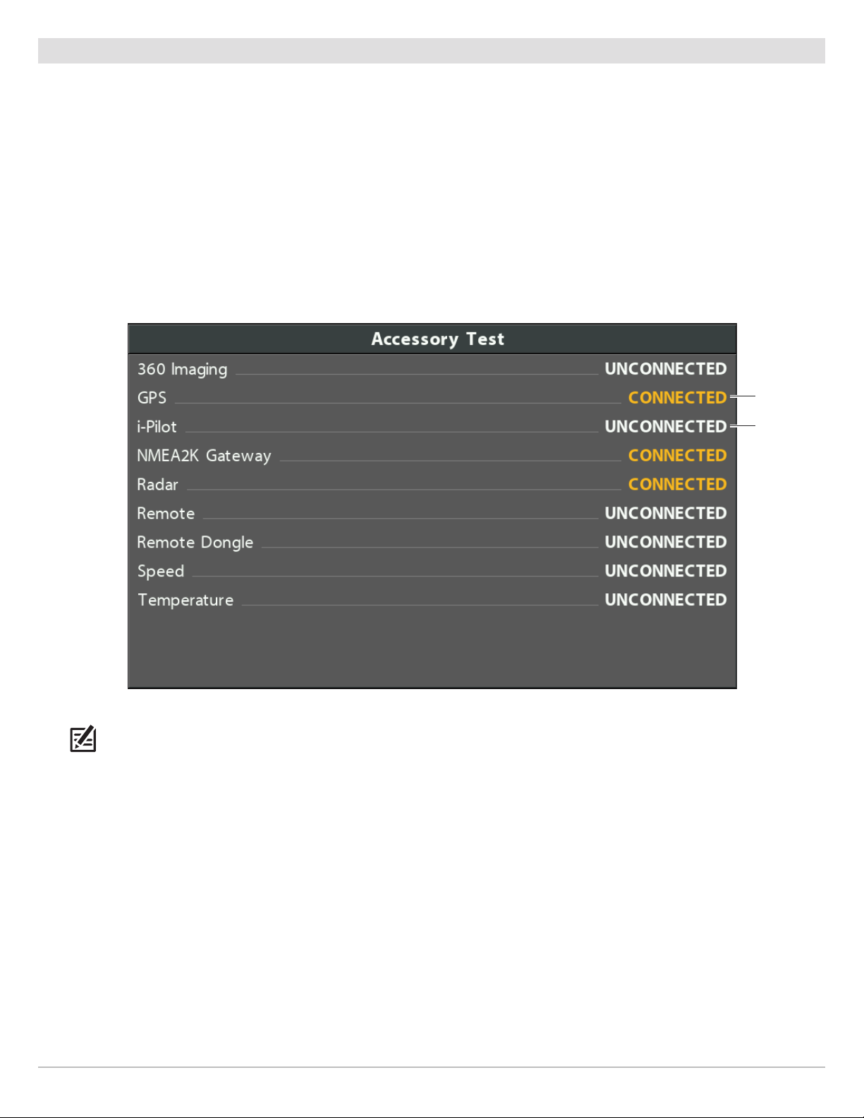
Check Accessory Connections
If you’ve connected other separate-purchase equipment to the control head network, such as AIS, Compass/Heading Sensor, Radar,
i-Pilot Link, 360 Imaging, and more, use these instructions to confirm the equipment is detected and communicating with the
control head.
1. Press and hold the VIEW key.
2. Select System > Accessory Test.
Confirm all accessories are listed as Connected. If you have a temp/speed wheel, the wheel must move for it to be detected.
Unconnected: If an accessory is listed as Unconnected, check the cable and power connections to confirm they are secure and
powered on. Review the installation guide that was included with your accessory to confirm it is installed correctly.
Confirming Accessories are Detected
connected
unconnected
(not detected
by the control
head)
NOTE: The menus for installed accessories are typically included in the Accessory tab in the Main Menu. See your accessory guide
for details.
11
Getting Started
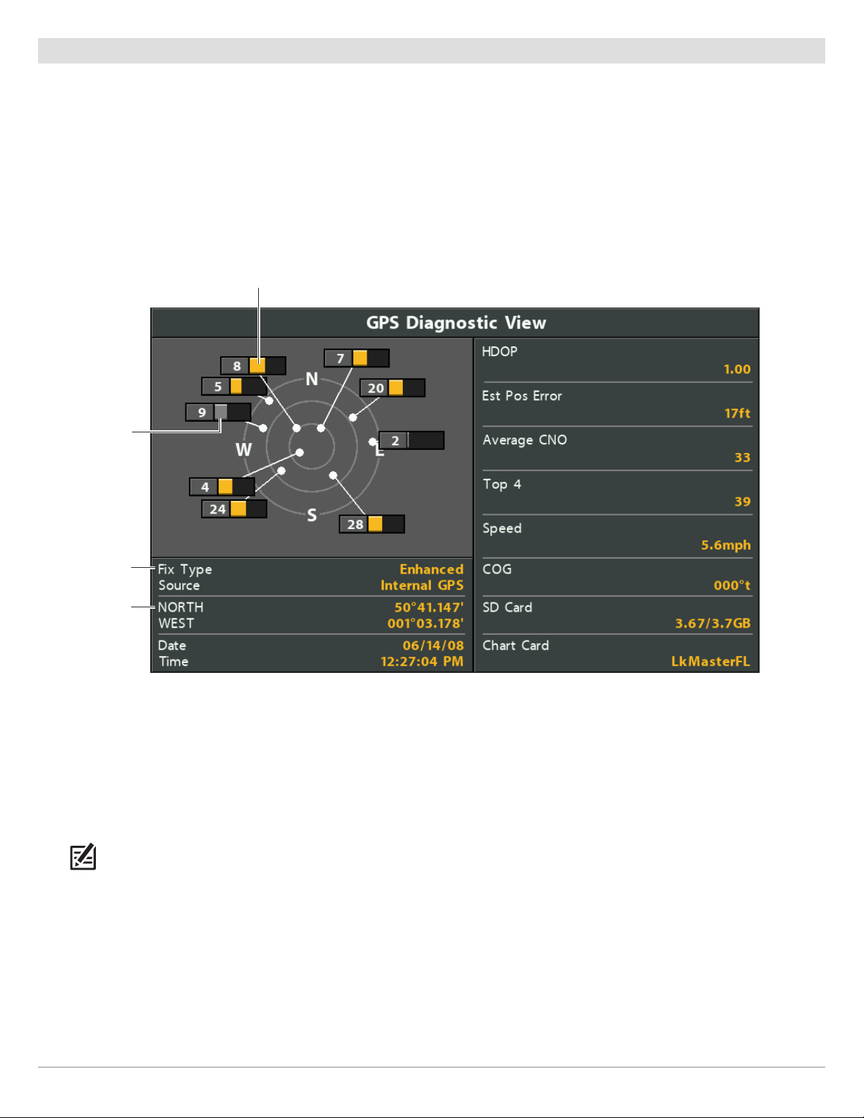
Check GPS Reception
Use the instructions in this section to confirm the control head has GPS reception.
1. Press and hold the VIEW key.
2. Select System > GPS Diagnostic View.
Confirm Fix Type is shown as Enhanced or 3D.
Confirm that the latitude/longitude position readout is displayed.
Reviewing GPS Reception
active satellite signal strength (yellow)
monitored satellite
signal strength
(gray)
fix type shown as
enhanced
latitude/longitude
position
GPS Reception: The sky chart displays the satellite number and signal strength bar.
GPS Fix Type: reported as No Fix, 2D Fix, 3D Fix, or Enhanced. An Enhanced Fix has been augmented using information from
WAAS, EGNOS, or MSAS.
HDOP (the Horizontal Dilution of Precision): a GPS system parameter which depends on the current satellite configuration.
HDOP is used to calculate the Estimated Position Error.
NOTE: To manually change your GPS source, see Manage your Control Head.
Getting Started
12
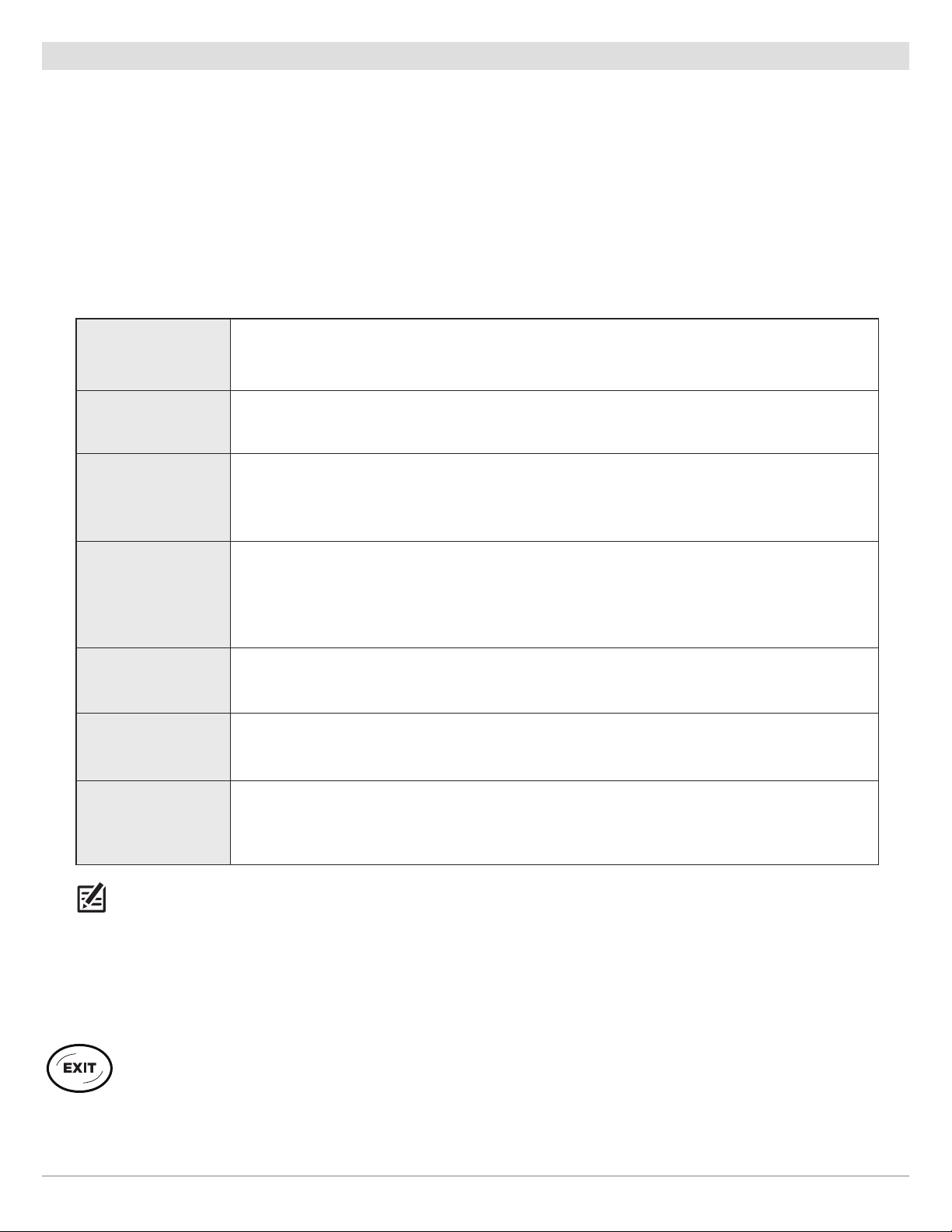
Set Alarms
When an alarm is turned on, an alert will sound or display on the control head to indicate the threshold has been exceeded.
Turn on Alarms and Adjust Settings
1. Main Menu: Press the MENU key twice.
OR
To open the Main Menu from a System View, press the MENU key once.
2. Select the Alarms tab.
3. Select an alarm menu. Press the RIGHT or LEFT Cursor keys to adjust the threshold.
Depth Alarm
Fish ID Alarm
Low Battery Alarm
Temp. Alarm
Off Course Alarm
Arrival Alarm
The alarm will be triggered when the depth becomes equal to or less than the menu setting.
Transducer required.
The alarm will be triggered when a fish is detected based on the menu setting. See Adjust Sonar
Display Settings for more information.
The alarm will be triggered when the input battery votage is equal to or less than the menu
setting. The battery must be connected to the control head. See your control head installation
guide for more information.
The alarm will be triggered when the water temperature detected by the control head is equal
to the temp alarm setting. Input from the built-in transducer temperature sensor or a
temperature accessory is required.
Sets how far the boat can move off course during navigation before an alarm will be triggered.
GPS required. See Navigation Overview for more information.
Sets how close the boat must be to the destination waypoint before the alarm will be triggered.
GPS required. See Navigation Overview for more information.
Drift Alarm
NOTE: The available alarms are determined by the connected equipment, so your control head may provide more or less options
than the information shown here. If there are accessories installed, review the accessory guide for alarm information.
4. Close: Press the EXIT key twice.
Sets how far the boat can move from its anchored position outside the drift alarm perimeter
before an alarm will be triggered. GPS required. See Navigation Overview for more information.
Exit an Alarm
If an alarm is triggered during control head operation, you can close it or silence it using these instructions.
1. Press any key on the control head.
13
Getting Started

Reset the Triplog
The Triplog includes the timer for elapsed time, distance traveled since last reset, and average speed. Use the following instructions
to reset the triplog. To display the Triplog as a digital readout, see Views: Display Digital Readouts.
1. Main Menu: Press the MENU key twice.
2. Select the Setup tab.
3. Select Triplog Reset.
4. Press the RIGHT Cursor key.
5. Follow the on-screen prompts.
Turn on/off Sound
Use the instructions in this section to choose the category of sounds you want to hear from your control head.
1. Main Menu: Press the MENU key twice.
2. Select the Setup tab.
3. Select Sound Control.
4. Select All Sounds or Alarms only.
To receive a sound alert from an alarm, Sound Control must be set to All Sounds or Alarms Only.
Change the Alarm Tone: Select the Alarms tab > Alarm Tone.
Change the User Mode
The User Mode determines how many menu options are displayed in the menu system. Select Normal to see fewer menu options
that are used more often. Select Advanced to see all the menu options available in the menu system.
Instructions in this manual marked with Main Menu (Advanced User Mode) indicate that the menu system User Mode must be set
to Advanced for the selected menu to be shown. If you do not see the menu in the system, change the User Mode to Advanced. See
Menu System Overview for details.
1. Main Menu: Press the MENU key twice.
2. Select the Setup tab.
3. Select User Mode.
4. Select Normal or Advanced.
Set up Sonar
If you’ve installed an accessory transducer, or to refine your sonar settings, see Set up Sonar for details.
Set up Chart Preferences
If you’ve installed an SD map card, see Chart Overview to set up the chart source.
Getting Started
14

Change Units of Measurement
Use the instructions in this section to change the units of measurement format. You can also change the time and date format,
language, and installation offsets from this menu. See Manage your Control Head for more information.
1. Main Menu: Press the MENU key twice.
2. Select the Setup tab.
3. Select Units - Depth, Units - Distance, etc., and select each unit setting as needed.
4. Close: Press the EXIT key.
Adjust the Backlight
1. Press the POWER key.
2. Select Light.
3. Adjust the Backlight setting from Dim to 10 (brightest).
Power Off
Use the following instructions to power off your control head. You should save the current track before powering off, and your control
head should always be turned off using the POWER key.
Save the Current Track
1. Chart X-Press Menu: With a Chart View displayed on-screen, press the MENU key once.
2. Select Save Current Track.
3. Press the RIGHT Cursor key.
Power Off
1. Press and hold the POWER key.
15
Getting Started
HELIX CONTROL HEAD
Control Head Keys
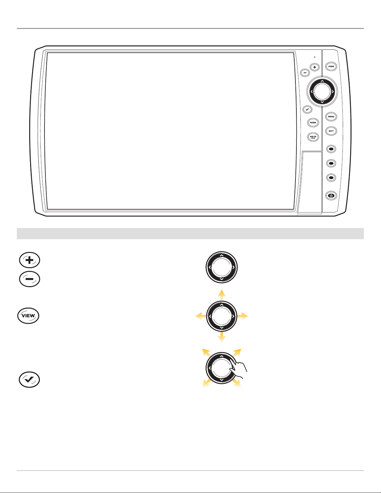
ZOOM IN (+)/ZOOM OUT (–) KEYS
Press the ZOOM keys to change the scale of the view.
For a closer view, press the ZOOM IN (+) key. For a
wider view, press the ZOOM OUT (-) key. You can also
magnify the cursor selection.
VIEW KEY
Press and hold the VIEW key to open the Views
X-Press menu, or press the VIEW key repeatedly until
the view you want to use is displayed on the screen.
Press the EXIT key to display the previous view. See
Views for details.
CHECK/INFO KEY
In the Chart View, press the CHECK/INFO key to see
information about the cursor position or about
objects located near the cursor position. If the cursor
is not active, the Chart Info submenu will open. See
Navigation Overview for details.
CURSOR CONTROL KEY
(LEFT, RIGHT, UP, or DOWN Cursor keys)
Press the arrows on the Cursor Control key
to move through the menu system, select
menus, and change or activate menu
settings. See Menu System Overview for
details.
Also, press any arrow on the Cursor Control
key to move the cursor on the view.
To move the cursor diagonally, press in
between the arrows.
The Control Head
16
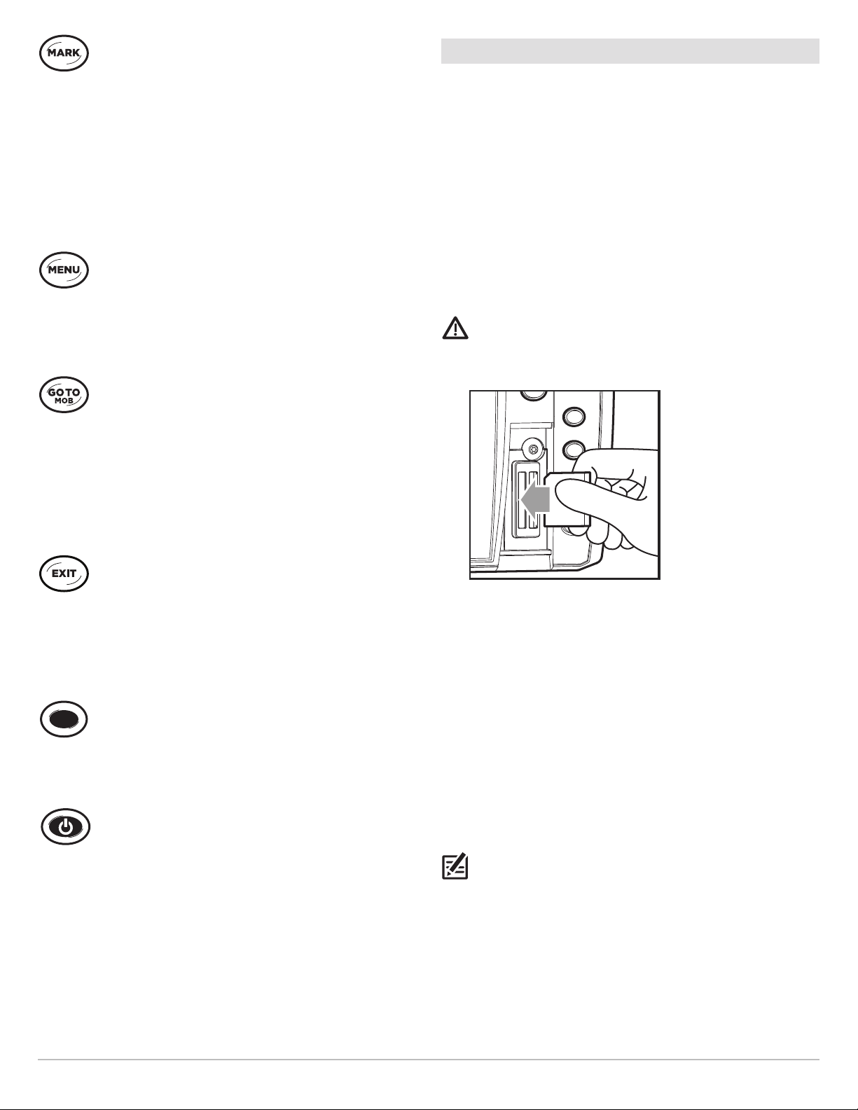
MARK KEY
SD Card Slot(s)
Press the MARK key to save a waypoint at the boat
position. If the cursor is active, the waypoint will be
marked at the cursor position. See Navigation
Overview for details.
If Screen Snapshot is turned on, a screen snapshot
will be created with the waypoint, and the screen
snapshot will be saved to the installed SD Card. See
Screen Snapshot for details.
MENU KEY
To open the X-Press Menu for the on-screen view and
operation mode, press the MENU key once. To open
the Main Menu, press the MENU key twice. See Menu
System Overview for details.
GOTO/MAN OVERBOARD (MOB)KEY
With an active cursor, press the GOTO key once to
create a waypoint and start navigation towards that
waypoint. If the cursor is not active, press the GOTO
key, and choose from the saved navigation data. To
start Man Overboard navigation, press and hold the
GOTO key. See Navigation Overview and Man
Overboard (MOB) Navigation for details.
The SD card slot on your control head can be used with an SD
card (separate purchase required) to update software, add
detailed charts to your control head, import/export navigation
data, and save sonar recordings and screen snapshots.
Software Updates: For details, see Update Software.
Add Maps: see Chart Overview.
Import/Export Navigation data: See Manage your
Navigation Data.
Sonar Recordings and Screen Snapshots: See Manage
Screen Snapshots and Recordings.
CAUTION! Before the control head software is updated or
restored to system defaults, export your navigation data (see
Update Software).
EXIT KEY
Press the EXIT key to close a menu, close a dialog box,
turn off an alarm, or exit Cursor mode.
Also, press the EXIT key to scroll through the View
Rotation in reverse order. See Views for details.
VIEW SHORTCUT KEY
Press and hold a VIEW SHORTCUT key to save a
shortcut to the on-screen view. You can save one view
on each VIEW SHORTCUT key. See Views for details.
POWER KEY
Press the POWER key to power on the control head.
To power off, press and hold the POWER key.
During operation, press the POWER key. The backlight
can be adjusted from this menu. You can also turn
on/off Sonar and change the view background color.
Insert the SD card with the
label facing to the left
Insert an SD Card
1. Remove the SD card slot cover.
2. Position the SD card so that the label faces to the left.
3. Insert the card into the slot until it clicks into place.
4. Replace the slot cover so it is secure.
5. Remove: Press the card into the slot and then release it.
The card will eject. Pull the card carefully from the slot.
NOTE: Do not leave the SD card slot cover open. The slot
cover should always be closed to prevent water damage to
the unit.
17
The Control Head
MENU SYSTEM OVERVIEW
x 2
x1
The menu system provides menu options that are determined by the operations mode, on-screen view, and connected accessories.
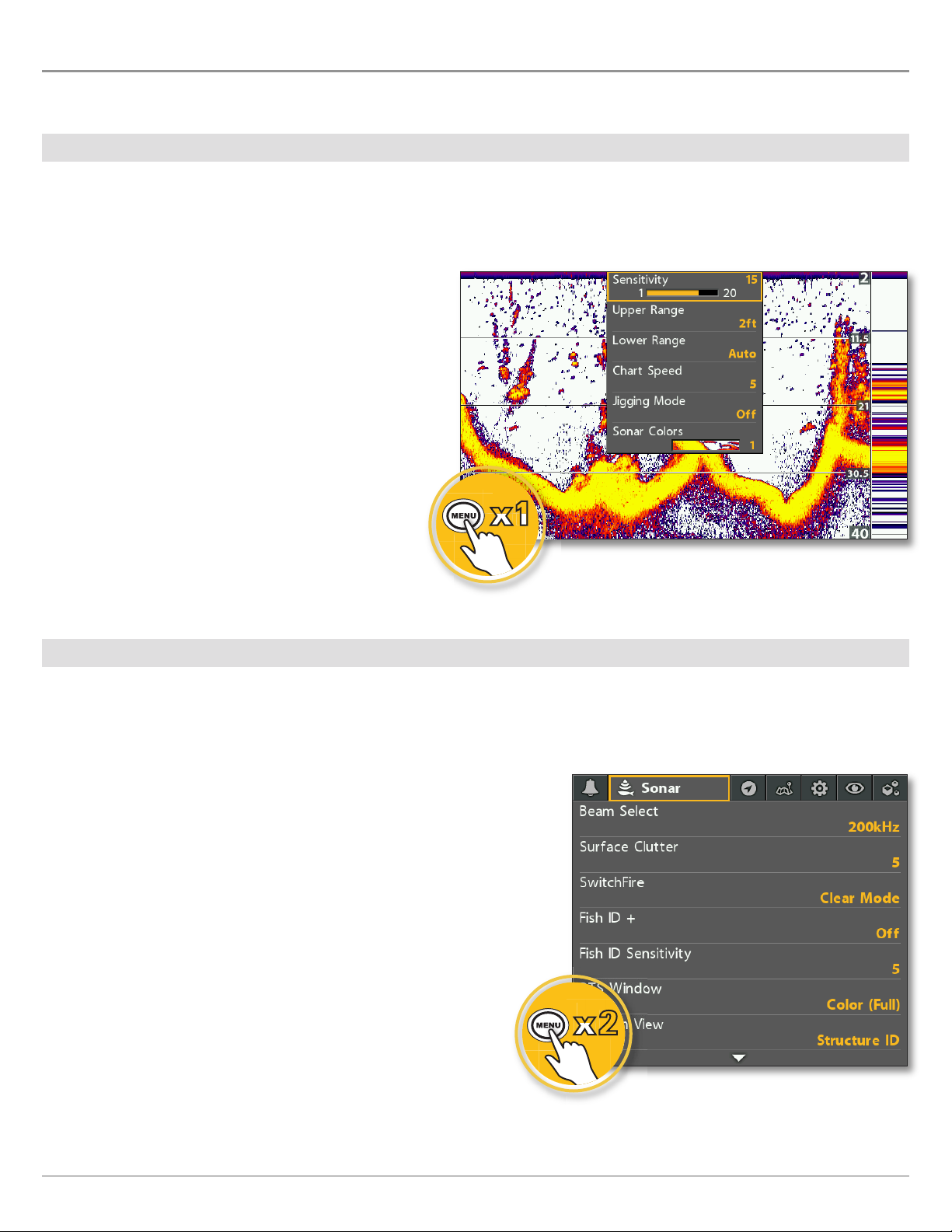
Open an X-Press Menu
The X-Press Menu displays menus that are related to the on-screen view and the operations mode (such as navigation). In this
illustration, the Sonar X-Press Menu is displayed because the Sonar View is displayed on the screen.
Open the X-Press Menu
1. Press the VIEW key repeatedly until the view you want
is displayed on-screen.
2. Press the MENU key once.
Opening the Sonar X-Press Menu
Open the Main Menu
The main menu is divided into tabbed categories (Alarms, Sonar, Navigation, Chart, Setup, Views, and Accessories). The available
tabs and menus are determined by your model and the connected accessories.
Open the Main Menu
1. Press the MENU key twice.
Menu System Overview
Opening the Main Menu
18
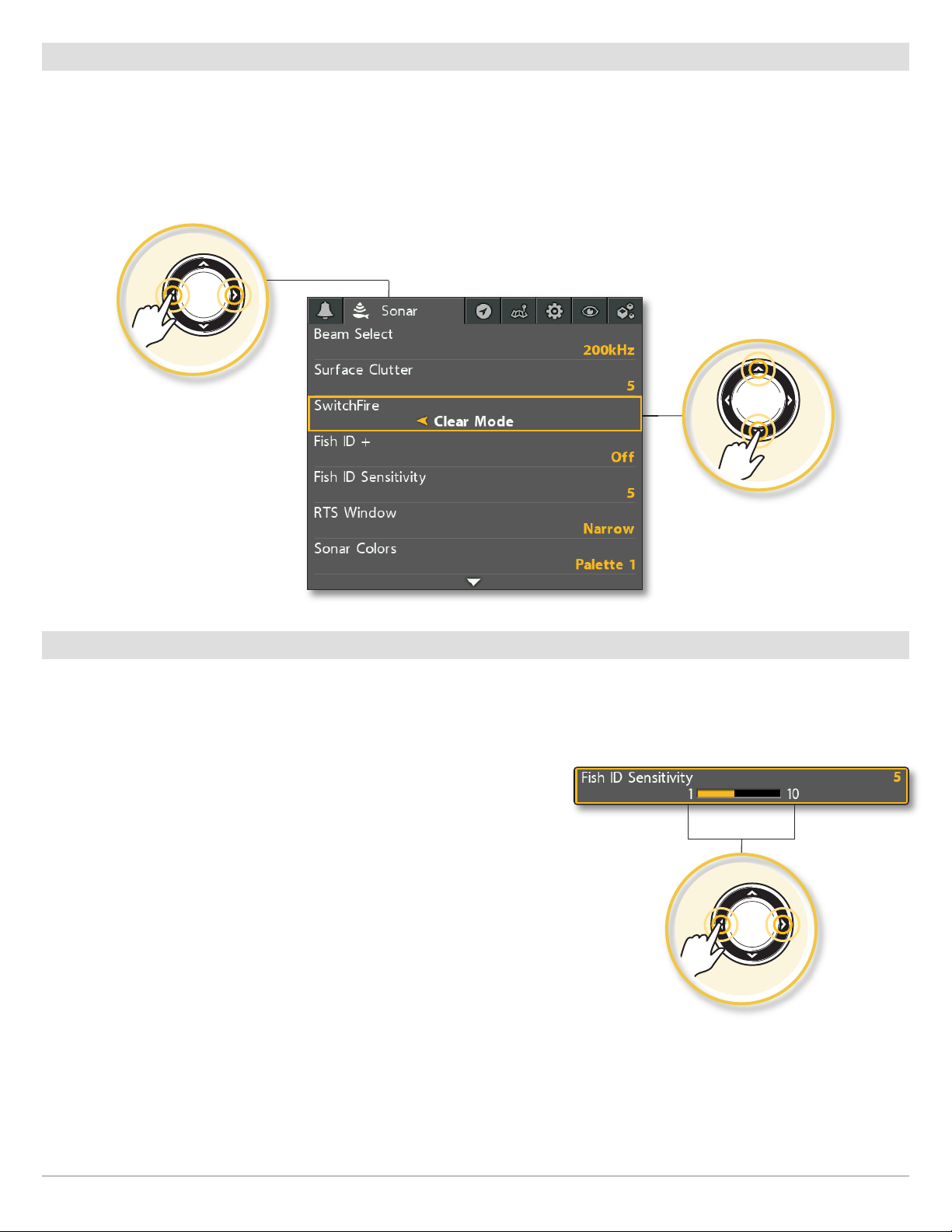
Select a Menu
Use the Cursor Control key to select a menu in the Main Menu or X-Press Menu.
Select a Tab (Main Menu) Select a Menu
1. Press the RIGHT or LEFT Cursor keys. 1. Press the DOWN or UP Cursor keys.
Select a Tab
Select a Menu
Change a Menu Setting
Use the Cursor Control key to change menu settings or start an action. When you change a menu setting, the view will update
immediately.
Adjust a Menu Setting
1. Press the RIGHT or LEFT Cursor keys.
Change a Menu Setting
19
Menu System Overview
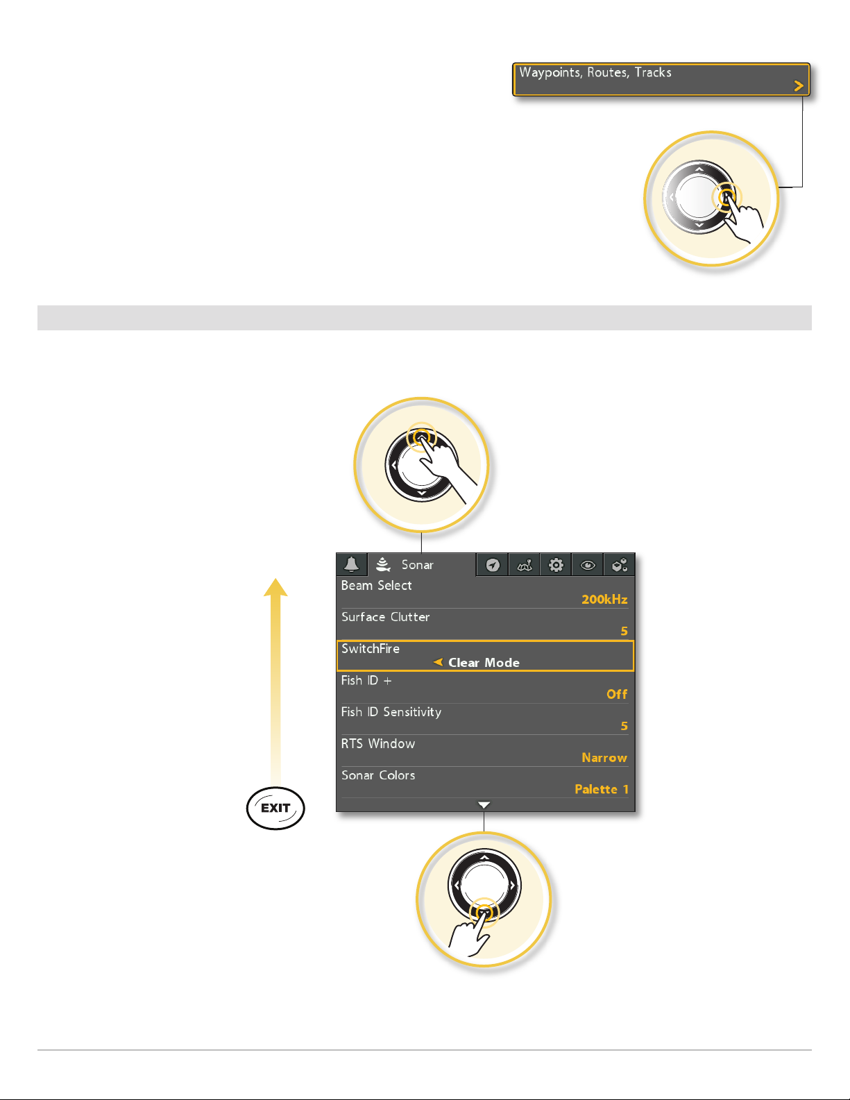
Start an Action/Open a Submenu
1. If a menu has a right arrow on it, press the RIGHT Cursor key to start the
action or open the submenu.
Tips for Using the Menu System
You can move through the menu system quickly using the following tips.
Jump to the Bottom of the Tab
Start an Action or Open a Submenu
Menu System Overview
Jump to the Top of the Tab
See More Menus
20
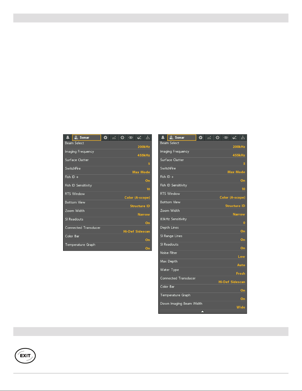
Change the User Mode (Normal or Advanced)
The User Mode determines how many menus are shown in the menu system. Select Normal to see fewer menus that are used more
often. Select Advanced to see all the menus available in the menu system.
Main Menu (Advanced User Mode): Instructions in this manual marked with Main Menu (Advanced User Mode) indicate that the
menu system User Mode must be set to Advanced for the selected menu to be shown. If you do not see the menu in the system,
change the User Mode to Advanced.
Change the User Mode
1. Main Menu: Press the MENU key twice.
2. Select the Setup tab.
3. Select User Mode.
4. Select Normal or Advanced.
Main Menu: Sonar Tab
(User Mode set to Normal)
Main Menu: Sonar Tab
(User Mode set to Advanced)
Close the Menu System
Use the EXIT key to go back through the menu system or close the menu system.
Back: Press the EXIT key to close the current menu and go back one level in the menu system.
Close: Press the EXIT key repeatedly until the menu system is closed.
21
Menu System Overview
VIEWS
The HELIX control head has many options to display data on-screen, and the data can be displayed in a variety of ways. There are
also several ways to quickly display a view on-screen.
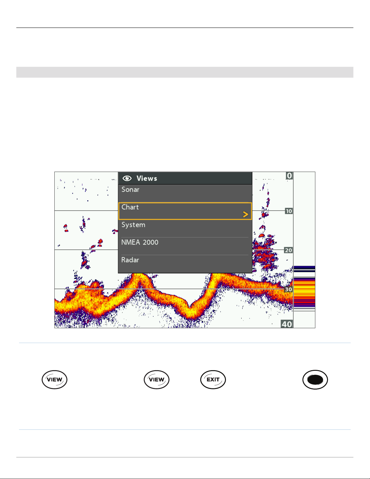
Display a View
The available views on your control head are determined by the model you’ve purchased and the connected transducer.
Display a View from the Views X-Press Menu
1. Press and hold the VIEW key.
2. Select a view category. Press the RIGHT Cursor key.
3. Select a view. Press the RIGHT Cursor key.
Selecting a View to Display on the Screen
Press and Hold to Open
the Views X-Press Menu
Views
OR OR
Forward: Press to go
to the Next View
Back: Press to go to
the Previous View
22
Press to Display
a Saved View
Display the Next/Previous View
Next View: Press the VIEW key repeatedly until the view you want is displayed on-screen.
Previous View: Press the EXIT key repeatedly until the view you want is displayed on-screen.
Display a Saved View
1. Press a VIEW SHORTCUT key.
You can save one view on each VIEW SHORTCUT key. See Save a View to a VIEW SHORTCUT key for more information.
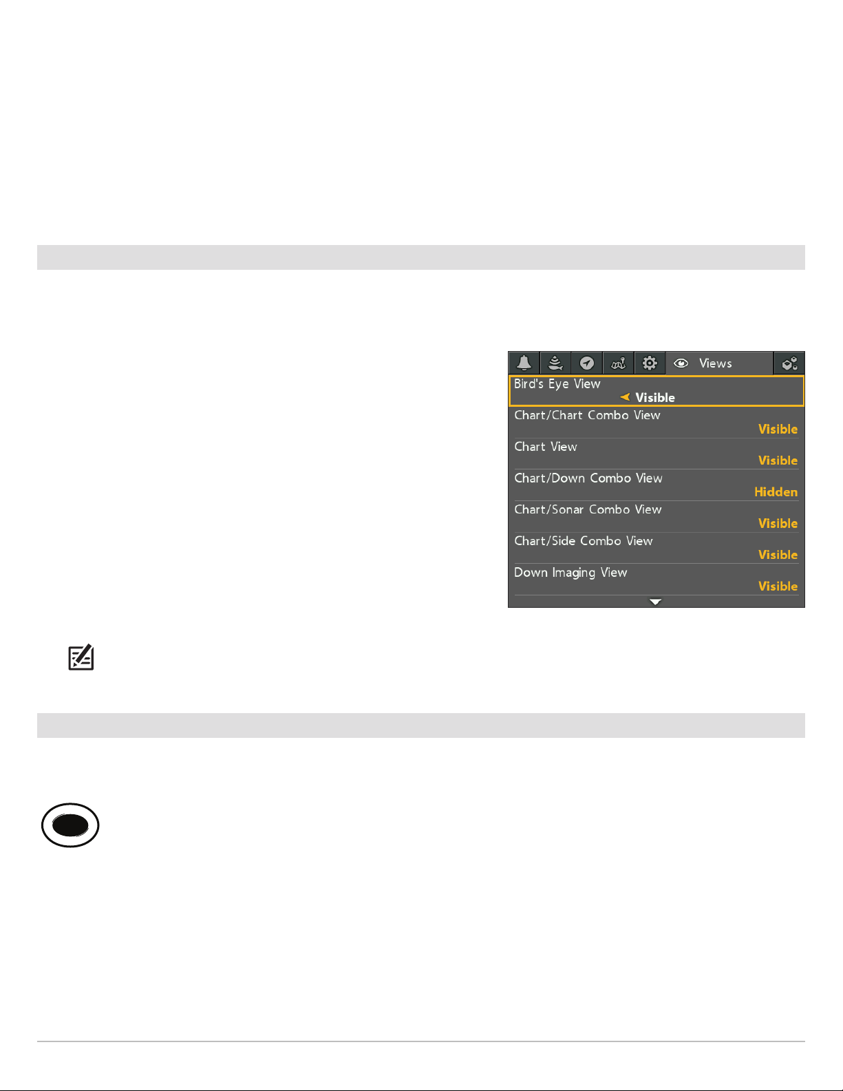
Show your Favorite Views
You can display or hide any view so that each time you press the VIEW key, only your favorite views are displayed on the screen.
Show/Hide a View
1. Main Menu: Press the MENU key twice.
2. Select the Views tab.
3. Select a view.
4. Select Hidden or Visible.
Hide Sonar Views
If you’re using your control head for GPS/Navigation functions only, use these
instructions to hide all sonar views from the view rotation. This setting also
deactivates sonar.
1. Press the POWER key.
2. Select Sonar.
3. Select Off.
NOTE: You can also turn on/off Sonar from the Main Menu > Setup tab > Sonar.
Save a View to a VIEW SHORTCUT key
Main Menu: Views Tab
Another way to display your favorite views quickly is to save them on the VIEW SHORTCUT keys. You can program the VIEW SHORTCUT
keys to display a saved view immediately. You can save one view on each key.
With the view you want to save displayed on-screen, press and hold one of the VIEW SHORTCUT keys for several seconds.
23
Views
Display Digital Readouts
Digital Readout data can be displayed as an overlay, or it can be displayed in data boxes on the views. You can also choose which
digital readouts you want to display. The format and readouts you choose will be applied to all views.
Accessories: The available digital readouts are determined by the installed equipment, so if you connect accessories, additional
readouts will be available.
Format: You can change the digital readout format from the Setup Tab. See Manage your Control Head: Change Digital Readout
Formats for details.
Select the Digital Readout Type
Use the instructions in this section to display digital readouts in boxes or as overlays. You can also choose to hide the digital readouts
completely.
1. Main Menu: Press the MENU key twice. Select the Setup tab.
2. Select Digital Readouts.
3. Select one of the following options:
Digital Readouts are displayed in boxes on the view. See the illustration Digital Readouts with
Boxes
Boxes Selected. You can customize which digital readouts are displayed (see Customize
Digital Readouts).
Overlay
Off
The digital readouts are displayed as an overlay on the view. See the illustrations Digital
Readouts with Overlay Selected. These digital readouts are fixed and cannot be changed.
The digital readouts will be hidden completely. To hide individual digital readouts instead of all,
see Customize Digital Readouts.
Show/Hide Digital Readouts on the Side Imaging View
If you have Digital Readouts set to Boxes on all views, you can hide the digital readout boxes on the Side Imaging View exclusively.
1. Main Menu: Press the MENU key twice. Select the Sonar tab.
2. Select SI Readouts.
3. Select On (show) or Off (hide).
Views
24
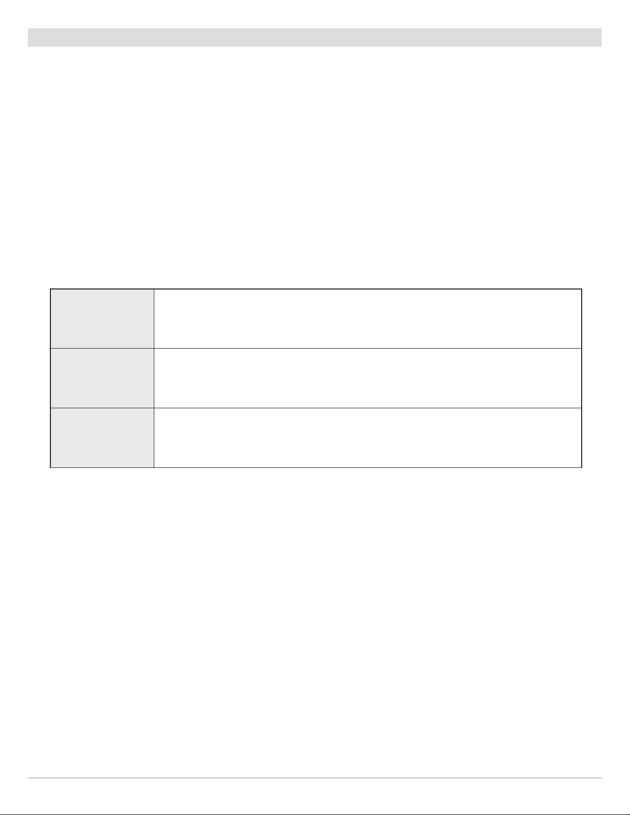
speed
temperature
depth
Digital Readouts with Overlay Selected (Sonar View)
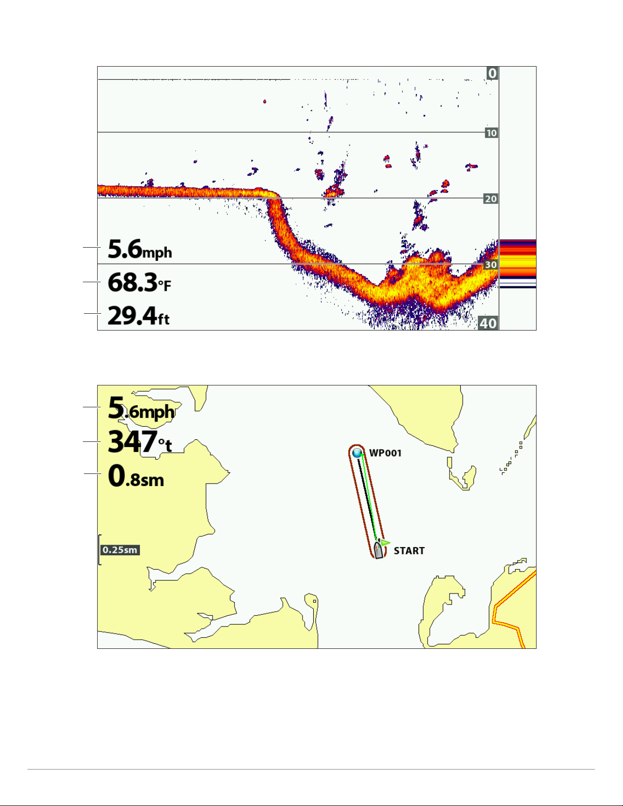
speed
Course Over
Ground (COG)
Distance to Go
(DTG)
Digital Readouts with Overlay Selected (Chart View)
25
Views
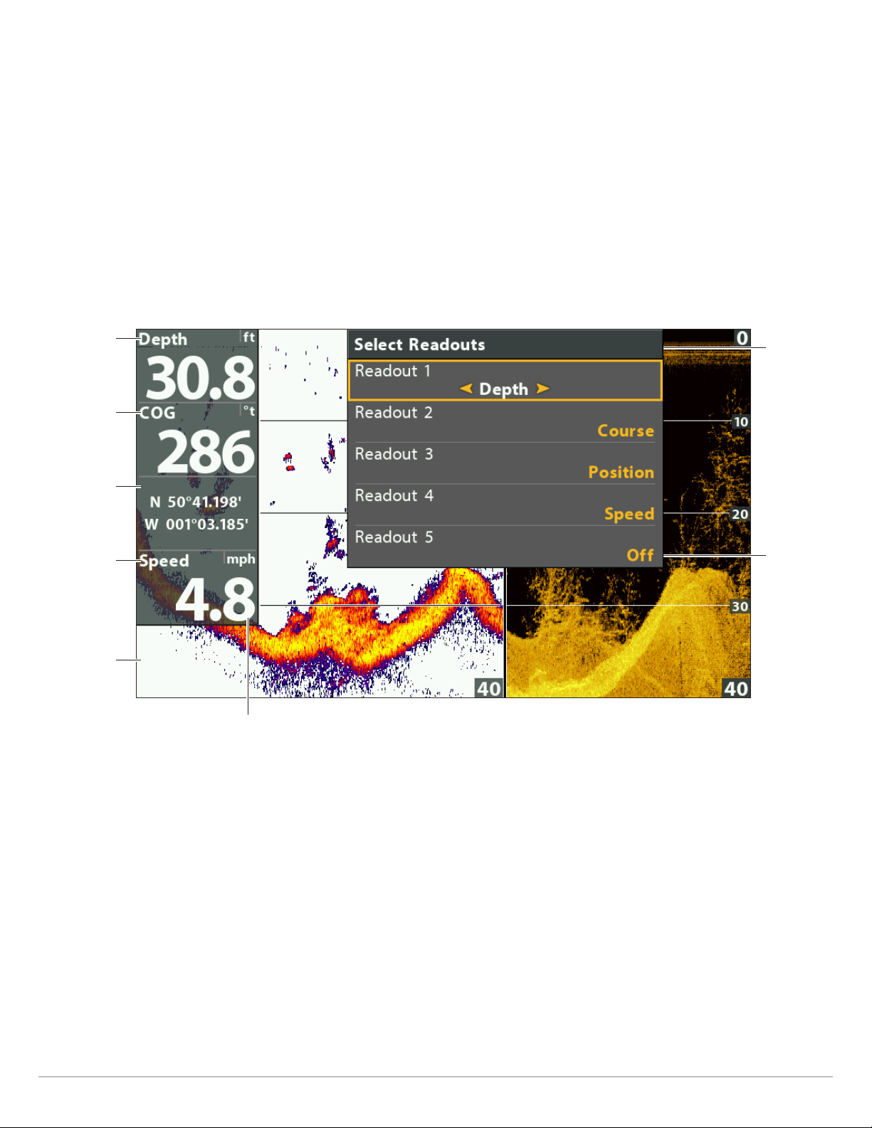
Customize Digital Readouts
If you have Digital Readouts set to Boxes, you can select the data that will be displayed in each box. Use the Select Readouts menu
to set your standard digital readouts. Use the Select Nav Readouts menu to set the digital readouts that will be displayed during
navigation.
1. Main Menu (Advanced User Mode): Press the MENU key twice. Select the Setup tab.
2. Select Select Readouts or Select Nav Readouts. Press the RIGHT Cursor key.
3. Select a readout window (Readout 1, 2, 3, etc.).
4. Select a digital readout.
Hide: To hide a readout window, select Off.
Digital Readouts with Boxes Selected (Down/Sonar Combo View)
readout 1
readout 2
readout 3
readout 4
readout 5
(off = blank)
select
readouts
menu
readout 5
turned off
digits format set
to large tenths
Views
26

Understand Digital Readouts
The following table displays the digital readouts that are available in the Select Readouts menu or the Select Nav Readouts menu.
The available digital readouts are determined by the installed equipment.
Label Name Description
Bearing Bearing
COG
Depth Depth
DTG
ETA
Position (#) GPS
Course Over Ground
(Course)
Distance to Go
(Distance)
Estimated Time
of Arrival
The direction to a destination waypoint measured in degrees from
north.
The direction the boat is traveling measured in degrees from North.
When the COG is equal to Bearing, the boat is said to be on course and
will arrive at the destination in the most efficient manner.
The depth of the water from the transducer or digital depth sensor to
the bottom. This measurement includes the depth offset setting.
If the depth number is flashing, it means the unit is having trouble
locating the bottom. This usually happens if the water is too deep, the
transducer is out of the water, the boat is moving too fast, etc.
The distance between the boat position and the next waypoint on the
route.
The estimated time of arrival to the next waypoint on the route.
The latitude and longitude coordinates of the boat position based on
the GPS receiver installation location.
Navigation
Readout
•
•
•
•
•
Speed Speed
Temp (#) Temperature
Time Time The current time.
Time + Date Time + Date The current time and date.
Timer Timer
Triplog Triplog
TTG Time to Go
VLT Voltage Power supplied to the control head.
Speed is the measurement of the boat’s progress across a given
distance based on the speed measurement provided by the GPS.
The detected water temperature by the transducer’s internal
temperature probe or an accessory temperature sensor.
The digital readout for the timer set in the Alarms tab (see Manageyour
Control Head: Start the Timer).
The elapsed time since the triplog was last reset, the distance traveled
since last reset, and the average speed during timed interval. To reset
the triplog, see Getting Started: Reset the Triplog.
The estimated time required to reach the next waypoint on the route.
TTG is calculated using the SOG (Speed Over Ground) and DTG(Distance
to Go).
•
•
•
XTE Cross Track Error
The straight-line distance of the boat from the intended route. XTE
measures how far the boat is off course.
27
•
Views
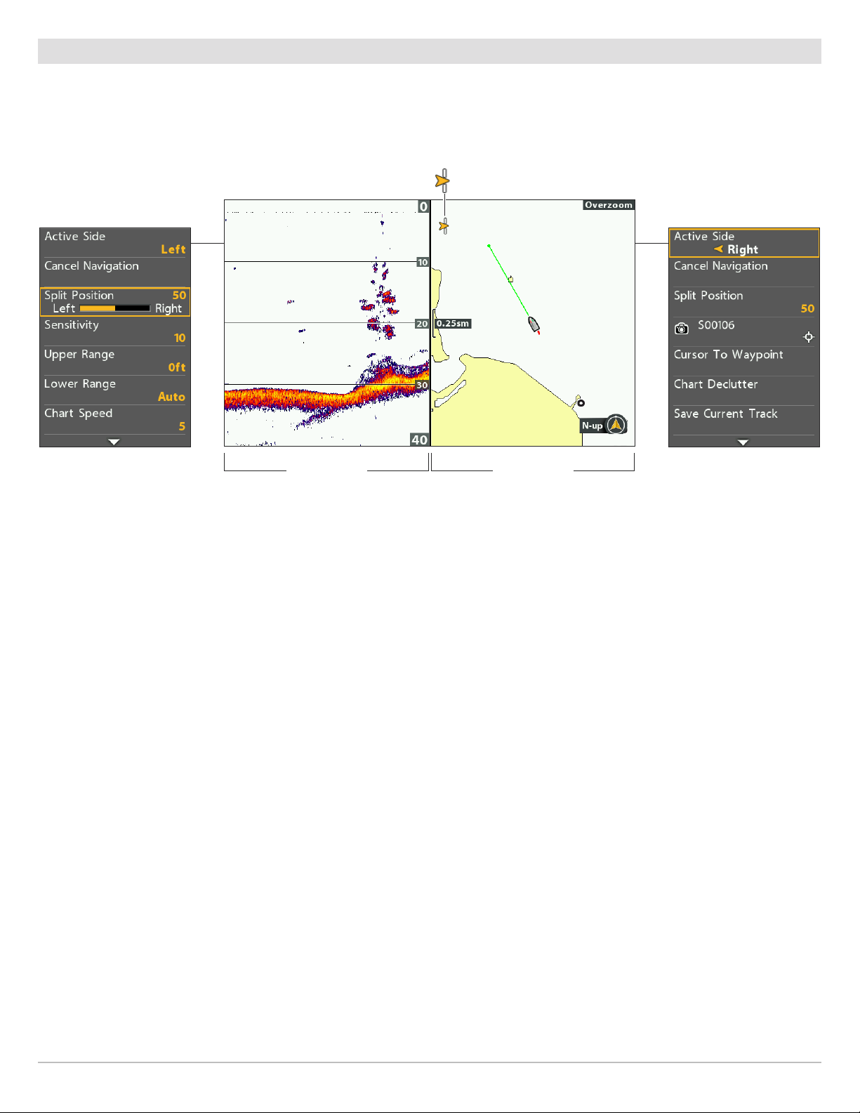
Combo Views
Combo views display two views (or more) on the screen at the same time. You can open the X-Press Menu for the active side of the
view, select menus or actions, and change the size of each window. The available combo views are determined by your Humminbird
model.
Selecting an Active Side of the Chart/Sonar Combo View
points to the active side
of the Combo View
Navigation X-Press MenuSonar X-Press Menu
split position
adjusts window size
split position
adjusts window size
Select an Active Side
To change the settings for either side of the combo view, or to use the cursor on a view, the individual view window must be selected
as the active side.
1. X-Press Menu: With a Combo View displayed on-screen, press the MENU key once.
2. Select Active Side.
3. Select Right or Left.
X-Press Menu: The X-Press Menu updates with the menus available for the active side of the view.
Cursor: Press any arrow on the Cursor Control key to use the cursor on the active side of the view.
Adjust the View Window Size
Split Position allows you to adjust the size of the selected window in a Combo View.
1. X-Press Menu: With a Combo View displayed on-screen, press the MENU key once.
2. Select Split Position.
3. Press the RIGHT or LEFT Cursor keys to adjust the window size.
Views
28
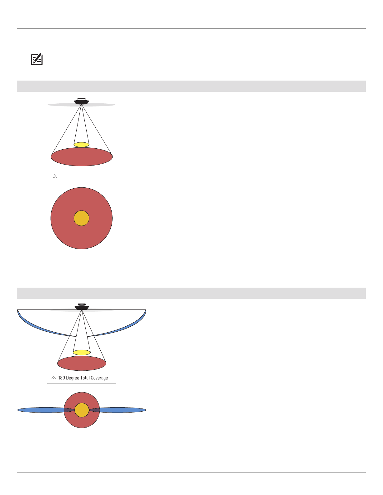
SONAR OVERVIEW (SONAR, DI, SI)
60 Degree Total Coverage
60˚
20˚
200kHz
83kHz
60°
83kHz
20°
200kHz
86°
455kHz
86°
455kHz
A functioning transducer must be attached to the control head to enable sonar functions. To purchase accessory transducers and
Ethernet hardware, visit our Web site at humminbird.com.
NOTE: Depth capability is affected by such factors as boat speed, wave action, bottom hardness, water conditions, and transducer
installation.
DualBeam PLUS Sonar (HELIX SONAR GPS)
The DualBeam PLUS sonar beams provide conical coverage directly below the
boat. DualBeam PLUS sonar returns are displayed on the traditional (2D) Sonar
Views. The beams can be blended together, viewed separately, or compared sideby-side.
The transducer has a narrowly focused 20° center beam, surrounded by a second
beam of 60°, expanding your coverage to an area equal to your depth. In 20 feet
of water, the wider beam covers an area 20 feet wide. The 83/200 kHz transducer
can provide depth coverage up to 1500 feet (500 m).
Side Imaging Sonar (HELIX SI GPS)
The Side Imaging transducer provides a wide yet precise survey of a large area
of water, including detailed bottom topography and fish-attracting structure
orientation.
Typically, the Side Imaging sonar (shown in blue) can search an area that is 480
feet wide (240 to each side), with a typical depth performance of 150 feet when
the Side Imaging Sonar frequency is set for 455 kHz. Selecting 800 kHz (HELIX
10 SI GPS only) produces the sharpest image, but the search area to each side
and the depth capability are limited as compared to the 455 kHz frequency. See
Side Imaging Overview for more information.
The Side Imaging transducer also provides Down Imaging views on the screen,
with the same depth performance of 150 feet. See Down Imaging Overview for
more information.
The DualBeam PLUS sonar beams (shown in magenta and yellow) provide conical
coverage directly below the boat. DualBeam PLUS sonar returns are displayed
on the traditional (2D) Sonar Views, and they will be used in the Side Imaging
View when an area directly under the boat does not have Side Imaging coverage.
The beams can be blended together, viewed separately, or compared side-byside.
29
Sonar Overview

Down Imaging Sonar (HELIX DI GPS)
16°
75°
28°
455kHz
200kHz
455kHz
45°
800kHz
75 Degree Total Coverage
The Down Imaging transducer scans the water with razor-thin, high-definition
beams. The beams are wide (side to side) but very thin front to back.
The Down Imaging beams (shown in green) can be operated at two frequencies:
455 kHz (75°) or 800 kHz (45°). Select 455 kHz for the best overall image quality
and depth. Select 800 kHz for the sharpest image. See Set up Sonar for more
information.
The transducer also uses conical beams to provide data in traditional 2D format
(shown in magenta and yellow). Select 455 kHz for a narrowly focused 16° center
beam, or select 200 kHz for a wider 28° beam (see Set up Sonar and Sonar
Overview).
Sonar Overview
30
 Loading...