

Page 1
Page 2

Thank You!
Thank you for choosing Humminbird®, the #1 name in marine electronics. Humminbird has built
its reputation by designing and manufacturing top-quality, thoroughly reliable marine
equipment. Your Humminbird is designed for trouble-free use in even the harshest marine
environment. In the unlikely event that your Humminbird does require repairs, we offer an
exclusive Service Policy. For complete details, see the separate warranty card included with your
unit. We encourage you to read this manual carefully in order to get the full benefit from all the
features and applications of your Humminbird product.
Contact Humminbird Customer Service at humminbird.com or call 1-800-633-1468.
WARNING! This device should not be used as a navigational aid to prevent collision, grounding, boat
damage, or personal injury. When the boat is moving, water depth may change too quickly to allow
time for you to react. Always operate the boat at very slow speeds if you suspect shallow water or
submerged objects.
WARNING! The electronic chart in your Humminbird unit is an aid to navigation designed to facilitate
the use of authorized government charts, not to replace them. Only official government charts and
notices to mariners contain all of the current information needed for the safety of navigation, and the
captain is responsible for their prudent use.
WARNING! Disassembly and repair of this electronic unit should only be performed by authorized
service personnel. Any modification of the serial number or attempt to repair the original equipment or
accessories by unauthorized individuals will void the warranty.
WARNING! This product contains chemicals known to the State of California to cause cancer and birth
defects or other reproductive harm.
WARNING! Do not travel at high speed with the unit cover installed. Remove the unit cover before
traveling at speeds above 20 mph.
WARNING! Humminbird is not responsible for the loss of data files (waypoints, routes, tracks, groups,
recordings, etc.) that may occur due to direct or indirect damage to the unit’s hardware or software.
It is important to back up your control head’s data files periodically. Data files should also be saved
to your PC before restoring the unit’s defaults or updating the software. See the following sections
of your Humminbird manual: microSD Card Slot and Snapshot and Recording View. Also, contact
Humminbird Customer Service with any questions.
NOTE: Some features discussed in this manual require a separate purchase, and some features are only
available oninternational models. Every effort has been madeto clearly identify thosefeatures. Please read
the manual carefully in order to understand the full capabilities of your model.
NOTE: The illustrations in this manual may not look the same as your product, but your unit will function
in a similar way.
NOTE: To purchase accessories for your control head, visit our Web site at humminbird.com or contact
Humminbird Customer Service at 1-800-633-1468.
NOTE: The procedures and features described in this manual are subject to change without notice. This
manual was written in English and may have been translated to another language. Humminbird is not
responsible for incorrect translations or discrepancies between documents.
Page 3

ATTENTION INTERNATIONAL CUSTOMERS: Products sold in the U.S. are not intended for use in
the international market. Humminbird international units provide international features and are
designed to meet country and regional regulations. Languages, maps, time zones, units of
measurement, and warranty are examples of features that are customized for Humminbird
international units purchased through our authorized international distributors.
Toobtain a list of authorized international distributors, please visit ourWeb site at humminbird.com
or contact Humminbird Customer Service at (334) 687-6613.
ENVIRONMENTAL COMPLIANCE STATEMENT: It is the intention of Johnson Outdoors Marine
Electronics, Inc. to be a responsible corporate citizen, operating in compliance withknown and applicable
environmental regulations, and a good neighbor in the communities where we make or sell our products.
WEEE DIRECTIVE: EU Directive 2002/96/EC “Waste of Electrical and Electronic Equipment Directive
(WEEE)” impacts most distributors, sellers, and manufacturers of consumer electronics in the European
Union. The WEEE Directive requires the producer of consumer electronics to take responsibility for the
management of waste from their products to achieve environmentally responsible disposal during the
product life cycle.
WEEE compliance may not be required in your location for electrical & electronic equipment (EEE), nor
may it be required for EEE designed and intended as fixed or temporary installation in transportation
vehiclessuch as automobiles, aircraft, and boats. In some European Unionmember states,these vehicles
are considered outside of the scope of the Directive, and EEE for those applications can be considered
excluded from the WEEE Directive requirement.
This symbol (WEEE wheelie bin) on product indicates the product must not be disposed of with
other householdrefuse. It mustbe disposed ofand collected for recycling and recovery of waste
EEE. Johnson Outdoors Marine Electronics, Inc. will mark all EEE products in accordance with
the WEEE Directive. It is our goal to comply in the collection, treatment, recovery, and
environmentally sound disposalof those products; however, these requirements do vary within European
Union member states. For more information about where you should dispose of your waste equipment
for recyclingand recovery and/or your European Union member state requirements, please contact your
dealer or distributor from which your product was purchased.
ROHS STATEMENT: Product designed and intended as a fixed installation or part of a system in a vessel
may be considered beyond the scope of Directive 2002/95/EC of the European Parliament and of the
Council of27 January 2003on the restriction of the use of certain hazardous substancesin electrical and
electronic equipment.
ChartSelect™, Down Imaging®, DualBeam PLUS™, Fish ID+™, HELIX™, HumminbirdPC™, Humminbird®, LakeMaster®,
Real Time Sonar™, RTS™, RTS Window™, Structure ID™, SwitchFire®, Total Screen Update™, UniMap™, WhiteLine™,
X-Press™ Menu, and Xtreme Depth Series™ are trademarked by or registered trademarks of Johnson Outdoors Marine
Electronics, Inc.
Adobe, Acrobat, Adobe PDF, and Reader are either registered trademarks or trademarks of Adobe Systems Incorporated in
the United States and/or other countries.
Baekmuk Batang, Baekmuk Dotum, Baekmuk Gulim, and Baekmuk Headline are registered trademarks owned by Kim
Jeong-Hwan.
microSD is a trademark or registered trademark of SD-3C, LLC in the United States, other countries or both.
Navionics® Gold, HotMaps™, and HotMaps™ Premium, Navionics® Classic Charts, and Platinum™ Cartography are
trademarked by or registered trademarks of Navionics S.p.A.
© 2015 Johnson Outdoors Marine Electronics, Inc. All rights reserved.
532306-3EN_B
Page 4

Table of Contents
HELIX Series Overview 1
How Sonar Works 1
How GPS and Cartography Work 6
Power On 7
What’s on the Control Head 8
Key Functions 9
microSD Card Slot 13
Add Maps to your Control Head .............................................................................................................. 14
Import Navigation Data ............................................................................................................................ 15
Export Navigation Data.............................................................................................................................. 15
Update Software........................................................................................................................................ 17
What’s on the Sonar Display 18
What’s on the Down Imaging Display 24
Views 27
Select a View ............................................................................................................................................ 27
Display your Favorite Views ...................................................................................................................... 27
Change Digital Readouts .......................................................................................................................... 28
Combo Views ............................................................................................................................................ 30
Chart View Orientation 54
Viewing Cartography 55
Introduction to Navigation 57
Waypoints, Routes, and Tracks ................................................................................................................ 57
Open the Waypoint Management Dialog Box.......................................................................................... 59
What’s on the Waypoint Management Dialog Box ................................................................................ 60
Save, Edit, or Delete a Waypoint .............................................................................................................. 62
Navigate to a Waypoint or Position .......................................................................................................... 62
Add a Waypoint Target or Trolling Grid .................................................................................................... 63
Routes ........................................................................................................................................................ 64
Tracks.......................................................................................................................................................... 66
Edit your Waypoints, Routes, Tracks, and Groups.................................................................................... 66
Man Overboard (MOB) Navigation .......................................................................................................... 68
i
Page 5

Table of Contents
The Menu System 70
Start-Up Options Menu 71
X-Press Menu 75
Main Menu 76
Quick Tips for the Main Menu .................................................................................................................. 77
Note for all Menu Settings........................................................................................................................ 77
User Mode (Normal or Advanced)............................................................................................................ 78
Sonar X-Press Menu 80
Flasher X-Press Menu 85
Snapshot and Recording X-Press Menu 88
Down Imaging X-Press Menu 92
Navigation X-Press Menu 96
Alarms Menu Tab 103
Sonar Menu Tab 108
Navigation Menu Tab 119
Chart Menu Tab 125
Setup Menu Tab 132
Views Menu Tab 140
Maintenance 141
Troubleshooting 142
HELIX Control Head Measurements 145
Specifications 149
Contact Humminbird 157
ii
Page 6

Page 7
HELIX Series Overview
The HELIX Series is available in several different configurations. See the following list of products,
all of which are covered by this manual, to find your HELIX Series model:
• HELIX SONAR GPS: Wide screen Fishfinder with DualBeam PLUS (2D) sonar,
chartplotting, and an internal GPS receiver.
• HELIX DI GPS: Wide screen Fishfinder with Down Imaging sonar, traditional 2D sonar,
chartplotting, and an internal GPS receiver.
• HELIX XD GPS: Wide screen Fishfinder with Xtreme Depth sonar, chartplotting, and an
internal GPS receiver.
• HELIX GPS: Wide screen chartplotter with an internal GPS receiver. This model has exclusive
views for chartplotting. Please note that the chartplotter does not include the sonar features
described in this manual (fishfinder, sonar, recording, depth, transducer, etc.).
NOTE: Some features discussed in this manual require a separate purchase, and some features are only
available on international models. Every effort has been made to clearly identify those features. Please read
the manual carefully in order to understand the full capabilities of your model.
How Sonar Works
Sonar technology is based on sound waves. The HELIX Series Fishfinder uses sonar to locate
and define structure, bottom contour and composition, as well as depth directly below the
transducer.
Your HELIX Series Fishfinder sends a sound wave signal and determines distance by measuring
the time between the transmission of the sound wave and when the sound wave is reflected
off of an object; it then uses the reflected signal to interpret location, size, and composition of
an object.
Sonar is very fast. A sound wave can travel from the surface to a
depth of 240 ft (70 m) and back again in less than 1/4 of a second.
It is unlikely that your boat can "outrun" this sonar signal.
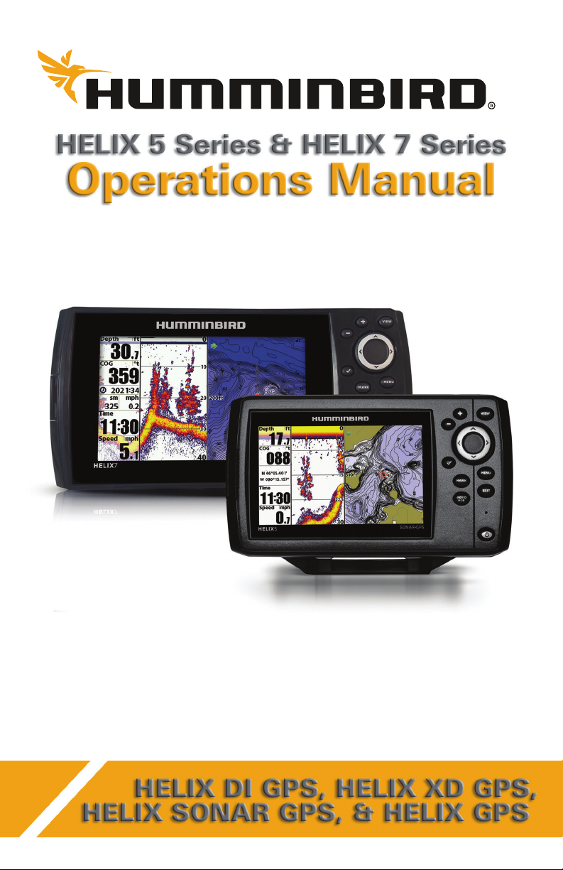
SONAR is an acronym for SOund and NAvigation Ranging. Sonar
utilizes precision sound pulses or "pings" which are emitted into
the water in a teardrop-shaped beam.
The sound pulses “echo” back from objects in the water such as
the bottom, fish, and other submerged objects. The returned
echoes are displayed on the LCD screen. Each time a new echo is
received, the old echoes are moved across the LCD, creating a
scrolling effect.
1
Overview and How Sonar Works
Page 8
When all the echoes are viewed side by side, an easy to interpret
“graph” of the bottom, fish, and structure appears.
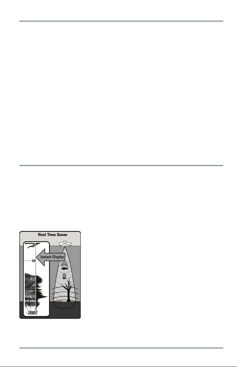
The sound pulses are transmitted at various frequencies depending
on the application. Very high frequencies (455 kHz) are used for
greatest definition but the operating depth is limited. High
frequencies (200 kHz) are commonly used on consumer sonar and
provide a good balance between depth performance and
resolution. Low frequencies (83 kHz) are typically used to achieve
greater depth capability.
How Sonar Works
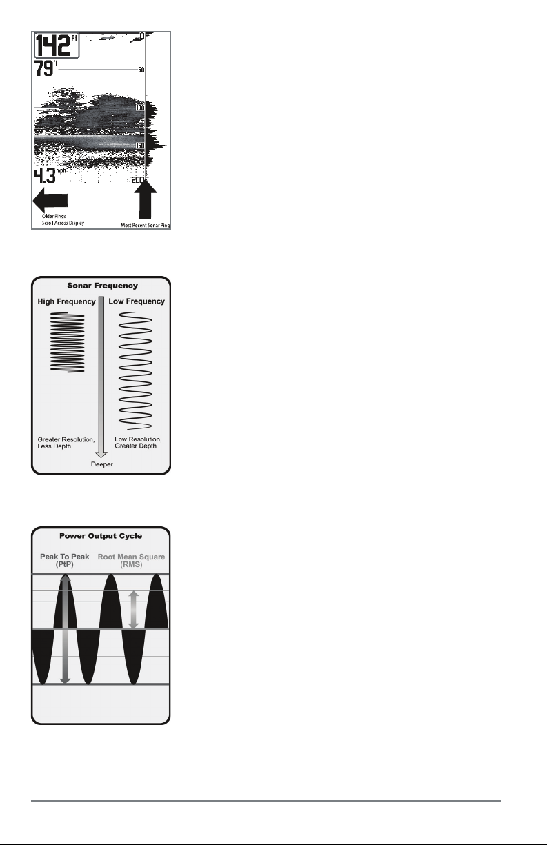
The power output is the amount of energy generated by the sonar
transmitter. It is commonly measured using two methods:
• Root Mean Square (RMS) measures power output over the
entire transmit cycle.
• Peak to Peak measures power output at the highest points.
The benefits of increased power output are the ability to detect
smaller targets at greater distances, ability to overcome noise,
better high speed performance, and enhanced depth capability.
2
Page 9
20˚
60˚
200kHz
83kHz
60 Degree Total Coverage
Bottom Coverage = 1 x Depth
28°
16°
455kHz
200kHz
800kHz
45°
455kHz
75 Degree Total Coverage
75°
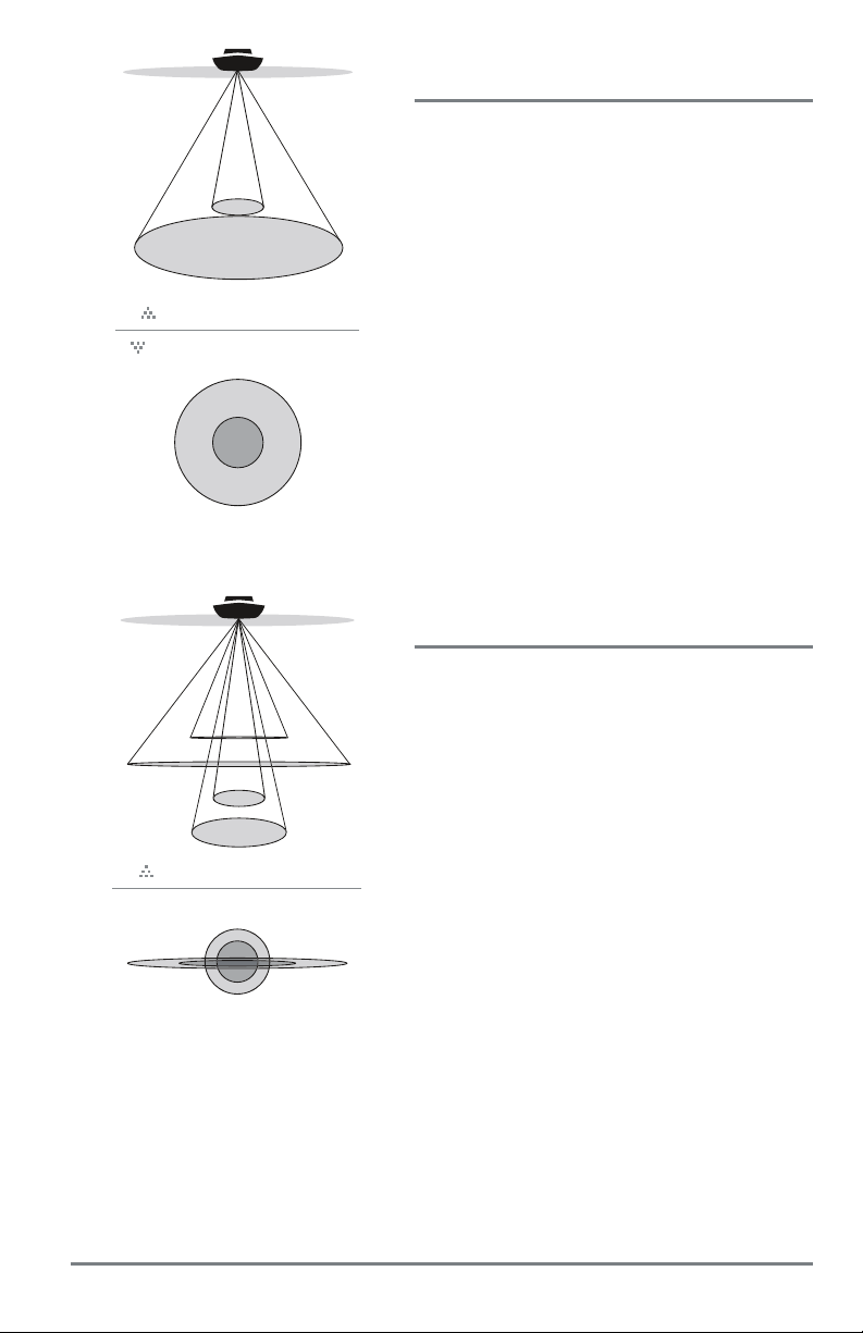
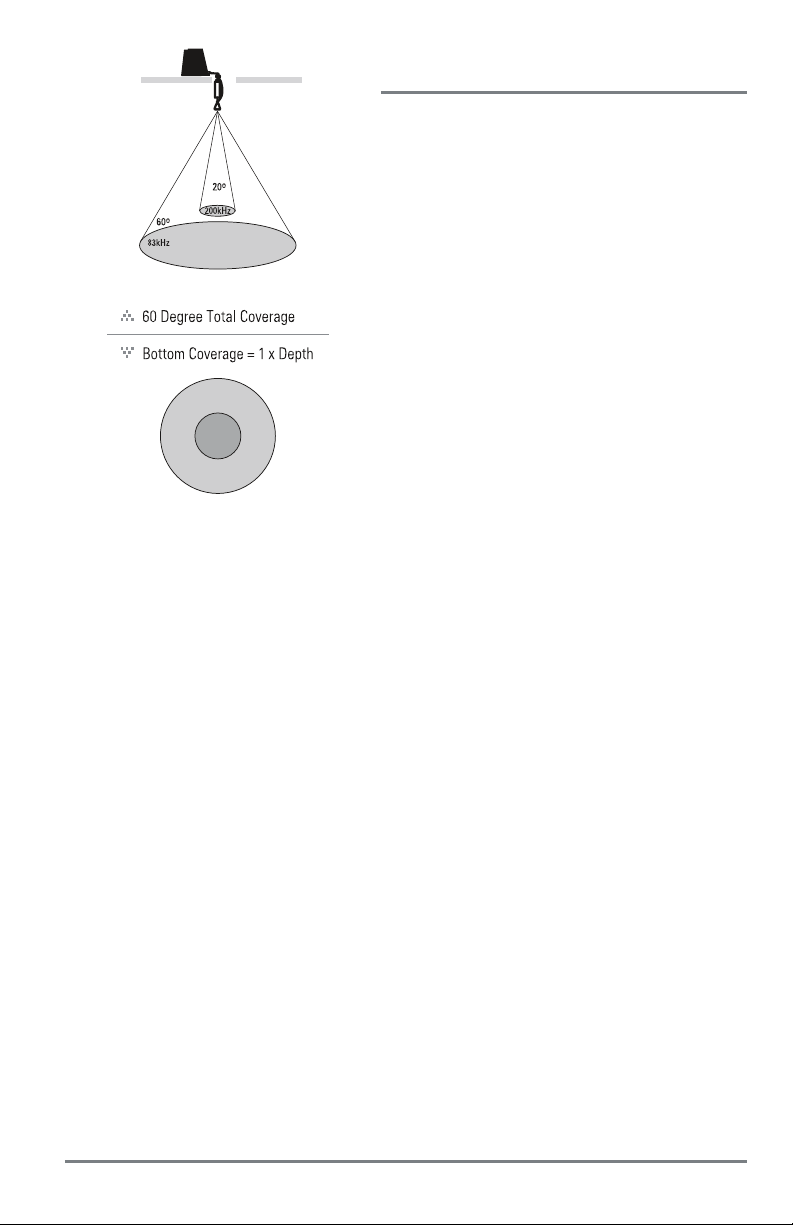
DualBeam PLUS Sonar
(HELIX SONAR GPS)
The HELIX SONAR GPS Fishfinder uses a
200/83 kHz DualBeam PLUS sonar system with a
wide (60°) area of coverage. DualBeam PLUS sonar
has a narrowly focused 20° center beam, surrounded
by a second beam of 60°, expanding your coverage to
an area equal to your depth. In 20 feet of w ater, the
wider beam cover s an area 20 feet wide. DualBeam
PLUS sonar returns can be blended together, viewed
separately, or compared side-by-side.
DualBeam PLUS is ideal for a wide range of
conditions - from shallow to very deep water in both
fresh and salt water.
Depth capability is affected by such factors as boat
speed, wave action, bottom hardness, water
conditions, and transducer installation.
Down Imaging Sonar
(HELIX DI GPS)
The HELIX DI GPS Fishfinder uses Down Imaging
technology. The Down Imaging transducer scans the
water with razor-thin, high-definition beams. The
beams are wide (side to side) but very thin front to
back.
The Down Imaging beams can be operated at two
frequencies: 455 kHz (75°) or 800 kHz (45°). Select
455 kHz for the best ov erall image quality and depth.
Select 800 kHz for the sharpest image. See Sonar
Menu T ab: Imaging Frequency for more information.
The transduceralso uses conical beams to provide data
in traditional 2D format (see What’s on the Sonar
Display). Select 455 kHz for a narro wly focused 16°
center beam, or select 200 kHz for a wider 28° beam
(see Sonar Menu Tab: Beam Select).
Depth capability is affected by such factors as boat
speed, wave action, bottom hardness, water
conditions, and transducer installation.
3
How Sonar Works
Page 10
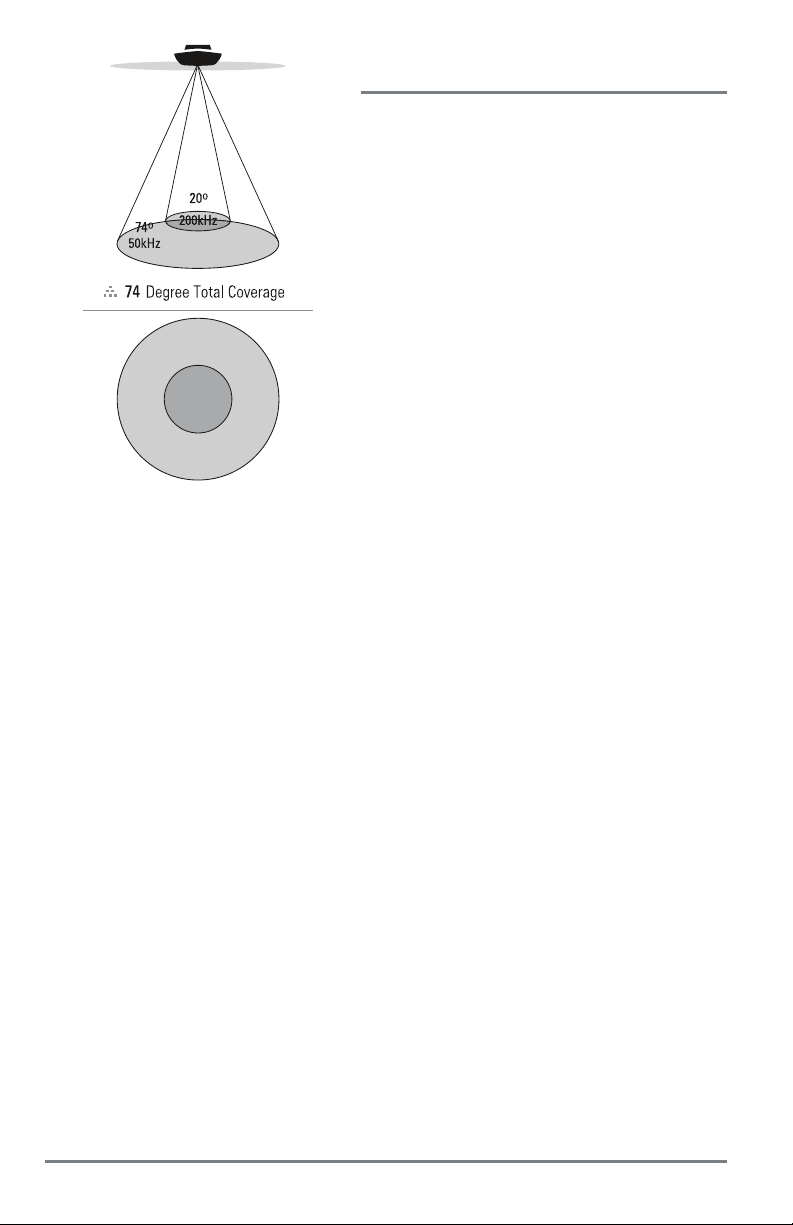
Xtreme Depth Sonar
(HELIX XD GPS)
The HELIX XD GPS Fishfinder uses the XD
transducer to provide extreme depth coverage with
DualBeam PLUS technology.
The Xtreme Depth sonar beams can be operated at
two frequencies: 50 kHz (74°) and 200 kHz (20°). The
wide, 50 kHz beam transmits at a low frequency to
provide greater depth coverage, up to 2500 ft (762 m).
The narrow, 200 kHz center beam transmits at a high
frequency to provide maximum detail at shallower
depths.
The DualBeam PLUS technology allows you to view
the sonar returns blended together, separately, or
side-by-side (see Sonar Menu Tab: Beam Select and
Views for more information).
Depth capability is affected by such factors as boat
speed, wave action, bottom hardness, water
conditions, and transducer installation.
How Sonar Works
4
Page 11
Dual Beam Ice Transducer
(with optional-purchase XI 9 20 Ice Transducer)
The XI 9 20 Ice Transducer provides selectable
dual-frequency sonar with a wide area of coverage.
Selectable dual-frequency gives you the option of
two beams, and both beams will cover the bottom
and provide high definition. The 20° center beam
provides the highest definition, while the 60° beam
provides wider coverage. Depth capability is
affected by such factors as bottom hardness and
water conditions. Whether fishing in shallow or
very deep water, selectable dual-frequency is ideal
for a variety of conditions.
NOTE: Contact Humminbird Customer Service to
determine which accessory transducers are compatible
with your control head, or visit our Web site at
humminbird.com.
5
How Sonar Works
Page 12

How GPS and Cartography Work
Your control head also supports GPS (Global Positioning System) and chartplotting. It uses GPS
and sonar to determine your position, display it on a grid, and provide detailed underwater
information.
GPS uses a constellation of satellites that continually send radio
signals to the earth. The GPS receiver receives signals from satellites
that are visible to it. Based on time differences between each
received signal, the GPS receiver determines its distance to seach
satellite. With distances known, the GPS receiver mathematically
triangulates its own position. With 5 updates per second, the GPS
receiver then calculates its velocity and bearing.
GPS was originally intended for military use; however, civilians may also take advantage of its
highly accurate position capabilities, typically within +/- 4.5 meters, depending on conditions. This
means that 95% of the time, the GPS receiver will read a location within 4.5 meters of your actual
position. Your GPS Receiver also uses information from WAAS (the Wide Area Augmentation
System), EGNOS (thes European Geostationary Navigation Overlay Service), and MSAS (the
MTSAT Satellite Augmentation System) satellites if they are available in your area.
The following GPS functionality is currently supported by the control head:
• View current position
• View current track (breadcrumb trail)
• View precision speed and heading from your GPS receiver
• Save tracks, waypoints, and routes
• Travel a route and navigate from one waypoint to the next
See Views: Chart View and microSD Card Slot: Add Maps to your Control Head for more
information.
How GPS and Cartography Work
6
Page 13

Power On
Follow the instructions below to power on your Humminbird control head.
HELIX Series Title Screen
1. Press the POWER/LIGHT key.
2. When the Title screen is displayed, press the MENU key to access the Start-Up Options
Menu.
3. Select Normal, and press the RIGHT Cursor key.
• If you wait too long to select a Start-Up Option, the system will default to whichever
menu is already highlighted.
• HELIX SONAR GPS, HELIX DI GPS, HELIX XD GPS: If a functioning transducer is
connected, Normal operation will be selected automatically, and your control head
can be used on the water.
• You can also select Simulator to learn how to use your control head and save
settings in advance for later use. See Start-Up Options Menu for more information.
4. Quick Setup: If this is the first time the unit has been powered on (after installation or
after restoring defaults), the Quick Setup dialog box will display on the screen. Use the
4-WAY Cursor Control key to change the settings. Press the EXIT key to close the dialog
box.
NOTE: The Quick Setup settings can be changed at any time. See each menu option in The Menu System
for details.
7
Power On
Page 14
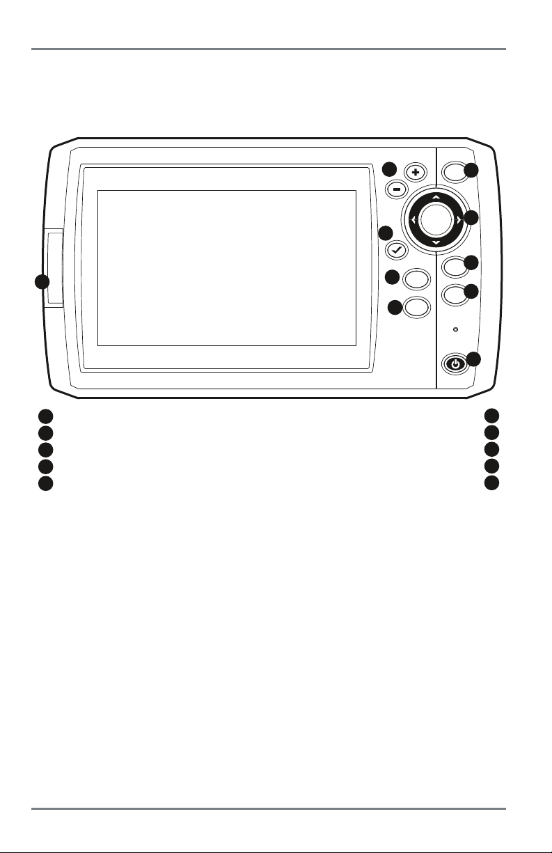
What’s on the Control Head
Your HELIX Series user interface is easy to use. A combination of keys, different views, and
situation-specific, customizable menus allows you to control what you see on the color display.
Refer to the following illustration and see Key Functions, Views, and The Menu System for more
information.
2
5
7
1
1
microSD Card Slot
2
ZOOM (+/-) Keys
3
VIEW Key
4
4-WAY Cursor Control Key (LEFT, RIGHT, UP, or DOWN) GOTO/MOB Key
5
CHECK/INFO Key POWER/LIGHT Key
MARK
GOTO
9
MOB
3
VIEW
4
6
MENU
8
EXIT
10
MENU Key
MARK Key
EXIT Key
6
7
8
9
10
What’s on the Control Head
8
Page 15
Key Functions
Your control head consists of a set of easy-to-use keys that work with various on-screen views
and menus.
POWER/LIGHT Key
The POWER/LIGHT key is used to power the control head on and off. You can also
use the POWER/LIGHT key to adjust the backlight and contrast of the display.
Power On: Press the POWER/LIGHT key to power on the unit. When the Title screen is displayed,
press the MENU key to access the Start-Up Options Menu.
Power Off: Press and hold the POWER/LIGHT key for 3 seconds. A message will appear to indicate
how many seconds there are until shutdown occurs. To ensure that shutdown occurs properly and
any menu settings will be saved, your control head should always be turned off using the
POWER/LIGHT key.
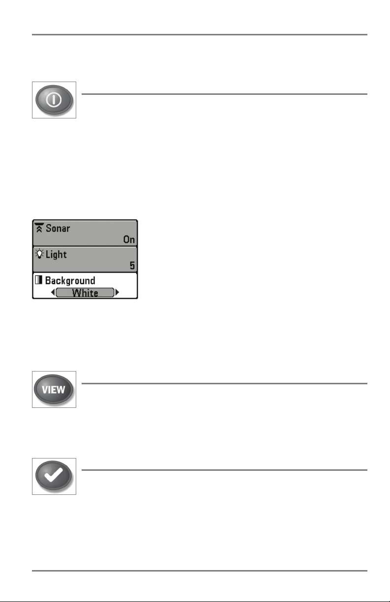
Adjust the Backlight or the Display Background Color: Press
the POWER/LIGHT key to access the Light and Background
submenu. Use the 4-WAY Cursor Control key to select Light or
Background, and then use the LEFT or RIGHT Cursor key to
change the settings. Press EXIT to exit the Light and Background
submenu.
Turn Sonar On or Off: From the Light and Background submenu, use the 4-WAY Cursor Control
key to select Sonar. Use the LEFT or RIGHT Cursor key to change the setting. See Setup Menu
T ab: Sonar for more information.
VIEW Key
The VIEW key is used to cycle through all available views. Press the VIEW key to
advance to the next view. Repeatedly pressing VIEW cycles through all views
available (see Views or Views Menu Tab).
NOTE: Press the EXIT key to cycle through the views in reverse order.
CHECK/INFO Key
Press the CHECK/INFO key while in Bird's Eye, Chart, or Combo View to display
information about objects that are near an active cursor. If the cursor is not active,
the Chart Info submenu will be displayed. See Views: Viewing Cartography for
more information.
9
Key Functions
Page 16
MENU Key
The MENU key is used to access the menu system. See The Menu System for more
information.
• Start-Up Options Menu: Press the MENU key during the power up sequence to view the
Start-Up Options menu.
• X-Press Menu: Press the MENU key once in any view to access the X-Press Menu, which
provides frequently-used menu settings that correspond with the current view or
navigation mode.
• Main Menu: Press the MENU key twice in any view to access the Main Menu, which is
organized under tabbed headings to help you find a specific menu item quickly.
4-WAY Cursor Control Key
(LEFT, RIGHT, UP, or DOWN Cursor keys)
The 4-WAY Cursor Control key has multiple functions, depending on the view,
menu, or situation.
• Menu Selection: Press the DOWN or UP Cursor keys to highlight a menu option, then
press the RIGHT or LEFT Cursor keys to change a menu setting.
NOTE: Menu settings are implemented and saved immediately - no further action is required.
• Freeze Frame: In Sonar View and Down Imaging View, press any arrow on the 4-WAY
Cursor Control key to freeze the display and move the active cursor to a location on the
screen. A cursor dialog box will display to show the depth of the location you choose.
• Active Cursor: Press any arrow on the 4-WAY Cursor Control key, and the active cursor
will appear on the screen.
• Chart View: Press any arrow on the 4-WAY Cursor Control key to pan the chart and
highlight decluttered waypoint icons.
NOTE: In Freeze Frame or Active Cursor mode, you can also make the cursor move diagonally by
pressing in between two of the arrows on the 4-WAY Cursor Control ke y.
• Bird’s Eye View: The 4-WAY Cursor Control key controls the motion of the eye point.
• Snapshot and Recording View: Press the UP or DOWN Cursor keys to highlight a
recording icon, and then press the RIGHT Cursor key to start recording playback. Press the
RIGHT or LEFT Cursor keys to control the speed of playback.
• Circular Flasher View (Ice Fishing Mode: On): Press the UP or DOWN Cursor keys to
move the Depth Cursor. Press the RIGHT or LEFT Cursor keys to adjust the Zoom Range
(see Views: Circular Flasher View).
Key Functions
10
Page 17
MARK Key
Press the MARK key while in any view to mark the position of a waypoint.
• Active Cursor: The waypoint will be marked at the cursor location.
• Without Active Cursor: The waypoint will be marked at the boat location.
• If Screen Snapshot is active, a waypoint will be created, and a screen snapshot will also
be saved to the optional-purchase microSD Card (see Views: Snapshot and Recording
View). Navigation is not affected by the Screen Snapshot feature.
NOTE: If Screen Snapshot is enabled but there is not a GPS receiver connected, pressing the MARK
key will capture the screen image and display an error saying that a GPS position fix is required to
create a waypoint.
NOTE: You must have an optional-purchase microSD Card installed for the screen snapshot featur e
to work.
GOTO/Man Overboard Key
The GOTO/MOB key has multiple functions, depending on the situation:
• Active Cursor: Press the GOTO key while in any view to create a waypoint and start
navigation towards that waypoint.
• Without Active Cursor: Press the GOTO key to display the saved waypoints list, and then
highlight a waypoint. Press the RIGHT Cursor key to begin navigation.
• Man Overboard: Press and hold the GOTO key for more than 1.5 seconds to activate the
Man Overboard (MOB) function. Once MOB is activated, any current navigation will be
cancelled and the current route will be discarded without notification (see Introduction
to Navigation: Man Overboard (MOB) Navigation).
11
Key Functions
Page 18
ZOOM (+/–) Key
The Zoom (+/–) key has multiple functions, depending on the situation:
• In any of the Navigation Views or the Sonar Zoom View, press the +/– Zoom key to
change the scale of the view to appear closer or farther away . See Views and Introduction
to Navigation for more information.
• In the Circular Flasher View (Ice Fishing Mode: On), press the +Zoom key to display a
2x magnified view of the selected area on the Flasher dial. See Views: Circular Flasher
View for more information.
• Down Imaging View: Use the 4-WAY Cursor Control key to move the active cursor to a
position on the screen. Press the + ZOOM key to magnify your selection. Press the – Zoom
key to decrease the scale.
NOTE: The cursor must be active for the zoom feature to work in the Down Imaging View.
EXIT Key
The EXIT key has multiple functions, depending on the situation:
• If an alarm is sounding, press the EXIT key to cancel the alarm.
• If a menu tab is selected, press the EXIT key to exit the menu mode and return to the
view.
• If a menu is active, press the EXIT key to return to the previous level in the menu system.
• From any view, press the EXIT key to cycle through the available views in reverse order.
• If Freeze Frame is active, press the EXIT key to return to a scrolling display.
• If the Cursor is active, press the EXIT key to remove the cursor from the display.
• If Down Imaging Zoom is active, press the EXIT key to remove the magnification box
from the display and remove the cursor.
Key Functions
12
Page 19
microSD Card Slot
The microSD card slot on your control head can be used with a microSD card (separate purchase
required) to add detailed charts to your control head, import/export navigation data, and save
sonar recordings (see Snapshot and Recording View for details).
NOTE: The microSD Card requires a separate purchase. For more information, visit our Web site at
humminbird.com or contact Humminbird Customer Service at 1-800-633-1468.
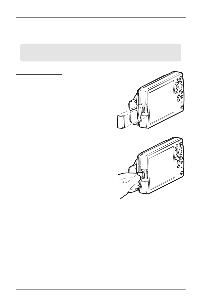
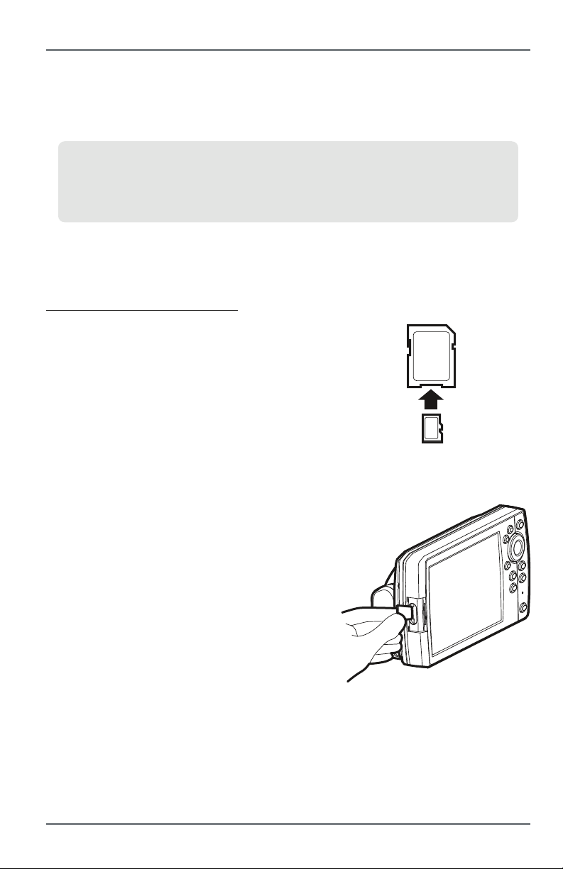
To insert a microSD Card:
1. Remove the microSD card slot cover.
2. Position the microSD card so that the label faces
the front of the control head and the card notches
face down.
3. Insert the card into the slot until it clicks into
place.
4. Replace the slot cover so it is secure.
5. To Remove: Press the card into the slot and then
release it. The card will eject. Pull the card
carefully from the slot.
NOTE: Do not leave the microSD card slot cover open. The
slot cover should always be closed to prevent water
damage to the unit.
13
Inserting a microSD Card into the Card Slot
microSD Card Slot
Page 20

Add Maps to your Control Head
Your control head includes a built-in UniMap with a more detailed map of North America
(Domestic models) or a detailed map of Europe and Southeast Asia, including Australia and New
Zealand (International models).
You can also purchase microSD cards with additional chart information for a particular location.
NOTE: The microSD card requires a separate purchase. Your control head supports
Humminbird LakeMaster, Navionics Gold, HotMaps, and HotMaps Premium on microSD card media.
Your control head does NOT support Navionics Classic Charts or Platinum Cartography.
• Auto Select: When you install the microSD card in your control head, it will retrieve the
chart and display it automatically.
• Chart Select: You can also choose which chart to display with the Chart Select menu
option in the Chart Menu Tab (see Chart Menu Tab: Chart Select).
• Chart Layers: You can customize your Navigation Views by selecting which chart layers
to display or hide (see Chart Menu Tab: Chart Detail Level).
• Map Borders: Use the 4-WAY Cursor Control key to move the active cursor within a map
border, and press the +ZOOM key to view the different map (see Chart Menu Tab: Map
Borders).
• Menu Options: The Chart Menu Tab will change to display menu options that correspond
with the active chart (see Chart Menu Tab).
microSD Card Slot
14
Page 21

Import Navigation Data
Review the following information before importing navigation data (waypoints, routes, tracks,
or groups) into your Humminbird unit.
WARNING! DO NOT import navigation data from unknown sources into your Humminbird unit
without first converting the data to the correct format using HumminbirdPC. Importing corrupted data
can cause the unit to malfunction, which can result in lost navigation data.
• Import Humminbird Navigation Data: Insert a loaded microSD card into the control head
card slot, and follow the on-screen prompts to import the waypoints, routes, tracks, and
groups.
NOTE: For more information and instructions, see the FAQ (Frequently Asked Questions) section of
our Web site at humminbird.com or call Humminbird Customer Service at 1-800-633-1468.
Export Navigation Data
The Humminbird Waypoint Management dialog box allows you to export all of your navigation
items to an installed, unlocked microSD card. You can also export selected items.
For more information, see Introduction to Navigation: What’s on the Waypoint
Management Dialog Box. Also, see your Humminbird Waypoint Management Guide
for complete details.
It is important to back up your control head’s data files (waypoints, routes, tracks,
groups, recordings, etc.) periodically. You can also save, view, and organize your
navigation data on your PC using HumminbirdPC. See your Humminbird online account
fordetailsathumminbird.com.
15
microSD Card Slot
Page 22

To export all navigation data:
Use the following instructions to export all of the control head’s waypoints, routes, tracks, and
groups to an installed, unlocked microSD card.
1. Insert an unlocked microSD card into the card slot.
2. Open the Waypoint Management Dialog Box: Press the MENU key twice. Press the
RIGHT Cursor key until the Navigation tab is selected. Select Waypoints, Routes, Tracks.
Press the RIGHT Cursor key.
3. Select Options > Select All and... > Export.
4. Follow the on-screen instructions to confirm or cancel the export.
To export selected navigation items:
Use the following instructions to select and export specific waypoints, routes, tracks, and groups
to an installed, unlocked microSD card.
1. Insert an unlocked microSD card into the card slot.
2. Open the Waypoint Management Dialog Box: Press the MENU key twice. Press the
RIGHT Cursor key until the Navigation tab is selected. Select Waypoints, Routes, Tracks.
Press the RIGHT Cursor key.
3. From a selected group directory in the Waypoint Management dialog box, select
Options > Select Multiple and... > Export.
4. Select Items: Press the UP or DOWN Cursor keys to scroll through the waypoints, routes,
tracks, and groups. Press the RIGHT Cursor key to select an item. Repeat as needed.
5. Confirm Export: When you are finished selecting items, press the EXIT key to select
Export Selected. Press the RIGHT Cursor key and follow the on-screen instructions to
confirm or cancel the export.
NOTE: If a microSD card is not installed, an error message will be displayed. Insert the card and try
again.
NOTE: The microSD card and adapter require separate purchases. Visit our Web site at
humminbird.com or contact Humminbird Customer Service at 1-800-633-1468.
microSD Card Slot
16
16
Page 23
Update Software
Set up an online account at humminbird.com so that you will receive the latest Humminbird
news and software updates for your Humminbird model. You can also download HumminbirdPC
from your account, which allows you to manage your waypoints, routes, and tracks on your
personal computer.
NOTE: It is important to back up your control head’s data files (waypoints, routes, tracks, groups,
recordings, etc.) periodically. Data files should also be saved to your PC before restoring the unit’s
defaults or updating the software. See Export Navigation Data and Snapshot and Recording Vie w
for more information. Also, contact Humminbird Customer Service with any questions.
Required Equipment: Personal computer with Internet access, a formatted microSD card, and a
microSD card adapter.
To update the control head software:
1. Install a formatted microSD card into the
adapter, and insert it into the slot on your PC.
2. Register your Control Head: Log on to
humminbird.com. Click My Humminbird. Set up
a new account.
3. Download: Select the My Equipment page. The
available software updates are listed as
Downloads under each registered product.
• Under Downloads, click the file name.
• Read the instructions in the dialog box and
select Download.
• Follow the on-screen prompts to save the
software file to the microSD card.
4. Install the microSD card with the updated
software file into the control head card slot.
5. Power on: The control head will recognize the
new software and run through a series of
prompts to confirm software installation.
Inserting a microSD Card into the Adapter
Inserting a microSD Card into the Card Slot
17
microSD Card Slot
Page 24
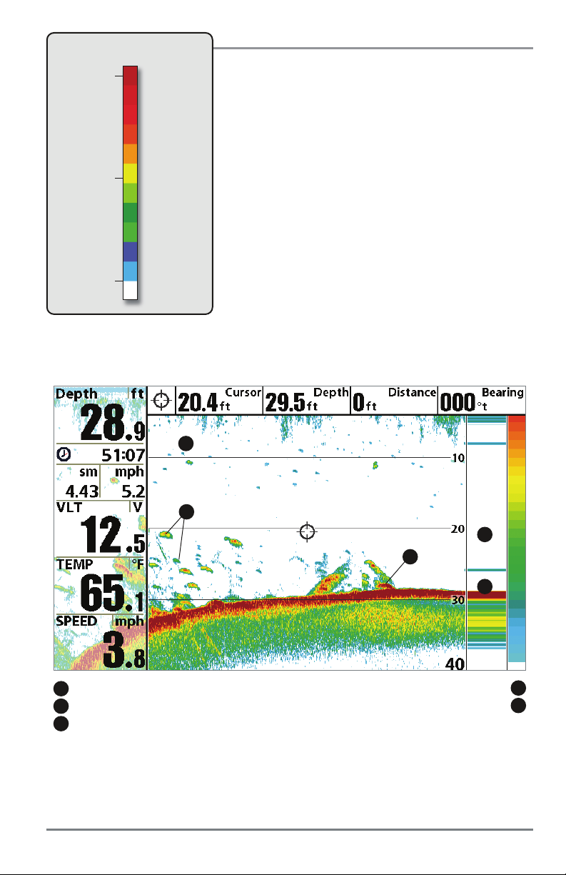
What’s on the Sonar Display
The Fishfinder can display a variety of useful information about the area under and adjacent to
1
2
Tri p log
3
5
6
7
1
2
4
12
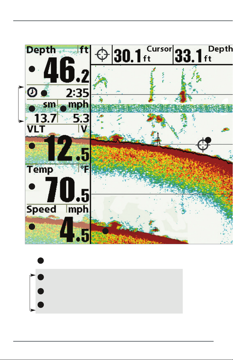
Depth - Water depth can be set to alarm when the water becomes too shallow.
Timer - Elapsed time with Speed accessory or GPS receiver
.
13
3
Distance - Distance traveled with Speed accessory or GPS receiver
Triplog
4
Average Speed - Average speed reading with Speed accessory or GPS receiver
What’s on the Sonar Display
.
.
18
Page 25
your boat, including the following items:
10
8
11
(HELIX SONAR GPS, HELIX DI GPS, HELIX XD GPS only)
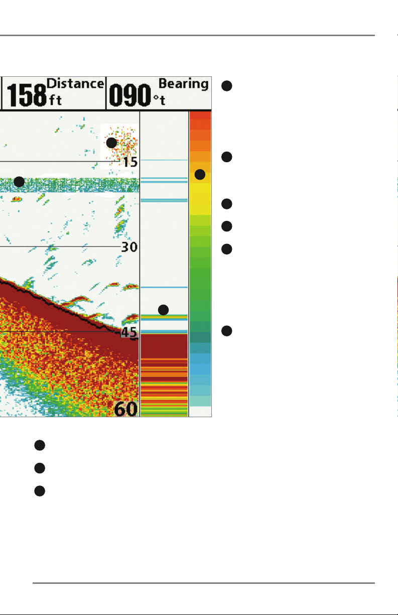
8
Thermoclines - Layers of water with different
temperatures that appear at different depths and
different times of the year. A thermocline typically
appears as a continuous band of many colors
moving across the display at the same depth.
9
Sonar Color Bar - Color spectrum indicating low
9
to high sonar intensity returns, where red indicates
high intensity and white indicates low intensity.
10
Bait Ball
11
RTS (Real Time Sonar) Window
12
Second Sonar Return - When the sonar signal
bounces between the bottom and the surface of the
water and back again. Use the appearance of the
second return to determine bottom hardness. Hard
bottoms willshow a strongsecond return, whilesoft
bottoms will show a very weak one or none at all.
5
Voltage - Power supplied to the control head.
6
Temperature - Water surface temperature.
7
Speed - If a Speed accessory or GPS receiver is connected,
the Fishfinder can display the speed of the boat, and can
keep a triplog of nautical or statute miles traveled.
19
13
Cursor - Available in Freeze Frame and can be
positioned in the Sonar View to provide depth of a
sonar returnand bottom depth below thecursor. The
Latitude and Longitude of the cursor position, the
distance to travel to the cursor position, and the
bearing to the cursor position are shown with a
connected GPS receiver. Cursor information is
displayed at the top of the screen.
What’s on the Sonar Display
Page 26
Understanding the Sonar Display
It is important to understand the significance of the display. The
display does NOT show a literal 3-dimensional representation of
what is under the water. Each vertical band of data received by the
control head and plotted on the display represents something that
was detected by a sonar return at a particular time. As both the
boat and the targets (fish) may be moving, the returns are only
showing a particular segment of time when objects were detected,
not exactly where those objects are in relation to other objects
shown on the display.
The returned sonar echoes are displayed on the screen. As a new
echo is received, the historical data scrolls left across the display.
Real Time Sonar (RTS) Window
A Real Time Sonar (RTS) Window appears on the right side of the display in the Sonar Views only.
The RTS Window always updates at the fastest rate possible for depth conditions and shows only
the returns fromthe bottom, structure and fish that are within the transducer beam. The RTS Windo w
plots the depth and intensity of a sonar return. (See Sonar Menu Tab: Real Time Sonar (RTS)
Window).
The Narrow RTS Window
indicates the sonar intensity
through the use of colors.
Red indicates a strong return
and blue indicates a weak
return. The depth of the
sonar return is indicated by
the vertical placement of the
return on the display depth
scale.
The Wide RTS Window
indicates the sonar intensity
through the use of a bar
graph. The length of the
plotted return provides an
indication of whether the
return is weak or strong. The
depth of the sonar return is
indicated by the vertical
placement of the return on
the display depth scale. The
Wide RTS Window does not
use grayscale.
What’s on the Sonar Display
20
Page 27
Sonar Colors: Original Palette
HIGH
Intensity Return
MEDIUM
Intensity Return
LOW
Intensity Return
Sonar Colors and Bottom View
As the boat moves, the unit charts the changes in depth on
the display to create a profile of the Bottom Contour.The
Sonar View displays the sonar return intensity with different
colors.
Strong returns often result from rocky or hard bottoms
(compacted sediment, rocks, fallen trees), while weaker
returns often result from soft bottoms (sand, mud), vegetation,
and small fish.
The colors used to represent high, medium, to low intensity
returns are determined by the palette you choose in the Sonar
Colors menu option. See Sonar Menu T ab to set the Sonar
Colors.
Sonar View: Original Palette
1
3
2
Sonar History: Historical returns scroll left across the view Strong Return (possibly compacted sediment or rocks)
1
Strong Returns (possibly rocks, tree limbs, or other structure)
2
Weak Returns (possibly vegetation or small fish)
3
21
What’s on the Sonar Display
5
4
RTS Window
4
5
Page 28
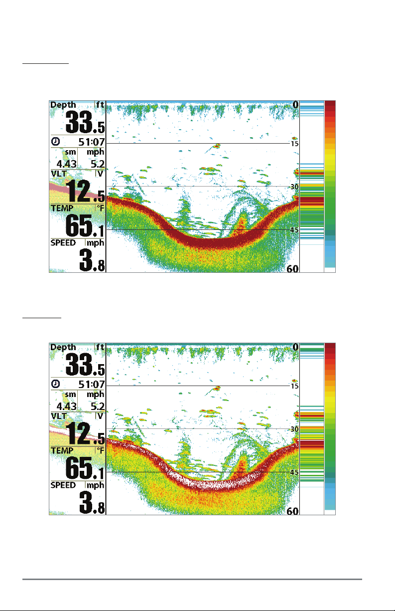
Use Bottom View to select the method used to represent bottom and structure on the display.
See Sonar Menu to set the Bottom View.
Structure ID
represents weak returns in blue and strong returns in red when Sonar Colors is set
to Original. If the Sonar Colors palette is changed, the Structure ID will display the strongest
return as specified by the palette. See Sonar Menu T ab: Sonar Colors for more information.
WhiteLine
highlights the strongest sonar returns in white, resulting in a distinctive outline. This
has the benefit of clearly defining the bottom on the display.
What’s on the Sonar Display
22
Page 29

SwitchFire
SwitchFire controls how the sonar returns are displayed in the Sonar Views. SwitchFire settings
are available in the Sonar Menu Tab.
To see the maximum sonar information available within the transducer beam so more fish
arches and better jig tracking are shown, choose Max Mode.
To see less clutter and more fish size accuracy interpreted from the transducer beam, choose
Clear Mode. See Sonar Menu Tab: SwitchFire for more information.
Freeze Frame and Active Cursor
Freeze Frame & Active Cursor - Press any arrow on the 4-WAY Cursor Control key, and the
screen will freeze and a cursor will be displayed. Use the 4-WAY Cursor Control key to move the
cursor over a sonar return, and the depth of the sonar return will be displayed in the cursor
dialog box.
The RTS Window continues to update in Freeze Frame. To return to a scrolling display and exit
Freeze Frame, press the EXIT key. Freeze Frame is available in the Sonar, Split Sonar, and Sonar
Zoom Views.
Instant Image Update
Instant Image Update - You can change a variety of sonar menu settings (such as Sensitivity
or Upper Range), and the adjustments will be shown instantly on the screen.
23
What’s on the Sonar Display
Page 30
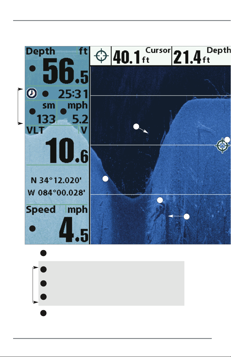
What’s on the Down Imaging Display
Down Imaging uses unique sonar technology to provide information about the area directly
that you see on the display. Down Imaging reveals a variety of recognizable features so that you
1
2
Tri p log
3
4
13
10
12
5
1
Depth - Water depth can be set to alarm when the water becomes too shallow.
2
Timer - Elapsed time with Speed accessory or GPS receiver
3
Distance - Distance traveled with Speed accessory or GPS receiver
Triplog
4
Average Speed - Average speed reading with Speed accessory or GPS receiver
5
Speed - If a GPS Receiver or Temp/Speed accessory is connected, the Fishfinder can
display thespeed of the boat and can keep aTriplog ofnautical or statute miles traveled.
What’s on the Down Imaging Display
8
9
.
.
.
24
Page 31

(HELIX DI GPS only)
below your boat. The razor-thin, high- definition profiling beams produce the detailed sonar data
can interpret the structure and bottom contour, including the following items:
9
Shadows - Result from a lack of reflected sonar
from a particular area and can be as valuable for
interpretation than the sonar reflected by the object
6
itself. Use shadows to help you see the image in 3
dimensions, oriented in space. You can gain insight
into the actual shape of an object, or the depth to
which it has sunk into the bottom, through shadows
11
on the display. Objects standing on the bottom cast a
sonar shadow. The longer the shadow, the taller the
object. Fish also cast shadows. You can use the
shadow to interpret how close the fish is to the
bottom.
10
Topography Changes - The light part of the
display shows wherethe beam is hitting hard bottom
or rising terrain. The dark part of the display indicates
soft bottom (sand, mud) or descending terrain.
11
Bottom Return - Use the appearance of the
bottom return to determine bottom hardness. Rock
and gravel provide a clearer sonar return than mud
and sand because hard objects reflect sonar better
than soft objects.
12
Freeze Frame - Use the 4-WAY Cursor Control key
to move the cursor to an area on the screen.
13
Clouded Area may indicate a bait ball and White
7
6
Upper Range
7
Lower Range
8
Structure
NOTE: Entries in this view that list (with Temp/Speed or GPS Receiver) are available if either device is
connected to the control head. If both devices are connected, then only the information from the GPS
receiver will be displayed on the view.
25
Streaks may indicate fish.
What’s on the Down Imaging Display
Page 32

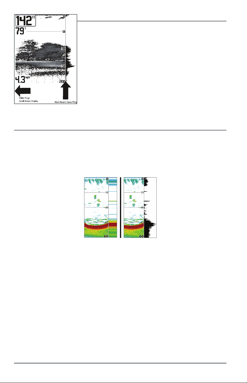
Understanding the Down Imaging Display
The images you see on the Down Imaging display are
produced using sonar technology. Each time the unit
pings, a strip of data representing all the echoes
received by the transducer are put together on the
display to form the image that you see. Like traditional
2D Sonar, the sonar history scrolls left across the
screen.
Interpreting the Display
Down Imaging beams “illuminate” the bottom contour, structure, and fish. The beams are wide
(side to side) but very thin front to back.
Use the light and dark parts of the display to interpret the objects under your boat as follows:
• Dark shades represent soft returns (mud, sand) or descending terrain.
• Light shades represent denser terrain (timber, rocks) or rising terrain. A very hard bottom
may appear as white on the display.
• White Streaks or Clouds may represent fish on the display.
• Shadows are not caused by light but by the lack of a sonar return. Objects standing on
the bottom cause a sonar shadow to appear on the display. The longer the shadow, the
taller the object. Fish may also cast shadows. You can use the shadow to interpret where
the fish or object is located in relation to the bottom.
Down Imaging Sensitivity
Use Down Sensitivity to control how the sonar returns appear on the display. Increase the
sensitivity to reveal weaker returns that may be of interest, especially in very clear water or greater
depths. Decrease the sensitivity to eliminate the clutter from the display that is sometimes present
in murky or muddy water. See the Down Imaging X-Press Menu for more information.
Freeze Frame and Active Cursor
Freeze Frame and Active Cursor - Press any arrow on the 4-WAY Cursor Control key, and the
screen will freeze and a cursor will be displayed. Use the 4-WAY Cursor Control key to move the
cursor over a sonar return, and the depth of the sonar return will be displayed in the cursor dialog
box.
Zoom: Use the zoom keys on your control head to see the returns near the cursor location at a
higher magnification. See Views: Down Imaging View for more information.
What’s on the Down Imaging Display
26
Page 33

Views
The sonar and navigation information from your control head is displayed on
the screen in a variety of easy-to-read views.
Select a View
The available views on your Humminbird unit will vary with the model you’ve purchased and, if it’s
a sonar model, the transducer attached to the control head. See Views Menu T ab and the following
pages for more information.
Next View: Press the VIEW key to advance to the next view in the View
Rotation. Press the VIEW key repeatedly until the view you want to use
is displayed on the screen.
Previous View: Press the EXIT key to see the previous view in the View
Rotation. Press the EXIT key repeatedly until the view you want to use is
displayed on the screen.
Display your Favorite Views
You can display or hide any view so that each time you press the VIEW key, only your favorite
views are displayed on the screen.
1. Press the MENU key twice to open the Main Menu.
2. Press the RIGHT Cursor key until the Views tab is selected.
3. Press the UP or DOWN Cursor keys to select a view.
4. Press the LEFT or RIGHT Cursor keys to select Hidden or Visible.
27
Views
Page 34

Change Digital Readouts
Each view displays digital readout information (such as speed or time), which varies with the
view displayed on-screen, connected accessories, and whether or not you are navigating.
Sonar View
1
2
3
4
5
1
Readout 1
2
Readout 2
HELIX SONAR GPS, HELIX DI GPS, HELIX XD GPS: In Sonar View and Down Imaging View,
you can choose which digital readouts you want to display. In the Chart View and Bird’s Eye
View, certain digital readouts can be customized and others are fixed, depending on whether or
not you are navigating. See Setup Menu Tab: Select Readouts for more information.
HELIX GPS: You can select digital readouts for non-navigation mode (Select Readouts) and
navigation mode (Select Nav Readouts). The Select Nav Readouts menu option allows you to
choose standard digital readouts (such as Time or Voltage) and navigation digital readouts. See
Navigation X-Press Menu: Select Readouts and Select Nav Readouts for more information.
3
4
Readout 3
Readout 4
5
Readout 5
1. HELIX SONAR GPS, HELIX DI GPS, HELIX XD GPS: Press the MENU key twice to open
the Main Menu. Press the RIGHT Cursor key until the Setup tab is selected.
NOTE: If the Select Readouts option does not appear under the Setup Tab, change the User Mode
to Advanced (Setup tab > User Mode > Advanced).
HELIX GPS: Press the MENU key once. The available menu options will be displayed for
the on-screen view.
2. Press the DOWN key to highlight Select Readouts or Select Nav Readouts (HELIX GPS
only), and press the RIGHT Cursor key.
3. Press the UP or DOWN Cursor keys to select a Readout window. Press the RIGHT or LEFT
Cursor keys to choose a digital readout.
Blank: To hide a data window, select Off.
Views
28
Page 35

Digital Readouts (Selectable or Fixed)
Bearing Bearing is the direction to a destination waypoint measured in degrees from North (i.e. 321°, where 000° is
CMG/SMG Course MadeGood/Speed Made Good. Course Made Good is the angle between the startingpoint on a route and
COG Course Over Ground. Course Over Ground is the current direction the boat is traveling measured in degrees from
Off Suppresses the readout so that no data shows in that position.
Position Position is the current location (latitude, longitude) determined by GPS.
SOG Speed Over Ground. Speed Over Ground is the measurement of the boat’s progress across a given distance; the
TRK/CMG Track/CourseMade Good.The Track Line is thedesired lineof travelbetween twowaypoints, andrepresents themost
TTG Time ToGo. Time To Go is the estimated time required to reach the destination waypoint. TTG is calculated using
Temp The current detected water temperature.
Aux. Temp The currentdetected water temperature from an optional-purchase Temperature Probe or Temp/Speed accessory.
Time The current time.
Time + Date The current time and date.
Triplog Displays thetriplog, which measures the elapsedtime since last reset, thedistance traveled since last reset, and
VMG Velocity Made Good. Velocity Made Good is the speed of travel relative to the next waypoint on the route. The
Voltage Power supplied to the control head.
WPTend/ETA/DTG Waypoint End/Estimated Time of Arrival/Distance to Go. Waypoint End is the last waypoint on the route.
WPTend/TTG/DTG Waypoint End/Time To Go/Distance to Go. Waypoint End is the last waypoint on the route. Time To Go is the
Water Speed The current speed of the water as it flows past the boat.
WPTnext/ETA/DTG Waypoint Next/Estimated Time of Arrival/Distance to Go. Waypoint Next is the next waypoint on the route.
WPTnext/TTG/DTG Waypoint Next/Time To Go/Distance to Go. Waypoint Next is the next waypoint on the route. Time To Go is the
Waypoint/TTG Waypoint/Time To Go. Waypoint/TimeTo Go for the next waypoint on the route.
XTE Cross Track Error isthe straight-line distance of the boat from the intended Track. XTE measures how far the boat
North, 090° East, 180° is South, 270° is West).
the currentposition of the boat. Thegoal is to have CMG and Trackequal to the same number. Speed MadeGood
is the distance from the starting waypoint on the route divided by the time elapsed since starting navigation on
the route.
North (i.e. 321°, where000° isNorth, 090° East, 180° is South, 270° is West). When the Course Over Ground
is equal to Bearing, the boat is said to be “On Course” and will arrive at the destination in the most efficient
manner.
speed measurement provided by GPS; accurate destination times can be derived from this measurement.
efficient path between the twopoints because it is a straight line. TheTRK is measured in degrees. See above for an
explanation of Course Made Good.
the SOG and DTG.
average speed during timed interval.
goal is for VMG to equal Speed.
Estimated Time of Arrival is the estimated time of arrival to the last waypoint on the route. Distance To Go is the
distance between the current position of the boat and the last waypoint on the route.
estimated time required to reach the lastwaypoint onthe route.TTG is calculated using the SOG and DTG. Distance
To Go is the distance between the current position of the boat and the last waypoint on the route.
Estimated Time of Arrival is the estimated time of arrival to the next waypoint on the route. Distance To Go is the
distance between the current position of the boat and the next waypoint on the route.
estimated time required to reach the next waypoint on the route. TTG is calculated using the SOG and DTG.
Distance To Go is the distance between the current position of the boat and the next waypoint on the route.
is off course, and also triggers the Off Course Alarm.
29
Views
Page 36

Combo Views
Combo Views display two views (or more) on the screen at the same time. You can perform
functions for either side of the view, access the X-Press Menu, and change the left view display
size. The available combo views are determined by your Humminbird model.
To change the settings for either side of the view, the individual view must be selected as the
active side.
•Thegreen arrow points to the active side.
• Active Side: Press the MENU key once and select Active Side from the X-Press Menu.
Choose RIGHT or LEFT to set the active side.
• X-Press Menu: After you set the Active Side, press the MENU key once to open the
X-Press Menu. The X-Press Menu provides settings for the active view, and the display
updates immediately with your changes.
• Display Size: Press the MENU key once and select Split Position from the X-Press Menu.
Split Position allows you to adjust the size of the left side of the display.
• Active Cursor: Press any arrow on the 4-WAY Cursor Control key, and the cursor will
appear on the active side of the view.
1
green arrow = active side
1
Views
30
Page 37

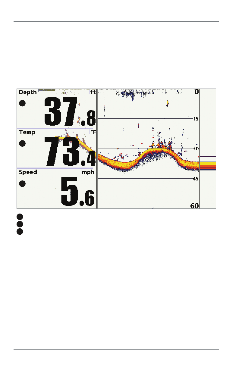
Sonar View (HELIX SONAR GPS, HELIX DI GPS, HELIX XD GPS only)
Sonar View presents a historical log of sonar returns. The most recent sonar returns are charted
on the right side of the display. As new information is received, the historical information scrolls
left across the display.
• Upper and Lower Depth Range numbers indicate the distance from the surface of the
water to a depth range sufficient to show the bottom.
• Depth is automatically selected to keep the bottom visible on the display, although you
can adjust it manually as well (see Sonar X-Press Menu).
• Digital Readouts shown on the display will change based on the Select Readouts settings
or the optional-purchase accessories attached (see Views: Change Digital Readouts).
• Freeze F r ame: Use the 4-WAY Cursor Control key to freeze the display and mov e the cursor
over a sonar return. The depth of the sonar return will be displayed in the cursor dialog
box.
Sonar View
6
1
2
3
4
Depth Depth Below Cursor
1
Triplog
2
Temperature
3
Speed
4
Cursor
5
Depth of Cursor
6
7
5
8
9
10
12
Distance to Cursor
Bearing to Cursor
RTS Window
Sonar Color Bar
Lower Depth Range
NOTE: If the Depth number is flashing, it means that the unit is having trouble locating the bottom. This
usually happens if the water is too deep, the transducer is out of the water, the boat is moving too fast, or
for any other reason that the unit can’t accurately receive continuous data.
11
7
8
9
10
11
12
31
Sonar Views
Page 38

Sonar Zoom View (HELIX SONAR GPS, HELIX DI GPS, HELIX XD GPS only)
Sonar Zoom View provides a magnified view of the bottom and structure. The Sonar Zoom View
makes it easier to see separate sonar returns that would usually be displayed close together,
such as those caused by fish suspended close to the bottom or within structure.
•TheZoom Level, or magnification, is displayed in the top left corner of the display. Press
the + or - ZOOM keys to increase or decrease the zoom level.
•TheZoomed View is displayed on the left side of the screen. As the depth changes, the
zoomed view updates automatically.
•TheFull Range View is displayed on the right side of the screen. The Full Range View
includes the Zoom Preview Box, which shows where the zoomed view is in relation to
the full range view.
•TheUpper and Lower Depth Range numbers indicate the high and low range of the
water which is being viewed.
• Digital Readouts shown on the display will change based on the Select Readouts settings
or the optional-purchase accessories attached (see Views: Change Digital Readouts).
• Freeze F r ame: Use the 4-WAY Cursor Control key to freeze the display and move the cursor
over a sonar return. The depth of the sonar return will be displayed in the cursor dialog
box.
Sonar Zoom View
1
2
3
4
1
Depth
2
Triplog
3
Temperature
4
Speed
5
Zoomed View
6
Zoom Level
Sonar Views
6
5
8
10
9
Upper Depth Range, Full Range View
Upper Depth Range, Zoom View
Zoom Preview Box
Full Range View
Lower Depth Range, Full Range View
Lower Depth Range, Zoom View
7
1112
7
8
9
10
11
12
32
Page 39
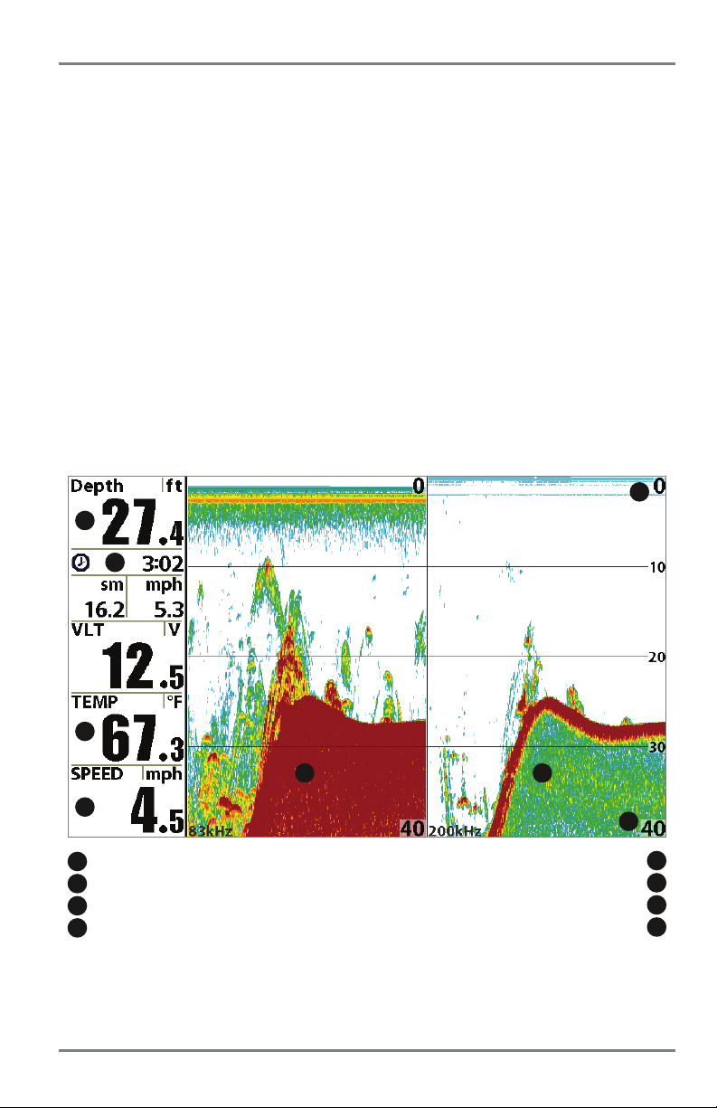
Split Sonar View (HELIX SONAR GPS, HELIX DI GPS, HELIX XD GPS only)
Split Sonar View displays sonar returns from each down beam frequency on separate sides of
the screen. You can use the Split Sonar View to make side by side comparisons between the
sonar returns from both beams.
• DualBeam PLUS models (HELIX SONAR GPS) display sonar returns from the 83 kHz
wide beam on the left side of the screen and sonar returns from the 200 kHz narrow beam
on the right side of the screen.
• Down Imaging models (HELIX DI GPS) display traditional 2D sonar returns from the 455
kHz narrow beam on the left side of the screen and sonar returns from the 200 kHz wide
beam on the right side of the screen.
• Xtreme Depth models (HELIX XD GPS) display sonar returns from the 50 kHz wide beam
on the left side of the screen and sonar returns from the 200 kHz narrow beam on the right
side of the screen.
• Freeze F r ame: Use the 4-WAY Cursor Control key to freeze the display and move the cursor
over a sonar return. The depth of the sonar return will be displayed in the cursor dialog
box.
Split Sonar View (HELIX SONAR GPS)
5
1
2
3
8
4
1
Depth Upper Depth Range
2
Triplog
3
Temperature
4
Speed
7
Lower Depth Range
200 kHz Sonar History Window
83 kHz Sonar History Window
33
6
5
6
7
8
Sonar Views
Page 40
Big Digits View (HELIX SONAR GPS, HELIX DI GPS, HELIX XD GPS only)
Big Digits View provides digital data in a large, easy-to-see format.
• Digital Readouts: Readouts for depth, temperature, and speed information are displayed
automatically if the transducer with built-in temperature and GPS receiver are connected
to the Fishfinder.
• The digital readouts in the Big Digits View cannot be customized.
Big Digits View
1
2
3
1
Depth
2
Temperature
3
Speed
Sonar Views
34
Page 41

Circular Flasher View (HELIX SONAR GPS, HELIX DI GPS, HELIX XD GPS only)
Circular Flasher View provides two ways to view sonar data in traditional flasher format. The view
is controlled by the Ice Fishing Mode menu option in the Sonar Menu Tab.
• When Ice Fishing Mode is off, the Circular Flasher View displays Real Time Sonar (RTS)
data in a traditional flasher format.
• When Ice Fishing Mode is on, the Circular Flasher View displays the sonar data in
traditional flasher format with additional features including Zoom and Depth Cursor.
Set the Circular Flasher View Mode
1. Press the MENU key twice.
2. Press the RIGHT Cursor key until the Sonar Menu Tab is selected.
3. Press the DOWN Cursor Key to select Ice Fishing Mode. Press the RIGHT or LEFT Cursor
key to select On or Off (Default = Off). See Sonar Menu T ab for more information.
Set the Digital Depth Source (Down Imaging models only)
If you connect an ice transducer to the control head, set the Digital Depth Source to 2D Element
to display depth in the digital readout window. See Sonar Menu Tab: Digital Depth Source for
more information.
1. Press the MENU key twice.
2. Press the RIGHT Cursor key until the Sonar Menu Tab is selected.
3. Press the DOWN Cursor Key to select Digital Depth Source. Press the RIGHT or LEFT
Cursor key to select 2D Element.
35
Sonar Views
Page 42

Ice Fishing Mode: Off
When Ice Fishing Mode is off, the Circular Flasher View displays Real Time Sonar (RTS) data
in a traditional flasher format.
• Flasher X-Press Menu: Press the MENU key once in the Circular Flasher View. Use the
X-Press Menu to set the Sensitivity, Upper Range, and Lower Range.
• Depth and temperature are always displayed.
•TheDigital Readouts cannot be customized.
Circular Flasher View (Ice Fishing Mode: Off)
1 2
1
Flasher Dial
Sonar Views
36
Depth
2
Page 43

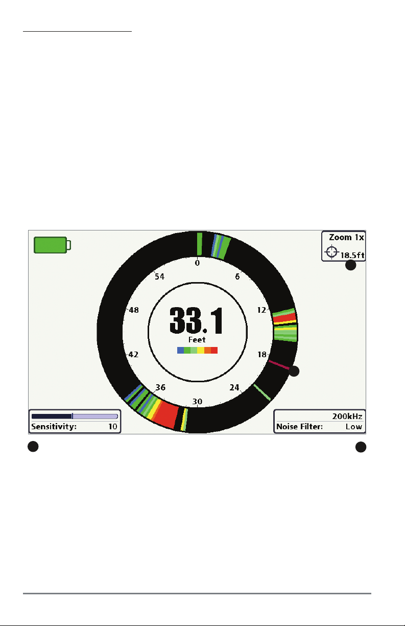
Ice Fishing Mode: On
When Ice Fishing Mode is on, the Circular Flasher View displays the sonar data in traditional
flasher format with additional features including Zoom and Depth Cursor.
• Sensitivity: When you turn on Ice Fishing Mode, the fishfinder’s sensitivity settings are
adjusted automatically to accommodate ice fishing conditions. These settings will apply
to the other Sonar Views until you turn off Ice Fishing Mode (see Set the Circular Flasher
View Mode in this section).
• Flasher X-Press Menu: Press the MENU key once in the Circular Flasher View. Use the
X-Press Menu to set the Sensitivity, Upper Range, Lower Range, and Color Palette.
• Color Palettes: The color preview bar in the center of the display indicates the current
palette, and the weak to strong sonar return range is displayed from left to right. To
change the color palette, see Flasher X-Press Menu: Color Palette.
• The Digital Readouts cannot be customized.
Circular Flasher View (Ice Fishing Mode: On)
1
2
5
1
Battery Icon (percentage of battery power)
2
Flasher Dial
3
Depth
4
Color Palette
6
3
4
7
8
Sensitivity (see Flasher X-Press Menu)
Zoom Setting
Beam Select (see Sonar Menu Tab)
Noise Filter (see Sonar Menu Tab)
5
6
7
8
37
Sonar Views
Page 44
To activate the Depth Cursor:
Use the Depth Cursor to identify depth on the flasher display.
1. Set up: Press the VIEW key repeatedly until the Circular Flasher View is displayed on the
screen. Turn on the Ice Fishing Mode (see Sonar Menu Tab).
2. Activate: Press the DOWN Cursor key, and the purple cursor line will appear on the
display.
3. Adjust the Cursor: Press the UP or DOWN Cursor keys repeatedly until you reach the
chosen depth reading. The depth reading of the cursor is displayed in the top, right corner
of the view.
4. Close the Cursor: Press the EXIT key.
Circular Flasher View with Depth Cursor
1
1
Depth Cursor Reading
NOTE: See Set the Digital Depth Source for more information.
Sonar Views
38
2
Depth Cursor
2
Page 45

To activate Flasher Zoom:
The Zoom feature displays a 2x magnified view of the area you choose on the flasher display.
1. Set up: Press the VIEW key repeatedly until the Circular Flasher View is displayed on the
screen. Turn on the Ice Fishing Mode (see Sonar Menu Tab).
2. Activate: Press the +ZOOM key. The Zoom upper limit and lower limit lines will appear
on the display.
3. Adjust the Zoom Range: Press the RIGHT or LEFT Cursor keys repeatedly to adjust the
zoom range and select the area you want to magnify. The zoomed view is shown on the
right side of the flasher dial between two lines. The normal view is shown on the left side
of the flasher dial.
4. Close Zoom: Press the − ZOOM key.
Circular Flasher Zoom
normal view
(reading the full depth of the water column)
zoom line
(upper limit)
zoom line
(lower limit)
zoom view
(2X magnification)
39
Press the RIGHT or LEFT
Cursor key to change the
Zoom Range.
Sonar Views
Page 46

Down Imaging View (HELIX DI GPS only)
Down Imaging View uses the razor-thin, high-definition profiling beams to produce the detailed
sonar data that you see on the display. Sonar returns are charted on the right side of the display.
As new information is received, the historical information scrolls left across the display. See
What’s on the Down Imaging Display for more information.
• Down Imaging X-Press Menu: Press the MENU key once to access the Down Imaging
X-Press Menu. You can set the sensitivity of the sonar to see more or less detail, the chart
scrolling speed, and the display color palette (see Down Imaging X-Press Menu).
• Freeze Frame: Press any arrow on the 4-WAY Cursor Control key, and the
Down Imaging View will freeze and a cursor will appear on the screen. Use the 4-WAY
Cursor Control key to move the cursor over a sonar return, and observe the following:
-Thedepth of the sonar return you choose will be displayed in the cursor information
box.
- Zoom+: Press the ZOOM+ key, and a zoom box will appear and magnify the area you
choose, providing more detail in the individual sonar returns. The zoom scale will
increase or decrease as you press + or - repeatedly. Press EXIT to remove the zoom
box and return to Down Imaging View.
Down Imaging View
8
1
2
3
4
5
1
Depth
2
Triplog
3
Water Surface Temperature
4
Time
5
Speed
Sonar Views
6
7
9
Bottom Return
Topography Changes
Upper Range
Lower Range
6
7
8
9
40
Page 47

Down Imaging View with Active Cursor and Zoom
6
1
2
3
4
5
1
Depth
2
Water Surface Temperature
3
Voltage
4
Triplog
5
Speed
7
8
9
Cursor Dialog Information
Zoom Magnification Box
Zoomed View
Lower Range
NOTE: To change the colors used to display the Down Imaging data on the screen, see Down Imaging
X-Press Menu: DI Colors.
6
7
8
9
41
Sonar Views
Page 48

Snapshot and Recording View
(optional-purchase microSD Card required)
Snapshot and Recording View displays the screen snapshots and recordings that are saved on
the optional-purchase microSD card installed in the control head. Use this view to review the
snapshot and recording file details, start recording, and adjust the recording settings.
NOTE: The recording feature is only available in Humminbird models with sonar. You can take screen
snapshots with the HELIX GPS, but the recording feature is not available on this model.
• Activate Screen Snapshot: Select Screen Snapshot from the Setup Menu Tab, and select
On. Also, install an optional-purchase microSD card in the control head, and make sure
Snapshot and Recording View is set to Visible on the Views Menu Tab.
• Scroll and View: Use the UP and DOWN Cursor keys to scroll through the saved Screen
Snapshots and Recordings. The active file is highlighted with arrows. Press the RIGHT
Cursor key to view the file.
• Snapshot and Recording X-Press Menu: Press the MENU key once in this view to open
the X-Press Menu. Use the X-Press Menu to Start Recording, Delete Images, or adjust
the Recording and Playback settings (see Recording and Playback or Snapshot and
Recording X-Press Menu).
Snapshot and Recording View
1
3
2
1
Recording icon
2
Snapshot thumbnail
3
Unavailable icon
4
Information box
Snapshot and Recording View
4
5
6
7
Amount of recording left to play
Amount of recording that has been played
Amount of space used for this recording
5
8
Recording mode icons
5
6
7
8
42
Page 49

Screen Snapshots
Screen Snapshots are saved pictures of the view on the screen. The screen snapshot will include
the menus, dialog boxes, warnings, and messages that were active when the screen snapshot
was taken. Saved Screen Snapshots can be viewed from the Snapshot and Recording View or
Chart View.
The Screen Snapshot feature is available when an optional-purchase microSD card is installed and
Screen Snapshot is On (see Setup Menu Tab: Screen Snapshot).
2
1
Waypoint Saved at Cursor Location
2
Screen Snapshot Confirmation
3
File Name
1
From Snapshot and Recording View,
select Delete Image from the X-Press Menu.
Make a Screen Snapshot
:
1. Activate Screen Snapshot and install a
1
microSD card.
2. From any view or cursor location you want
3
to capture, press the MARK key. The screen
will pause while the image is saved.
A waypoint will also be created at the boat or
active cursor location. The screen snapshot
shares the same file name (.PNG).
Delete a Screen Snapshot:
1
1. From the Snapshot and Recording View,
press the UP or DOWN Cursor keys to scroll
through the saved files and highlight a
snapshot file.
2. Press the Menu key once, and select Delete
Image from the X-Press Menu.
3. Press the RIGHT Cursor keys.
NOTE: Navigation is not affected by the Screen Snapshot feature. Also, if Screen Snapshot is enabled,
but a GPS receiver is not connected, pressing the MARK key will capture the screen image but an error
will display that says a GPS position fix is required to create a waypoint.
43
Snapshot and Recording View
Page 50

4
1
Snapshot File Name
2
Time + Date of Snapshot
3
Waypoint Position
4
Highlighted Snapshot File
5
microSD card available storage
1 2
View a saved Screen Snapshot from Snapshot
and Recording View:
3
1. From the Snapshot and Recording View,
press the UP or DOWN Cursor keys to scroll
through the saved files and highlight a
snapshot file.
5
2. Press the RIGHT Cursor key.
View a sav ed Screen Snapshot from Chart View:
1. In Chart View, use the 4-WAY Cursor Control
1
key to move the active cursor onto a Screen
Snapshot Icon .
2
When the cursor snaps onto the Screen
Snapshot Icon, a thumbnail preview of the
Screen Snapshot will be displayed on the
1
Screen Snapshot Icon and Waypoint Name
Thumbnail Preview
2
(press the CHECK/INFO key to view at full size)
screen.
2. Press the CHECK/INFO key, and select View
Snapshot.
3. Press the EXIT key to return to Chart View.
Notes about Screen Snapshots
:
•Aborder around the full screen indicates that the view is a saved screen snapshot and
not a “live” view.
• If you press the CHECK/INFO key, and the snapshot file connected to the icon is not
saved on the installed microSD card, the Chart Information box will display instead of the
screen snapshot.
• Use an optional-purchase microSD card adapter connected to a PC to view the saved
screen snapshot data files on your optional-purchase microSD Card (see humminbird.com
for details). You will notice that a .DAT (or a .TXT) file is created for every .PNG screen
snapshot. This data file is required for viewing the screen snapshots from your control
head, so don’t delete these files.
Snapshot and Recording View
44
Page 51

Recording and Playback
The Recording feature records active sonar information. When the recording is played back, the
views that were active during the recording are available in Playback. The Recording and
Playback feature is available when an optional-purchase microSD card is installed and Screen
Snapshot is On (see Setup Menu Tab: Screen Snapshot). Saved Recordings can be played back
from the Snapshot and Recording View.
NOTE: The recording feature is only available in Humminbird models with sonar. The recording feature
is not available in the HELIX GPS model.
1
Start recording
:
1. From the Snapshot and Recording View,
press the MENU key once to open the
Snapshot and Recording X-Press Menu.
2. Highlight Start Recording, and press the
RIGHT Cursor key. A waypoint will also be
1
From Snapshot and Recording View,
select Start Recording from the X-Press Menu
2
Slider Bar
2
created at the boat location, and the
recording shares the same file name (.SON).
Stop recording
:
1. In any view, press the MENU key once to
open the Snapshot and Recording X-Press
Menu.
2. Highlight Stop Recording and press the
RIGHT Cursor key.
Notes about Recording:
• While recor ding, press the EXIT key to exit the Snapshot and Recording X-Press Menu and
scroll to a different view. Recording will continue.
•Theslider bar at the bottom of the Snapshot and Recording View shows the recording
progress and remaining space on the microSD card.
• Pings Per Second: For maximum performance, keep the Pings Per Second setting on
Auto (see Snapshot and Recording X-Press Menu).
• Viewing saved Screen Snapshots and Recording Playback are not available while in
recording mode.
45
Snapshot and Recording View
Page 52
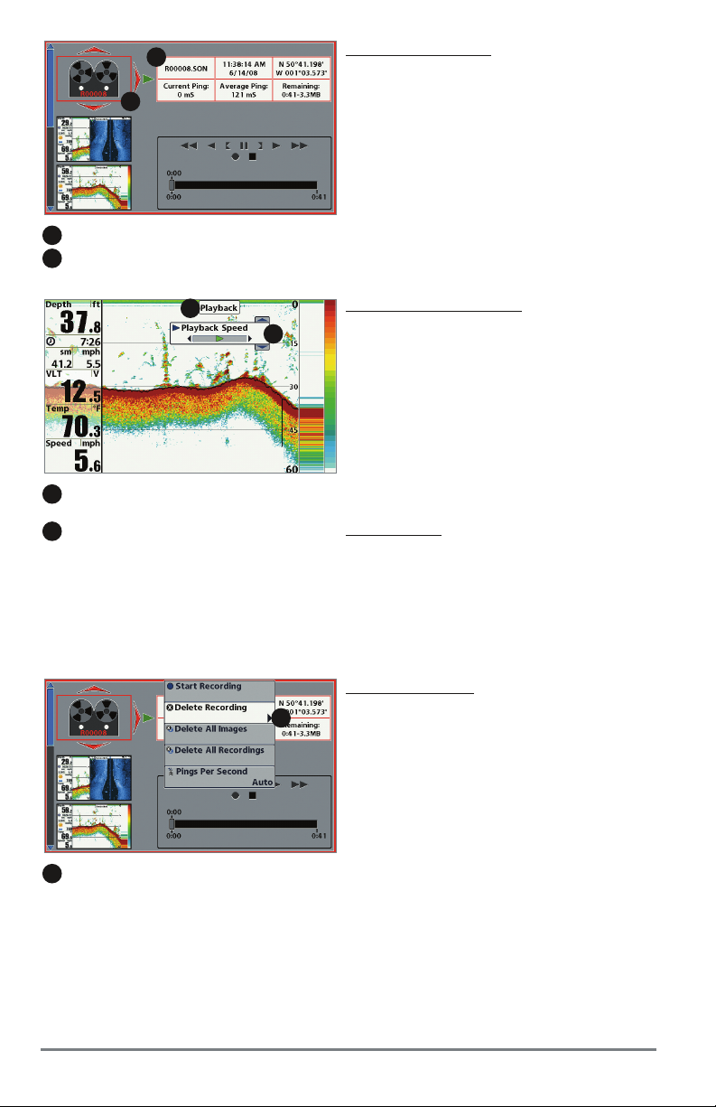
2
1
Recording File Information
2
Highlighted Recording File
1
Playback a Recording:
1. From the Snapshot and Recording View,
press the UP or DOWN Cursor keys to scroll
through the saved files and highlight a
saved Recording.
2. Press the RIGHT Cursor key.
1
1
“Playback” indicates the control head is playing
a saved recording.
2
Open the X-Press Menu to adjust Playback settings.
You can also use Freeze Frame and mark waypoints.
1
From Snapshot and Recording View,
select Delete Recording from the X-Press Menu.
Change Playback Settings:
2
1. Press the MENU key once to open the
Snapshot and Recording X-Press Menu.
2. Use the X-Press Menu to adjust the Sonar
Recording’s Sensitivity , Upper Range, Lower
Range, and the Playback Speed. See
Snapshot and Recording X-Pr ess Menu for
details.
Stop Playback:
1. Press the MENU key once to open the
Snapshot and Recording X-Press Menu.
2. Highlight Stop Playback, and press the
RIGHT Cursor key.
Delete a Recording:
1
1. From the Snapshot and Recording View,
press the UP or DOWN Cursor keys to scroll
through the saved files and highlight a
saved Recording.
2. Press the Menu key once, and select Delete
Recording from the X-Press Menu. Press the
RIGHT Cursor key.
Snapshot and Recording View
46
Page 53

Notes about Playback:
• “Playback” will flash periodically on the screen to indicate that the control head is playing
a saved recording and not a “live” view.
• Navigation is not affected by the Sonar Recording feature, but any active navigation is
cancelled and thumbnails and icons disappear when Playback begins or ends.
• Playback is paused automatically at the end of the recording.
• Freeze F rame: Press the 4-WAY Cursor Control key to pause Playback and move the Active
Cursor to a location on the sonar view. The Cursor dialog box will show the depth and
information for the location you choose. Press Exit to resume Playback.
• Press the MARK key during Playback to save a Screen Snapshot and/or mark a waypoint
in the view or active cursor location you choose.
Recording Information
1
1
Recording Indicator
2
Amount of space and time used by this recording
3
Name of recording
4
Time and Date recording was started
5
Position where recording was started
3 4
6 7 8
2
Average Ping Rate
Amount of space remaining on card
Total amount of space on card
5
9
Current Ping Rate
NOTE: Sonar chart speed is increased during Fast Forward and reversed during Rewind. This may reduce
the quality of the sonar image, since at higher speeds, not every sonar return can be processed and
displayed.
6
7
8
9
47
Snapshot and Recording View
Page 54

Bird’s Eye View/Bird’s Eye Big Digits View
Bird’s Eye View shows a 3D perspective view of the track and the chart’s land contour from a
point above and behind the boat (the eye point). As the boat turns, the eye point moves to follow
the boat.
• To shift the eye point position so that you can look off to the sides or even behind the
boat: press the RIGHT or LEFT Cursor keys to turn the eye point right or left. Press the UP
Cursor key to move the eye point forward, and press the DOWN Cursor key to move the
eye point backward.
• Press the EXIT key to move the eye point back to its original position behind and above
the boat.
HELIX GPS: If you have the HELIX GPS, this view is called the Bird’s Eye Big Digits View, and it
provides multiple digital readouts on the view. Navigation digital readout windows are always
displayed on-screen, even when the control head is not navigating.
Bird’s Eye View (Standard)
1
2
3
4
1
Depth
Course: the current direction the boat is traveling
2
measured in degrees from North
3
Latitude and Longitude Position of the Boat
Bird’s Eye Views
5
6
Speed of Boat
Cartography
Boat Icon
4
5
6
48
Page 55

Bird's Eye View (Navigating)
5
6
7
8
Next Waypoint Latitude and Longitude Position
1
Off Course Limits
2
Route
3
Track
4
Depth
5
Time to Go to the next waypoint in the route
6
10
12
9
1
2
11
1
XTE (Cross Track Error): Distance of Boat from Route
Bearing: Direction to Destination Waypoint measured in degrees from North
3
4
Speed of the Boat
Course over Ground
DTG: Distance to Go to Waypoint
7
8
9
10
11
12
49
Bird’s Eye Views
Page 56
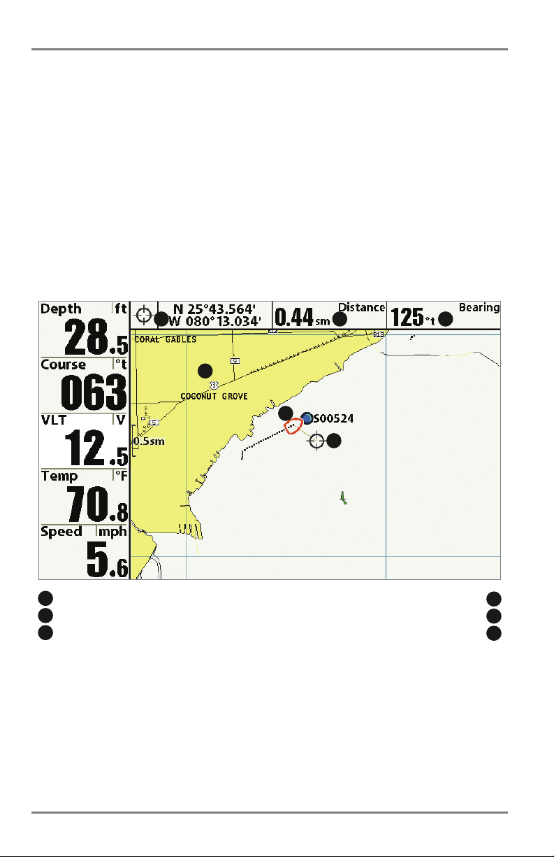
Chart View
Chart View shows cartography from the built-in UniMap or an optional microSD card map for the
area surrounding your current position. The cartography is applied to any standard Chart View or
Combo view that displays a chart. The current track (also known as the position history or
breadcrumb trail) showing where the boat has been, along with saved tracks, waypoints, and the
current route (when navigating), are overlaid on the chart.
NOTE: See Introduction to Navigation for more information.
• Shift/Pan: Use the 4-WAY Cursor Control key to shift/pan the chart to another area.
• Zoom: Press the ZOOM (+/-) keys to zoom in and out.
• Information: Press the CHECK/INFO key to get information about the chart objects near
the cursor.
Chart View with Cursor (Standard)
1 2 3
6
5
4
1
Latitude and Longitude Position of Cursor
2
Distance to the Cursor
3
Bearing to the Cursor
Chart Views
50
Cursor
Boat Icon
Cartography
4
5
6
Page 57

Chart No Readouts View (HELIX GPS only)
If you have a HELIX GPS, you can display the Chart View without digital readouts. Chart No
Readouts View has the same cartography capabilities as the standard Chart View.
Chart No Readouts View
6
5
1
2
4
3
1
Map Scale
2
Cartography
3
Waypoint Icon with Saved Screen Snapshot
51
Boat Icon
Course Projection Line
Route
Chart Views
4
5
6
Page 58

Chart Big Digits View (HELIX GPS only)
Chart Big Digits View has the same cartography capabilities as the standard Chart View, and
it includes multiple digital readouts. Navigation digital readout windows are always displayed
on-screen, even when the control head is not navigating.
Chart Big Digits View
6
5
1
1
Digital Readouts
2
Track
3
Waypoint
4
3
2
Boat Icon
4
Course Projection Line
Route
5
6
Chart Views
52
Page 59
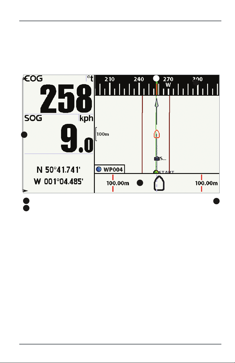
Chart Instrument View (HELIX GPS only)
Chart Instrument View displays a digital compass, XTE (Cross Track Error) graphic, and large
digital readouts in one view.
Change Digital Readouts: Press the MENU key once. Choose Select Readouts, and press the
RIGHT Cursor key to change the digital readouts displayed on this view.
Chart Instrument View
1
1
Large Digital Readouts
2
Digital Compass
2
3
3
XTE Graphic
3
53
Chart Views
Page 60

Chart View Orientation
Both Chart and Chart Combo Views allow you to choose the orientation of the view (see
Navigation Menu Tab: Chart Orientation). In each orientation, the view pans automatically so that
the boat is always centered on the display. To see more of the view when the boat is traveling at
the speed you set, see Chart Menu Tab: Vessel Offset and Offset Speed.
• North-Up: True North is shown at the top of the display. Objects located to the north of
the boat are drawn above the boat.
• Head-Up: The boat’s current heading points up, and the chart rotates around the vessel
so that the vessel always points up on the view.
• Course-Up: During navigation, the projected course is shown at the top of the view.
Objects ahead of the boat are drawn above the boat. When the boat is not navigating, the
course-up reference is provided by the COG (course over ground) calculation. Also, to
display the north icon on the view, see Navigation Menu Tab: North-Up Indicator.
North-Up Icon: If it is turned on, the North-Up Icon displays the direction of True North. It also
displays the Chart Orientation, and the icon will change as the orientation and the data source
change (see Navigation Menu Tab: North-Up Indicator).
When the boat is stationary, it is drawn as a circle.
When the boat is in motion, it takes on a boat shape, pointed in the direction
of motion (always up in the Course-Up orientation).
Chart Orientation
54
Page 61

Viewing Cartography
In the Chart and Chart Combo Views, there are several cartography-related functions that you
can access using various keys.
Panning: Use the 4-WAY Cursor Control key to move the chart around on the display in the
direction of the key being pressed. When you do this, a bull’s eye cursor is drawn at the center
of the screen and is linked to the boat by a yellow line, even if the boat is off the screen. At the
same time, a cursor dialog box is displayed with the distance and bearing from the boat to the
cursor position and the latitude/longitude coordinates of the cursor. When the cursor is active on
the display, you can also use the 4-WAY Cursor Control key to move the cursor diagonally.
Chart View with Cursor Present
Zooming: Press the Plus (+) key to Zoom In and the Minus (-) key to Zoom Out to see the
cartography at different magnification levels. The zoom level is indicated on the left side of the
display. If you zoom in beyond the available chart data, the display will go into Overzoom mode
whereby the last available chart data is amplified to reflect the level selected. If you zoom in so
far that no cartography is available, a lat/long grid will be drawn instead. Zooming is also
influenced by the Auto Zoom and Auto Range settings. See Chart Menu T ab: Auto Zoom and Auto
Range for more information.
Decluttered Waypoints: When two or more waypoints overlap, or are displayed close together
on a chart view, the screen will automatically declutter — waypoint names will shorten and the
waypoint icons will change into small blue icons.
To view a Decluttered Waypoint at full size, use the 4-WAY Cursor Control key to move the cursor
onto a decluttered waypoint icon. When the cursor snaps onto the icon, the full-size waypoint
name and icon will be displayed. You can also press the + ZOOM key until you can see the
individual waypoints on the screen.
55
Viewing Cartography
Page 62
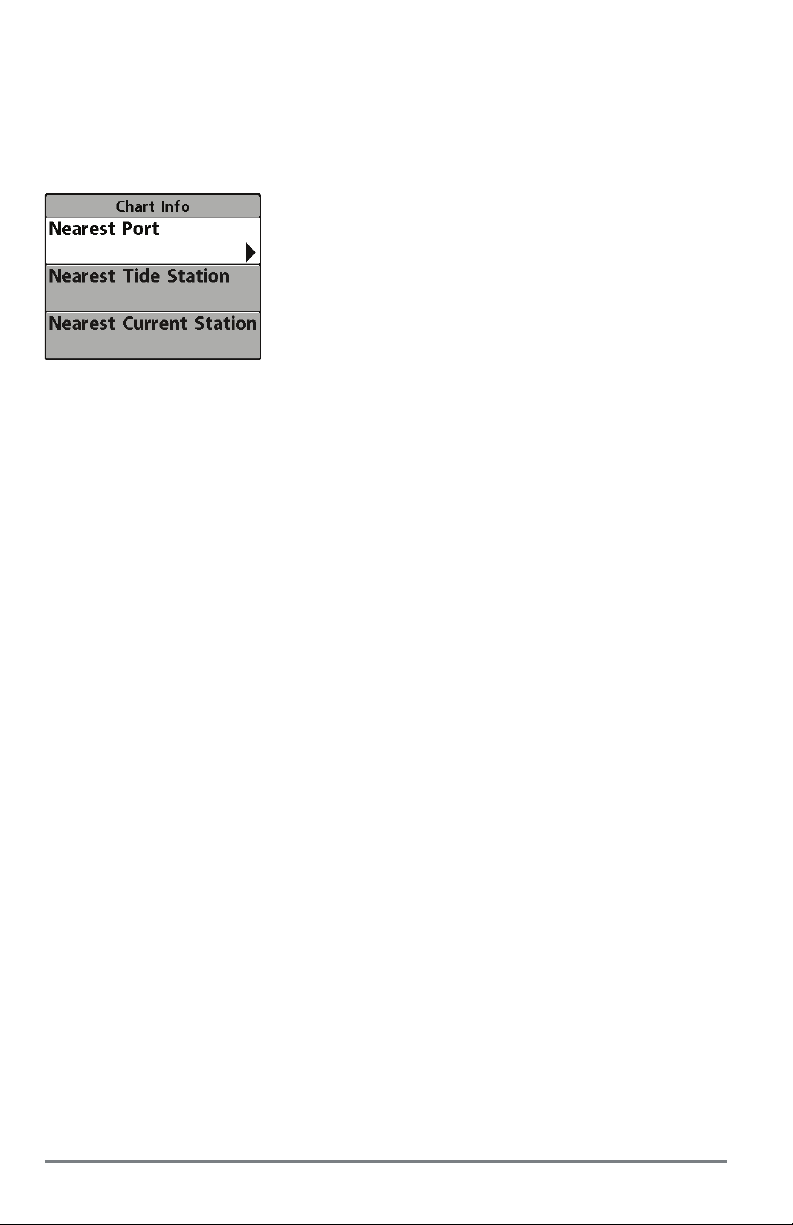
Screen Snapshots and Recording Icons: When a waypoint is created while Screen Snapshot and
Recording is active, the waypoint will appear as a snapshot icon or recording icon in chart views.
See Views: Snapshot and Recording View for more information.
Chart Info: Press the CHECK/INFO key to get detailed information about the chart. If the cursor
is active, you will see information about the chart objects located near the cursor.
If the cursor is not active, the Chart Info submenu will appear.
Use the 4-WAY Cursor Control key to select the Nearest Port, the
Nearest Tide Station, or the Nearest Current Station and see
information about any of these objects.
NOTE: The built-in UniMap does not contain any Port, Tide, or Current
information. This information is only available from an optionalpurchase microSD card.
Nearest Port: The position and services information for the nearest port to your present position
will be displayed. Press the EXIT key to remove the information box and the cursor bull’s eye will
be centered over the port position. The cursor information boxes will indicate the distance and
bearing to the port from your present position.
Nearest Tide Station: Tide information for the nearest tide station to your present position will
be displayed. This includes the position of the station and the times of the high and low tides for
today’s date. A tide graph is also displayed showing the rise and fall of the tides for the 24 hour
time period encompassing the date. You can change the date to look at tide information before
or after the date displayed by pressing the LEFT or RIGHT Cursor key respectively. Press the EXIT
key to remove the information box, and the cursor bull’s eye will be centered over the tide station
position. The cursor information boxes indicate the distance and bearing to the tide station from
your present position.
Nearest Current Station: Current information for the nearest current station to your present
position will be displayed. This includes the position of the station and the current changes for
today . Two graphs are also presented that show the time, direction, and flow speed of the current
changes for the 24 hour time period of today’s date. You can change the date to look at current
information before or after the date displayed by pressing the LEFT or RIGHT Cursor key
respectively. Press the EXIT key to remove the information box, and the cursor bull’s eye will be
centered over the current station position. The cursor information boxes will indicate the distance
and bearing to the current station from your present position.
Viewing Cartography
56
Page 63

Introduction to Navigation
Your control head allows you to mark waypoints and start navigation with the control head keys
or the Navigation X-Press Menu.
You can also use the Waypoint Management dialog box to create new waypoints and routes from
scratch. You can edit your navigation data and organize it too. This section will get you started.
See your Humminbird Waypoint Management Guide for complete details.
Waypoints, Routes, and Tracks
Waypoints, Routes, and Tracks
1
2
8
3
4
11
10
9
5
6
7
1
Depth
2
Course: Direction the boat is traveling relative to North Reference
3
Bearing: Direction to Destination Waypoint Relative to North Reference
4
XTE: Cross Track Error. Distance of Boat from Route
5
DTG: Distance to Go to Waypoint
TTG: Estimate of Trip Time to Destination Waypoint
Speed Over Ground: Speed of Boat
Off-Course Alarm Limits
Map Scale
Waypoint
Route
6
7
8
9
10
11
Waypoints are stored positions that allow you to mark areas of interest or navigation points. Your
control head can store up to 2500 waypoints.
Routes link two or more waypoints together to create a path for navigation, and are used in trip
planning. You can link individual waypoints together by using the GOTO key . Your control head can
store up to 47 routes that can each contain up to 50 waypoints.
A route represents your intended navigation and shows the shortest path from each waypoint to
the next. As you travel a route, staying on the route line is the most efficient way to get to your
57
Introduction to Navigation
Page 64

destination, although you should always look out for obstacles not shown on the chart. A Route
Leg is the path between each waypoint in a route. The color of each route leg is displayed as
follows:
• Completed Route Leg = Gray
• Current Route Leg = Green
• Future Route Leg = Gold
Tra cks consist of detailed position history, and are displayed as a breadcrumb trail of trackpoints.
The Current Track shows the position history since the unit was powered up. You can clear the
Current Track or save it at any time. Your control head can store up to 50 saved tracks, each
containing 20,000 trackpoints. The current track represents your actual path so far.
NOTE: The maximum number of waypoints and routes may vary due to the setup of your Waypoint
Management directory. Groups and sub-groups also use storage, and the storage limit is
influenced by the complexity of your Waypoint Management directory. See your Waypoint
Management Guide for details.
Introduction to Navigation
58
Page 65

Opening the Waypoint
Management Dialog Box
Open the Waypoint Management Dialog Box
The Waypoint Management dialog box allows you to
organize your waypoints, routes, and tracks on your
Humminbird control head.
Open the Waypoint Management Dialog Box
1. Press the MENU key twice to open the Main Menu.
2. Press the RIGHT Cursor key until the Navigation
Menu Tab is selected.
3. Press the DOWN Cursor key to choose Waypoints,
Routes, Tracks. Press the RIGHT Cursor key to open
the Waypoint Management dialog box.
59
Introduction to Navigation
Page 66
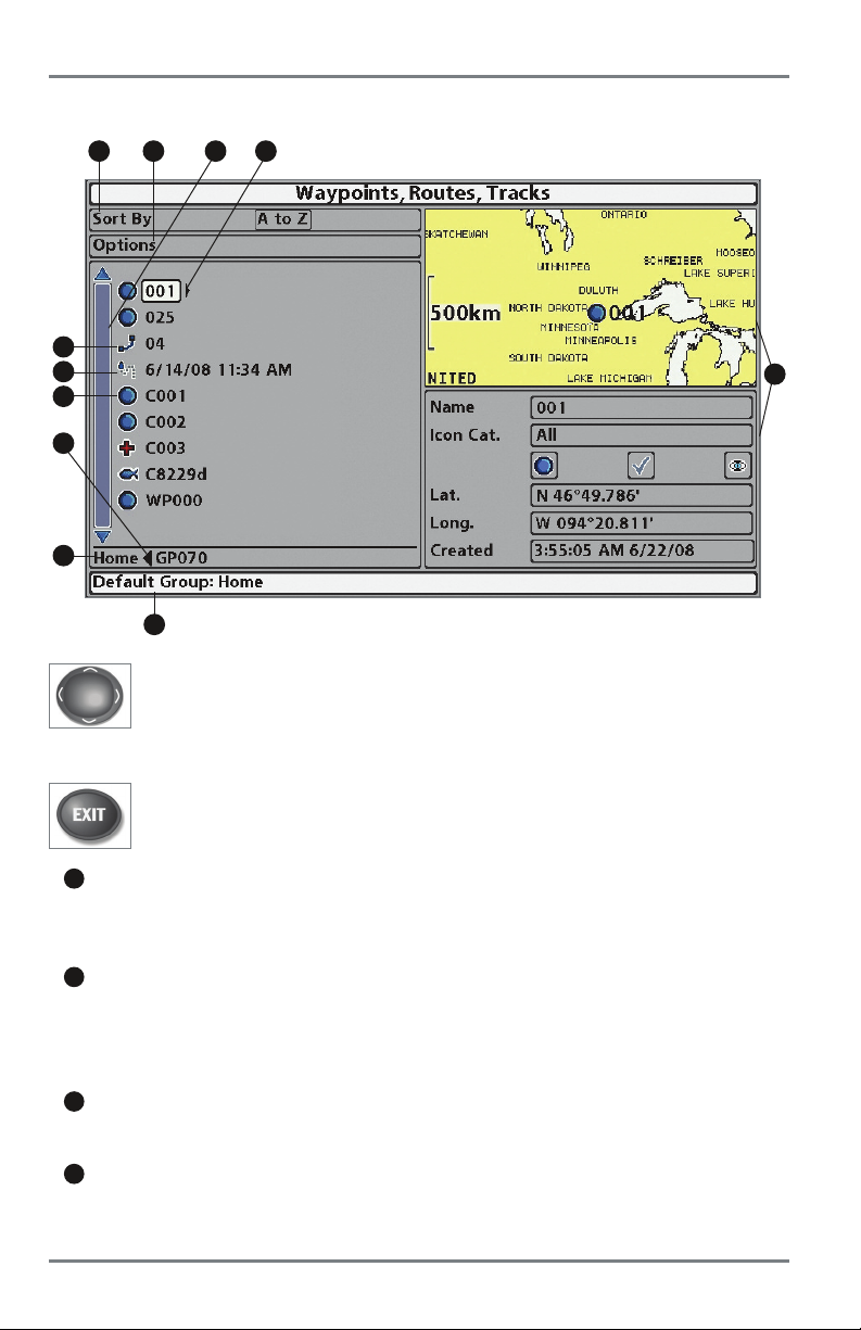
What’s on the Waypoint Management Dialog Box
Use the Waypoint Management dialog box to manage your waypoints, routes, and tracks.
K
J
I
H
G
A B
C D
F
Use the 4-WAY Cursor Control key to select a waypoint, route, track, group, or menu
option. To scroll through the list, press the UP or DOWN Cursor keys. To open a
submenu, press the RIGHT Cursor key. To move to the higher level group, or the
higher level directory, press the LEFT Cursor key.
E
As you scroll through the Waypoint Management dialog box, press the EXIT key to
select the Options menu quickly. Press the EXIT key twice to close the dialog box.
A
Sort By: Select Sort By, and press the RIGHT Cursor key repeatedly to choose a sorting
option for the waypoints, routes, tracks, and groups (A - Z, Z - A, Newest, Oldest,
Distance, Icon). To start a more specific search, see Options.
B
Options: Provides a submenu so that you can set the default group, create new
navigation items (groups, waypoints, routes), and select and edit several items at once.
Select Search By to search by Name, Distance, Date, Icon, or Icon Category. The Options
menu will also change to show related menus such as Save or Paste.
C
Scroll and View: Press the UP or DOWN Cursor keys to browse through the full list of
saved waypoints, routes, tracks, and groups. The selected item is highlighted in white.
D
Submenu: After an item is selected, press the RIGHT Cursor key to view the submenu.
Introduction to Navigation
60
Page 67

E
Preview Window: As you scroll, the selected item’s information is displayed on the right
side of the Waypoint Management dialog box. Press the +/– ZOOM keys to view the
position closer or farther away in the preview window.
F
Information: Displays the default group where all new waypoints, routes, and tracks will
be saved. In this illustration, Home is the default group. This field also changes to display
instructions.
G
Directory: Shows the directory structure and the currently selected group. The illustration
shows group GP070 as the selected group.
H
Arrows: When arrows are displayed on a menu option, additional information or
submenus are available. If the arrow points to the right, press the RIGHT Cursor key. If
the arrow points to the left, press the LEFT Cursor key to move up to the higher level
group directory.
I
Waypoint Icon: The blue circle icon is the default waypoint icon. Waypoint names are
alphanumeric and begin with WP. You can also change the icon, waypoint name, add it
to a route, and more. If the waypoint is saved with a snapshot or recording file, see the
Snapshot and Recording View on your control head to view the snapshot or recording.
J
Track Icon: Track names are saved with a date and time stamp, and certain track
information can be edited (see Edit your Waypoints, Routes, Tracks, and Groups).
K
Route Icon: Route names are alphanumeric and begin with R. To change the Route name
and its waypoints, see Edit your Waypoints, Routes, Tracks, and Groups.
61
Introduction to Navigation
Page 68

Save, Edit, or Delete a Waypoint
Save your Current Position as a Waypoint: On any view, press the MARK key to save the current
position of the boat as a waypoint.
Save the Cursor Position as a Waypoint: On the Chart or Chart Combo Views, use the 4-WAY
Cursor Control key to move the cursor to the position you want to save as a waypoint. Then press
the MARK key to save the position as a waypoint.
Save a Position from the Sonar History: On any Sonar View or Down Imaging View, use the
4-WAY Cursor Control key to move the cursor to a feature in the sonar history. Press the MARK
key to create a waypoint at the location where that sonar reading was taken. The new waypoint
will also record the depth at that location.
NOTE: When you save a waypoint by any of these methods, a numerical waypoint name is
automatically assigned. You can edit the waypoint information later to give it a different name and
select an icon to represent it (see Edit your Waypoints, Routes, Tracks, and Groups).
Create a New Waypoint: To create a waypoint that is NOT your current position, open the
Waypoint Management dialog box. Select Options > New > New Waypoint. Use the 4-WAY
Cursor Control key to set the available fields. See Edit your Waypoints, Routes, Tracks, and
Groups for details.
Delete a Waypoint: Open the Waypoint Management dialog box. Select a Waypoint, and press
the RIGHT Cursor key to open the Waypoint submenu. Select Delete, and press the RIGHT Cursor
key. To remove the Waypoint from the group, choose Selected. To delete the waypoint from all
groups, choose All Instances.
Navigate to a Waypoint or Position
Navigate to the Cursor Position: From the Chart View or Chart Combo Views, use the 4-WAY
Cursor Control key to move the cursor to a position or waypoint on the display. Press the GOTO
key.
Navigate to a Selected Waypoint: Press the GOTO key. Press the DOWN Cursor key to highlight
a waypoint from the saved waypoints list, and press the RIGHT Cursor key to start navigation.
NOTE: By repeating the previous instructions, you can add morewaypoints to create a longer multi-segment
route.
Navigate to a Waypoint from the Waypoint Management Dialog Box: Open the Waypoint
Management dialog box. Select a Waypoint, and press the RIGHT Cursor key to open the
Waypoint submenu. Select Go To, and press the RIGHT Cursor key.
Skip a Waypoint: From the Navigation X-Press Menu, select Skip Next Waypoint, and press the
RIGHT Cursor key. If there is not another waypoint to skip to, navigation will be cancelled.
Introduction to Navigation
62
Page 69

Cancel Navigation: From the Navigation X-Press Menu, select Cancel Navigation, and press the
RIGHT Cursor key. Canceling navigation removes the route and any waypoints created using the
GOTO key, but it does not remove any saved routes from memory. You will be prompted to save
the current route when you cancel navigation.
Add a Waypoint Target or Trolling Grid
The Waypoint Target shows a target consisting of concentric circles in various distance ranges
centered on the waypoint you choose. The Trolling Grid shows various distance ranges in grid
format from the waypoint you choose. The trolling grid can be used as a guide when trolling around
a waypoint.
Add a Waypoint Target: Open the Waypoint Management dialog box and select a Waypoint.
Press the RIGHT Cursor key, and select Target. Press the RIGHT Cursor key.
Add a Trolling Grid: Open the Waypoint Management dialog box and select a Waypoint. Press
the RIGHT Cursor key, and select Grid. Press the RIGHT Cursor key. The grid can also be rotated
to any heading by adjusting the Grid Rotation setting on the Navigation Main Menu.
Remove a Target or Trolling Grid: Press the MENU key once, and choose Remove Target or
Remove Grid from the Navigation X-Press Menu, and press the RIGHT Cursor key.
NOTE: Only one waypoint can have either a target or a grid applied to it at one time. If you apply a
target or a grid to a new waypoint, the original waypoint will lose its target or grid.
NOTE: The spacing of the rings on the waypoint target and the spacing of the grid lines on the trolling
grid are the same as the length of the scale bar on the left edge of the display. Zooming in or out will
decrease or increase the spacing, respectively.
Chart View with Target Chart View with Grid
1
Map Scale
2
Waypoint Target
1
2 2
1
2
63
1
Map Scale
Waypoint Trolling Grid
Introduction to Navigation
Page 70

Routes
Save the Current Route: While you are navigating, the current route can be saved. From the
Navigation X-Press Menu, select Save Current Route, and press the RIGHT Cursor key. Navigation
will continue.
Create a New Route: Open the Waypoint Management dialog box. Select Options > New > New
Route.
• New Route Dialog Box: Use the 4-WAY Cursor Control key to set the available fields (see
Edit your Waypoints, Routes, Tracks, and Groups for details).
• Plan a Route: Select Plan Route, and press the RIGHT Cursor key. The New Route dialog
box closes so that you can select waypoints from the Waypoint Management dialog box.
To add a selected waypoint to the route, press the RIGHT Cursor key. Repeat as needed.
Select Save and press the RIGHT Cursor key.
Adding Waypoints to a Route
A
B
D
C
Save: Press the EXIT key to choose Save.
A
Press the RIGHT Cursor key to confirm the save.
B
Selected Waypoint: Press the RIGHT Cursor
key to add it to the Route.
New Route Information: Shows
the Route’s name and next steps.
A confirmation displays each time
you add a waypoint to the Route.
C
D
Travel a Saved Route: Open the Waypoint Management dialog box. Select a saved route, and
press the RIGHT Cursor key. Select Travel, and press the RIGHT Cursor key. Select Forward to
travel the route in order. Select Reverse to travel the route in reverse order.
Edit the Waypoint Order in a Route: Open the Waypoint Management dialog box. Select a
Route, and press the RIGHT Cursor key to open the Route submenu. Select Open, and then choose
one of the following options:
• Select Reverse, and press the RIGHT Cursor key. This will quickly reverse the order of the
route. Press the EXIT key to select Save. Press the RIGHT Cursorkey to confirm your changes.
Introduction to Navigation
64
Page 71
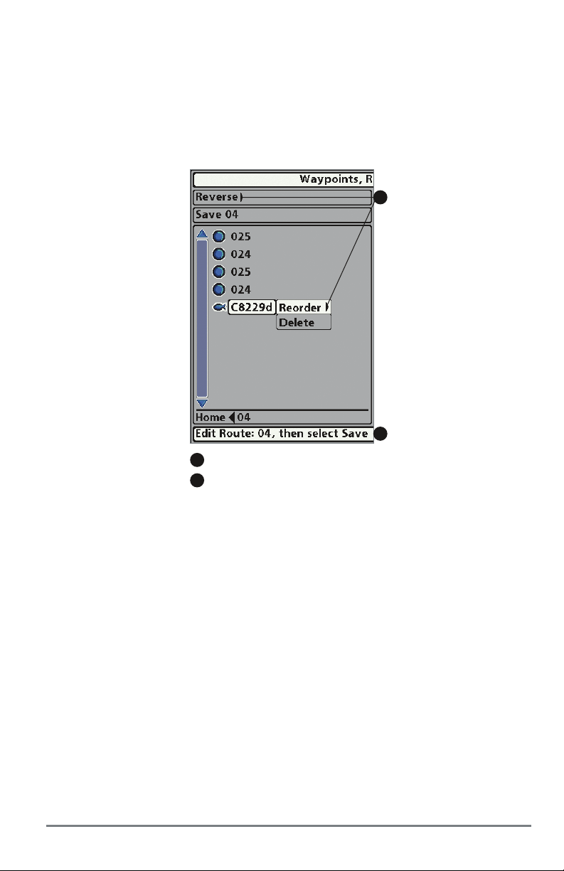
OR
• Choose a Waypoint in a Route, and press the RIGHT Cursor key. Select Reorder, and
press the RIGHT Cursor key. To move the waypoint up or down in the route order, press
the UP or DOWN Cursor keys.
Press the EXIT key to select Save. Press the RIGHT Cursor key to confirm your changes.
Changing the Waypoint Order
in a Route (two options)
A
B
Select Reverse OR Select a Waypoint > Reorder
A
B
Press the EXIT key to select Save.
Review Route Info: Open the Waypoint Management dialog box. Select a saved route, and press
the RIGHT Cursor key. Select info, and press the RIGHT Cursor key. The Route Info dialog box
displays the waypoints in the route. The distance and bearing from each waypoint to the next,
as well as the distance and bearing from the current position to the first waypoint in the route
will be displayed.
Delete a Saved Route: Open the Waypoint Management dialog box. Select a saved route, and
press the RIGHT Cursor key. Select Delete from the submenu, and press the RIGHT Cursor key. To
remove the route from the group, choose Selected. To delete the route from all groups, choose
All Instances.
65
Introduction to Navigation
Page 72

Tracks
Save the Current Track: From the Navigation X-Press Menu, select Save Current Track, and press
the RIGHT Cursor key. The track will remain on the display but will change from black to gray. To
remove the track completely from the display, see Hide or Display a Saved Track and Stop
Tr acking.
NOTE: When you save a track, a name is automatically assigned. The track name consists of a date/time
stamp, but can be re-named later (see Edit your Waypoints, Routes, Tracks, and Groups).
Clear the Current Tr ack: From the Navigation X-Press Menu, select Clear Current Track, and press
the RIGHT Cursor key. The track will be removed from the display and permanently deleted.
Hide or Display a Saved Track: Open the Waypoint Management dialog box. Select a saved
track, and press the RIGHT Cursor key. Select Edit from the submenu. Use the 4-WAY Cursor
Control key to set the track to visible or hidden (see Edit your Waypoints, Routes, Tracks, and
Groups for details).
Delete a Saved Track: Open the Waypoint Management dialog box. Select a saved track, and
press the RIGHT Cursor key. Select Delete from the submenu, and press the RIGHT Cursor key. To
remove the track from the group, choose Selected. To remove the track from all groups, choose
All Instances.
Stop Tracking: Press the MENU key twice to open the Main Menu. Select the Navigation Menu
Tab > Current Track > Stop Tracking. Stop Tracking clears the current track, and the unit will not
save trackpoints. See Navigation Menu Tab: Current Track for more information.
Edit your Waypoints, Routes, Tracks, and Groups
Whether you are creating a new navigation item or
editing it, you can use the same steps to customize a
waypoint, route, track, or group. The available settings
will depend on the type of item you are editing.
NOTE: The Edit Way point dialog box is also av ailable when
you select a waypoint from the Navigation X-Press Menu.
NOTE: See your Humminbird Waypoint Management Guide
for more information about groups and the other great
features of the W a ypoint Management dialog box.
Visible on Chart View
Hidden on Chart View
Introduction to Navigation
66
Page 73

Edit a Waypoint, Route, Track, or Group
1. Open the Waypoint Management dialog box.
2. Open the Submenu: Use the 4-WAY Cursor Control key to select a waypoint, route,
track, or group. Press the RIGHT Cursor key to open the submenu.
3. Select Edit, and press the RIGHT Cursor key.
4. Select a Field: Use the 4-Way Cursor Control key to move from field to field, and press
the UP or DOWN Cursor keys to change the settings.
Name: Press the RIGHT or LEFT Cursor keys to move from space to space, and press
the UP or DOWN Cursor keys to set the letter or number. All upper and lower case
letters are available, as well as digits 0-9 and some punctuation symbols.
Icon Category: Press the UP or DOWN Cursor keys to scroll through the available
categories. Select All to view all available icons. (All, Geometry, Alerts, Supplies,
Navigation, Recreation, Fish, Environment)
Icon: Press the UP or DOWN Cursor keys to scroll through the available icons used
to represent the waypoint in Chart View. The available icons are determined by the
category selected in Icon Category.
Visible: Press the UP or DOWN Cursor keys to set the selected item to visible or
hidden in the Chart View.
Latitude/Longitude: Press the RIGHT or LEFT Cursor keys to move from space to
space, and press the UP or DOWN Cursor keys to set the letter or number.
NOTE: The available settings will depend on the type of item you are editing.
5. Select Save, and press the RIGHT Cursor key to confirm your changes.
67
Introduction to Navigation
Page 74

Man Overboard (MOB) Navigation
As soon as you know that you have a man overboard (MOB), you should activate MOB
navigation to maximize the chances for a successful rescue. MOB navigation allows you to create
an MOB waypoint to locate the point at which your man went overboard and the relation of the
boat to that point.
Activate MOB navigation: Press and hold the GOTO key for more than 1.5 seconds to activate
the Man Overboard (MOB) function.
When MOB is activated, a MOB waypoint is created at the boat's current position, regardless of
whether the chart cursor is active or not. The MOB waypoint has a large, distinctive icon. Once
MOB is activated, any current navigation will be cancelled and the current route will be discarded
without user notification. MOB navigation will begin immediately, and the MOB View will show
the following:
• The view will switch to the Chart View, and the elapsed time since MOB was activated
will be displayed.
• A line will be drawn from the boat's current position to the MOB waypoint, and the MOB
waypoint will be targeted.
• The latitude/longitude position of the MOB waypoint will be displayed in an additional
information box.
Cancel MOB Navigation: From the Navigation X-Press Menu, select Cancel MOB, and press the
RIGHT Cursor key. Canceling MOB navigation removes the route and any waypoints created using
the GOTO key but does not remove any saved routes from memory.
Man Overboard (MOB) Navigation
68
Page 75

MOB Navigation
4
3
5
1
Position where man fell overboard
2
Elapsed time since MOB was activated
3
Boat icon
1
Target surrounding MOB waypoint
2
MOB waypoint
It is not possible to re-activate MOB or modify the current route without first canceling MOB
navigation. The Off Course trigger is also disabled and the Off Course Alarm circle is not drawn.
Any press of the GOTO key, or selection of a GOTO menu option, will cause an error beep and
a short message will be displayed that will disappear after 2 seconds.
4
5
69
Man Overboard (MOB) Navigation
Page 76

The Menu System
The Menu System is divided into easy-to-use menu modules as follows:
• Start-Up Options Menu: Press the MENU key during the power on sequence to view the
Start-Up Options Menu. From the Start-Up Options Menu, you can choose the following
modes: Normal, Simulator, and System Status.
• X-Press Menu: The X-Press Menu provides a shortcut to the most frequently-used
settings, and the options on the X-Press Menu correspond with the current view.
• Main Menu: The Main Menu is a standard set of menu settings which are organized
under the following tabbed headings: Alarms, Sonar, Navigation, Chart, Setup, and Views.
The available menu tabs are determined by your control head model.
NOTE: The X-Press Menu(s) and the Main Menu options can also be expanded or simplified by setting
the User Mode to Advanced or Normal (see Main Menu: User Mode).
The Menu System
70
Page 77

Start-Up Options Menu
Press the MENU key during the power on sequence to view the Start-Up Options Menu, and
select one of the modes described on the following pages. Also, see Power On for more
information.
Start-Up Options Menu
Normal
Use Normal for on-the-water operation. If your model includes sonar, a transducer must be
connected to the control head to use Normal mode.
To exit Normal operation, power off your control head.
71
Start-Up Options Menu
Page 78

Simulator
Use Simulator to learn how to use your control head before taking your boat on the water. The
Simulator is a very powerful tool that provides a randomly-updated display which simulates on
the water operation.
Simulator
We recommend going through this manual while using the Simulator, since all of the menus
function and affect the display in the same way as they would in Normal operation. Any menu
changes you make will be saved for later use.
•Amessage will appear often on the display to indicate Simulator mode.
• To exit Simulator, power off your control head.
NOTE: It is important to select Simulator manually from the Start-Up Options Menu instead of letting the
control head enter Simulator automatically. See Power On for more information.
Start-Up Options Menu
72
Page 79

System Status
Use System Status to view system connections and to conduct a unit self-test.
After you select System Status from the Start-Up Options Menu, press the VIEW key to display
the following options:
•SelfTest
• Accessory Test
• GPS Diagnostic View
To exit System Status, power off your control head.
Self Test displays results from the internal diagnostic self test, including unit serial number,
Printed Circuit Board (PCB) serial number, software version, total hours of operation, and the
input voltage.
Self Test Screen
Accessory Test lists the accessories connected to the system.
Accessory Test Screen
NOTE: The speed accessory will be detected only if the paddlewheel has moved since your control head
was powered up.
73
Start-Up Options Menu
Page 80

GPS Diagnostic View shows a sky chart and numerical data from the GPS receiver. The sky chart
shows the location of each visible GPS satellite with its satellite number and a signal strength bar.
A dark gray bar indicates that the satellite is being used to determine your current position. A light
gray bar indicates that the satellite is being monitored, but is not yet being used.
This view also reports the current position, local time and date, and other numeric information.
The current GPS Fix Type is reported as No Fix, 2D Fix, 3D Fix, or Enhanced. An Enhanced fix has
been augmented using information from WAAS, EGNOS, or MSAS. A 3D or Enhanced Fix is
required for navigation. HDOP (the Horizontal Dilution of Precision) is a GPS system parameter
which depends on the current satellite configuration. HDOP is used to calculate the Estimated
Position Error.
GPS Diagnostic View
1
Sky Chart
2
Satellite Being Used
1
4
3
2
Current Latitude and Longitude
Satellite Being Monitored
3
4
Start-Up Options Menu
74
Page 81
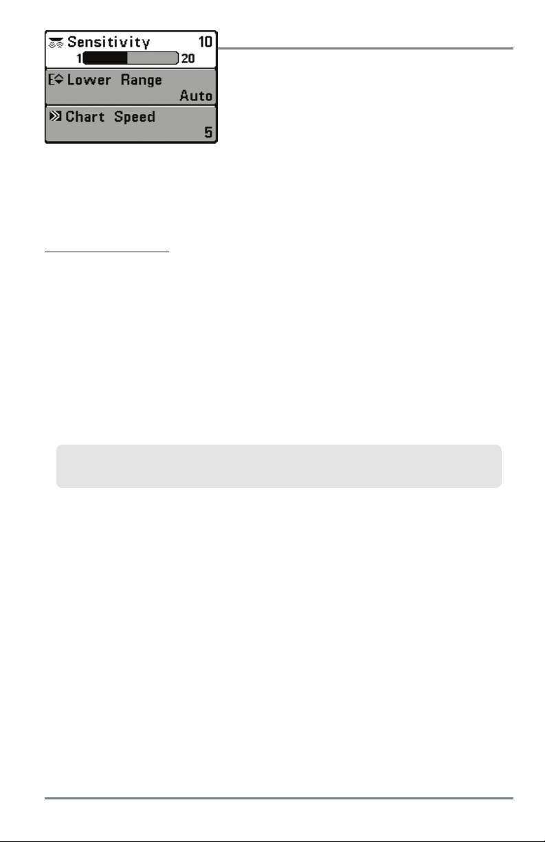
X-Press Menu
The X-Press Menu provides a shortcut to your most
frequently-used settings. The options provided on the
X-Press Menu correspond with the current view. For
example, if you are in a Sonar View and press the MENU
key once, the Sonar X-Press Menu will display.
X-Press Menu
To use an X-Press Menu:
1. In any view, press the MENU key once.
2. Press the UP or DOWN Cursor keys to highlight an X-Press Menu option, then use the
RIGHT or LEFT Cursor keys to change the menu setting.
NOTE: The X-Press Menu will collapse temporarily and the screen will update if it is affected by your
menu setting change, which allows you to see the effects of your change immediately.
3. Reactivate the X-Press Menu by pressing the UP or DOWN Cursor keys.
Total Screen Update - When you change any menu settings that affect the current view, the
view will update immediately (you don’t have to exit the menu to apply the change to the screen).
Menu options can be simplified or expanded by setting the User Mode to Normal or Advanced.
See Main Menu: User Mode for details.
75
X-Press Menu
Page 82

Main Menu
The Main Menu provides the standard set of menu options,
including the settings that are changed less frequently.
NOTE: Menu options can be expanded or simplified by setting
the User Mode to Advanced or Normal. See Main Menu: User
Mode for details.
MainMenuSystem
Normal User Mode
To use the Main Menu:
1. In any view , press the MENU key twice.
2. Press the RIGHT or LEFT Cursor keys to highlight a menu tab.
3. Press the DOWN or UP Cursor keys to select a specific menu option under that tab.
4. Press the RIGHT or LEFT Cursor keys again to change a menu setting.
• A down arrow at the bottom of a menu means that you can scroll to additional menu
options using the DOWN Cursor key.
• A right or left arrow on a menu option means that you can use the RIGHT or LEFT
Cursor keys to make changes or to see more information.
• Press the EXIT key to move quickly to the top of the tab.
Total Screen Update - When you change any menu settings that affect the current view, the
view will update immediately (you don’t have to exit the menu to apply the change to the
screen).
Main Menu
76
Page 83

Quick Tips for the Main Menu
• From any menu option on a menu tab, press the EXIT key to jump directly to the top of
the tab.
• From the bottom of a menu tab, press the DOWN Cursor key to jump directly to the top
of the tab.
• From the top of a menu tab, press the LEFT or RIGHT Cursor keys to scroll to the next tab.
You can also jump to the beginning or end of the tab rotation by repeatedly pressing the
RIGHT or LEFT Cursor keys.
• If there is a down arrow at the bottom of a menu tab, press the DOWN Cursor key to
scroll to additional menu options.
• If there is a right or left arrow on a menu option, press the RIGHT or LEFT Cursor keys
to make setting changes or see more information.
• If you press MENU or EXIT to leave the Main Menu and then return to the Main Menu
at a later time, the menu will open to the same tab as the last time the Main Menu was
displayed.
Note for all Menu Settings
The settings in all menus are adjusted in the same way. Simply use the 4-WAY Cursor Control key
to highlight a menu option, and then change the settings or activate the option (see Main Menu
or X-Press Menu).
Below is an example of how the menu options are described in this manual. Each description
shows the menu option appearance, the available settings, and the specific control head settings
required (advanced user mode, international only, view, navigation, or accessory).
Menu Option Name
Noise Filter
(Advanced)
Settings: Off, Low, Medium, High1, High2, High3,
Default = Low
Noise Filter adjusts the sonar Noise Filter to limit interference on the display
from sources such as your boat engine, turbulence, or other sonar devices.
Menu Option as it appears on the screen
77
Setup User Mode and other
control head requirements
Available Menu Settings and Default
Setting Description
Menu Quick Tips
Page 84

User Mode (Normal or Advanced)
Menu options can be simplified or expanded by setting your control head User Mode to Normal
or Advanced.
Normal Mode is provided for users who want greater simplicity and fewer menu choices.
Advanced Mode is provided for users who want the highest level of control over the control
head. Several menu settings are added to the Main Menu when the User Mode is changed to
Advanced.
To change the User Mode setting
:
1. Press the MENU key twice to access the Main Menu.
2. Press the RIGHT Cursor key until the Setup tab is selected.
3. Press the DOWN Cursor key to highlight User Mode on the Setup main menu.
4. Press the LEFT or RIGHT Cursor keys to change the User Mode setting. (Normal,
Advanced, Default = Normal)
NOTE: Any changes made while in Advanced Mode will remain in effect after you switch back to
Normal Mode.
For example, in HELIX SONAR GPS models, the Select Readouts menu option is available when the
User Mode is set to Advanced.If you change the Select Readouts settings while operating in Advanced
User mode, the Select Readouts you choose will continue to display on the screen even if you switch
back to Normal User Mode.
Main Menu
78
Page 85

HELIX DI GPS
Sonar Tab, Normal Mode
HELIXDIGPS
Sonar Tab, Advanced Mode
79
Main Menu
Page 86

Sonar X-Press Menu
Sonar X-Press Menu
(HELIX SONAR GPS, HELIX DI GPS, HELIX XD GPS only)
The Sonar X-Press Menu provides a shortcut to your most
frequently-used settings. Press the MENU key once while
in any of the Sonar Views to access the Sonar
X-Press Menu.
NOTE: Menu options can be expanded or simplified by setting
the User Mode to Advanced or Normal. See Main Menu: User
Mode for details.
NOTE: Menu options are determined by your Humminbird model.
See the following pages for full menu descriptions.
Sonar X-Press Menu
80
Page 87

Cancel Navigation
(only when Navigating)
Settings: Press the RIGHT Cursor key and follow screen instructions.
Cancel Navigation discards the current route and exits Navigation Mode. T his menu option will only
appear when you are currently navigating a route. This will not delete a previously-saved route.
Active Side
(Combo Views only)
Settings: Left, Right; Default = Left
Active Side allows you to select a side of the screen in a Combo View. After you choose an active
side, you can apply menu settings and key commands to the view you’ve selected. The Active Side
menu option is only available when a Combo View is on the screen (see Views: Combo Views).
• A green arrow on the Combo View points to the active side.
• When a menu is displayed in the active side, the non-active side of the screen will be
grayed out.
Split Position
(Combo Views only)
Settings: Left, 30, 40, 50, 60, 70, Right; Default = Various
Split Position sets the size of the left side of the Combo View. Each Combo View can be set
individually. The Split Position menu option is only available when a Combo View is on the screen
(see Views: Combo Views).
• The number setting indicates the percentage taken up by the left side of the Combo View.
• Selecting Left sets the left side of the screen to its smallest setting.
81
Sonar X-Press Menu
Page 88

Sensitivity
Settings: Low = 1, High = 20; Default = 10
Sensitivity controls how much detail is shown on the display and will adjust the sensitivity of all
sonar frequencies.
Decrease the sensitivity to eliminate the clutter from the display that is sometimes present in
murky or muddy water. If Sensitivity is adjusted too low, the display may not show many sonar
returns that could be fish.
When operating in very clear water or greater depths, increase the sensitivity to see weaker
returns that may be of interest. If the sensitivity is adjusted too high, the display may become too
cluttered.
Sensitivity at Low
NOTE: The Sensitivity setting is a global setting and will adjust the sensitivity of all sonar frequencies.
Sensitivity at Medium
Sensitivity at High
Upper Range
(Advanced: Sonar, Split Sonar, and Active Sonar Side Views only)
Settings: Various, see below.
Upper Range sets the shallowest depth range that will be displayed on the Sonar, Split Sonar,
and Active Sonar Side Views. Upper Range is often used with Lower Range.
For example, if you are only interested in the area between 20 and 50 feet deep, you should
set the Upper Depth Range to 20 and the Lower Depth Range to 50. The Sonar View will then
show the 30 foot area between 20 and 50, and will not show the surface or the bottom
(assuming the bottom is deeper than 50 feet), and will show greater detail for that area
between 20 and 50 feet.
NOTE: A minimum distance of 10 feet will be maintained between the Upper and Lower Range
regardless of the manual settings entered.
The available Upper Range settings are determined by your Humminbird model as follows:
• HELIX SONAR GPS: 0 to 1490 ft, 0 to 497 m (International Models only); Default = 0
• HELIX DI GPS: 0 to 590 ft, 0 to 237 m (International Models only); Default = 0
• HELIX XD GPS: 0 to 2490 ft, 0 to 757 m (International Models only); Default = 0
Sonar X-Press Menu
82
Page 89

Lower Range
Settings: Various, see below.
Lower Range sets the deepest depth range that will be displayed by the unit.
Auto: The Lower Range will be adjusted by the unit to follow the bottom automatically. Auto is
the default setting.
Manual: You can adjust the Lower Range to lock the unit on a particular depth. will be
M
displayed in the lower right corner of the screen to indicate the unit is in Manual mode. Adjust
the Upper and Lower Range together to view a specific depth range, especially when looking
for fish or bottom structure.
For example, if you are fishing in 60 feet of water but are only interested in the first 30 feet
(surface to a depth of 30 feet) you should set the Lower Depth Range limit to 30. The display
will show the 0 to 30 foot range, which allows you to see a more detailed view than you would
see if the display went all the way to the bottom.
NOTE: A minimum distance of 10 feet will be maintained between the Upper and Lower Range
regardless of the settings entered manually.
The available Lower Range settings are determined by your Humminbird model as follows:
• HELIX SONAR GPS: Auto to 1500 ft, Auto to 500 m (International Models only);
Default = Auto
• HELIX DI GPS: Auto to 600 ft, Auto to 240 m (International Models only); Default = Auto
• HELIX XD GPS: Auto to 2500 ft, Auto to 760 m (International Models only); Default = Auto
Chart Speed
Settings: 1 to 9, Ultra, where 1 = Slow, 9 = Fast, Ultra = Fastest;
Default = 5
Chart Speed determines the speed at which the sonar information moves across the display, and
consequently, the amount of detail shown.
A faster speed shows more information and is preferred by most anglers; however, the sonar
information moves across the display quickly. A slower speed keeps the information on the
display longer, but the bottom and fish details become compressed and may be difficult to
interpret. Regardless of the Chart Speed setting, the RTS Window will update at the maximum
rate possible for the depth conditions.
83
Sonar X-Press Menu
Page 90

Bottom Lock
(Sonar Zoom View only)
Settings: Off, On; Default = Off
Bottom Lock changes the mode of the zoomed view in the Sonar Zoom View. Bottom Lock
continuously graphs the bottom at a constant point on the display regardless of changes in depth.
This “flattens“ out the bottom contour but is effective at showing fish on or near the bottom.
Bottom Range
(Sonar Zoom View only, when Bottom Lock is On)
Settings: 10 to 60 feet, 2 to 10 fathoms, or 3 to 20 meters [International
Models only]; Default = 15 feet
Bottom Range allows you to control how much of the water column, measured up f rom the
bottom, is shown in the Sonar Zoom View. Choose a small value to see low-lying bottom structure
or details of the bottom return. Choose a larger value to see large structure in deeper water.
NOTE: It is possible to set the Bottom Range to be greater than the depth. In this case, you may see
surface clutter in a wavy band that mirrors changes in the depth.
Sonar X-Press Menu
84
Page 91

Flasher X-Press Menu
Flasher X-Press Menu
(HELIX SONAR GPS, HELIX DI GPS, HELIX XD GPS only and
Circular Flasher View only)
The Flasher X-Press Menu provides a shortcut to your
most frequently-used settings. Press the MENU key once
while in the Circular Flasher View to access the Flasher
X-Press Menu.
NOTE: Menu options will vary depending on system settings, such
as whether you are currently navigating.
NOTE: Menu options can be expanded or simplified by setting the
User Mode to Advanced or Normal. See Main Menu: User Mode
for details.
NOTE: To activate Ice Fishing Mode, see Sonar Menu T ab. Also,
see Views: Circular Flasher View for more information.
85
Flasher X-Press Menu
Page 92

Cancel Navigation
(only when Navigating)
Settings: Press the RIGHT Cursor key and follow screen instructions.
Cancel Navigation discards the current route and exits Navigation Mode. This menu option will
only appear when you are currently navigating a route. This will not delete a previously-saved
route.
Sensitivity
Settings: Low = 1, High = 20; Default = 10
Sensitivity controls how much detail is shown on the display and will adjust the sensitivity of all
sonar frequencies.
When operating in very clear water or greater depths, increase the sensitivity to see weaker
returns that may be of interest. If the sensitivity is adjusted too high, the display may become too
cluttered.
Decrease the sensitivity to eliminate the clutter from the display that is sometimes present in
murky or muddy water. If Sensitivity is adjusted too low, the display may not show many sonar
returns that could be fish.
NOTE: The Sensitivity setting is a global setting and will adjust the sensitivity of all sonar frequencies.
Upper Range
(Advanced)
Settings: Various, see below.
Upper Range sets the shallowest depth range that will be displayed on the Sonar, Split Sonar,
Circular Flasher, and Big Digits Views. Upper Range is often used with Lower Range.
NOTE: A minimum distance of 10 feet will be maintained between the Upper and Lower Range regar dless
of the manual settings entered.
The available Upper Range settings are determined by your Humminbird model as follows:
• HELIX SONAR GPS: 0 to 1490 ft, 0 to 497 m (International Models only); Default = 0
• HELIX DI GPS: 0 to 590 ft, 0 to 237 m (International Models only); Default = 0
• HELIX XD GPS: 0 to 2490 ft, 0 to 757 m (International Models only); Default = 0
Flasher X-Press Menu
86
Page 93

Lower Range
Settings: Various, see below.
Lower Range sets the deepest depth range that will be displayed by the unit.
Auto: The Lower Range will be adjusted by the unit to follow the bottom automatically. Auto is
the default setting.
Manual: You can adjust the Lower Range to lock the unit on a particular depth. Adjust the Upper
and Lower Range together to view a specific depth range, especially when looking for fish or
bottom structure.
NOTE: A minimum distance of 10 feet will be maintained between the Upper and Lower Range regar dless
of the manual settings entered.
The available Lower Range settings are determined by your Humminbird model as follows:
• HELIX SONAR GPS: Auto to 1500 ft, Auto to 500 m (International Models only);
Default = Auto
• HELIX DI GPS: Auto to 600 ft, Auto to 240 m (International Models only); Default = Auto
• HELIX XD GPS: Auto to 2500 ft, Auto to 760 m (International Models only); Default = Auto
Color Palette
(Circular Flasher View, Ice Fishing Mode only)
Settings: Palette 1, Palette 2, Palette 3; Default = Palette 3
Color Palette sets the colors used to display sonar returns in the Circular Flasher View when Ice
Fishing Mode is turned on. The active color palette is shown in the center of the circular flasher
display. The color palettes range from weak to strong sonar return signals, which are displayed
left to right on the color preview bar. See Views: Circular Flasher View for more information.
Choose from the following color palettes:
Palette 1: Green (weak), Yellow (medium), Red (strong)
Palette 2: Yellow (weak), Green (medium), Red (strong)
Palette 3: Blue (weakest), Green (weak), Light Green (weak to medium), Yellow (medium),
Orange (fairly strong), Red (strong)
Reset XTE
(only when Navigating)
Settings: Press the RIGHT Cursor key to activate.
Reset XTE is available during navigation. When it is selected, the cross track error (XTE) will be
recalculated from the boat’s current position to the next waypoint in the route.
For example, when you’ve deviated from a route to navigate around an island, select Reset XTE
to update the unit’s course calculations from the current boat position instead of from the
previous waypoint in the route.
87
Flasher X-Press Menu
Page 94

Snapshot and Recording
X-Press Menu
Snapshot and Recording X-Press Menu
(Snapshot and Recording View only)
The Snapshot and Recording X-Press Menu provides
access to the snapshot management and sonar recording
functions. Press the MENU key once while in the Snapshot
and Recording View to access the Snapshot and Recording
X-Press Menu.
NOTE: For more information, see Views: Snapshot and
Recording View.
NOTE: The recording feature is only available in Humminbird
models with sonar. You can take screen snapshots with
the HELIX GPS, but the recording feature is not available
on this model. See Views: Snapshot and Recording View
for details.
Snapshot and Recording X-Press Menu
88
Page 95

Cancel Navigation
(only when Navigating)
Settings: Press the RIGHT Cursor key and follow screen instructions.
Cancel Navigation discards the current route and exits Navigation Mode. This menu option will
only appear when you are currently navigating a route. This will not delete a previously-saved
route.
Start Recording
(optional-purchase microSD Card, Snapshot and Recording View only)
Settings: Press the RIGHT Cursor key to activate.
Start Recording allows you to start sonar recording from the Snapshot and Recording View. This
menu option is only available when an optional-purchase microSD card is installed and Snapshot
and Recording View is on the screen.
Stop Recording
(optional-purchase microSD Card only)
Settings: Press the RIGHT Cursor key to activate.
Stop Recording allows you to stop sonar recording. This menu option is only available when an
optional-purchase microSD card is installed and the control head is actively recording.
Delete Image
(optional-purchase microSD Card, Snapshot and Recording View only)
Settings: Press the RIGHT Cursor key and follow screen instructions.
Delete Image allows you to delete a single screen capture image. This menu option is only
available when an optional-purchase microSD card is installed, Snapshot and Recording View is
on the screen, and you have selected an image thumbnail.
Delete All Images
(optional-purchase microSD Card, Snapshot and Recording View only)
Settings: Press the RIGHT Cursor key and follow screen instructions.
Delete All Images allows you to delete all the images at once. This menu option is only available
when an optional-purchase microSD card is installed and Snapshot and Recording View is on
the screen.
Delete Recording
(optional-purchase microSD Card, Snapshot and Recording View only)
Settings: Press the RIGHT Cursor key and follow screen instructions.
Delete Recording allows you to delete a single sonar recording. This menu option is only available
when an optional-purchase microSD card is installed, Snapshot and Recording View is on the
screen, and you have selected a recording file.
89
Snapshot and Recording X-Press Menu
Page 96
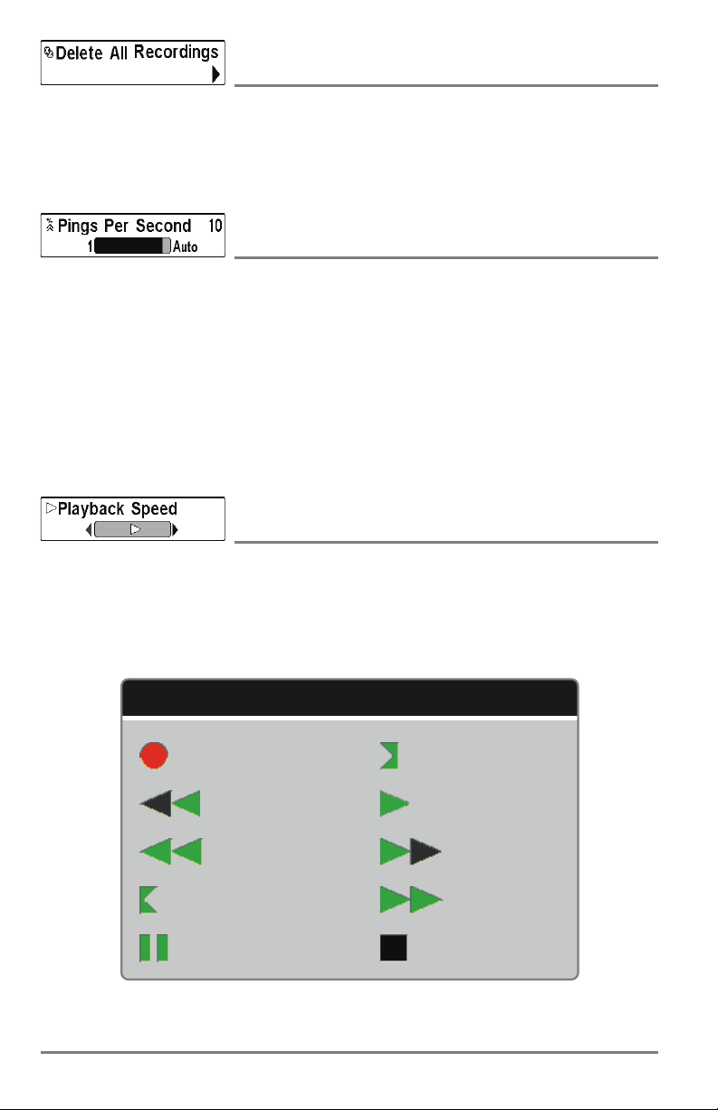
Delete All Recordings
(optional-purchase microSD Card, Snapshot and Recording View only)
Settings: Press the RIGHT Cursor key and follow screen instructions.
Delete All Recordings allows you to delete all the recordings at once. This menu option is only
available when an optional-purchase microSD card is installed and Snapshot and Recording View
is on the screen.
Pings Per Second
(optional-purchase microSD Card, Snapshot and Recording View only)
Settings: 1 to 10, Auto; Default = Auto
Pings Per Second allows you to specify the ping rate for an active sonar recording.
NOTE: Pings Per Second is available when an optional-purchase microSD card is installed, Snapshot
and Recording View is on the screen, and the control head is actively recording (not playing back).
Auto is the default setting for Pings Per Second and automatically adjusts the ping rate for best
recording quality. If there is limited memory on your microSD card, you can slow the ping rate by
setting the Pings Per Second manually, but the recording will capture less sonar detail. For
maximum performance, keep the Pings Per Second setting on Auto.
Playback Speed
(optional-purchase microSD Card, Snapshot and Recording View only)
Settings: Record, Rewind1, Rewind2, Slow Play Reverse, Pause, Slow
Play, Normal Play, Fast Forward1, Fast Forward2, Stop
Playback Speed allows you to specify the playback speed for a sonar recording from the Snapshot
and Recording View. This menu option is only available when an optional-purchase microSD card
is installed and Recording Playback is active.
Playback Speed Icons:
Record Slow Play
Rewind, Reverse Normal Play
Rewind2 Fast Forward
Slow Play Reverse Fast Forward2
Pause Stop
NOTE: You can alsochange playback speed in the Snapshot and Recording View using the LEFT and RIGHT
Cursor keys, although you cannot skip to the beginning or end of a recording using these keys.
Snapshot and Recording X-Press Menu
90
Page 97

NOTE: Sonar chart speed is increased during Fast Forward and reversed during Rewind. This may result in
a reduced quality sonar image, since at higher speeds, not every sonar return can be processed.
Stop Playback
(optional-purchase microSD Card only)
Settings: Press the RIGHT Cursor key to activate.
Stop Playback allows you to stop playback of a sonar recording from any view. This menu option
is only available when an optional-purchase microSD card is installed and Recording Playback
is active.
NOTE: During playback, the amount of time/memory left to play is indicated by the status bar. For more
information, see Views: Snapshot and Recording View.
91
Snapshot and Recording X-Press Menu
Page 98

Down Imaging X-Press Menu
Down Imaging X-Press Menu
(Down Imaging Views only [HELIX DI GPS])
The Down Imaging X-Press Menu provides a shortcut to
your most frequently-used settings. Press the MENU key
once while in any of the Down Imaging Views to access the
Down Imaging X-Press Menu.
NOTE: Menu options can be expanded or simplified by setting
the User Mode to Advanced or Normal. See Main Menu: User
Mode for details.
NOTE: Menu options are determined byyour Humminbird model.
See the following pages for full menu descriptions.
Down Imaging X-Press Menu
92
Page 99

Cancel Navigation
(only when Navigating)
Settings: Press the RIGHT Cursor key and follow screen instructions.
Cancel Navigation discards the current route and exits Navigation Mode. This menu option will
only appear when you are currently navigating a route. This will not delete a previously-saved
route.
Active Side
(Combo Views only)
Settings: Left, Right; Default = Left
Active Side allows you to select a side of the screen in a Combo View. After you choose an active
side, you can apply menu settings and key commands to the view you’ve selected. The Active Side
menu option is only available when a Combo View is on the screen (see Views: Combo Views).
• A green arrow on the Combo View points to the active side.
• When a menu is displayed in the active side, the non-active side of the screen will be
grayed out.
Split Position
(Combo Views only)
Settings: Left, 30, 40, 50, 60, 70, Right; Default = Various
Split Position sets the size of the left side of the Combo View. Each Combo View can be set
individually. The Split Position menu option is only available when a Combo View is on the screen
(see Views: Combo Views).
• The number setting indicates the percentage taken up by the left side of the Combo View.
• Selecting Left sets the left side of the screen to its smallest setting.
Down Sensitivity
Settings: 1 to 20, where Low = 1, High = 20; Default = 10
Down Sensitivity controls how the sonar returns are displayed on the Down Imaging Views.
Increase the Down Sensitivity to reveal weaker returns that may be of interest, especially in
very clear water or greater depths. A high Down Imaging Sensitivity setting shows more sonar
returns from small baitfish and suspended debris in the water; however if the Down Imaging
Sensitivity is adjusted too high, the display may become too cluttered.
Decrease the Down Sensitivity to eliminate the clutter from the display that is sometimes
present in murky or muddy water. If Down Imaging Sensitivity is adjusted too low, the display may
not show many sonar returns that could be fish.
93
Down Imaging X-Press Menu
Page 100

DI Enhance
Settings: Press the RIGHT Cursor key.
DI Enhance allows you to adjust your Down Imaging View in the following categories: Sensitivity,
Contrast, and Sharpness.
Whether you’re searching the Down Imaging data for fish or certain bottom contour, the most
effective settings will vary with the situation. The display will update as you adjust each category.
DI Enhance can also be used during Recording Playback (see Views: Snapshot and Recording
View).
DI Enhance Submenu
• Sensitivity
: Controls how much detail is shown on the display. When operating in very
clear water or greater depths, increased sensitivity shows weaker returns that may be of
interest. Decreasing the sensitivity eliminates the clutter from the display that is
sometimes present in murky or muddy water. (1 to 20, where Low = 1, High = 20;
Default = 10)
NOTE: The Sensitivity can be adjusted from the DI Enhance dialog box or the Down Imaging X-Press
Menu. The Sensitivity setting is providedhere so that you can easily adjust the Down Imaging data with
the other settings. See Down Imaging X-Pr ess Menu: Down Sensitivity for more information.
• Contrast: Accents the light and dark parts of the Down Imaging data to provide greater
definition. (1 to 20, Default = 10)
• Sharpness: Filters the view and sharpens the edges of the Down Imaging data. (Low (L),
Medium (M), High (H), Default = Off)
Upper Range
(Advanced, Down Imaging Views only)
Settings: 0 to 590 ft, 0 to 237 m (International Models only); Default = 0
Upper Range sets the shallowest depth range that will be displayed on the Down Imaging Views.
Upper Range is often used with Lower Range.
For example, if you are only interested in the area between 20 and 50 feet deep, you should
set the Upper Depth Range to 20 and the Lower Depth Range to 50. The Down Imaging View
will then show the 30 foot area between 20 and 50, and will not show the surface or the
bottom (assuming the bottom is deeper than 50 feet), and will show greater detail for that area
between 20 and 50 feet.
NOTE: A minimum distance of 10 feet will be maintained between the Upper and Lower Range
regardless of the manual settings entered.
Down Imaging X-Press Menu
94
 Loading...