

Page 1
Page 2

Thank You!
Thank you for choosing Humminbird®, the #1 name in marine electronics. Humminbird has built
its reputation by designing and manufacturing top-quality, thoroughly reliable marine equipment.
Y our Humminbird is designed for trouble-free use in even the harshest marine environment. In the
unlikely event that your Humminbird does require repairs, we offer an exclusive Service Policy. For
complete details, see the separate warranty card included with your unit. We encourage you to
read this manual carefully in order to get full benefit from all the features and applications of
your Humminbird product.
Contact Humminbird Customer Service at humminbird.com or call 1-800-633-1468.
WARNING! This device should not be used as a navigational aid to prevent collision, grounding, boat
damage, or personal injury. When the boat is moving, water depth may change too quickly to allow time
for you to react. Always operate the boat at very slow speeds if you suspect shallow water or submerged
objects.
WARNING! Disassembly and repair of this electronic unit should only be performed by authorized service
personnel. Any modification of the serial number or attempt to repair the original equipment or
accessories by unauthorized individuals will void the warranty.
WARNING! This product contains chemicals known to the State of California to cause cancer and birth
defects or other reproductive harm.
WARNING! Do not travel at high speed with the unit cover installed. Remove the unit cover before
traveling at speeds above 20 mph.
NOTE: The illustrations in this manual may not look the same as your product, but your unit will function
in the same way.
NOTE: To purchase accessories for your control head, visit our Web site at humminbird.com or contact
Customer Service at 1-800-633-1468.
NOTE: The procedures and features described in this manual are subject to change without notice. This
manual was written in English and may have been translated to another language. Humminbird is not
responsible for incorrect translations or discrepancies between documents.
NOTE: Some features discussed in this manual require a separate purchase, and some features are
only available on international models. Every effort has been made to clearly identify those features.
Please read the manual carefully in order to understand the full capabilities of your model.
ATTENTION INTERNATIONAL CUSTOMERS: Products sold in the U.S. are not intended for use in
the international market. Humminbird international units provide international features and are
designed to meet country and regional regulations. Languages, maps, time zones, units of
measurement, and warranty are examples of features that are customized for Humminbird
international units purchased through our authorized international distributors.
To obtain a list of authorized international distributors, please visit our Web site at humminbird.com
or contact Humminbird Customer Service at (334) 687-6613.
Page 3

ENVIRONMENTAL COMPLIANCE STATEMENT: It is the intention of Johnson Outdoors Marine
Electronics, Inc. to be a responsible corporate citizen, operating in compliance with known and applicable
environmental regulations, and a good neighbor in the communities where we make or sell our products.
WEEE DIRECTIVE: EU Directive 2002/96/EC “Waste of Electrical and Electronic Equipment Directive
(WEEE)” impacts most distributors, sellers, and manufacturers of consumer electronics in the European
Union. The WEEE Directive requires the producer of consumer electronics to take responsibility for the
management of waste from their products to achieve environmentally responsible disposal during the
product life cycle.
WEEE compliance may not be required in your location for electrical & electronic equipment (EEE), nor
may it be required for EEE designed and intended as fixed or temporary installation in transportation
vehicles such as automobiles, aircraft,and boats. In some European Union member states, these vehicles
are considered outside of the scope of the Directive, and EEE for those applications can be considered
excluded from the WEEE Directive requirement.
This symbol (WEEE wheelie bin) on product indicates the product must not be disposed of with
other household refuse. It must be disposed of and collected for recycling and recovery of waste
EEE. Johnson Outdoors Marine Electronics, Inc. will mark all EEE products in accordance with
the WEEE Directive. It is our goal to comply in the collection, treatment, recovery, and
environmentally sound disposal of those products; however, these requirements do vary within European
Union member states. For more information about where you should dispose of your waste equipment
for recycling and recovery and/or your European Union member state requirements, please contact your
dealer or distributor from which your product was purchased.
ROHS STATEMENT: Product designed and intended as a fixed installation or part of a system in a vessel
may be considered beyond the scope of Directive 2002/95/EC of the European Parliament and of the
Council of 27 January 2003 on the restriction of the use of certain hazardous substances in electrical and
electronic equipment.
Down Imaging®, DualBeam PLUS™, Fish ID+™, HELIX™, HumminbirdPC™, Humminbird®, Real Time Sonar™, RTS™, RTS
Window™, Structure ID™, SwitchFire®, Total Screen Update™, WhiteLine™, and X-Press™ Menu are trademarked by or
registered trademarks of Johnson Outdoors Marine Electronics, Inc.
Adobe, Acrobat, Adobe PDF, and Reader are either registered trademarks or trademarks of Adobe Systems Incorporated
in the United States and/or other countries.
Baekmuk Batang, Baekmuk Dotum, Baekmuk Gulim, and Baekmuk Headline are registered trademarks owned by Kim
Jeong-Hwan.
© 2015 Johnson Outdoors Marine Electronics, Inc. All rights reserved.
532291-2EN_B
Page 4

Table of Contents
HELIX Series Introduction 1
How Sonar Works 1
Power On 5
What’s on the Control Head 6
Key Functions 7
What’s on the Sonar Display 10
What’s on the Down Imaging Display 16
Views 20
Select a View.............................................................................................................................................. 20
Display your Favorite Views ...................................................................................................................... 20
Change Digital Readouts .......................................................................................................................... 21
Combo Views.............................................................................................................................................. 33
The Menu System 35
Start-Up Options Menu 36
X-Press Menu 39
Main Menu 40
Quick Tips for the Main Menu .................................................................................................................. 41
Note for all Menu Settings ........................................................................................................................ 41
User Mode (Normal or Advanced) ............................................................................................................ 42
Sonar X-Press Menu 44
Down Imaging X-Press Menu 49
Flasher X-Press Menu 53
Alarms Menu Tab 57
Sonar Menu Tab 60
Setup Menu Tab 70
Maintenance 77
Troubleshooting 78
HELIX Control Head Measurements 81
Specifications 85
Contact Humminbird 88
i
Page 5

Table of Contents
NOTE: Entries in this Table of Contents which list (International models only) are only available on
products sold outside of the U.S. by our authorized international distributors. To obtain a list of authorized
international distributors, please visit our Web site at humminbird.com or contact Humminbird Customer
Service at (334) 687-6613.
NOTE: Entries in this Table of Contents which list (with Speed Input) or (with Temperature Input) may
require the purchase of separate accessories. You can visit our Web site at humminbird.com to order
these accessories online or contact Humminbird Customer Service at 1-800-633-1468.
ii
Page 6

Page 7
HELIX Series Introduction
The HELIX Series Fishfinder is available in several different configurations. See the following list
of products, all of which are covered by this manual, to find your HELIX Series model:
• HELIX SONAR: Wide screen Fishfinder with DualBeam PLUS sonar.
• HELIX DI: Wide screen Fishfinder with Down Imaging sonar and traditional 2D sonar.
NOTE: Some features discussed in this manual require a separate purchase, and some features are only
available on international models. Every effort has been made to clearly identify those features. Please read
the manual carefully in order to understand the full capabilities of your model.
How Sonar Works
Sonar technology is based on sound waves. The HELIX Series Fishfinder uses sonar to locate and
define structure, bottom contour and composition, as well as depth directly below the transducer.
Your HELIX Series Fishfinder sends a sound wave signal and determines distance by measuring
the time between the transmission of the sound wave and when the sound wave is reflected off
of an object; it then uses the reflected signal to interpret location, size, and composition of an
object.
Sonar is very fast. A sound wave can travel from the surface to a
depth of 240 ft (70 m) and back again in less than 1/4 of a second.
It is unlikely that your boat can "outrun" this sonar signal.
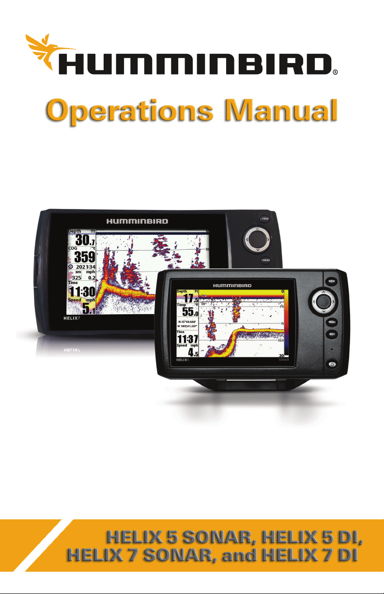
SONAR is an acronym for SOund and NAvigation Ranging. Sonar
utilizes precision sound pulses or "pings" which are emitted into
the water in a teardrop-shaped beam.
The sound pulses “echo” back from objects in the water such as
the bottom, fish, and other submerged objects. The returned
echoes are displayed on the LCD screen. Each time a new echo is
received, the old echoes are moved across the LCD, creating a
scrolling effect.
1
Introduction
Page 8
When all the echoes are viewed side by side, an easy to interpret
“graph” of the bottom, fish, and structure appears.
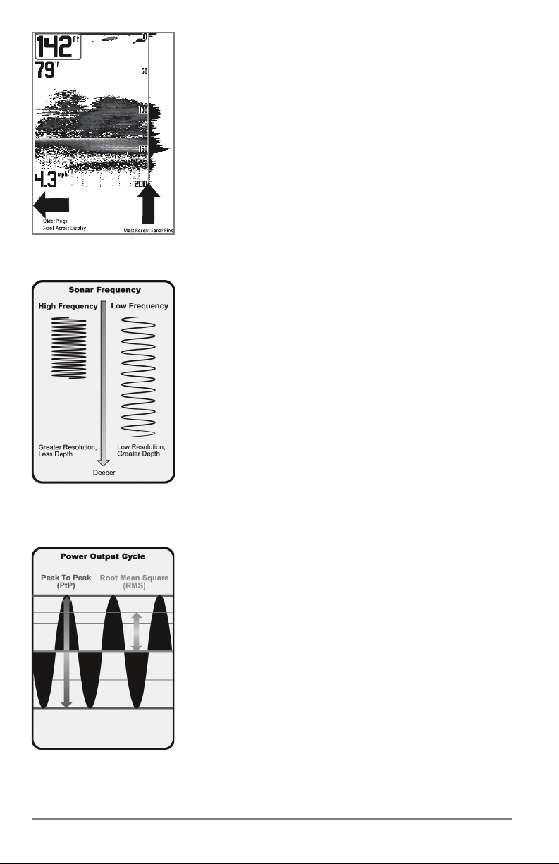
The sound pulses are transmitted at various frequencies depending
on the application. Very high frequencies (455 kHz) are used for
greatest definition but the operating depth is limited. High
frequencies (200 kHz) are commonly used on consumer sonar and
provide a good balance between depth performance and
resolution. Low frequencies (83 kHz) are typically used to achieve
greater depth capability.
Introduction
The power output is the amount of energy generated by the sonar
transmitter. It is commonly measured using two methods:
• Root Mean Square (RMS) measures power output over the
entire transmit cycle.
• Peak to Peak measures power output at the highest points.
The benefits of increased power output are the ability to detect
smaller targets at greater distances, ability to overcome noise,
better high speed performance, and enhanced depth capability.
2
Page 9
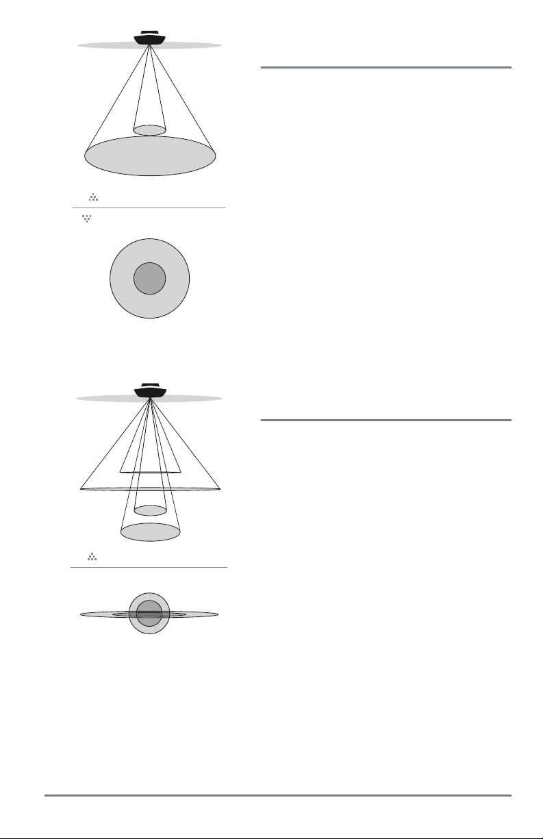
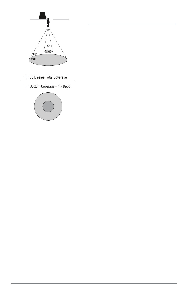
20˚
60˚
200kHz
83kHz
60 Degree Total Coverage
Bottom Coverage = 1 x Depth
DualBeam PLUS Sonar
(HELIX SONAR)
The HELIX SONAR Fishfinder uses a 200/83 kHz
DualBeam PLUS sonar system with a wide (60°) area
of coverage. DualBeam PLUS sonar has a narrowly
focused 20° center beam, surrounded by a second
beam of 60°, expanding your coverage to an area
equal to your depth. In 20 feet of water, the wider
beam covers an area 20 feet wide.
DualBeam PLUS sonar returns can be blended
together, viewed separately, or compared side-byside. DualBeam PLUS is ideal for a wide range of
conditions - from shallow to very deep water in both
fresh and salt water. Depth capability is affected by
such factors as boat speed, wave action, bottom
hardness, water conditions, and transducer
installation.
Down Imaging Sonar
(HELIX DI)
28°
16°
455kHz
200kHz
800kHz
45°
455kHz
75 Degree Total Coverage
75°
The HELIX DI Fishfinder uses Down Imaging
technology. The Down Imaging transducer scans the
water with razor-thin, high-definition beams. The
beams are wide (side to side) but very thin front to
back.
The Down Imaging beams can be operated at two
frequencies: 455 kHz (75°) or 800 kHz (45°). Select
455 kHz for the best overall image quality and depth.
Select 800 kHz for the sharpest image. See Sonar
Menu Tab: Imaging Frequency for more information.
The transducer also uses conical beams to provide data
in traditional 2D format (see What’s on the Sonar
Display). Select 455 kHz for a narrowly focused 16°
center beam, or select 200 kHz for a wider 28° beam
(see Sonar Menu Tab: Beam Select).
Depth capability is affected by such factors as boat
speed, wave action, bottom hardness, water
conditions, and transducer installation.
3
Introduction
Page 10
Dual Beam Ice Transducer
(with optional-purchase XI 9 20 Ice Transducer)
The XI 9 20 Ice Transducer provides selectable dualfrequency sonar with a wide area of coverage.
Selectable dual-frequency gives you the option of
two beams, and both beams will cover the bottom
and provide high definition. The 20° center beam
provides the highest definition, while the 60° beam
provides wider coverage.
Depth capability is affected by such factors as
bottom hardness and water conditions. Whether
fishing in shallow or very deep water, selectable
dual-frequency is ideal for a variety of conditions.
NOTE: Visit our Web site at humminbird.com to
determine which accessory transducers are compatible
with your Humminbird Fishfinder, or contact Customer
Service at 1-800-633-1468.
Introduction
4
Page 11

Power On
Follow the instructions below to power on your Humminbird control head.
HELIX Series Title Screen
1. Press the POWER/LIGHT key.
2. When the Title screen is displayed, press the MENU key to access the Start-Up Options
Menu.
3. Select Normal, and press the RIGHT Cursor key.
• If you wait too long to select a Start-Up Option, the system will default to whichever
menu is already highlighted.
• If a functioning transducer is connected, Normal operation will be selected
automatically, and your control head can be used on the water.
• You can also select Simulator to learn how to use your control head and save settings
in advance for later use. See Start-Up Options Menu for more information.
4. Quick Setup: If this is the first time the unit has been powered on (after installation or
after restoring defaults), the Quick Setup dialog box will display on the screen. Use the
4-WAY Cursor Control key to change the settings. Press the EXIT key to close the dialog
box.
NOTE: The Quick Setup settings can be changed at any time. See each menu option in The Menu System
for details.
5
Power On
Page 12
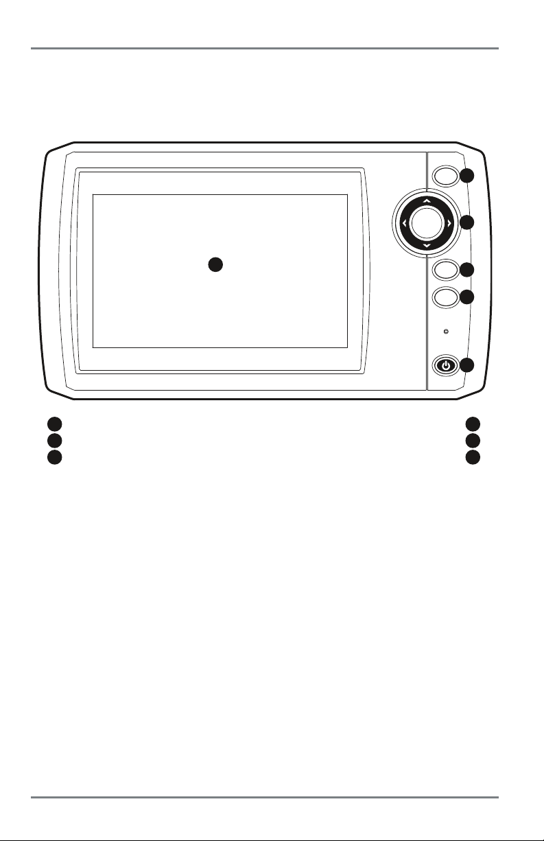
What’s on the Control Head
Your HELIX Series user interface is easy to use. A combination of keys, different views, and
situation-specific, customizable menus allows you to control what you see on the color display.
Refer to the following illustration and see Key Functions, Views,andThe Menu System for more
information.
VIEW
2
3
1
screen
2
VIEW key
4-WAY Cursor Control key (LEFT, RIGHT, UP, or DOWN)
3
1
MENU
EXIT
4
5
6
EXIT key
4
5
6
MENU key
POWER/LIGHT key
What’s on the Control Head
6
Page 13
Key Functions
Y our control head consists of a set of easy-to-use keys that work with various on-screen views and
menus.
POWER/LIGHT Key
The POWER/LIGHT key is used to power the Fishfinder on and off. Y ou can also use
the POWER/LIGHT key to adjust the backlight and contrast of the display.
Power On: Press the POWER/LIGHT key to power on the unit. When the Title screen is displayed,
press the MENU key to access the Start-Up Options Menu.
Power Off: Press and hold the POWER/LIGHT key for 3 seconds. A message will appear to indicate
how many seconds there are until shutdown occurs. To ensure that shutdown occurs properly and
any menu settings will be saved, your Fishfinder should always be turned off using the
POWER/LIGHT key.
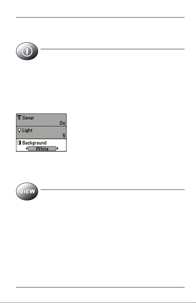
Adjust the Backlight or the Display Background Color: Press the
POWER/LIGHT key to access the Light and Background submenu.
Use the 4-WAY Cursor Control key to select Light or Background,
and then use the LEFT or RIGHT Cursor key to change the settings.
Press EXIT to exit the Light and Background submenu.
Turn Sonar On or Off: From the Light and Background submenu, use the 4-WAY Cursor Control
key to select Sonar. Use the LEFT or RIGHT Cursor key to change the setting. See Setup Menu Tab:
Sonar for more information.
VIEW Key
The VIEW key is used to cycle through all available views. Press the VIEW key to
advance to the next view. Press the VIEW key repeatedly to cycle through all
available views. Views can be hidden to optimize the system to your fishing
requirements (see Views or Setup Menu T ab: Select Views).
NOTE: Press the EXIT key to cycle through the views in reverse order.
7
Key Functions
Page 14

MENU Key
The MENU key is used to access the menu system. See The Menu System for more
information.
Start-Up Options Menu: Press the MENU key during the power up sequence to view the Start-Up
Options menu.
X-Press Menu: Press the MENU key once in any view to access the X-Press Menu, which provides
frequently-used menu settings that correspond with the current view.
Main Menu: Press the MENU key twice in any view to access the Main Menu, which is organized
under tabbed headings to help you find a specific menu item quickly.
4-WAY Cursor Control Key
(RIGHT, LEFT, UP, or DOWN Cursor Keys)
The 4-WAY Cursor Control key has multiple functions, which depend on the
view, menu, or situation.
• Menu Selection: Press the DOWN or UP Cursor keys to highlight a menu option, then
press the RIGHT or LEFT Cursor keys to change a menu setting. The changes will be
activated and saved immediately.
• Freeze Frame: In Sonar Views and Down Imaging Views, press any arrow on the 4-WAY
Cursor Control key to freeze the display and move the active cursor to a location on the
screen. A cursor dialog box will display to show the depth of the location you choose.
• Active Cursor: Press any arrow on the 4-WAY Cursor Control key, and the active cursor
will appear on the screen.
NOTE: In Freeze Frame or Active Cursor mode, you can also make the cursor move diagonally
by pressing in between two of the arrows on the 4-WAY Cursor Control key.
• Circular Flasher View (Ice Fishing Mode: On): Press the UP or DOWN Cursor keys to
move the Depth Cursor. Press the RIGHT or LEFT Cursor keys to adjust the Zoom Range
(see Views: Circular Flasher View).
Key Functions
8
Page 15

EXIT Key
The EXIT key has multiple functions, which depend on the situation.
• If an alarm is sounding, press the EXIT key to cancel the alarm.
• If a menu tab is selected, press the EXIT key to exit the menu mode and return to the view .
• Ifamenuisactive,press the EXIT key to return to the previous level in the menu system.
• From any view, press the EXIT key to cycle through the available views in reverse order.
• If Freeze Frame is active, press the EXIT key to return to a scrolling display.
• If the Cursor is active, press the EXIT key to remove the cursor from the display.
• If Down Imaging Zoom is active, press the EXIT key to remove the magnification box
from the display and remove the cursor.
9
Key Functions
Page 16
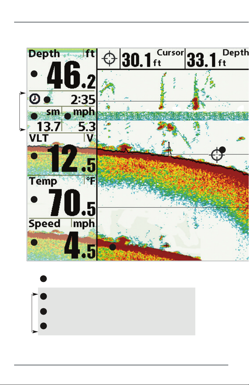
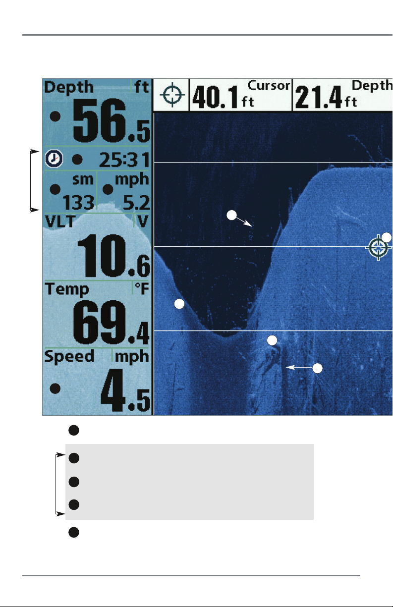
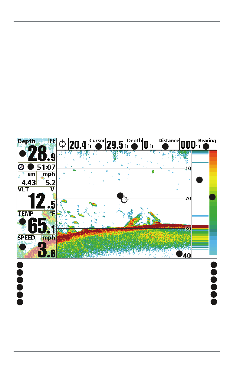
What’s on the Sonar Display
The Fishfinder can display a variety of useful information about the area under and adjacent to
1
2
Triplog
3
5
6
7
1
2
4
12
Depth - Water depth can be set to alarm when the water becomes too shallow.
Timer - Elapsed time with Speed accessory or GPS receiver
13
.
3
Distance - Distance traveled with Speed accessory or GPS receiver
Triplog
4
Average Speed - Average speed reading with Speed accessory or GPS receiver
What’s on the Sonar Display
.
.
10
Page 17
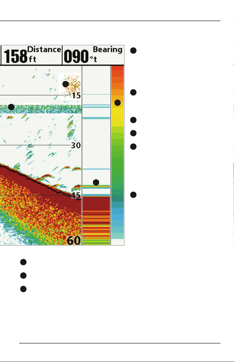
your boat, including the following items:
10
8
11
8
Thermoclines - Layers of water with different
temperatures that appear at different depths and
different times of the year. A thermocline typically
appears as a continuous band of many colors moving
across the display at the same depth.
9
Sonar Color Bar - Color spectrum indicating low
9
to high sonar intensity returns, where red indicates
high intensity and white indicates low intensity.
10
Bait Ball
11
RTS (Real Time Sonar) Window
12
Second Sonar Return - When the sonar signal
bounces between the bottom and the surface of the
water and back again. Use the appearance of the
second return to determine bottom hardness. Hard
bottoms will show a strong second return, while soft
bottoms will show a very weak one or none at all.
13
Cursor - Available in Freeze Frame and can be
positioned in the Sonar View to provide depth of a
sonar return and bottom depth below the cursor. The
Latitude and Longitude of the cursor position, the
distance to travel to the cursor position, and the
bearing to the cursor position are shown with a
connected GPS receiver. Cursor information is
displayed at the top of the screen.
5
Voltage - Power supplied to the control head.
6
Temperature - Water surface temperature.
7
Speed - If a Speed accessory or GPS receiver is connected,
the Fishfinder can display the speed of the boat, and can keep
a triplog of nautical or statute miles traveled.
11
What’s on the Sonar Display
Page 18
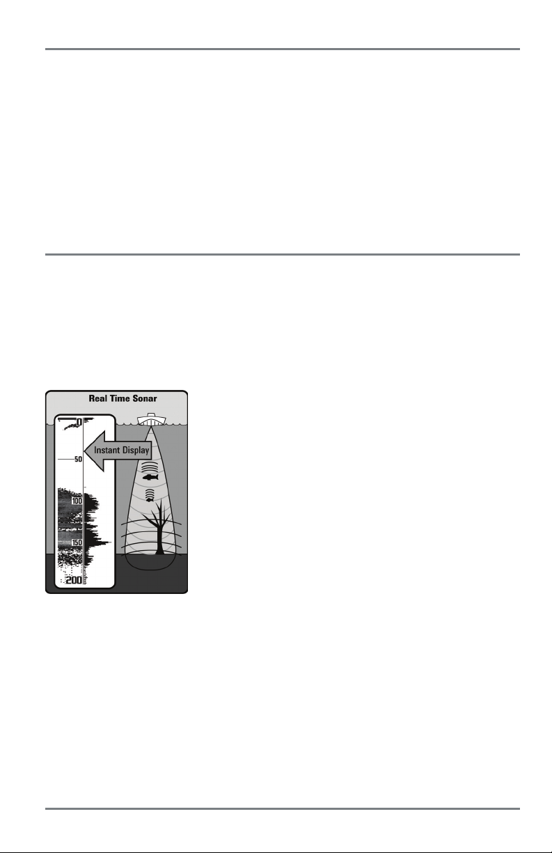
Understanding the Sonar Display
It is important to understand the significance of the display. The
display does NOT show a literal 3-dimensional representation of
what is under the water. Each vertical band of data received by the
control head and plotted on the display represents something that
was detected by a sonar return at a particular time. As both the
boat and the targets (fish) may be moving, the returns are only
showing a particular segment of time when objects were detected,
not exactly where those objects are in relation to other objects
shown on the display.
The returned sonar echoes are displayed on the screen. As a new
echo is received, the historical data scrolls left across the display.
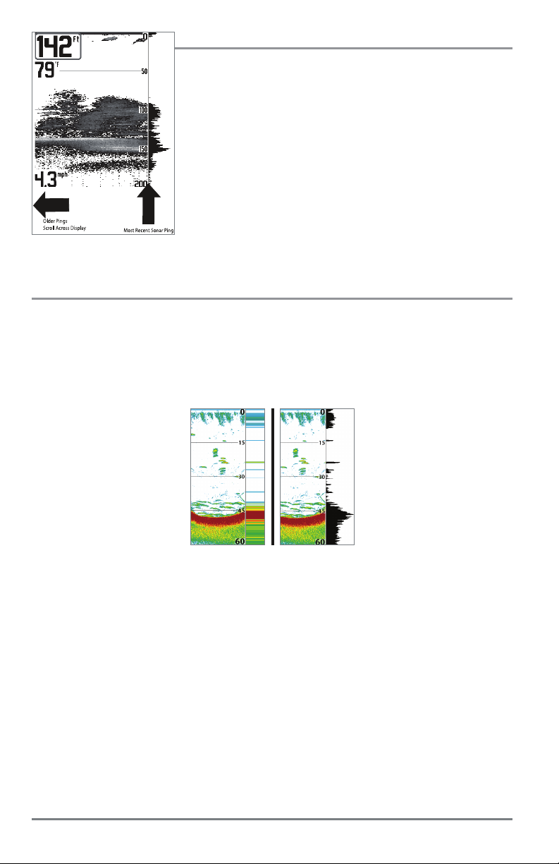
Real Time Sonar (RTS) Window
A Real Time Sonar (RTS) Window appears on the right side of the display in the Sonar Views only.
The RTS Window always updates at the fastest rate possible for depth conditions and shows only the
returns from the bottom, structure and fish that are within the transducer beam. The RTS Window
plots the depth and intensity of a sonar return. (See Sonar Menu Tab: Real Time Sonar (RTS)
Window).
The Narrow RTS Window
indicates the sonar intensity
through the use of colors. Red
indicates a strong return and
blue indicates a weak return.
The depth of the sonar return
is indicated by the vertical
placement of the return on
the display depth scale.
The Wide RTS Window
indicates the sonar intensity
throughtheuseofabar
graph. The length of the
plotted return provides an
indication of whether the
return is weak or strong. The
depth of the sonar return is
indicated by the vertical
placement of the return on
the display depth scale. The
Wide RTS Window does not
use grayscale.
What’s on the Sonar Display
12
Page 19
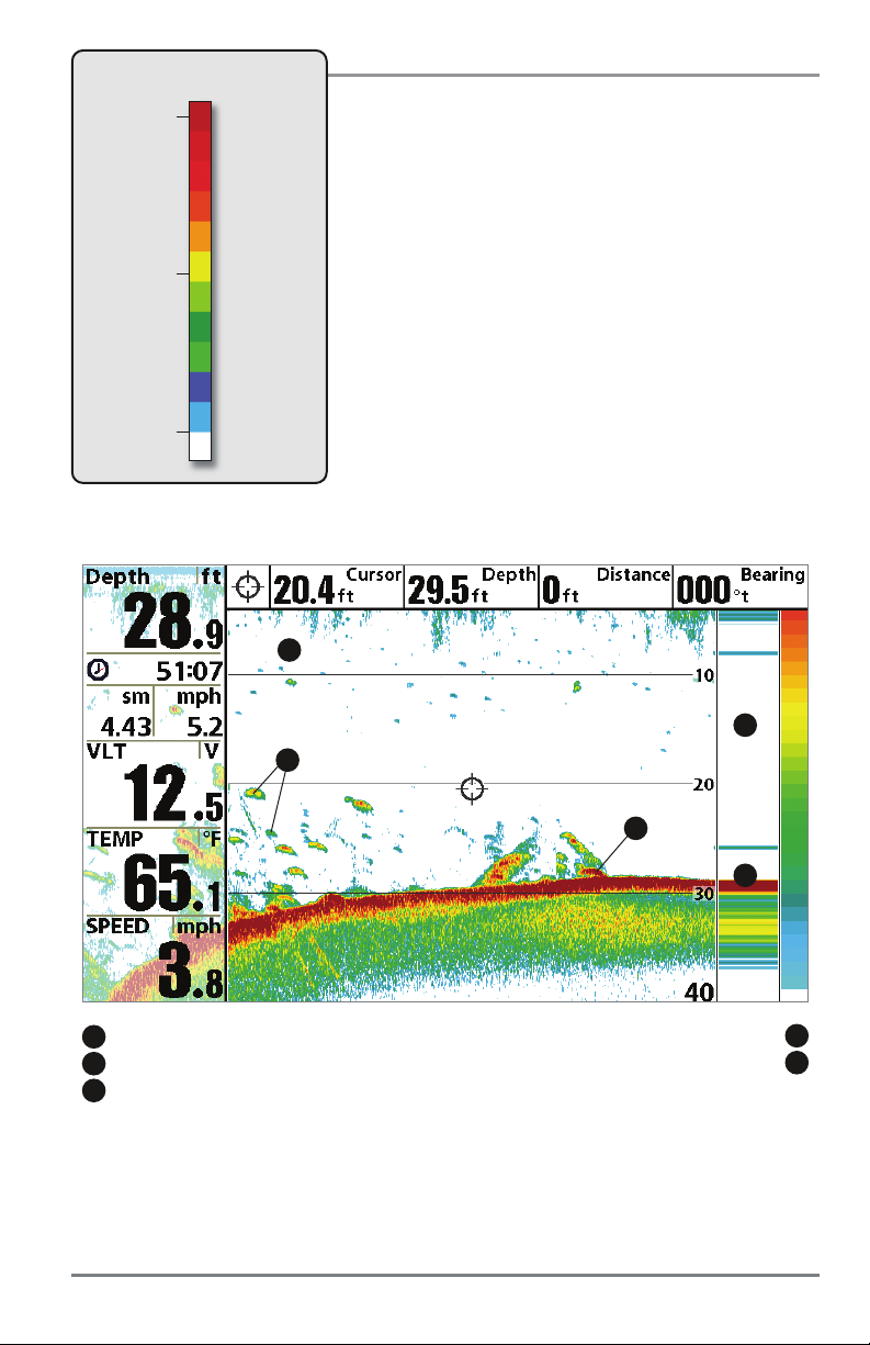
Sonar Colors: Original Palette
HIGH
Intensity Return
MEDIUM
Intensity Return
LOW
Intensity Return
Sonar Colors and Bottom View
As the boat moves, the unit charts the changes in depth on
the display to create a profile of the Bottom Contour.The
Sonar View displays the sonar return intensity with different
colors.
Strong returns often result from rocky or hard bottoms
(compacted sediment, rocks, fallen trees), while weaker
returns often result from soft bottoms (sand, mud), vegetation,
and small fish.
The colors used to represent high, medium, to low intensity
returns are determined by the palette you choose in the Sonar
Colors menu option. See Sonar Menu Tab to set the Sonar
Colors.
Sonar View: Original Palette
1
5
3
2
4
sonar history: historical returns scroll left across the view strong return (possibly compacted sediment or rocks)
1
strong returns (possibly rocks, tree limbs, or other structure)
2
weak returns (possibly vegetation or small fish)
3
RTS window
4
5
Use Bottom View to select the method used to represent bottom and structure on the display.
See Sonar Menu to set the Bottom View.
13
What’s on the Sonar Display
Page 20
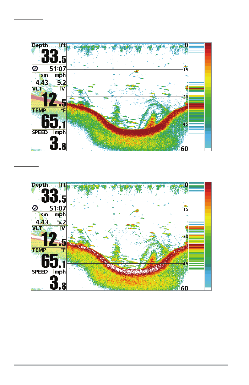
Structure ID represents weak returns in blue and strong returns in red when Sonar Colors is set
to Original. If the Sonar Colors palette is changed, the Structure ID will display the strongest
return as specified by the palette. See Sonar Menu Tab: Sonar Colors for more information.
WhiteLine highlights the strongest sonar returns in white, resulting in a distinctive outline. This
has the benefit of clearly defining the bottom on the display.
What’s on the Sonar Display
14
Page 21

SwitchFire
SwitchFire controls how the sonar returns are displayed in the Sonar Views. SwitchFire settings
are available in the Sonar Menu Tab.
To see the maximum sonar information available within the transducer beam so more fish arches
and better jig tracking are shown, choose Max Mode.
To see less clutter and more fish size accuracy interpreted from the transducer beam, choose
Clear Mode. See Sonar Menu Tab: SwitchFire for more information.
Freeze Frame and Active Cursor
Freeze Frame & Active Cursor - Press any arrow on the 4-WAY Cursor Control key, and the screen
will freeze and a cursor will be displayed. Use the 4-WAY Cursor Control key to move the cursor
over a sonar return, and the depth of the sonar return will be displayed in the cursor dialog box.
The RTS Window continues to update in Freeze Frame. To return to a scrolling display and exit
Freeze Frame, press the EXIT key. Freeze Frame is available in the Sonar, Split Sonar, and Sonar
Zoom Views.
Instant Image Update
Instant Image Update - You can change a variety of sonar menu settings (such as Sensitivity or
Upper Range), and the adjustments will be shown instantly on the screen.
15
What’s on the Sonar Display
Page 22
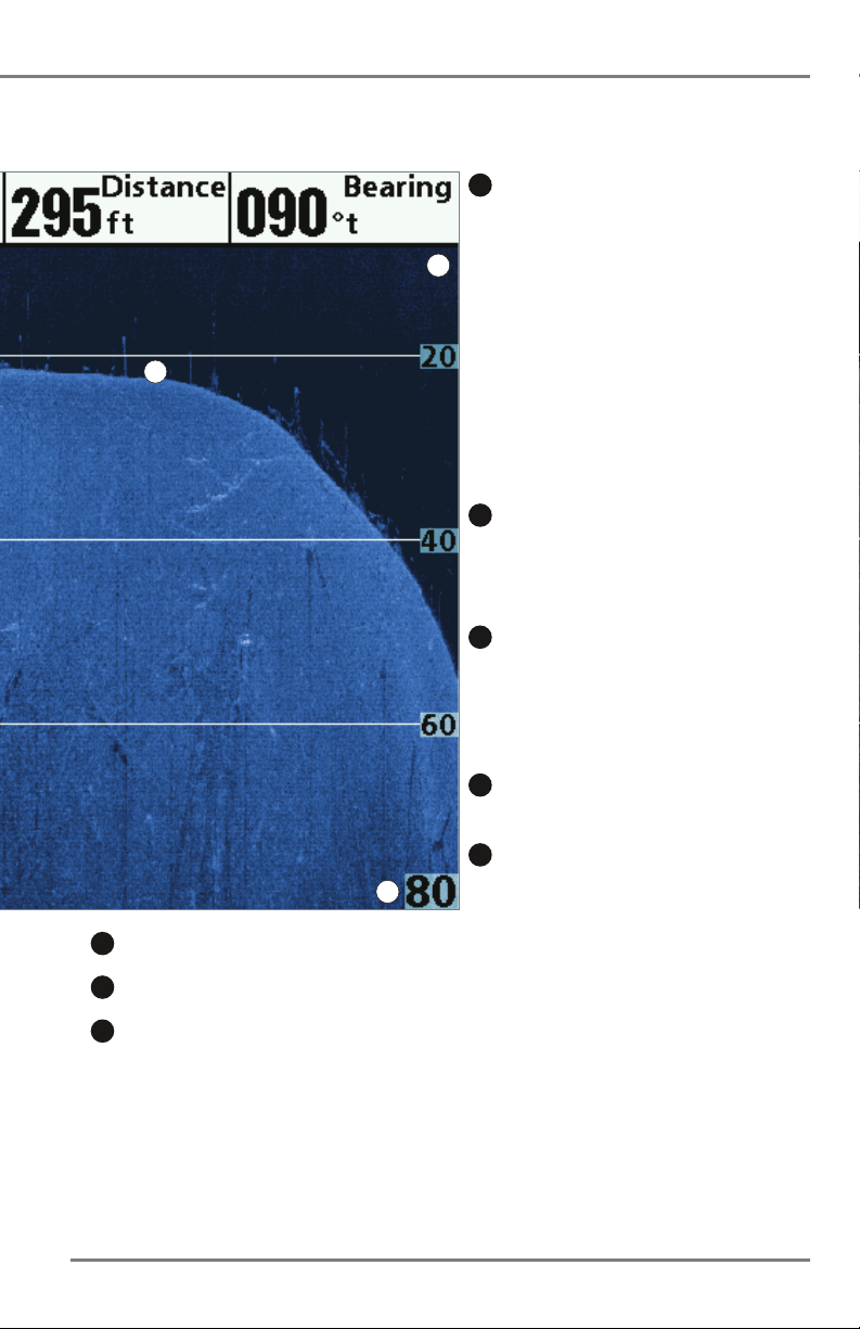
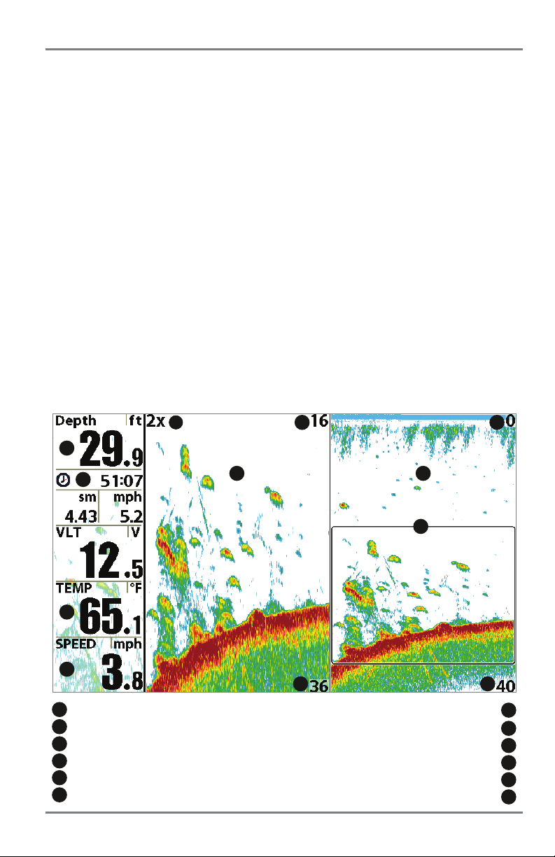
What’s on the Down Imaging Display
Down Imaging uses unique sonar technology to provide information about the area directly below
you see on the display. Down Imaging reveals a variety of recognizable features so that you can
1
2
Triplog
3
4
13
10
12
5
1
Depth - Water depth can be set to alarm when the water becomes too shallow.
2
Timer - Elapsed time with Speed accessory or GPS receiver
3
Distance - Distance traveled with Speed accessory or GPS receiver
Triplog
4
Average Speed - Average speed reading with Speed accessory or GPS receiver
5
Speed - If a GPS Receiver or Temp/Speed accessory is connected, the Fishfinder
can display the speed of the boat and can keep a Triplog of nautical or statute miles
traveled.
What’s on the Down Imaging Display
8
9
.
.
.
16
Page 23
(HELIX DI only)
your boat. The razor-thin, high-definition profiling beams produce the detailed sonar data that
interpret the structure and bottom contour, including the following items:
9
Shadows - result from a lack of reflected sonar
from a particular area and can be as valuable for
interpretation than the sonar reflected by the object
6
itself. Use shadows to help you see the image in 3
dimensions, oriented in space. You can gain insight
into the actual shape of an object, or the depth to
which it has sunk into the bottom, through shadows
11
on the display. Objects standing on the bottom cast
a sonar shadow. The longer the shadow, the taller the
object. Fish also cast shadows. You can use the
shadow to interpret how close the fish is to the
bottom.
10
Topography Changes - The light part of the
display shows where the beam is hitting hard bottom
or rising terrain. The dark part of the display indicates
soft bottom (sand, mud) or descending terrain.
11
Bottom Return - Use the appearance of the
bottom return to determine bottom hardness. Rock
and gravel provide a clearer sonar return than mud
and sand because hard objects reflect sonar better
than soft objects.
12
Freeze Frame - Use the 4-WAY Cursor Control key
to move the cursor to an area on the screen.
13
Clouded Area may indicate a bait ball and White
7
6
Upper Range
7
Lower Range
8
Structure
NOTE: Entries in this view that list (with Temp/Speed or GPS receiver) are available if either device is
connected to the HELIX Series Fishfinder. If both devices are connected, then only the information from the
GPS receiver will be displayed on the view.
17
Streaks may indicate fish.
What’s on the Down Imaging Display
Page 24

Understanding the Down Imaging Display
The images you see on the Down Imaging display are
produced using sonar technology. Each time the unit
pings, a strip of data representing all the echoes
received by the transducer are put together on the
display to form the image that you see. Like traditional
2D sonar, the sonar history scrolls left across the
screen.
Interpreting the Display
Down Imaging beams “illuminate” the bottom contour, structure, and fish. The beams are wide
(side to side) but very thin front to back.
Use the light and dark parts of the display to interpret the objects under your boat as follows:
• Dark shades represent soft returns (mud, sand) or descending terrain.
• Light shades represent denser terrain (timber, rocks) or rising terrain. A very hard bottom
may appear as white on the display.
• White Streaks or Clouds may represent fish on the display.
• Shadows are not caused by light but by the lack of a sonar return. Objects standing on
the bottom cause a sonar shadow to appear on the display. The longer the shadow, the
taller the object. Fish may also cast shadows. You can use the shadow to interpret where
the fish or object is located in relation to the bottom.
What’s on the Down Imaging Display
18
18
Page 25

Down Imaging Sensitivity
Use Down Sensitivity to control how the sonar returns appear on the display. Increase the
sensitivity to reveal weaker returns that may be of interest, especially in very clear water or greater
depths. Decrease the sensitivity to eliminate the clutter from the display that is sometimes present
in murky or muddy water. See the Down Imaging X-Press Menu: Down Sensitivity for more
information.
Freeze Frame and Active Cursor
Freeze Frame and Active Cursor: Press any arrow on the 4-WAY Cursor Control key, and the
screen will freeze and a cursor will be displayed. Use the 4-WAY Cursor Control key to move the
cursor over a sonar return, and the depth of the sonar return will be displayed in the cursor dialog
box.
DI Zoom: Use DI Zoom to see returns near the cursor location at a higher magnification. For more
information, see Views: Down Imaging View.
19
What’s on the Down Imaging Display
Page 26
Views
The sonar information from your Fishfinder is displayed on the screen in a variety
of easy-to-read views. There are many views available on your Fishfinder.
Select a View
The available views on your Humminbird unit will vary with the model you’ve purchased and the
transducer attached to the control head. See Setup Menu Tab: Select Views and the following
pages for more information.
Next View: Press the VIEW key to advance to the next view in the View
Rotation. Press the VIEW key repeatedly until the view you want to use
is displayed on the screen.
Previous View: Press the EXIT key to see the previous view in the View
Rotation. Press the EXIT key repeatedly until the view you want to use is
displayed on the screen.
Display your Favorite Views
You can display or hide any view so that each time you press the VIEW key, only your favorite views
are displayed on the screen.
1. Press the MENU key twice to open the Main Menu.
2. Press the RIGHT Cursor key until the Views tab is selected.
3. Press the UP or DOWN Cursor keys to select a view.
4. Press the LEFT or RIGHT Cursor keys to select Hidden or Visible.
Views
20
Page 27
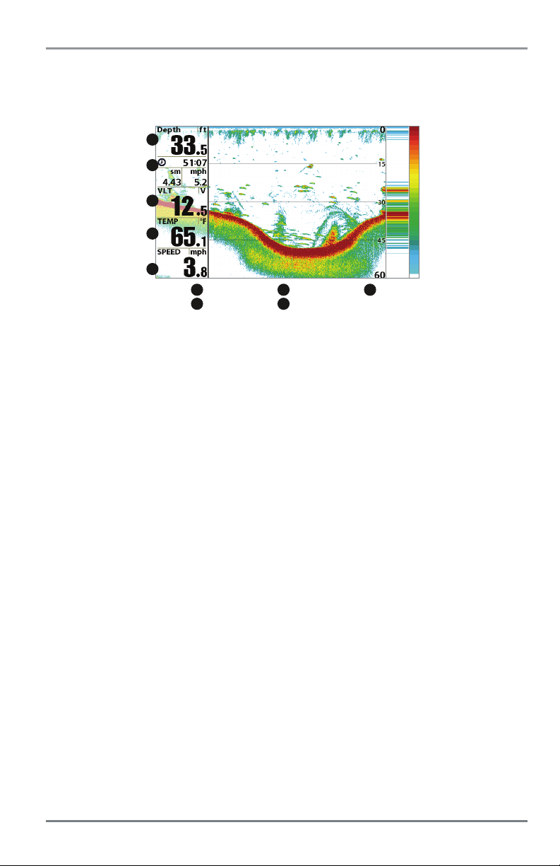
Change Digital Readouts
Each view displays digital readout information (such as speed or time), which varies with the
view displayed on-screen and connected accessories.
Sonar View
1
2
3
4
5
1
readout 1
2
readout 2
In Sonar View, Sonar Zoom View, Split Sonar View, and Down Imaging View, you can choose
which digital readouts you want to display. See Setup Menu Tab: Select Readouts for more
information.
1. Press the MENU key twice to open the Main Menu. Press the RIGHT Cursor key until the
Setup tab is selected.
2. Press the DOWN Cursor key to highlight Select Readouts, and press the RIGHT Cursor key.
3
4
readout 3
readout 4
5
readout 5
NOTE: If the Select Readouts option does not appear under the Setup Tab, change the User Mode
to Advanced (Setup tab > User Mode > Advanced).
3. Press the UP or DOWN Cursor keys to select a Readout window. Press the RIGHT or LEFT
Cursor keys to choose a digital readout.
Blank: To hide a data window, select Off.
21
Views
Page 28
Sonar View
Sonar View presents a historical log of sonar returns. The most recent sonar returns are charted
on the right side of the display. As new information is received, the historical information scrolls
left across the display.
• Upper and Lower Depth Range numbers indicate the distance from the surface of the
water to a depth range sufficient to show the bottom.
• Depth is automatically selected to keep the bottom visible on the display, although you
can adjust it manually as well (see Sonar X-Press Menu).
• Digital Readouts shown on the display will change based on the Select Readouts settings
or the optional-purchase accessories attached (see Setup Menu Tab: Select Readouts).
• Freeze Frame: Use the 4-WAY Cursor Control key to freeze the display and move the cursor
over a sonar return. The depth of the sonar return will be displayed at the top of the screen
in the cursor dialog box.
Sonar View
6
1
2
3
4
depth depth below cursor
1
triplog
2
temperature
3
speed
4
cursor
5
depth of cursor
6
7
5
8
9
10
12
distance to cursor
bearing to cursor
RTS window
sonar color bar
lower depth range
NOTE: If the Depth number is flashing, it means that the unit is having trouble locating the bottom. This
usually happens if the water is too deep, the transducer is out of the water, the boat is moving too fast, or
for any other reason that the unit can’t accurately receive continuous data.
11
7
8
9
10
11
12
Views
22
Page 29
Sonar Zoom View
Sonar Zoom View provides a magnified view of the bottom and structure. The Sonar Zoom View
makes it easier to see separate sonar returns that would usually be displayed close together,
such as those caused by fish suspended close to the bottom or within structure.
•TheZoom Level, or magnification, is displayed in the top left corner of the display. Press the
MENU key once to access the Sonar X-Press Menu. Highlight Zoom Level, and press the LEFT
or RIGHT Cursor keys to adjust the Zoom Level.
•TheZoomed View is displayed on the left side of the screen. As the depth changes, the
zoomed view updates automatically.
•TheFull Range View is displayed on the right side of the screen. The Full Range View includes
the Zoom Preview Box, which shows where the zoomed view is in relation to the full range
view.
•TheUpper and Lower Depth Range numbers indicate the high and low range of the water
which is being viewed.
• Digital Readouts shown on the display will change based on the Select Readouts settings
or the optional-purchase accessories attached (see Setup Menu T ab: Select Readouts).
• Freeze Frame: Use the 4-WAY Cursor Control key to freeze the display and move the cursor
over a sonar return. The depth of the sonar return will be displayed in the cursor dialog box.
Sonar Zoom View
1
3
4
1
depth
2
triplog
3
temperature
4
speed
5
zoomed view
6
zoom level
6
2
5
23
8
10
9
upper depth range, full range view
upper depth range, zoom view
zoom preview box
full range view
lower depth range, full range view
lower depth range, zoom view
7
1112
7
8
9
10
11
12
Views
Page 30

Split Sonar View
Split Sonar View displays sonar returns from each down beam frequency on separate sides of
the screen. You can use the Split Sonar View to make side by side comparisons between the
sonar returns from both beams.
• HELIX SONAR models display sonar returns from the 83 kHz wide beam on the left side
of the screen and sonar returns from the 200 kHz narrow beam on the right side of the
screen.
• HELIX DI models display traditional 2D sonar returns from the 455 kHz narrow beam on
the left side of the screen and sonar returns from the 200 kHz wide beam on the right side
of the screen.
• Digital Readouts shown on the display will change based on the Select Readouts settings
or the optional-purchase accessories attached (see Setup Menu Tab: Select Readouts).
• Freeze Frame: Use the 4-WAY Cursor Control key to freeze the display and move the cursor
over a sonar return. The depth of the sonar return will be displayed in the cursor dialog
box.
Split Sonar View (HELIX SONAR)
5
1
2
3
8
4
1
depth upper depth range
2
triplog
3
temperature
4
speed
Views
24
7
200 kHz sonar history window
83 kHz sonar history window
lower depth range
6
5
6
7
8
Page 31

Big Digits View
Big Digits View provides digital depth data in a large, easy-to-see format.
• Digital Readouts: Depth and Temperature are always displayed. The Speed readout is
displayed automatically if the appropriate accessory is connected to the Fishfinder.
• The digital readouts in the Big Digits View cannot be customized.
Big Digits View (HELIX SONAR)
1
2
3
1
2
3
depth
temperature
speed
25
Views
Page 32

Down Imaging View (HELIX DI only)
Down Imaging View uses the razor-thin, high-definition profiling beams to produce the detailed
sonar data that you see on the display. Sonar returns are charted on the right side of the display.
As new information is received, the historical information scrolls left across the display. See
What’s on the Down Imaging Display for more information.
• Down Imaging X-Press Menu: Press the MENU key once to access the Down Imaging
X-Press Menu. You can set the sensitivity of the sonar to see more or less detail, the chart
scrolling speed, the display color palette, and the Upper Range and Lower Range (see
Down Imaging X-Press Menu).
• Freeze Frame: Press any arrow on the 4-WAY Cursor Control key and the Down Imaging
View will freeze and a cursor will appear on the screen. Use the 4-WAY Cursor Control key
to move the cursor over a sonar return, and observe the following:
-Thedepth of the sonar return you choose will be displayed in the cursor information
box.
- Zoom: Press the MENU key to open the Down Imaging X-Press Menu and select DI
Zoom. Press the LEFT or RIGHT Cursor keys to select the zoom level. A zoom box will
appear and magnify the area you choose. The zoom level will appear in the cursor
information box. Press EXIT to remove the zoom box and return to Down Imaging
View.
Down Imaging View
8
1
2
3
5
1
depth
2
water surface temperature
3
voltage
4
triplog
5
speed
Views
4
6
7
9
bottom return
topography changes
upper range
lower range
6
7
8
9
26
Page 33

Down Imaging View with Active Cursor and Zoom
6
1
2
3
4
5
1
depth
2
water surface temperature
3
voltage
4
triplog
5
speed
7
8
9
cursor information box
zoom magnification box
zoomed view
lower range
6
7
8
9
27
Views
Page 34

Circular Flasher View
Circular Flasher View provides two ways to view sonar data in traditional flasher format. The view
is controlled by the Ice Fishing Mode menu option in the Sonar Menu Tab.
• When Ice Fishing Mode is off, the Circular Flasher View displays Real Time Sonar (RTS)
data in a traditional flasher format.
• When Ice Fishing Mode is on, the Circular Flasher View displays the sonar data in
traditional flasher format with additional features, including Zoom and Depth Cursor.
Set the Circular Flasher View Mode:
1. Press the MENU key twice.
2. Press the RIGHT Cursor key until the Sonar Menu Tab is selected.
3. Press the DOWN Cursor key to select Ice Fishing Mode.
4. Press the RIGHT or LEFT Cursor key to select On or Off (default = Off). See Sonar Menu
Tab for more information.
Set the Digital Depth Source (HELIX DI only):
If you connect an ice transducer to the control head, set the Digital Depth Source to 2D Element
to display depth in the digital readout window. See Sonar Menu Tab: Digital Depth Source for
more information.
1. Press the MENU key twice.
2. Press the RIGHT Cursor key until the Sonar Menu Tab is selected.
3. Press the DOWN Cursor key to select Digital Depth Source.
4. Press the RIGHT or LEFT Cursor key to select 2D Element.
Views
28
Page 35

Ice Fishing Mode: Off
When Ice Fishing Mode is off, the Circular Flasher View displays Real Time Sonar (RTS) data in
a traditional flasher format.
• Flasher X-Press Menu: Press the MENU key once in the Circular Flasher View. Use the
X-Press Menu to set the Sensitivity, Upper Range, and Lower Range.
• Depth and temperature are always displayed.
•TheDigital Readouts cannot be customized.
Circular Flasher View (Ice Fishing Mode: Off)
3
1
2
flasher dial
depth
1
2
4
speed
3
water surface temperature
4
29
Views
Page 36

Ice Fishing Mode: On
When Ice Fishing Mode is on, the Circular Flasher View displays the sonar data in traditional
flasher format with additional features, including Zoom and Depth Cursor.
• Sensitivity: When you turn on Ice Fishing Mode, the fishfinder’s sensitivity settings are
adjusted automatically to accommodate ice fishing conditions. These settings will apply
to the other Sonar Views until you turn off Ice Fishing Mode (see Set the Circular Flasher
View Mode in this section).
• Flasher X-Press Menu: Press the MENU key once in the Circular Flasher View. Use the
X-Press Menu to set the Sensitivity, Upper Range, Lower Range, and Color Palette.
• Color Palettes: The color preview bar in the center of the display indicates the current
palette, and the weak to strong sonar return range is displayed from left to right. To change
the color palette, see Flasher X-Press Menu: Color Palette.
•TheDigital Readouts cannot be customized.
Circular Flasher View (Ice Fishing Mode: On)
1
2
4
1
battery icon indicates the percentage of battery power
2
flasher dial
3
current color palette
4
sensitivity (see Flasher X-Press Menu)
5
zoom setting
5
6
3
7
8
9
depth
6
units of measurement
beam select (see Sonar Menu Tab)
noise filter (see Sonar Menu Tab)
7
8
9
Views
30
Page 37

To activate the Depth Cursor:
Use the Depth Cursor to identify depth on the flasher display.
1. Set up: Press the VIEW key repeatedly until the Circular Flasher View is displayed on the
screen. Turn on the Ice Fishing Mode (see Sonar Menu Tab).
2. Activate: Press the DOWN Cursor key, and the purple cursor line will appear on the
display.
3. Adjust the Cursor: Press the UP or DOWN Cursor keys repeatedly until you reach the
chosen depth reading. The depth reading of the cursor is displayed in the top, right corner
of the view.
4. Close the Cursor: Press the EXIT key.
Circular Flasher View with the Depth Cursor
1
1
depth cursor reading
NOTE: See Set the Digital Depth Source for more information.
31
2
depth cursor
2
Views
Page 38

To activate Flasher Zoom:
The Zoom feature displays a 2 x magnified view of the area you choose on the flasher display.
1. Set up: Press the VIEW key repeatedly until the Circular Flasher View is displayed on the
screen. Turn on the Ice Fishing Mode (see Sonar Menu Tab).
2. Activate: Press the MENU key. Select Zoom Level from the X-Press Menu, and press the
RIGHT Cursor key to select 2X. Zoom upper limit and lower limit lines will appear on the
display.
3. Close the X-Press Menu: Press the EXIT key.
4. Adjust the Zoom Range: Press the RIGHT or LEFT Cursor keys repeatedly to adjust the
zoom range and select the area you want to magnify. The zoomed view is shown on the
right side of the flasher dial between two lines. The normal view is shown on the left side
of the flasher dial.
5. Close Zoom: Press the MENU key. Select Zoom Level from the X-Press Menu, and press
the LEFT Cursor key to select 1X.
Circular Flasher Zoom
normal view
(reading the full depth of the water column)
zoom line
(upper limit)
zoom line
(lower limit)
Views
Press the RIGHT or LEFT
Cursor key to change the
Zoom Range.
zoom view
(2X magnification)
32
Page 39

Combo Views
Combo Views display two views (or more) on the screen at the same time. You can perform
functions for either side of the view, access the X-Press Menu, and change the left view display
size. The available combo views are determined by your Humminbird model.
To change the settings for either side of the view, the individual view must be selected as the
active side.
•Thegreen arrow points to the active side.
• Active Side: Press the MENU key once and select Active Side from the X-Press Menu.
Choose RIGHT or LEFT to set the active side.
• X-Press Menu: After you set the Active Side, press the MENU key once to access the
X-Press Menu. The X-Press Menu provides settings for the active view, and the display
updates immediately with your changes.
• Display Size: Press the MENU key once and select Split Position from the X-Press Menu.
Split Position allows you to adjust the size of the left side of the display.
• Active Cursor: Press any arrow on the 4-WAY Cursor Control key, and the cursor will
appear on the active side of the view.
33
Combo Views
Page 40

Down Imaging/Sonar Combo View (HELIX DI only)
Down Imaging/Sonar Combo View shows traditional Sonar information on the left and Down
Imaging sonar information on the right. For more information about each side of this combo view,
see Down Imaging View and Sonar View.
• X-Press Menu: Press the MENU key once to access the Down Imaging X-Press Menu. You
can set the sensitivity of the sonar to see more or less detail, the chart scrolling speed,
the display color palette, and the Upper Range and Lower Range (see Down Imaging
X-Press Menu).
• Freeze Frame: Press any arrow on the 4-WAY Cursor Control key and the Down Imaging
View will freeze and a cursor will appear on the screen. Use the 4-WAY Cursor Control key
to move the cursor over a sonar return. The depth of the sonar return at the cursor
location will be displayed in the cursor information box.
Down Imaging/Sonar Combo View
1
1
digital readouts
2
sonar view window
3
Down Imaging view window
4
green arrow: active side
2
4
5
5
3
upper depth range
lower depth range
depth lines
6
7
5
6
7
Combo Views
34
Page 41

The Menu System
The Menu System is divided into easy-to-use menu modules. The main components of the menu
system are as follows:
• Start-Up Options Menu: Press the MENU key during the power on sequence to view the
Start-Up Options Menu. From the Start-Up Options Menu, you can choose the following
Fishfinder Modes: Normal, Simulator, and System Status.
• X-Press Menu: The X-Press Menu provides a shortcut to the most frequently-used
settings, and the options on the X-Press Menu correspond with the current view.
• Main Menu: The Main Menu is a standard set of menu settings which are organized
under the following tabbed headings: Alarms, Sonar, and Setup.
NOTE: The X-Press Menu(s) and the Main Menu options can also be expanded or simplified by setting
the User Mode to Advanced or Normal (see Main Menu: User Mode).
35
The Menu System
Page 42

Start-Up Options Menu
Press the MENU key during the power on sequence to view the Start-Up Options Menu,and
select one of the modes described on the following pages. Also, see Power On for more
information.
Start-Up Options Menu
Normal
Use Normal for on-the-water operation with a transducer connected. If a functioning transducer
is connected, Normal operation will be selected automatically at power up, and your Fishfinder
can be used on the water.
To exit Normal operation, power off your Fishfinder.
Start-Up Options Menu
36
Page 43

Simulator
Use Simulator to learn how to use your Fishfinder before taking your boat on the water. The
Simulator is a very powerful tool that provides a randomly-updated display which simulates on
the water operation.
Simulator
We recommend going through this manual while using the Simulator, since all of the menus
function and affect the display in the same way as they would in Normal operation. Any menu
changes you make will be saved for later use.
•Amessage will appear often on the display to indicate Simulator mode.
• To exit Simulator, power off your Fishfinder.
NOTE: It is important to select Simulator manually from the Start-Up Options Menu as opposed to letting
the Fishfinder enter Simulator automatically (as it will if a transducer is not connected and you do nothing
during power up). See Power On for more information.
37
Start-Up Options Menu
Page 44

System Status
Use System Status to view system connections and to conduct a unit self-test.
After you select System Status from the Start-Up Options Menu, press the VIEW key to display
the following options:
• Self Test
• Accessory Test
To exit System Status, power off your Fishfinder.
Self Test displays results from the internal diagnostic self test, including unit serial number,
Printed Circuit Board (PCB) serial number, software revision, total hours of operation, and the
input voltage.
Self Test Screen
Accessory Test lists the accessories connected to the system.
AccessoryTestScreen
NOTE: The speed accessory will be detected only if the paddlewheel has moved since your Fishfinder
was powered up.
Start-Up Options Menu
38
Page 45

X-Press Menu
The X-Press Menu provides a shortcut to your most
frequently-used settings. The options provided on the
X-Press Menu correspond with the current view. For
example, if you are in a Sonar View and press the MENU
key once, the Sonar X-Press Menu will display.
X-Press Menu
To use an X-Press Menu:
1. In any view, press the MENU key once.
2. Press the UP or DOWN Cursor keys to highlight an X-Press Menu option, then use the
RIGHT or LEFT Cursor keys to change the menu setting.
NOTE: The X-Press Menu will collapse temporarily and the screen will update if it is affected by your
menu setting change, which allows you to see the effects of your change immediately.
3. Reactivate the X-Press Menu by pressing the UP or DOWN Cursor keys.
Total Screen Update - When you c hange any menu settings that affect the current view, the
view will update immediately (i.e. you don’t have to exit the menu to apply the change to the
screen).
Menu options can be simplified or expanded by setting the User Mode to Normal or Advanced.
See Main Menu: User Mode for details.
39
X-Press Menu
Page 46

Main Menu
The Main Menu provides the standard set of menu options,
including the settings that are changed less frequently. The
Main Menu is organized under the following tabs to help
you find a specific menu item quickly: Alarms, Sonar, and
Setup.
NOTE: Menu options can be expanded or simplified by setting
the User Mode to Advanced or Normal. See Main Menu: User
Mode for details.
Main Menu System
Normal User Mode
To use the Main Menu:
1. In any view, press the MENU key twice.
2. Press the RIGHT or LEFT Cursor keys to highlight a menu tab.
3. Press the DOWN or UP Cursor keys to select a specific menu option under that tab.
4. Press the RIGHT or LEFT Cursor keys again to change a menu setting.
• A down arrow at the bottom of a menu means that you can scroll to additional menu
options using the DOWN Cursor key.
• A right or left arrow on a menu option means that you can use the RIGHT or LEFT
Cursor keys to make changes or to see more information.
• Press the EXIT key to move quickly to the top of the tab.
Total Screen Update - When you change any menu settingsthat affectthe current view, the view
will update immediately (i.e. you don’t have to exit the menu to apply the change to the screen).
Main Menu
40
Page 47

Quick Tips for the Main Menu
• From any menu option on a menu tab, press the EXIT key to jump directly to the top of
the tab.
• From the bottom of a menu tab, press the DOWN Cursor key to jump directly to the top
of the tab.
• From the top of a menu tab, press the LEFT or RIGHT Cursor keys to scroll to the next tab.
You can also jump to the beginning or end of the tab rotation by repeatedly pressing the
RIGHT or LEFT Cursor keys.
• If there is a down arrow at the bottom of a menu tab, press the DOWN Cursor key to
scroll to additional menu options.
• If there is a right or left arrow on a menu option, press the RIGHT or LEFT Cursor keys
to make setting changes or see more information.
• If you press MENU or EXIT to leave the Main Menu and then return to the Main Menu
at a later time, the menu will open to the same tab as the last time the Main Menu was
displayed.
Note for all Menu Settings
The settings in all menus are adjusted in the same way. Simply use the 4-WAY Cursor Control key
to highlight a menu option, and then change the settings or activate the option (see Main Menu
or X-Press Menu).
Below is an example of how the menu options are described in this manual. Each description
shows the menu option appearance, the available settings, and the specific control head settings
required (i.e. advanced user mode, international only, view, or accessory).
menu option name
Noise Filter
(Advanced)
Settings: Off, Low, Medium, High1, High2, High3,
Default = Low
Noise Filter adjusts the sonar Noise Filter to limit interference on the display
from sources such as your boat engine, turbulence, or other sonar devices.
menu option as it appears on the screen
41
setup user mode and other
control head requirements
available menu settings and default
setting description
Main Menu
Page 48

User Mode (Normal or Advanced)
Menu options can be simplified or expanded by setting your Fishfinder User Mode to Normal or
Advanced.
Normal Mode is provided for users who want greater simplicity and fewer menu choices.
Advanced Mode is provided for users who want the highest level of control over the Fishfinder.
Several menu settings are added to the Main Menu when the User Mode is changed to Advanced.
To change the User Mode setting:
1. Press the MENU key twice to access the Main Menu.
2. Press the RIGHT Cursor key until the Setup tab is selected.
3. Press the DOWN Cursor key to highlight User Mode on the Setup main menu.
4. Press the LEFT or RIGHT Cursor keys to change the User Mode setting. (Normal,
Advanced, Default = Advanced)
NOTE: Any changes made while in Advanced Mode will remain in effect after you switch back to
Normal Mode.
For example, the Select Readouts menu option is available when the User Mode is set to Advanced.
If you change the Select Readouts settings while operating in Advanced User mode, the Select
Readouts you choose will continue to display on the screen even if you switch back to Normal User
Mode.
Main Menu
42
Page 49

Sonar Menu, Normal Mode
(HELIX DI)
Sonar Menu, Advanced Mode
(HELIX DI)
43
Main Menu
Page 50

Sonar X-Press Menu
Sonar X-Press Menu
The Sonar X-Press Menu provides a shortcut to your most
frequently-used settings. Press the MENU key once while
in any of the Sonar Views to access the Sonar
X-Press Menu.
NOTE: Menu options can be expanded or simplified by setting
the User Mode to Advanced or Normal. See Main Menu: User
Mode for details.
NOTE: Menu options are determined by your Humminbird model.
See the following pages for full menu descriptions.
Sonar X-Press Menu
44
Page 51

Active Side
(Combo Views only)
Settings: Left, Right, Default = Left
Active Side allows you to select a side of the screen in a Combo View. After you choose an active
side, you can apply menu settings and key commands to the view you’ve selected. The Active Side
menu option is only available when a Combo View is on the screen (see Views: Combo Views).
• A green arrow on the Combo View points to the active side.
• When a menu is displayed in the active side, the non-active side of the screen will be
grayed out.
Split Position
(Combo Views only)
Settings: Left, 30, 40, 50, 60, 70, Right, Default = Various
Split Position sets the size of the left side of the Combo View. Each Combo View can be set
individually. The Split Position menu option is only available when a Combo View is on the screen
(see Views: Combo Views).
• The number setting indicates the percentage taken up by the left side of the Combo View.
• Selecting Left sets the left side of the screen to its smallest setting.
Sensitivity
Settings: Low = 1, High = 20; Default = 10
Sensitivity controls how much detail is shown on the display and will adjust the sensitivity of all
sonar frequencies.
When operating in very clear water or greater depths, increase the sensitivity to see weaker
returns that may be of interest. If the sensitivity is adjusted too high, the display may become too
cluttered.
Decrease the sensitivity to eliminate the clutter from the display that is sometimes present in
murky or muddy water. If Sensitivity is adjusted too low, the display may not show many sonar
returns that could be fish.
Sensitivity at Low
NOTE: The Sensitivity setting is a global setting and will adjust the sensitivity of all sonar frequencies.
Sensitivity at Medium
45
Sensitivity at High
Sonar X-Press Menu
Page 52

Upper Range
(Advanced: Sonar, Split Sonar, Circular Flasher, Big Digits, and Down
Imaging/Sonar Combo Views only)
Settings: Various, see below.
Upper Range sets the shallowest depth range that will be displayed on the Sonar, Split Sonar,
Circular Flasher, Big Digits, and Down Imaging/Sonar Combo Views. Upper Range is often used
with Lower Range.
For example, if you are only interested in the area between 20 and 50 feet deep, you should set
the Upper Depth Range to 20 and the Lower Depth Range to 50. The Sonar View will then show
the 30 foot area between 20 and 50, and will not show the surface or the bottom (assuming the
bottom is deeper than 50 feet), and will show greater detail for that area between 20 and 50 feet.
NOTE: A minimum distance of 10 feet will be maintained between the Upper and Lower Range
regardless of the manual settings entered.
The available Upper Range settings are determined by your Humminbird model as follows:
• HELIX 5 SONAR: 0 to 1490 feet or 0 to 454 meters; Default = 0
• HELIX 5 DI: 0 to 590 feet or 0 to 180 meters; Default = 0
• HELIX 7 SONAR: 0 to 1490 feet or 0 to 454 meters (International Models only); Default = 0
• HELIX 7 DI: 0 to 590 feet or 0 to 180 meters (International Models only); Default = 0
Lower Range
Settings: Various, see below.
Lower Range sets the deepest depth range that will be displayed by the unit.
Auto: The Lower Range will be adjusted by the unit to follow the bottom automatically. Auto is
the default setting.
Manual: You can adjust the Lower Range to lock the unit on a particular depth. will be
M
displayed in the lower right corner of the screen to indicate the unit is in Manual mode. Adjust
the Upper and Lower Range together to view a specific depth range, especially when looking for
fish or bottom structure.
For example, if you are fishing in 60 feet of water but are only interested in the first 30 feet
(surface to a depth of 30 feet) you should set the Lower Depth Range limit to 30. The display will
show the 0 to 30 foot range, which allows you to see a more detailed view than you would see
if the display went all the way to the bottom.
NOTE: A minimum distance of 10 feet will be maintained between the Upper and Lower Range regardless
of the settings entered manually.
Sonar X-Press Menu
46
Page 53

The available Lower Range settings are determined by your Humminbird model as follows:
• HELIX 5 SONAR: Auto to 1500 feet or Auto to 457 meters; Default = Auto
• HELIX 5 DI: Auto to 600 feet or Auto to 183 meters; Default = Auto
• HELIX 7 SONAR: Auto to 1500 feet or Auto to 457 meters (International Models only);
Default = Auto
• HELIX 7 DI: Auto to 600 feet or Auto to 183 meters (International Models only);
Default = Auto
Chart Speed
Settings: 1 to 9, Ultra, where 1 = Slow, 9 = Fast, Ultra = Fastest;
Default = 5
Chart Speed determines the speed at which the sonar information moves across the display, and
consequently the amount of detail shown.
A faster speed shows more information and is preferred by most anglers; however, the sonar
information moves across the display quickly. A slower speed keeps the information on the display
longer, but the bottom and fish details become compressed and may be difficult to interpret.
Regardless of the Chart Speed setting, the RTS Window will update at the maximum rate possible
for the depth conditions.
Zoom Level
(Sonar Zoom View only)
Settings: 2x, 4x, 6x, 8x; Default = 2x
Zoom Level sets the magnification level for the Sonar Zoom View. Use Zoom to see more detail
in the bottom sonar returns that might be displayed close together, such as those caused by fish
suspended close to the bottom or within structure.
Zoom Level is only available on the X-Press Menu from the Sonar Zoom View. The Zoom Preview
Box shows the section of the bottom that will be magnified.
NOTE: The Zoom Preview Box tracks the bottom and cannot be moved.
Bottom Lock
(Sonar Zoom View only)
Settings: Off, On; Default = Off
Bottom Lock changes the mode of the zoomed view in the Sonar Zoom View. Bottom Lock
continuously graphs the bottom at a constant point on the display regardless of changes in depth.
This “flattens“ out the bottom contour but is effective at showing fish on or near the bottom.
47
Sonar X-Press Menu
Page 54

Bottom Range
(Sonar Zoom View only, when Bottom Lock is On)
Settings: Various, see below.
Bottom Range allows you to control how much of the water column, measured up from the
bottom, is shown in the Sonar Zoom View. Choose a small value to see low-lying bottom structure
or details of the bottom return. Choose a larger value to see large structure in deeper water.
NOTE: It is possible to set the Bottom Range to be greater than the depth. In this case, you may see
surface clutter in a wavy band that mirrors changes in the depth.
The available Bottom Range settings are determined by your Humminbird model as follows:
• HELIX 5: 10 to 60 feet or 3 to 20 meters; Default = 15 feet
• HELIX 7: 10 to 60 feet or 3 to 20 meters (International Models only); Default = 15 feet
Sonar X-Press Menu
48
Page 55

Down Imaging X-Press Menu
(Down Imaging Views only [HELIX DI only])
The Down Imaging X-Press Menu provides a shortcut to
your most frequently-used settings. Press the MENU key
once while in any of the Down Imaging Views to access the
Down Imaging X-Press Menu.
NOTE: Menu options can be expanded or simplified by setting
the User Mode to Advanced or Normal. See Main Menu: User
Mode for details.
Down Imaging X-Press Menu
NOTE: Menu options are determined by your Humminbird model.
See the following pages for full menu descriptions.
49
Down Imaging X-Press Menu
Page 56

Active Side
(Combo Views only)
Settings: Left, Right, Default = Left
Active Side allows you to select a side of the screen in a Combo View. After you choose an active
side, you can apply menu settings and key commands to the view you’ve selected. The Active Side
menu option is only available when a Combo View is on the screen (see Views: Combo Views).
• A green arrow on the Combo View points to the active side.
• When a menu is displayed in the active side, the non-active side of the screen will be
grayed out.
Split Position
(Combo Views only)
Settings: Left, 30, 40, 50, 60, 70, Right, Default = Various
Split Position sets the size of the left side of the Combo View. Each Combo View can be set
individually. The Split Position menu option is only available when a Combo View is on the screen
(see Views: Combo Views).
• The number setting indicates the percentage taken up by the left side of the Combo View.
• Selecting Left sets the l eft side of the screen to its smallest setting.
Down Sensitivity
Settings: 1 to 20, where Low = 1, High = 20; Default = 10
Down Sensitivity controls how the sonar returns are displayed on the Down Imaging Views.
Increase the Down Sensitivity to reveal weaker returns that may be of interest, especially in
very clear water or greater depths. A high Down Imaging Sensitivity setting shows more sonar
returns from small baitfish and suspended debris in the water; however if the Down Imaging
Sensitivity is adjusted too high, the display may become too cluttered.
Decrease the Down Sensitivity to eliminate the clutter from the display that is sometimes present
in murky or muddy water. If Down Imaging Sensitivity is adjusted too low, the display may not
show many sonar returns that could be fish.
DI Enhance
Settings: Press the RIGHT Cursor key.
DI Enhance allows you to adjust your Down Imaging View in the following categories: Sensitivity,
Contrast, and Sharpness.
Whether you’re searching the Down Imaging data for fish or certain bottom contour, the most
effective settings will vary with the situation. The display will update as you adjust each category.
DI Enhance Submenu
Down Imaging X-Press Menu
50
Page 57

• Sensitivity: Controls how much detail is shown on the display. When operating in very clear
water or greater depths,increased sensitivity shows weaker returns that may be of interest.
Decreasing the sensitivity eliminates the clutter from the display that is sometimes present
in murky or muddy water. (1 to 20, where Low = 1, High = 20; Default = 10)
NOTE: The Sensitivity can be adjusted from the DI Enhance dialog box or the Down Imaging X-Press
Menu. The Sensitivity setting is provided here so that you can easily adjust the Down Imaging data
with the other settings. See Down Imaging X-Press Menu: Down Sensitivity for more information.
• Contrast: Accents the light and dark parts of the Down Imaging data to provide greater
definition. (1 to 20, Default = 10)
• Sharpness: Filters the view and sharpens the edges of the Down Imaging data. (Off, Low
(L), Medium (M), High (H), Default = Off)
DI Zoom
(with active cursor only)
Settings: Off, 2x, 4x, 6x; Default = Off
DI Zoom sets the magnification level for the Down Imaging View. Use DI Zoom to see more detail
in the bottom sonar returns that might be displayed close together, such as those caused by fish
suspended close to the bottom or within structure.
NOTE: The cursor must be active for the DI Zoom feature to work in the Down Imaging View. See Views:
Down Imaging View for more information.
Upper Range
(Advanced)
Settings: Various, see below.
Upper Range sets the shallowest depth range that will be displayed on the Down Imaging Views.
Upper Range is often used with Lower Range.
For example, if you are only interested in the area between 20 and 50 feet deep, you should set
the Upper Depth Range to 20 and the Lower Depth Range to 50. The Down Imaging View will
then show the 30 foot area between 20 and 50, and will not show the surface or the bottom
(assuming the bottom is deeper than50 feet), and will show greater detail for that area between
20 and 50 feet.
NOTE: A minimum distance of 10 feet will be maintained between the Upper and Lower Range
regardless of the manual settings entered.
The available Upper Range settings are determined by your Humminbird model as follows:
• HELIX 5 DI: 0 to 590 feet or 0 to 180 meters; Default = 0
• HELIX 7 DI: 0 to 590 feet or 0 to 180 meters (International Models only); Default = 0
51
Down Imaging X-Press Menu
Page 58

Lower Range
Settings: Various, see below.
Lower Range sets the deepest depth range that will be displayed by the unit.
Auto: The Lower Range will be adjusted by the unit to follow the bottom automatically. Auto is
the default setting.
Manual: You can adjust the Lower Range to lock the unit on a particular depth. will be
M
displayed in the lower right corner of the screen to indicate the unit is in Manual mode. Adjust
the Upper and Lower Range together to view a specific depth range, especially when looking for
fish or bottom structure.
For example, if you are fishing in 60 feet of water but are only interested in the first 30 feet
(surface to a depth of 30 feet) you should set the Lower Depth Range limit to 30. The displaywill
show the 0 to 30 foot range, which allows you to see a more detailed view than you would see
if the display went all the way to the bottom.
NOTE: A minimum distance of 10 feet will be maintained between the Upper and Lower Range regardless
of the settings entered manually.
The available Lower Range settings are determined by your Humminbird model as follows:
• HELIX 5 DI: Auto to 600 feet or Auto to 183 meters; Default = Auto
• HELIX 7 DI: Auto to 600 feet or Auto to 183 meters (International Models only);
Default = Auto
Chart Speed
Settings: 1 to 9, Ultra, where 1 = Slow, 9 = Fast, Ultra = Fastest;
Default = 5
Chart Speed determines the speed at which the sonar information moves across the display, and
consequently the amount of detail shown.
A faster speed shows more information and is preferred by most anglers; however, the sonar
information moves across the display quickly. A slower speed keeps the information on the display
longer, but the bottom and fish details become compressed and may be difficult to interpret.
DI Colors
Settings: Blue, Amber 1, Amber 2, Brown, Green, Inverse, Gray, Green/Red;
Default = Amber 1
DI Colors allows you to select which color palette you would like to use for the Down Imaging
display.
Down Imaging X-Press Menu
52
Page 59

Flasher X-Press Menu
(Circular Flasher View only)
The Flasher X-Press Menu provides a shortcut to your most
frequently-used settings. Press the MENU key once while in
the Circular Flasher View to access the Flasher
X-Press Menu.
NOTE: Menu options can be expanded or simplified by setting
the User Mode to Advanced or Normal. See Main Menu: User
Mode for details.
NOTE: Menu options are determined by your Humminbird model.
See the following pages for full menu descriptions.
Flasher X-Press Menu
NOTE: To activate Ice Fishing Mode, see Sonar Menu Tab.
53
Flasher X-Press Menu
Page 60

Sensitivity
Settings: Low = 1, High = 20; Default = 10
Sensitivity controls how much detail is shown on the display and will adjust the sensitivity of all
sonar frequencies.
When operating in very clear water or greater depths, increase the sensitivity to see weaker
returns that may be of interest. If the sensitivity is adjusted too high, the display may become too
cluttered.
Decrease the sensitivity to eliminate the clutter from the display that is sometimes present in
murky or muddy water. If Sensitivity is adjusted too low, the display may not show many sonar
returns that could be fish.
NOTE: The Sensitivity setting is a global setting and will adjust the sensitivity of all sonar frequencies.
Upper Range
(Advanced)
Settings: Various, see below.
Upper Range sets the shallowest depth range that will be displayed on the Sonar, Split Sonar,
Circular Flasher, Big Digits, and Down Imaging/Sonar Combo Views. Upper Range is often used
with Lower Range.
For example, if you are only interested in the area between 20 and 50 feet deep, you should set
the Upper Depth Range to 20 and the Lower Depth Range to 50. The Sonar View will then show
the 30 foot area between 20 and 50, and will not show the surface or the bottom (assuming the
bottom is deeper than 50 feet), and will show greater detail for that area between 20 and 50 feet.
NOTE: A minimum distance of 10 feet will be maintained between the Upper and Lower Range
regardless of the manual settings entered.
The available Upper Range settings are determined by your Humminbird model as follows:
• HELIX 5 SONAR: 0 to 1490 feet or 0 to 454 meters; Default = 0
• HELIX 5 DI: 0 to 590 feet or 0 to 180 meters; Default = 0
• HELIX 7 SONAR: 0 to 1490 feet or 0 to 454 meters (International Models only); Default = 0
• HELIX 7 DI: 0 to 590 feet or 0 to 180 meters (International Models only); Default = 0
Flasher X-Press Menu
54
Page 61

Lower Range
Settings: Various, see below.
Lower Range sets the deepest depth range that will be displayed by the unit.
Auto: The Lower Range will be adjusted by the unit to follow the bottom automatically. Auto is
the default setting.
Manual: You can adjust the Lower Range to lock the unit on a particular depth. will be
M
displayed in the lower right corner of the screen to indicate the unit is in Manual mode. Adjust
the Upper and Lower Range together to view a specific depth range, especially when looking for
fish or bottom structure.
For example, if you are fishing in 60 feet of water but are only interested in the first 30 feet
(surface to a depth of 30 feet) you should set the Lower Depth Range limit to 30. The display will
show the 0 to 30 foot range, which allows you to see a more detailed view than you would see
if the display went all the way to the bottom.
NOTE: A minimum distance of 10 feet will be maintained between the Upper and Lower Range regardless
of the settings entered manually.
The available Lower Range settings are determined by your Humminbird model as follows:
• HELIX 5 SONAR: Auto to 1500 feet or Auto to 457 meters; Default = Auto
• HELIX 5 DI: Auto to 600 feet or Auto to 183 meters; Default = Auto
• HELIX 7 SONAR: Auto to 1500 feet or Auto to 457 meters (International Models only);
Default = Auto.
• HELIX 7 DI: Auto to 600 feet or Auto to 183 meters (International Models only);
Default = Auto
Color Palette
(Circular Flasher View, Ice Fishing Mode only)
Settings: Palette 1, Palette 2, Palette 3; Default = Palette 3
Color Palette sets the colors used to display sonar returns in the Circular Flasher View when Ice
Fishing Mode is turned on. The active color palette is shown in the center of the circular flasher
display . The color palettes range from weak to strong sonar return signals, which are displayed left
to right on the color preview bar. See Views: Circular Flasher View for more information.
Choose from the following color palettes:
Palette 1: Green (weak), Yellow (medium), Red (strong)
Palette 2: Yellow (weak), Green (medium), Red (strong)
Palette 3: Blue (weakest), Green (weak), Light Green (weak to medium), Yellow (medium),
Orange (fairly strong), Red (strong)
55
Flasher X-Press Menu
Page 62

Zoom Level
(Circular Flasher View, Ice Fishing Mode only)
Settings: 1x, 2x; Default = 1x
Zoom Level sets the magnification level for the Circular Flasher View when Ice Fishing Mode is
turned on. When the Zoom Level is set to 1x, the Zoom feature is turned off.
When the Zoom Level is set to 2x, the Circular Flasher View displays a 2x magnified view of the
area you choose. The zoomed view is shown on the right side of the flasher dial between two lines.
The normal view is shown on the left side of the flasher dial. The Zoom Range can be adjusted
with the RIGHT and LEFT Cursor key. See Views: Circular Flasher View for more information.
Flasher X-Press Menu
56
Page 63

Alarms Menu
Alarms Menu Tab
From any view, press the MENU key twice to access the
Main Menu System. The Alarms tab will be the default
selection.
NOTE: When an alarm is triggered, you can silence it by pressing
any key. The alarm will be silenced, and will not be triggered again
until a new instance of the alarm condition is detected.
NOTE: Menu options can be expanded or simplified by setting
the User Mode to Advanced or Normal. See Main Menu: User
Mode for details.
57
Alarms Menu Tab
Page 64

Depth Alarm
Settings: Various, see below.
Depth Alarm sounds when the depth becomes equal to or less than the menu setting.
• HELIX 5: Off, 1 to 100 feet, or 0.5 to 30 meters; Default = Off
• HELIX 7: Off, 1 to 100 feet, or 0.5 to 30 meters (International Models only); Default = Off
Fish ID Alarm
Settings: Off, All, Large/Medium, Large; Default = Off
Fish ID Alarm sounds when the Fishfinder detects fish that correspond to the alarm setting. Fish
ID Alarm will only sound if Fish ID+ is on.
For example, if you've set the Fish ID Alarm to sound for Large fish only, the Fish ID alarm will
sound when a large-sized fish is detected.
Off
All
Large/Medium
Large
Low Battery Alarm
Settings: Off, 8.5V - 13.5V; Default = Off
Low Battery Alarm sounds when the input battery voltage is equal to or less than the menu
setting. The battery alarm will only sound for the battery that is connected to the Fishfinder. The
Low Battery Alarm should be set to warn you when the battery voltage drops below the safety
margin that you have determined.
For example, if you are running a trolling motor (battery operated),you would want to set the Low
Battery Alarm to sound before the battery voltage drops too low for it to be used to start your
main, gasoline-powered engine.
Temp. Alarm
Settings: Off, 33 - 120 Fahrenheit, 0 - 50 Celsius [International Models
only]; Default = Off
Temp. Alarm sounds when the water temperature detected by the Fishfinder reaches the Temp.
Alarm setting, which is either set in degrees Fahrenheit or Celsius [International models only].
Alarms Menu Tab
58
Page 65

For example,if the Temp. Alarm is set to 58 degrees Fahrenheit, and the water temperature fallsfrom
60 degrees to58 degrees,the Temp. Alarm will sound. Similarly, if the watertemperaturerises from
56 degrees to 58 degrees, the Temp. Alarm will also sound.
Alarm Tone
Settings: High, Medium, Low; Default = Medium
Alarm Tone selects the pitch of the alarm sound. A brief tone will be produced as you adjust the
Alarm Tone so that you can select the tone that you can hear best.
Timer Setup
Settings: Press the RIGHT Cursor key to open the dialog box.
Timer Setup allows you to open a dialog box to create settings for the Timer. You can also start
the countdown from this dialog box. When the Timer is started, the clock counts down from the
amount of time set in the dialog box.
• Time: Use the 4-WAY Cursor Control key to set the hours, minutes, and seconds.
• Save and Start: To start the Timer immediately, select Save and Start, and press the RIGHT
Cursor key.
• Save and Close: To save your settings and start the Timer at a later time, select Save and
Close, and press the RIGHT Cursor key. Also, see Start Timer.
• Digital Readout: To display the Timer on-screen as it counts down, see Views: To Change
the Digital Readouts.
Start Timer
Settings: Press the RIGHT Cursor key to start the Timer.
Start Timer allows you to start the Timer using the saved countdown settings in the Timer Setup
dialog box. To create the Timer settings, see Timer Setup.
Stop Timer
(with the Timer running)
Settings: Press the RIGHT Cursor key to stop the Timer.
Stop Timer allows you to stop the Timer while it is counting down.
59
Alarms Menu Tab
Page 66

Sonar Menu Tab
Press the MENU key twice to access the Main Menu and
then press the RIGHT Cursor key until the Sonar tab is
selected.
NOTE: Menu options can be expanded or simplified by setting the
User Mode to Advanced or Normal. See Main Menu: User Mode
for details.
NOTE: Menu options are determined by your Humminbird model.
See the following pages for full menu descriptions.
Sonar Menu, Advanced Mode
(HELIX DI)
Sonar Menu Tab
60
Page 67

Beam Select
Settings: Various, see below.
Beam Select sets which sonar returns from the transducer will be displayed on the screen. The
available beam frequencies are determined by your Humminbird model.
HELIX SONAR models allow you to choose 200/83 kHz, 200 kHz, or 83 kHz (default = 200 kHz).
• When set to 200/83 kHz, the returns from both beams are blended by starting with the
83 kHz wide beam return, dimming it, and then overlaying it with the 200 kHz narrow
beam return. The darker 200 kHz narrow beam sonar returns will stand out from the paler
83 kHz wide beam sonar returns. The Split Sonar View continues to display the sonar
returns from each beam in their respective windows. The blended information is shown
in the Sonar View, Sonar Zoom View, and the Big Digits View. The RTS Window in the
Sonar View and the Circular Flasher View will only show the returns from the
200 kHz narrow beam.
• When set to 200 kHz, only the returns from the 200 kHz narrow beam will be displayed
in the Sonar View, the Sonar Zoom View, the Big Digits View, and the Circular Flasher
View. The Split Sonar View will continue to display returns from both beams in their
respective windows. The RTS Window in the Sonar View will display the returns from the
200 kHz narrow beam.
• When set to 83 kHz, the returns from the 83 kHz wide beam will be displayed in the Sonar
View, the Sonar Zoom View, the Big Digits View, and the Circular Flasher View. The Split
Sonar View will continue to display returns from both beams in their respective windows.
The RTS Window will display the returns from the 83 kHz wide beam.
455kHz
45°
28°
16°
455kHz
200kHz
800kHz
HELIX DI models allow you to choose 200 kHz or 455 kHz for
conical sonar coverage in the traditional sonar views.
• When set to 200 kHz, only the returns from the 200 kHz
(28°) beam will be displayed.
75°
• When set to 455 kHz, only the returns from the 455 kHz
(16°) narrow beam will be displayed.
61
Sonar Menu Tab
Page 68

Imaging Frequency
(Down Imaging Views only [HELIX DI only])
Settings: 800 kHz, 455 kHz; Default = 455 kHz
Imaging Frequency allows you to select which frequency to apply to the Down Imaging beams
(455 kHz or 800 kHz). For the best overall image quality and depth, select 455 kHz. For the sharpest
image (but limited depth capability), select 800 kHz.
Down Imaging Beams
28°
16°
455kHz
200kHz
800kHz
75°
45°
455kHz
Surface Clutter
Settings: Low = 1 to High = 10; Default = 5
Surface Clutter adjusts the filter that removes surface clutter noise caused by algae and aeration.
The lower the setting, the less surface clutter will be displayed.
surface clutter
Sonar Menu Tab
62
Page 69

SwitchFire
Settings: Max Mode, Clear Mode; Default = Clear Mode
SwitchFire controls how the sonar returns are displayed in the Sonar Views.
Choose Max Mode to see only raw sonar returns on the display. When Max Mode is selected,
you will see the maximum sonar information available within the transducer beam, so more fish
arches and better jig tracking are shown.
Choose Clear Mode to see less clutter and more fish size accuracy on the display. When Clear
Mode is selected, the clutter is filtered, and sonar returns are interpreted to provide more details
about the objects within the transducer beam, regardless of their location. In other words, a large
arch on the display means a large fish has been detected.
Fish ID+
Settings: Off, On; Default = Off
Fish ID+ uses advanced signal processing to interpret sonar returns and will display a Fish Symbol
when very selective requirements are met. When a fish is detected, a fish icon and its depth are
displayed above the return that has been classified as being a fish. Three different fish size icons
represent the intensity of the sonar return and provide an indicator of relative fish size.
In HELIX SONAR models, targets detected in the 200 kHz narrow beam are represented as orange
fish symbols, and targets detected in the 83 kHz wide beam are represented as blue fish symbols.
orange fish symbols
blue fish symbols
In HELIX DI models, targets detected in the 455 kHz conical beam are represented as blue fish
symbols, and targets detected in the 200 kHz conical beam are represented as orange fish symbols.
When Fish ID+ is turned off, the Fishfinder shows only the raw sonar returns on the display.
These returns will often result in “arches“ forming on the display, indicating potential targets.
Due to the transducer beam angle, the distance to a fish decreases as the fish moves into the
beam, and then increases as it moves out again, creating a Fish Arch when this distance change
is shown on the display. Boat speed, chart speed, and the position of the fish within the sonar
beam greatly affect the shape of the arch.
Transducer Cone and Fish Arches
63
Sonar Menu Tab
Page 70

Fish ID Sensitivity
Settings: Low = 1, High = 10; Default = 5
Fish ID Sensitivity adjusts the threshold of the Fish ID+ detection algorithms. Selecting a higher
setting allows weaker returns to be displayed as fish. This is useful for identifying smaller fish
species or baitfish. Selecting a lower setting displays fewer fish from weak sonar returns. This is
helpful when seeking larger species of fish.
Fish ID Sensitivity is used in conjunction with Fish ID+. Fish ID+ must be On for Fish ID Sensitivity
to affect the ability of the Fishfinder to identify sonar returns as fish.
Real Time Sonar (RTS) Window
Settings: Wide, Narrow, Off; Default = Narrow
RTS Window sets the RTS Window to Wide or Narrow, or turns it off in the Sonar View. The RTS
Window always updates at the fastest rate possible and only displays returns that are within the
transducer beam. See What’s on the Sonar Display for more information.
RTS Window (Wide)
NOTE: The Wide RTS Window does not use grayscale.
RTS Window (Narrow)
RTS Window (Off)
Sonar Colors
Settings: Gray, Green, Inverse, Original Palette, Palette 1, Palette 2,
Palette 3; Default = Palette 1
Sonar Colors allows you to select which color palette you would like to use for the display. The
palette you choose will be applied to the Sonar Views.
• Gray: Light Gray (weak) to Black (strong)
• Green: Dark Green (weak) to Light Green (strong)
• Inverse: Black (weak) to White (strong)
• Original Palette: Cyan (weak) to Red (strong)
• Palette 1: Navy Blue (weak), Purple (medium), Yellow (strong)
• Palette 2: Navy Blue (weak), Green (medium), Yellow (strong)
• Palette 3: Navy Blue (weak) to Red (strong)
NOTE: To change the color palette for the Circular Flasher View, see Flasher X-Press Menu: Color
Palette.
Sonar Menu Tab
64
Page 71

Bottom View
Settings: Structure ID, WhiteLine; Default = Structure ID
Bottom View selects the method used to represent bottom and structure on the display.
• Structure ID represents weak returns in blue and strong returns in red. If the Sonar Colors
palette is changed, the Structure ID will display the strongest return as specified by the
palette.
• WhiteLine highlights the strongest sonar returns in white, resulting in a distinctive outline.
This has the benefit of clearly defining the bottom on the display.
See What’s on the Sonar Display: Sonar Colors and Bottom View for more information.
Zoom Width
(Sonar Zoom View only)
Settings: Narrow, Medium, Wide; Default = Narrow
Zoom Width adjusts the width of the zoomed view on the Sonar Zoom View, which is on the left
side of the display. See Views: Sonar Zoom View for more information.
83 kHz Sensitivity
(Advanced, DualBeam PLUS Sonar only [HELIX SONAR only])
Settings: -10 to +10, Default = 0
83 kHz Sensitivity changes the sensitivity of the 83 kHz beam. Increasing the 83 kHz Sensitivity
will display additional weak returns, and decreasing the 83 kHz Sensitivity will display fewer
weak returns.
NOTE: 83 kHz Sensitivity is particularly useful for adjusting the sensitivity of the 83 kHz sonar returns in
the 200/83kHz Split Sonar View. The 83 kHz sensitivity can be adjusted without affecting the sensitivity
of the 200 kHz returns shown in the 200 kHz sonar window.
455 kHz Sensitivity
(Advanced, Down Imaging Views only [HELIX DI only])
Settings: -10 to +10, Default = 0
455 kHz Sensitivity adjusts the sensitivity of the 455 kHz beam. Increase the sensitivity to display
additional weak returns and decrease the sensitivity to display fewer weak returns.
65
Sonar Menu Tab
Page 72

Depth Lines
(Advanced)
Settings: Off, On; Default = On
Depth Lines divide the display into four equal sections which are separated by three horizontal depth
lines. The depth of each line is displayed along the depth scale. You can turn Depth Lines On or Off.
depth lines
Noise Filter
(Advanced)
Settings: Off, Low, Medium, High 1, High 2, High 3; Default = Low
Noise Filter adjusts the sonar Noise Filter to limit interference on the display from sources such
as your boat engine, turbulence, or other sonar devices.
The Off setting removes all filtering. Low, Medium, and High 1, High 2, High 3 settings add
progressive filtering of the sonar returns. High 1, High 2, and High 3 are useful when there is
excessive trolling motor noise, but in some deep water situations, the High settings may actually
hinder your unit’s ability to find the bottom.
Max Depth
(Advanced)
Settings: Various, see below.
Max Depth controls the maximum depth of operation. When Max Depth is set to Auto, the
Fishfinder will acquire bottom readings as needed (within the capacity of the unit). When Max
Depth is set to match your fishing maximum depth, your Fishfinder will not attempt to acquire
sonar data below that depth, so more detail will be shown on the screen.
NOTE: If the bottom is deeper than the Max Depth setting, the digital depth readout will flash, indicating
that the Fishfinder cannot locate the bottom.
• HELIX 5 SONAR: Auto to 1500 feet or Auto to 457 meters; Default = Auto
• HELIX 5 DI: Auto to 600 feet or Auto to 183 meters; Default = Auto
• HELIX 7 SONAR: Auto to 1500 feet or Auto to 457 meters (International Models only);
Default = Auto
• HELIX 7 DI: Auto to 600 feet or Auto to 183 meters (International Models only);
Default = Auto
Sonar Menu Tab
66
Page 73

Water Type
(Advanced)
Settings: Fresh, Salt (shallow), Salt (deep); Default = Fresh
Water Type configures your unit for operation in fresh or salt water. In salt water, you can also
choose the shallow or deep setting.
NOTE: Make sure that the Water Type is set accurately, especially in salt water, as this affects the
accuracy of deep water depth readings. In salt water, what would be considered a large fish might be
2 to 10 times bigger than a large fish in fresh water (depending on the type of fish you are seeking). The
salt water setting allows for a greater range in fish size adjustment to account for this difference.
Digital Depth Source
(Advanced, HELIX DI with optional-purchase transducers only)
Settings: Auto, 2D Element; Default = Auto
Digital Depth Source specifies the beams that will be used to provide the depth for the digital
depth readouts (see Views and Setup Menu Tab: Select Readouts for more information). It is
important to set this menu option based on the transducer that is connected to the control head,
as follows:
•IfaDown Imaging transducer is connected to the control head, select Auto. Depending
on the depth, Auto will automatically choose the 2D conical beams or the Down Imaging
beams to display depth in the digital readout window. Auto is the default setting.
•Ifanaccessory transducer is connected to the control head, select 2D Element. For
example, if you connect an ice transducer to your Down Imaging unit, change the digital
depth source to 2D Element in order to display depth in the digital readout window. The
2D Element setting should not be used with a Down Imaging transducer.
NOTE: Visit our Web site at humminbird.com to determine which accessory transducers are compatible with
your Humminbird Fishfinder, or contact our Customer Service.
NOTE: When Digital Depth Source is set to 2D Element, the DI setting will be removed from the DI Pings
menu. When DI Pings is set to DI, the 2D Element setting will be removed from the Digital Depth Source
menu. See DI Pings for more information.
67
Sonar Menu Tab
Page 74

DI Pings
(Advanced, Down Imaging View only [HELIX DI only])
Settings: 2D + DI, DI; Default = 2D + DI
DI Pings allows you to select which beams will be used to display returns in the Down Imaging view.
Select 2D + DI to display returns from both the 2D sonar beams and the Down Imaging beams.
Select DI to display returns from the Down Imaging beams only. Selecting DI provides faster
screen updates.
NOTE: When DI Pings is set to DI, the 2D Element setting will be removed from the Digital Depth Source
menu. When the Digital Depth Source is set to 2D Element, the DI setting will be removed from the DI
Pings menu. See Digital Depth Source for more information.
DI Pings
Down Imaging beams
16°
455kHz
200kHz
800kHz
75°
45°
455kHz
2D sonar beams
NOTE: See How Sonar Works: Down Imaging Sonar for more information.
28°
Color Bar
Settings: Off, On; Default = On
Color Bar allows you to display or suppress the display of the color bar shown in the full screen
Sonar View.
Ice Fishing Mode
Settings: Off, On; Default = Off
Ice Fishing Mode controls how information is displayed in the Circular Flasher View. When Ice
Fishing Mode is off, the Circular Flasher View displays Real Time Sonar (RTS) data in a traditional
flasher format.
When Ice Fishing Mode is on, the Circular Flasher View displays the data in flasher format with
additional features including Zoom and Depth Cursor. Also, the fishfinder’s sensitivity settings are
adjusted automatically to accommodate ice fishing conditions. These settings will apply to the
other Sonar Views until you turn off the Ice Fishing Mode. See Views: Circular Flasher View for
more information.
Sonar Menu Tab
68
Page 75

DI Colors
(Down Imaging Views [HELIX DI only])
Settings: Blue, Amber 1, Amber 2, Brown, Green, Inverse, Gray, Green/Red;
Default = Amber 1
DI Colors allows you to select which color palette you would like to use for the Down Imaging
display.
69
Sonar Menu Tab
Page 76

Setup Menu Tab
From any view, press the MENU key twice to access the
tabbed Main Menu, then press the RIGHT Cursor key until
the Setup tab is selected.
NOTE: Menu options will vary depending on which accessories
are attached to the unit.
NOTE: Menu options can be expanded or simplified by setting
the User Mode to Advanced or Normal. See Main Menu: User
Mode for details.
Setup Menu (Advanced)
Setup Menu Tab
70
Page 77

Units - Depth
Settings: Various, see below.
Units - Depth selects the units of measure for all depth-related readouts.
The available Units - Depth settings are determined by your Humminbird model as follows:
• HELIX 5: Meters, Feet, Fathoms; Default = Feet
• HELIX 7: Domestic Models: Feet, Fathoms; International Models: Meters, Feet, Fathoms;
Default = Feet/Meters
Units - Temp
(International Models only)
Settings: Celsius, Fahrenheit; Default = Fahrenheit
Units - Temp selects the units of measure for all temperature-related readouts.
Units - Distance
(with Speed input only)
Settings: Various, see below.
Units - Distance selects the units of measure for all distance-related readouts, and will appear
in the menu if a Temp/Speed Accessory is connected and the paddlewheel has moved at least
once, or if the GPS Receiver is connected.
The available Units - Distance settings are determined by your Humminbird model as follows:
• HELIX 5: Meters/Kilometers, Meters/Nautical Miles, Feet/Statute Miles, Feet/Nautical
Miles; Default = Feet/Statute Miles
• HELIX 7: Domestic Models: Statute Miles, Nautical Miles; International Models:
Meters/Kilometers, Meters/Nautical Miles, Feet/Statute Miles, Feet/Nautical Miles;
Default = Statute Miles, Meters/Kilometers
Units - Speed
(with Speed input only)
Settings: Various, see below.
Units - Speed selects the units of measure for speed-related readouts, and will appear in the menu
if a Temp/Speed Accessory is connected and the paddlewheel has moved at least once, or if the GPS
Receiver is connected.
The available Units - Speed settings are determined by your Humminbird model as follows:
• HELIX 5: kph, mph, kts; Default = mph
• HELIX 7: Domestic Models: mph, kts; International Models: kph, mph, kts; Default = mph/kph
71
Setup Menu Tab
Page 78

User Mode
Settings: Normal, Advanced; Default = Advanced
User Mode sets the menu system to Normal or Advanced. When set to Normal, the basic set of
menu options are shown in the menu system. When set to Advanced (default setting), additional
menu options are added to the menu system. See Main Menu: User Mode for details.
Language
(International Models only)
Settings: Various, Default = English
Language selects the display language for menus.
Triplog Reset
(with Speed input only)
Settings: Press the RIGHT Cursor key and follow screen instructions to
activate.
Triplog Reset resets the Triplog to zero, and will appear in the menu if a Temp/Speed Accessory
is connected and the paddlewheel has moved at least once, or if the GPS Receiver is connected.
The Triplog provides the following information: timer for elapsed time, distance traveled since
last reset, and average speed.
NOTE: See Views to find out how to display Triplog information on the screen.
Restore Defaults
Settings: Press the RIGHT Cursor key and follow screen instructions to
activate.
Use this menu choice with caution!
Restore Defaults resets ALL menu settings to their factory defaults.
Format Nav Directories
(separate-purchase GPS receiver required)
Settings: Press the RIGHT Cursor key and f ollow screen instructions.
Use this menu choice with caution!
Format Nav Directories deletes ALL navigation data (waypoints, routes, tracks, and groups) and
resets the n avigation data directory in the Waypoint Management dialog box. You may need to
reset the navigation directory if you’ve imported corrupted navigation data from an unknown
source, which can cause the unit to malfunction. Contact Customer Service before using this
menu option.
NOTE: It is important to back up your control head’s data files periodically. Data files should also be saved
to your PC before restoring the unit’s defaults or updating the software. See your Humminbird online account
at humminbird.com and the Waypoint Management guide.
Setup Menu Tab
72
Page 79

Select Views
(Advanced)
Select Views allows you to set the available views to either hidden
or visible in the view rotation. The view will be removed from the
view rotation if it is set to Hidden and will be displayed in the view
rotation if it is set to Visible.
NOTE: See Views for more information.
Select Views
Select Readouts
(Advanced)
Settings: Various
Select Readouts sets the information to display in each of the fixed-position data windows on
the Sonar View screen. To leave the data window blank, select Off. See Views: Change Digital
Readouts to change the Select Readouts.
Data windows can display readouts from connected equipment such as a
GPS Receiver or Temp/Speed accessory (optional-purchase required). Each
data window can be empty or contain one of the following information
categories:
• Course • Timer
• Depth • Triplog
• Off • Voltage
• Position • Temperature
• Speed • Water Speed
Select Readouts
• Time + Date
Traditional 2D Sonar and Down Imaging Views: All 5 readouts can be customized.
73
Setup Menu Tab
Page 80

Sonar View
1
2
3
4
5
1
readout 1
2
readout 2
NOTE: The availability of the digital readout information corresponds with the view selected and the
accessory attached.
3
4
readout 3
readout 4
5
readout 5
Depth Offset
(Advanced)
Settings: Various, see below.
Depth Offset will adjust the digital depth readout to indicate depth from the waterline or boats
keel. Enter a positive vertical measurement from the transducer to the waterline to read the depth
from the waterline. Enter a negative vertical measurement from the transducer to keel to read the
depth from the keel.
The available Depth Offset settings are determined by your Humminbird model as follows:
• HELIX 5: -10.0 to +10.0 feet or -3.0 to +3.0 meters; Default = 0.0, or Off
• HELIX 7: -10.0 to +10.0 feet or -3.0 to +3.0 meters (International Models only);
Default = 0.0, or Off
Temp. Offset
(Advanced)
Settings: -10.0 to +10.0 degrees, Default = 0.0, or Off
Temp Offset will adjust the temperature readout by the amount entered.
Speed Calibration
(Advanced, with Speed paddlewheel only)
Settings: -20% to +20%, Default = 0%
Speed Calibration will adjust the speed readout by the amount entered. This menu option is
available if a Temp/Speed Accessory is connected and the paddlewheel has moved at least once.
Setup Menu Tab
74
Page 81

Digits Format
(Advanced)
Settings: Small tenths, Large tenths, No tenths; Default = Small tenths
Digits Format adds a tenth decimal place to the readouts such as Temperature and Depth. Use
the settings to change the display of the decimal place or remove it from the digital readouts.
Examples of the different settings are displayed below. Also, see Select Readouts and Views.
Small tenths Large tenths No tenths
NMEA 0183 Output
(Advanced)
Settings: Off, On; Default = Off
NMEA Output turns the NMEA* output on or off. NMEA Output should be turned On if you
connect the NMEA Output wires of an accessory GPS Receiver cable to another NMEA-compatible
device, such as an autopilot or heading sensor.
*NMEA 0183 is a National Marine Electronics Association standard for data communication.
The following NMEA sentences are output:
DPT - Depth
HDG - True Heading, Pitch & Roll
HDM - Magnetic Heading
MTW - Water Temperature
GLL - Lat/Lon Position
GGA - GPS Fix Data
RMC - Recommended Minimum Specific GNSS Data
VTG - Course Over Ground and Ground Speed
ZDA - Time and Date
Sonar
Settings: Off, On; Default = On
Sonar sets whether the Sonar views are shown in the View rotation. Select Off to deactivate
Sonar and remove the Sonar Views from the View rotation.
75
Setup Menu Tab
Page 82

Demonstration
Settings: Off, Visible; Default = Visible
Demonstration controls whether the Demonstration Mode is visible or off. The Demonstration
Mode appears on the screen if you don’t press any keys during the warning screen at power up.
Menu settings cannot be saved in Demonstration (see Power On and Start-Up Options Menu).
Sound Control
Settings: No Sounds, Alarms Only, All Sounds; Default = All Sounds
Sound Control allows you to set when the control head will beep or sound because of the key
presses and/or alarms.
Setup Menu Tab
76
Page 83

Maintenance
Your Humminbird fishfinder is designed to provide years of trouble free operation with very little
maintenance. Use the following procedures to ensure your Humminbird continues to deliver top
performance.
Control Head Maintenance
It is important to consider the following precautions when using your Humminbird control head:
• Chemicals, such as those found in bug spray and sunscreen, may cause permanent
damage to the control head screen. Such damage is not covered by the warranty.
• NEVER leave the control head in a closed car or trunk. The high temperatures generated
in hot weather can damage the electronics.
Use the following information to keep the control head and screen clean.
• Screen: To clean the control head screen, use a mild soap (such as a non-abrasive liquid
hand soap) and warm water. Wipe the screen dry with a soft cloth. Be careful to avoid
scratching the screen. If water spots remain, use a solution of water and vinegar.
WARNING! Do not use a chemical glass cleaner on the screen. Chemicals in the solution may cause
cracking in the lens of the unit.
NOTE: Donotwipethescreenwhiledirtorgreaseisonthescreen.
• Control Head: If the control head comes into contact with salt spray, wipe the affected
surfaces with a cloth dampened with fresh water.
Transducer Maintenance
Use the following information to maintain the transducer operation.
• If your boat remains in the water for long periods of time, algae and other marine growth
can reduce the effectiveness of the transducer. Periodically clean the face of the
transducer with a mild, marine-safe and plastic-safe soap or solution.
NOTE: To clean the transducer, you may need to pivot the transducer up in the bracket.
• If your boat remains out of the water for a long period of time, it may take some time to
wet the transducer when it is returned to the water. Small air bubbles can climb to the
surface of the transducer and interfere with proper operation. These bubbles dissipate
with time, or you can wipe the face of the transducer with your fingers after the transducer
is in the water.
77
Maintenance
Page 84

T r oubleshooting
Before contacting Humminbird Customer Service, please read the following section. Taking the
time to review these troubleshooting guidelines may allow you to solve a performance problem
yourself, and therefore avoid sending your unit back for repair.
Fishfinder Doesn’t Power Up
If your Fishfinder doesn’t power up, use the Installation Guide that also comes with it for specific
confirmation details, making sure that:
• the power cable is properly connected to the Fishfinder control head
• the power cable is wired correctly, with red to positive battery terminal and black to
negative terminal or ground
• the fuse is operational
• the battery voltage of the power connector is at least 10 Volts.
Correct any known problems, including removing corrosion from the battery terminals or wiring,
or actually replacing the battery if necessary.
Fishfinder Defaults to Simulator with a Transducer Attached
A connected and functioning transducer will cause the newly-started Fishfinder to go into Normal
operating mode automatically. If, when you power up the Fishfinder, it goes into Simulator mode
automatically, even though a transducer is already connected, this means that the control head
is not detecting the transducer. Perform the following troubleshooting tasks:
• Using the Installation Guide that also comes with your Fishfinder, check to make sure that
the transducer cable is securely connected to the Fishfinder. Reconnect if necessary, and
power up the Fishfinder again to see if this fixes the problem.
• Replace the non-functioning transducer with a known good transducer if available and
power up the control head again.
• Check the transducer cable. Replace the transducer if the cable is damaged or corroded.
Troubleshooting
78
Page 85

Display Problems
There are several main conditions or sources of possible interference that may cause problems
with the quality of the information displayed on the control head. Look in the following table for
some symptoms of display problems and possible solutions:
Problem Possible Cause
The control head loses
power at high speeds.
When the boat moves
at higher speeds, the
bottom disappears or
suddenly weakens, or
the display contains
gaps.
There are no fish
detected, even when
you know they are in
the water under the
boat, or sonar readings
seem weak or faulty.
If the power output of your boat’s engine is unregulated, the
control head may be protecting itself using its over-voltage
protection feature. Make sure the input voltage does not exceed
20 Volts.
The transducer position may need to be adjusted. A mix of air
and water flowing around the transducer (cavitation) may be
interfering with the interpretation of sonar data. See your
Installation Guide for suggestions on adjusting the transducer
position.
Electrical noise from the boat’s engine may be interfering with
sonar reception. See Finding the Cause of Noise for more
information.
Sonar readings may be affected if the transducer is not
positioned correctly (i.e. mounted at an angle, not straight down),
or there is some kind of mechanical interference, either because
it is mounted inside a hull that is too thick for proper sonar
transmission, the bond between the transducer and the hull is
not airtight, or because the transducer is dirty. Check with your
Installation Guide for guidance on re-positioning the transducer,
and make sure the transducer is clean.
Low battery voltage may be affecting the power of signal
transmission.
Electrical noise from the boats engine may be interfering with
sonar reception. See Finding the Cause of Noise for more
information.
79
Troubleshooting
Page 86

Finding the Cause of Noise
Electrical noise usually affects the display with many black dots at high speeds, and high
sensitivity readings. One or more of the following sources can cause noise or interference:
Possible Source of Noise Isolation
Other electronic devices
The boat’s engine
Cavitation from the boat’s
propeller
Turn off any nearby electronic devices to see if the
problem goes away, then turn them on one at a time to
see if the noise re-appears.
To determine whether the boat’s engine is the source of
the noise, increase the RPMs while the boat is in neutral
and stationary to see if the noise increases
proportionately; if noise appears when you rev the
engine, the problem could be the spark plugs, alternator,
or tachometer wiring. Replace the spark plugs with
resistor plugs, install an alternator filter, or route the
control head power and transducer cables away from
the engine wiring.
Turbulencecreated by the propeller can cause noise; make
sure the transducer is mounted at least 15” (38 cm) from
the propeller, and that the water flows smoothly over the
face of the transducer at all times.
Troubleshooting
80
Page 87

HELIX 5 Control Head Measurements
Gimbal Mount
7.55 in (191.77 mm)
VIEW
4.28 in
(108.71 mm)
2.90 in (73.66 mm)
MENU
EXIT
4.64 in
(117.86 mm)
3.30 in (83.82 mm)
81
HELIX Control Head Measurements
Page 88

HELIX 5 Control Head Measurements
In-Dash Mount
7.55 in (191.77 mm)
VIEW
4.28 in
(108.71 mm)
MENU
EXIT
2.90 in (73.66 mm)
HELIX Control Head Measurements
2.17 in (55.12 mm)
82
Page 89

HELIX 7 Control Head Measurements
Gimbal Mount
10.54 in (267.72 mm)
5.44 in
(138.18 mm)
2.97 in (75.44 mm)
5.80 in
(147.32 mm)
3.60 in (91.44 mm)
83
HELIX Control Head Measurements
Page 90

HELIX 7 Control Head Measurements
In-Dash Mount
10.54 in (267.72 mm)
5.44 in
(138.18 mm)
2.97 in (75.44 mm)
HELIX Control Head Measurements
84
2.17 in
(55.12 mm)
Page 91

HELIX SONAR Specifications
Depth Capability ..........................................................1500 ft (500 m)
Power Output
...................................500Watts(RMS);4000 Watts (Peak- To-Peak)
Operating Frequency
DualBeam PLUS: ..................................................200kHzand83kHz
Area of Coverage
DualBeam PLUS: ......................60°@-10dBin83kHzand20°@-10dBin200kHz
T ar get Separation ..................................................2.5inches (63.5 mm)
Power Requirement ........................................................10-20 VDC
LCD ....................................................................480Vx800H
Current Draw ................................................................650mA
T r ansducer ................................XNT920T(includes built-in temperature probe)
T r ansducer Cable Length ....................................................20ft(6m)
IPX Rating ..............................IPX7Waterproof/Submersible @ 1m for 30 minutes
NOTE: Product specifications and features are subject to change without notice.
NOTE: Humminbird verifies maximum stated depth in saltwater conditions, however actual depth
performance may vary due to transducer installation, water type, thermal layers, bottom composition
and slope.
85
Specifications
Page 92

HELIX DI Specifications
Depth Capability
Down Imaging:.........................................................350ft(107m)
Tr aditional Sonar: .......................................................600ft(183m)
Power Output
...................................500Watts(RMS);4000 Watts (Peak- To-Peak)
Operating Frequency
Down Imaging: ......................................................455kHz,800kHz
Tr aditional Sonar: .................................................200kHzand455kHz
Area of Coverage
Down Imaging: ..........................75°@-10dBin455kHz,45°@-10dBin800kHz
Tr aditional Sonar: ..............................................28°@-10dBin200kHz
16° @ -10 dB in 455 kHz
T ar get Separation ..................................................2.5inches (63.5 mm)
Power Requirement ........................................................10-20 VDC
LCD ....................................................................480Vx800H
Current Draw .................................................................650mA
T r ansducer .................................XNT9DIT(includes built-in temperature probe)
T r ansducer Cable Length ....................................................20ft(6m)
IPX Rating ..............................IPX7Waterproof/Submersible @ 1m for 30 minutes
NOTE: Product specifications and features are subject to change without notice.
NOTE: Humminbird verifies maximum stated depth in saltwater conditions, however actual depth
performance may vary due to transducer installation, water type, thermal layers, bottom composition
and slope.
Specifications
86
Page 93

Linux Operating System
NOTE: This product uses the Linux operating system. This portion of the software is free software; you can
redistribute it and/or modify it under the terms of the GNU General Public License as published by the Free
Software Foundation; either version 2 of the License, or (at your option) any later version. This program is
distributed in the hope that it will be useful, but WITHOUT ANY WARRANTY; without even the implied
warranty of MERCHANTABILITY or FITNESS FOR A PARTICULAR PURPOSE. See the GNU General Public
License for more details.
You may receive a copy of the GNU General Public License along with this program; if not, write to the Free
Software Foundation, Inc., 51 Franklin Street, Fifth Floor, Boston, MA 02110-1301 USA.
To receivea freecopy of the Linux software usedin this system, please senda letter of request* with
the following information:
Name (First & Last)
Phone Number
E-mail Address
Mailing Address
Humminbird serial number
(Your Humminbird unit must be registered at humminbird.com/support/productregistration.aspx.)
Shipping and Handling:
We can only accept requests that include a money order in the amount of $9.99 to cover shipping and
handling. Please allow 4-6 weeks for processing.
Send the letter of request* to the following address:
Software Request
Humminbird
678 Humminbird Lane
Eufaula, AL 36027
*NOTE: A copyofthe Linuxoperatingsystem is notrequired to upgrade your fishing system. The Humminbird
application software and control head include a separate service warranty. Please see humminbird.com
and the separate warranty card includedwithyourunitfor details.
87
Specifications
Page 94

Contact Humminbird
Contact Humminbird Customer Service in any of the following ways:
Web site:
humminbird.com
E-mail:
service@humminbird.com
Telephone:
1-800-633-1468
Direct Shipping:
Humminbird
Service Department
678 Humminbird Lane
Eufaula, AL 36027 USA
Hours of Operation:
Monday - Friday
8:00 a.m. to 4:30 p.m. (Central Standard Time)
Social Media Resources:
Facebook.com/HumminbirdElectronics
Twitter.com (@humminbirdfish)
YouTube.com/humminbirdtv
Contact Humminbird
88
 Loading...