

Page 1
1
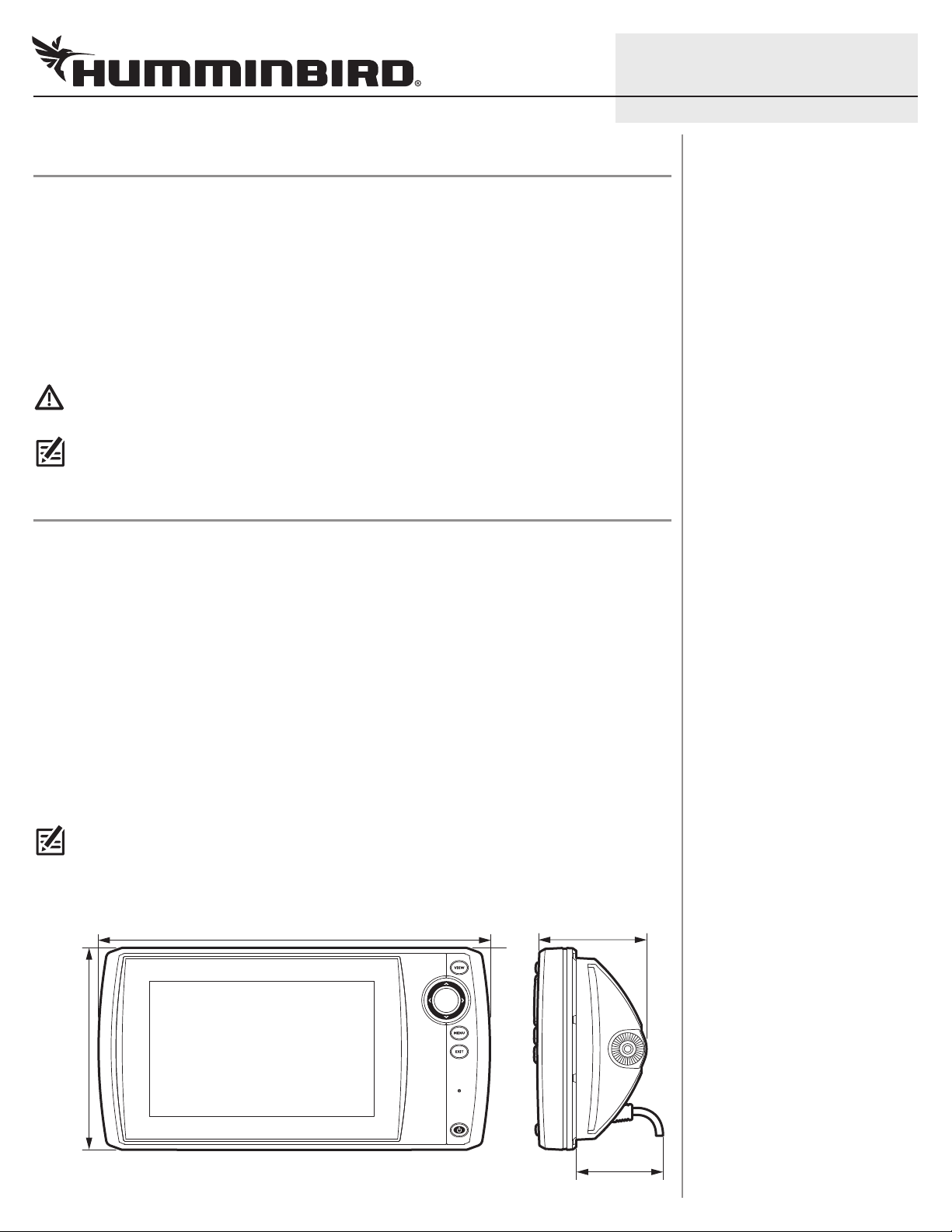
2.17|| (55.12 mm)
10.5 4|| (267.72 mm)
5.44
||
(138.18 mm)
2.97
||
(75.44 m m)
HELIX® 7 Series In-Dash Mounting Installation Guide
Installation Overview
Following are instructions for the in-dash mount installation of the HELIX 7 control head. We encourage you
to read this guide before starting the installation, so you may understand the installation requirements.
Customer Service: If you find that any items are missing from your installation kit, visit our Web site at
humminbird.com or call Humminbird® Customer Service at 1-800-633-1468.
Supplies: In addition to the hardware supplied with your accessory, you will need the gimbal knobs (2) included
with your control head, a drill and various drill bits, a cutting tool for the dashboard material, a 3/8" wrench,
safety glasses and dust mask, and masking tape.
WARNING! Do NOT use power tools to secure the hardware. We encourage you to read the installation instructions
so you may understand the installation requirements.
NOTE: The illustrations in this manual may not look the same as your product, but your unit will function in the same
way.
1. Plan the Mounting Location
Start by locating a suitable, flat area of the dashboard for mounting. Consider the following to find the best
mounting location:
532365-2_B
• Interference: The mounting location must provide adequate distance from electric motors or any
equipment that may cause electronic interference.
• Stability: The mounting area should be protected from waves, shock, vibration, and water.
• Depth: The mounting area should have a depth of 3 inches (7.62 cm) to allow space for the control
head and cables.
• Ventilation: The area beneath the mounting surface should be well-ventilated.
• Accessibility: The location should be easily accessible for all cables to reach the ports on the back of
the control head.
NOTE: If a cable is too short for your application, extension cables are available. For assistance, contact Humminbird
Customer Service at
humminbird.com or call 1-800-633-1468.
HELIX 7 Series Control Head Dimensions
Page 2
2
HELIX® 7 Series In-Dash Mounting Installation Guide
2. Cut the In-Dash Mounting Hole
To in-dash mount the HELIX control head, start by placing the components on the surfaces where you intend
to install them.
1. Review the instructions, measurements, and cutting options indicated on the In-dash Mounting Template.
2. Tape the template to the chosen in-dash mounting location.
3. Using the template, select the cutting method that is best for your boat:
• Drill one entry hole away from the main cut line that is large enough to insert the blade of your
cutting tool.
OR
• Drill a corner hole away from the main cut line using a drill bit that will create a hole as close to a
diameter of .5 inches (12.7 mm) as possible. Repeat for the other three corners as indicated on the
template. Use one of the corner holes as an entry hole, or drill an additional entry hole away from
the main cut line.
4. Carefully begin cutting toward the dotted cut line, and continue cutting to the inside of the line around
the template.
5. Test the Mounting Hole: Install the control head in the mounting hole to test the fit. Make adjustments
to the mounting hole as needed. Remove the template when finished.
532365-2_B
6. Thoroughly clean and deburr the mounting hole.
3. Install the In-Dash Mount Bracket
To install the in-dash mount bracket, you will need the gimbal knobs included with your control head. See
your control head installation guide for more details.
Preparation
1. Place the control head, with the screen facing down, on a towel or cloth on a stable and level surface.
Install the Ratchets
1. Hold the in-dash mount bracket so the arms on the bracket are pointing up.
2. On the inside of the ratchet, locate the ribs (two semicircles) and align them with the openings on the
inside of the bracket arm (see the illustration Installing the Ratchets on the In-Dash Mount Bracket).
With this orientation, install the ratchet on the bracket arm.
3. Repeat: Repeat step 2 to install the second ratchet.
Install the Gimbal Knobs
1. Holding the ratchets in place, lower the bracket (with the bracket arms pointing down) onto the back of the
control head. Align the ratchets on the bracket arms with the openings on the sides of the control head.
NOTE: The in-dash mount bracket is symmetrical. Therefore, it does not require a specific installation orientation.
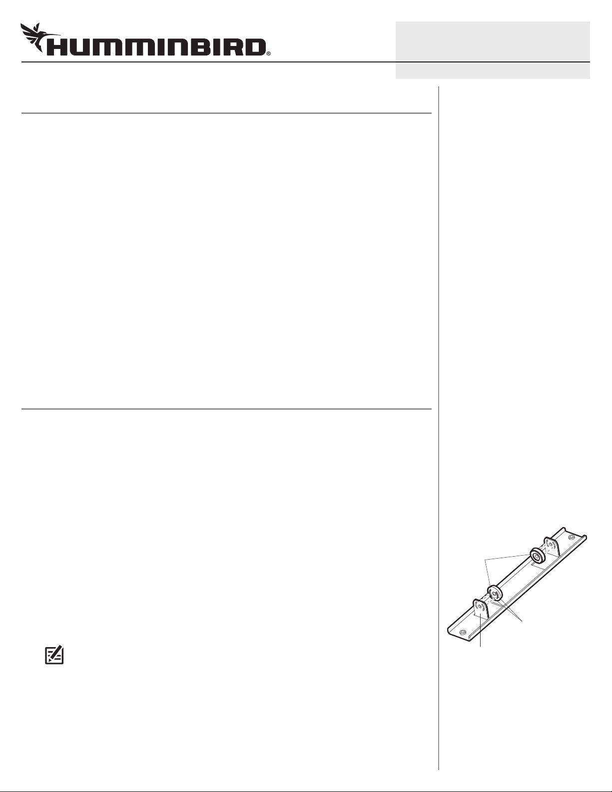
Installing the Ratchets on the
In-Dash Mount Bracket
ratchets
Align the ribs with the
openings on the inside
of the bracket arm.
bracket arm
2. Confirm the bracket is parallel with the face of the control head (see the illustration Installing the
In-Dash Mount Bracket on the Control Head). Thread a gimbal knob into the opening on the control
head and tighten using four to five rotations.
3. Repeat: Repeat step 2 to install the second gimbal knob.
4. Confirm the bracket is still parallel to the face of the control head and hand-tighten both gimbal knobs
to secure the bracket to the control head.
Page 3
3
HELIX® 7 Series In-Dash Mounting Installation Guide
Install the Bolts
1. Place the hardware onto each bolt in the following order: nut and washer. See the illustration Installing
the In-Dash Mount Bracket on the Control Head.
2. Insert the bolts into the threaded bolt holes on the bracket. Hand-tighten the bolts until there is enough
of the bolt exposed on the other side of the bracket to install the end cap. You will fully tighten the bolts
in a later procedure.
3. Install one end cap on the end of each bolt.
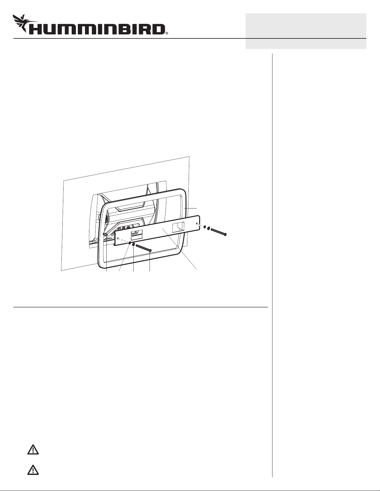
Installing the In-Dash Mount Bracket on the Control Head
bracket reinforcement plate
532365-2_B
Confirm the in-dash mount
end cap
nut boltwasher
bracket is parallel with the
face of the control head.
4. Install the Control Head
1. From the front of the dashboard, with the control head screen facing out, carefully lower the control
head diagonally into the mounting hole. Insert one end of the bracket through the hole first.
2. Adjust the angle so the control head is centered in the mounting hole.
3. Press down lightly on the control head. Confirm the control head is seated flush against the dash. Make
adjustments, as needed.
4. From under the dash, place the bracket reinforcement plate around the back of the control head.
5. Finger-tighten each bolt until the end cap is flush against the bracket reinforcement plate. Then, use a
5/16" socket wrench to hand-tighten the bolts no more than 2 additional turns. Hand-tighten only!
Do NOT over-tighten the bolts. There should be no play or gaps between the unit and the dash. The
bracket should remain straight without bending.
6. Finger-tighten each nut until the nut and washer are flush against the bracket. Fully tighten each nut
using a 3/8" wrench while holding the bolt in place. Do NOT over-tighten the nuts. Hand-tighten only!
WARNING! Do NOT use power tools to secure the hardware.
WARNING! Do NOT over-tighten the bolts. If the bracket is bending or bowing, it is too tight. Over-tightening
the bolts may damage the control head.
Page 4

4
HELIX® 7 Series In-Dash Mounting Installation Guide
5. Route and Connect the Cables
1. See the installation guides included with each hardware
component to install power and other optional equipment.
2. Route all cables (power, transducer, accessories) to the control
head and insert the connectors into the correct ports on the back
of the control head (see the illustration Connecting the Cables).
CAUTION! Do NOT mount the cables where the connectors could
be submerged in water or flooded. If cables are installed in a splashprone area, it may be helpful to apply dielectric grease to the inside
of the connectors to prevent corrosion. Dielectric grease can be
purchased separately from a general hardware or automotive store.
Connecting the Cables
Contact Humminbird
eb site humminbird.com
W
E-mail service@humminbird.com
Telephone 1-800-633-1468
Direct Shipping Humminbird
WARNING! This device should not be used as a navigational aid to
prevent collision, grounding, boat damage, or personal injury. When the boat
is moving, water depth may change too quickly to allow time for you to react.
Always operate the boat at very slow speeds if you suspect shallow water or
submerged objects.
WARNING! Disassembly and repair of this electronic unit should only be
performed by authorized service personnel. Any modification of the serial
number or attempt to repair the original equipment or accessories by
unauthorized individuals will void the warranty.
532365-2_B
Service Department
678 Humminbird Lane
Eufaula, AL 36027 USA
Your control head is ready for on-the-water operation. See your control
head operations manual for further details.
ENVIRONMENTAL COMPLIANCE STATEMENT: It is the intention
of Johnson Outdoors Marine Electronics, Inc. to be a responsible corporate citizen,
operating in compliance with known and applicable environmental regulations, and
a good neighbor in the communities where we make or sell our products.
WEEE DIRECTIVE: EU Directive 2002/96/EC “Waste of Electrical and Electronic
Equipment Directive (WEEE)” impacts most distributors, sellers, and manufacturers of
consumer electronics in the European Union. The WEEE Directive requires the
producer of consumer electronics to take responsibility for the management of waste
from their products to achieve environmentally responsible disposal during the product
life cycle.
WEEE compliance may not be required in your location for electrical & electronic
equipment (EEE), nor may it be required for EEE designed and intended as fixed or
temporary installation in transportation vehicles such as automobiles, aircraft, and
boats. In some European Union member states, these vehicles are considered outside
of the scope of the Directive, and EEE for those applications can be considered
excluded from the WEEE Directive requirement.
This symbol (WEEE wheelie bin) on product indicates the product must
not be disposed of with other household refuse. It must be disposed of
and collected for recycling and recovery of waste EEE. Johnson Outdoors
Marine Electronics, Inc. will mark all EEE products in accordance with the
WEEE Directive. It is our goal to comply in the collection, treatment, recovery, and
environmentally sound disposal of those products; however, these requirements do
vary within European Union member states. For more information about where
you should dispose of your waste equipment for recycling and recovery and/or
your European Union member state requirements, please contact your dealer or
distributor from which your product was purchased.
HELIX® and Humminbird® are registered trademarks of Johnson Outdoors
Marine Electronics, Inc.
© 2018 Johnson Outdoors Marine Electronics, Inc. All rights reserved.
 Loading...