

Page 1
HELIX 5 AND HELIX 7
G2 Series Operations Manual
532509-1EN_A
Page 2
THANK YOU!
hank you for choosing Humminbird®, the #1 name in marine electronics. Humminbird has built its reputation by designing and
T
anufacturing top quality, thoroughly reliable marine equipment. Your Humminbird is designed for trouble-free use in even the
m
arshest marine environment. We encourage you to read this manual carefully in order to get the full benefit from all the features
h
nd applications of your Humminbird product.
a
Contact Humminbird Customer Service at humminbird.com or call 1-800-633-1468.
WARNING! This product contains chemicals known to the State of
California to cause cancer and birth defects or other reproductive
harm.
WARNING! This device should not be used as a navigational aid
to prevent collision, grounding, boat damage, or personal injury.
When the boat is moving, water depth may change too quickly to
allow time for you to react. Always operate the boat at very slow
speeds if you suspect shallow water or submerged objects.
WARNING! The electronic chart in your Humminbird unit is an
aid to navigation designed to facilitate the use of authorized
government charts, not to replace them. Only official
government charts and notices to mariners contain all of the
current information needed for the safety of navigation, and the
captain is responsible for their prudent use.
WARNING! Humminbird is not responsible for the loss of data
files (waypoints, routes, tracks, groups, recordings, etc.) that
may occur due to direct or indirect damage to the unit’s
hardware or software. It is important to back up your control
head’s data files periodically. Data files should also be saved to
your PC before restoring the control head defaults or updating
the software. See the following sections of your Humminbird
manual: Manage Screen Snapshots and Recordings and
Manage your Navigation Data: Import/Export Navigation Data.
WARNING! Disassembly and repair of this electronic unit should
only be performed by authorized service personnel. Any
modification of the serial number or attempt to repair the original
equipment or accessories by unauthorized individuals will void the
warranty.
NOTE: Some features discussed in this manual require a
separate purchase, and some features are only available on
international models. Every effort has been made to clearly
identify those features. Please read the manual carefully in
rder to understand the full capabilities of your model.
o
NOTE: The illustrations in this manual may not look the same as
your product, but your unit will function in a similar way.
NOTE: To purchase accessories for your control head, visit our
Web site at humminbird.com or contact Humminbird Customer
Service at 1-800-633-1468.
NOTE: The procedures and features described in this manual are
subject to change without notice. This manual was written in
English and may have been translated to another language.
Humminbird is not responsible for incorrect translations or
discrepancies between documents.
NOTE: Product specifications and features are subject to change
without notice.
NOTE: Humminbird verifies maximum stated depth in saltwater
conditions, however actual depth performance may vary due to
transducer installation, water type, thermal layers, bottom
composition, and slope.
ROHS STATEMENT: Product designed and intended as a fixed
installation or part of a system in a vessel may be considered beyond
the scope of Directive 2002/95/EC of the European Parliament and of
the Council of 27 January 2003 on the restriction of the use of certain
hazardous substances in electrical and electronic equipment.
WARNING! Do NOT leave the control head microSD card slot
cover open. The slot cover should always be closed to prevent
water damage to the unit.
WARNING! Do not travel at high speed with the unit cover
installed. Remove the unit cover before traveling at speeds
above 20 mph.
ATTENTION INTERNATIONAL CUSTOMERS: Products sold in the U.S.
are not intended for use in the international market. Humminbird
international units provide international features and are designed
to meet country and regional regulations. Languages, maps, time
zones, units of measurement, and warranty are examples of
features that are customized for Humminbird international units
purchased through our authorized international distributors.
To obtain a list of authorized international distributors, please visit
our Web site at humminbird.com or contact Humminbird Customer
Service at (334) 687-6613.
2
Page 3

ENVIRONMENTAL COMPLIANCE STATEMENT: It is the intention of Johnson Outdoors Marine Electronics, Inc. to be a responsible corporate citizen,
operating in compliance with known and applicable environmental regulations, and a good neighbor in the communities where we make or sell
our products.
WEEE DIRECTIVE: EU Directive 2002/96/EC “Waste of Electrical and Electronic Equipment Directive (WEEE)” impacts most distributors, sellers,
and manufacturers of consumer electronics in the European Union. The WEEE Directive requires the producer of consumer electronics to take
esponsibility for the management of waste from their products to achieve environmentally responsible disposal during the product life cycle.
r
WEEE compliance may not be required in your location for electrical & electronic equipment (EEE), nor may it be required for EEE designed and
intended as fixed or temporary installation in transportation vehicles such as automobiles, aircraft, and boats. In some European Union member
states, these vehicles are considered outside of the scope of the Directive, and EEE for those applications can be considered excluded from the
WEEE Directive requirement.
This symbol (WEEE wheelie bin) on product indicates the product must not be disposed of with other household refuse. It must be disposed
of and collected for recycling and recovery of waste EEE. Johnson Outdoors Marine Electronics, Inc. will mark all EEE products in accordance
with the WEEE Directive. It is our goal to comply in the collection, treatment, recovery, and environmentally sound disposal of those
products; however, these requirements do vary within European Union member states. For more information about where you should
ispose of your waste equipment for recycling and recovery and/or your European Union member state requirements, please contact your dealer
d
or distributor from which your product was purchased.
360 Imaging®, AUTOCHART®, AUTOCHART® LIVE, ChartSelect®, Contour XD™, Down Imaging®, DualBeam PLUS™, Fish ID+™, HELIX®, Humminbird®, HumminbirdPC™,
LakeMaster®, Real Time Sonar™, RTS™, RTS Window™, Side Imaging®, SI™, Structure ID™, SwitchFire®, UniMap™, WhiteLine™, X-Press™ Menu, are trademarked by or
registered trademarks of Johnson Outdoors Marine Electronics, Inc.
Adobe, Acrobat, Adobe PDF, and Reader are either registered trademarks or trademarks of Adobe Systems Incorporated in the United States and/or other countries.
Baekmuk Batang, Baekmuk Dotum, Baekmuk Gulim, and Baekmuk Headline are registered trademarks owned by Kim Jeong-Hwan.
microSD and SD are trademarks or registered trademarks of SD-3C, LLC in the United States, other countries or both.
Navionics® Gold, HotMaps™, and HotMaps™ Premium, Navionics® Classic Charts, and Platinum™ Cartography are trademarked by or registered trademarks of Navionics
S.p.A.
© 2016 Johnson Outdoors Marine Electronics, Inc. All rights reserved.
3
Page 4

TABLE OF CONTENTS
Warnings 2
Introduction 7
sing Humminbird Manuals on your Mobile Device or PC 8
U
etting Started 10
G
HELIX Control Head 18
Menu System Overview 22
Open an X-Press Menu . . . . . . . . . . . . . . . . . . . . . . . . . . . . . . . . . . .22
Open the Main Menu . . . . . . . . . . . . . . . . . . . . . . . . . . . . . . . . . . . . .22
Select a Menu . . . . . . . . . . . . . . . . . . . . . . . . . . . . . . . . . . . . . . . . . .23
Change a Menu Setting . . . . . . . . . . . . . . . . . . . . . . . . . . . . . . . . . .23
Tips for Using the Menu System . . . . . . . . . . . . . . . . . . . . . . . . . .24
Change the User Mode (Normal or Advanced) . . . . . . . . . . . . . .25
Close the Menu System . . . . . . . . . . . . . . . . . . . . . . . . . . . . . . . . . .25
Views 26
Display a View . . . . . . . . . . . . . . . . . . . . . . . . . . . . . . . . . . . . . . . . . . .26
Show your Favorite Views . . . . . . . . . . . . . . . . . . . . . . . . . . . . . . . .27
Display Digital Readouts . . . . . . . . . . . . . . . . . . . . . . . . . . . . . . . . .28
Combo Views . . . . . . . . . . . . . . . . . . . . . . . . . . . . . . . . . . . . . . . . . . .32
Sonar Overview (Sonar, DI, SI, CHIRP) 33
Display a Down Imaging View On-Screen 77
Understand the Down Imaging View . . . . . . . . . . . . . . . . . . . . . . .78
ustomize the Down Imaging View . . . . . . . . . . . . . . . . . . . . . . . .79
C
Adjust Settings While you Fish . . . . . . . . . . . . . . . . . . . . . . . . . . . .82
Review Down Imaging History and Zoom In/Zoom Out . . . . . . .86
Navigation in Down Imaging Views . . . . . . . . . . . . . . . . . . . . . . . .88
Display a Side Imaging View On-Screen 90
Understand the Side Imaging View . . . . . . . . . . . . . . . . . . . . . . . .91
Customize the Side Imaging View . . . . . . . . . . . . . . . . . . . . . . . . .93
Adjust Settings While you Fish . . . . . . . . . . . . . . . . . . . . . . . . . . . .96
Review Side Imaging History and Zoom In/Out . . . . . . . . . . . .102
Navigation in Side Imaging Views . . . . . . . . . . . . . . . . . . . . . . . .104
Manage Screen Snapshots and Recordings 106
Chart Overview 114
Display a Chart View On-Screen . . . . . . . . . . . . . . . . . . . . . . . . .115
Select a Map Source . . . . . . . . . . . . . . . . . . . . . . . . . . . . . . . . . . .116
Customize the Bird’s Eye View . . . . . . . . . . . . . . . . . . . . . . . . . . .121
Customize the Chart Instrument View . . . . . . . . . . . . . . . . . . . .122
Customize the Chart View . . . . . . . . . . . . . . . . . . . . . . . . . . . . . . .123
Display Humminbird LakeMaster
Contour Lines and Depth Ranges . . . . . . . . . . . . . . . . . . . . . .127
Change the Chart Orientation and Motion Mode . . . . . . . . . . .129
Set up Sonar (Sonar, DI, SI, CHIRP) 36
Display a Sonar View On-Screen 42
Understand the Sonar Views . . . . . . . . . . . . . . . . . . . . . . . . . . . . . .44
Customize the Sonar View . . . . . . . . . . . . . . . . . . . . . . . . . . . . . . . .45
Adjust Sonar Display Settings . . . . . . . . . . . . . . . . . . . . . . . . . . . .50
Adjust Settings While you Fish . . . . . . . . . . . . . . . . . . . . . . . . . . . .54
Compare Sonar Beams (Split Sonar View) . . . . . . . . . . . . . . . . .59
Review Sonar History . . . . . . . . . . . . . . . . . . . . . . . . . . . . . . . . . . . .60
Zoom In/Zoom Out . . . . . . . . . . . . . . . . . . . . . . . . . . . . . . . . . . . . . .61
Navigation in Sonar Views . . . . . . . . . . . . . . . . . . . . . . . . . . . . . . . .65
Display the Circular Flasher View On-Screen 68
Understand the Circular Flasher View . . . . . . . . . . . . . . . . . . . . . .69
Adjust Settings while you Fish . . . . . . . . . . . . . . . . . . . . . . . . . . . .70
Move the Depth Cursor . . . . . . . . . . . . . . . . . . . . . . . . . . . . . . . . . . .74
Zoom In/Out in Circular Flasher View . . . . . . . . . . . . . . . . . . . . . .75
Navigation Overview 131
Navigation Alarms Overview . . . . . . . . . . . . . . . . . . . . . . . . . . . . .133
Man Overboard (MOB) Navigation . . . . . . . . . . . . . . . . . . . . . . . .134
Waypoints 136
Routes 145
Tracks 150
Search 153
Manage your Navigation Data 155
Manage Waypoints . . . . . . . . . . . . . . . . . . . . . . . . . . . . . . . . . . . . .158
Manage Routes . . . . . . . . . . . . . . . . . . . . . . . . . . . . . . . . . . . . . . . .162
Manage Tracks . . . . . . . . . . . . . . . . . . . . . . . . . . . . . . . . . . . . . . . . .169
Manage Groups . . . . . . . . . . . . . . . . . . . . . . . . . . . . . . . . . . . . . . . .171
Search and Organize . . . . . . . . . . . . . . . . . . . . . . . . . . . . . . . . . . .175
Import/Export Navigation Data . . . . . . . . . . . . . . . . . . . . . . . . . .177
Delete All Navigation Data and Reset . . . . . . . . . . . . . . . . . . . . .177
4
Page 5

TABLE OF CONTENTS
AutoChart Live Overview 178
Plan Your Map . . . . . . . . . . . . . . . . . . . . . . . . . . . . . . . . . . . . . . . . .178
Prepare the Control Head for Mapping . . . . . . . . . . . . . . . . . . . .179
ecord your Custom Map . . . . . . . . . . . . . . . . . . . . . . . . . . . . . . .182
R
Stop Recording . . . . . . . . . . . . . . . . . . . . . . . . . . . . . . . . . . . . . . . .184
Correct Data . . . . . . . . . . . . . . . . . . . . . . . . . . . . . . . . . . . . . . . . . . .184
Display/Hide your Custom Map . . . . . . . . . . . . . . . . . . . . . . . . . .185
Adjust the Map Display Settings . . . . . . . . . . . . . . . . . . . . . . . . .186
Manage your Control Head 190
Update Software 195
Maintenance 196
Troubleshooting 197
Specifications 199
Contact Humminbird 215
5
Page 6

6
Page 7
INTRODUCTION
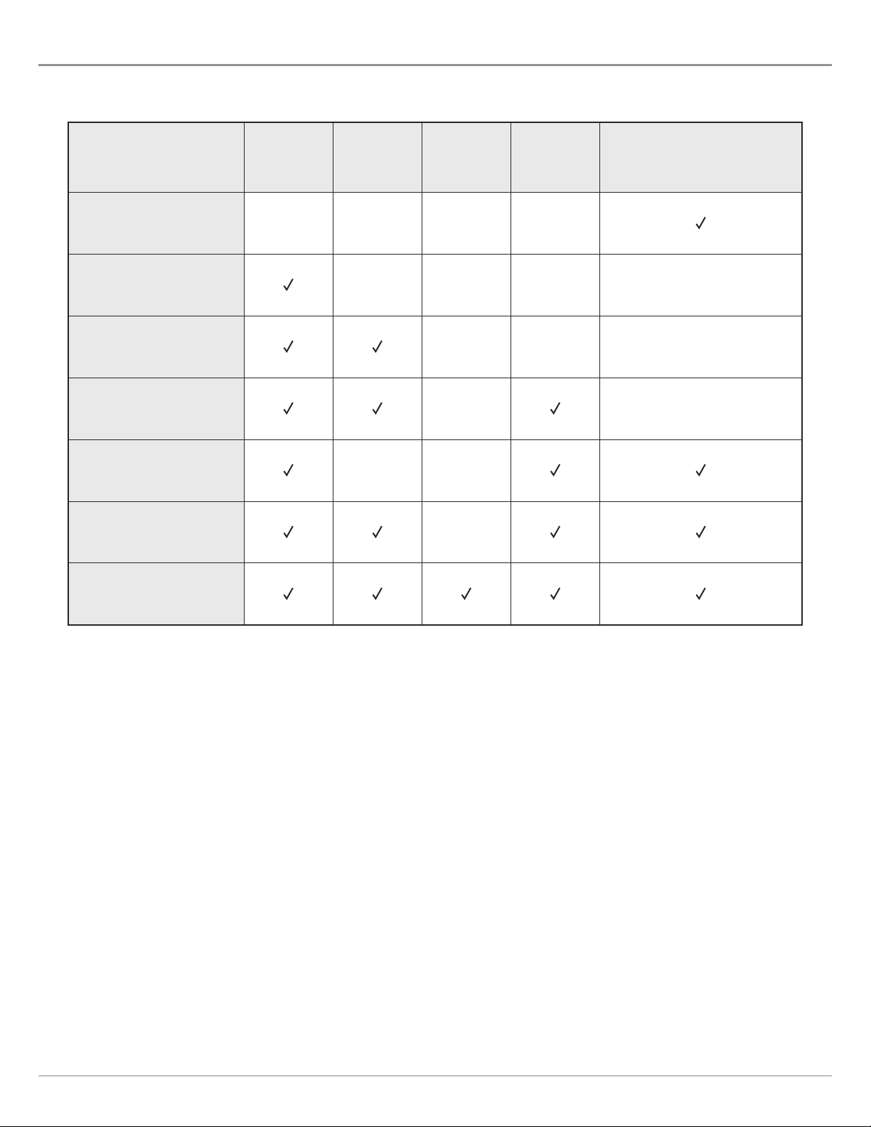
he instructions in this manual describe the HELIX G2 Series control head operations. Review the following table to understand the
T
eatures that apply to your control head.
f
Model
HELIX GPS G2
HELIX SONAR G2
HELIX DI G2
HELIX CHIRP DI G2
HELIX CHIRP GPS G2
HELIX CHIRP DI GPS G2
2D
Sonar
Down
Imaging
Side
Imaging
CHIRP
(Charts and Navigation)
GPS
External GPS, trackplotting
(separate purchase required)
External GPS, trackplotting
(separate purchase required)
External GPS, trackplotting
(separate purchase required)
HELIX CHIRP SI GPS G2
Accessories: For the latest list of accessories that are compatible with your control head, visit our Web site at humminbird.com.
Register and Update: It is important to register your products and keep your software up to date. Visit our Web site at
humminbird.com to set up an account, update control head and accessory software, and purchase additional equipment. Also, see
Update Software in this manual for more information.
7
Introduction
Page 8

USING HUMMINBIRD MANUALS ON YOUR MOBILE DEVICE OR PC
The Humminbird manuals for your control head and accessories can be downloaded to your mobile device or PC. If you prefer to use
a hard copy for reference, this manual may be printed.
Download the Manual to your Mobile Device
1. Download the free Adobe Acrobat Reader app to your mobile device.
2. Go to our Web site at humminbird.com, and click Support > Product Manuals.
3. Select the PDF for your control head model or accessory, and save it to your device.
4. Open the Adobe Acrobat Reader app.
5. Open the Humminbird manual.
Download the Manual to your PC
1. Download the free Adobe Acrobat Reader software from http://get.adobe.com/reader/, and install it on your PC.
2. Go to our Web site at humminbird.com, and click Support > Product Manuals.
3. Select the PDF for your control head model or accessory, and save it to your device.
4. Open Adobe Acrobat Reader.
5. Open the Humminbird manual.
Jump to a Section: Click a section name in the Bookmarks panel. Bookmarks can be expanded and collapsed by clicking on
the plus (+) or minus (-) icons.
Search for Words or Phrases: Press and hold the Ctrl F keys on your PC keyboard. Type the word(s) into the text box.
Print: If you prefer to use a hard copy for reference, this manual may be printed.
Introduction
8
Page 9

Using the Manual
bookmarks
panel
search for
key words
(Ctrl + F)
9
Introduction
Page 10

GETTING STARTED
The procedures in this section describe how to get started with your control head. Some of the settings in this section are a one-
ime set up, and other settings (such as checking the GPS reception) you will use each time you hit the water.
t
Power On
Follow the instructions below to power on your Humminbird control head.
1. Press the POWER key.
2. When the Title screen is displayed, press the MENU key.
Title Screen
Getting Started
Press the MENU key
10
Page 11

. Select Normal. Press the RIGHT Cursor key.
3
Normal mode is required for on-the-water operation. If a functioning transducer is connected
Normal
to the control head, Normal will be selected automatically, and your control head can be used
n the water.
o
To learn how to use your control head, select Simulator. You can save menu settings and
Simulator
navigation data in Simulator mode (see Chart Overview and Navigation Overview for more
information).
To view system information for software version, GPS reception, and accessory connections,
System Status
select System Status. See Check Accessory Connections and Check GPS Reception for more
information.
NOTE: If you wait too long to select a start-up option, the system will start the mode that is already highlighted. If your control head
goes into Demonstration mode, please note that menu settings cannot be saved in this mode (see Manage your Control Head).
Starting Normal Mode for on-the-water Operations
Press the
RIGHT Cursor key
11
Getting Started
Page 12
Quick Setup
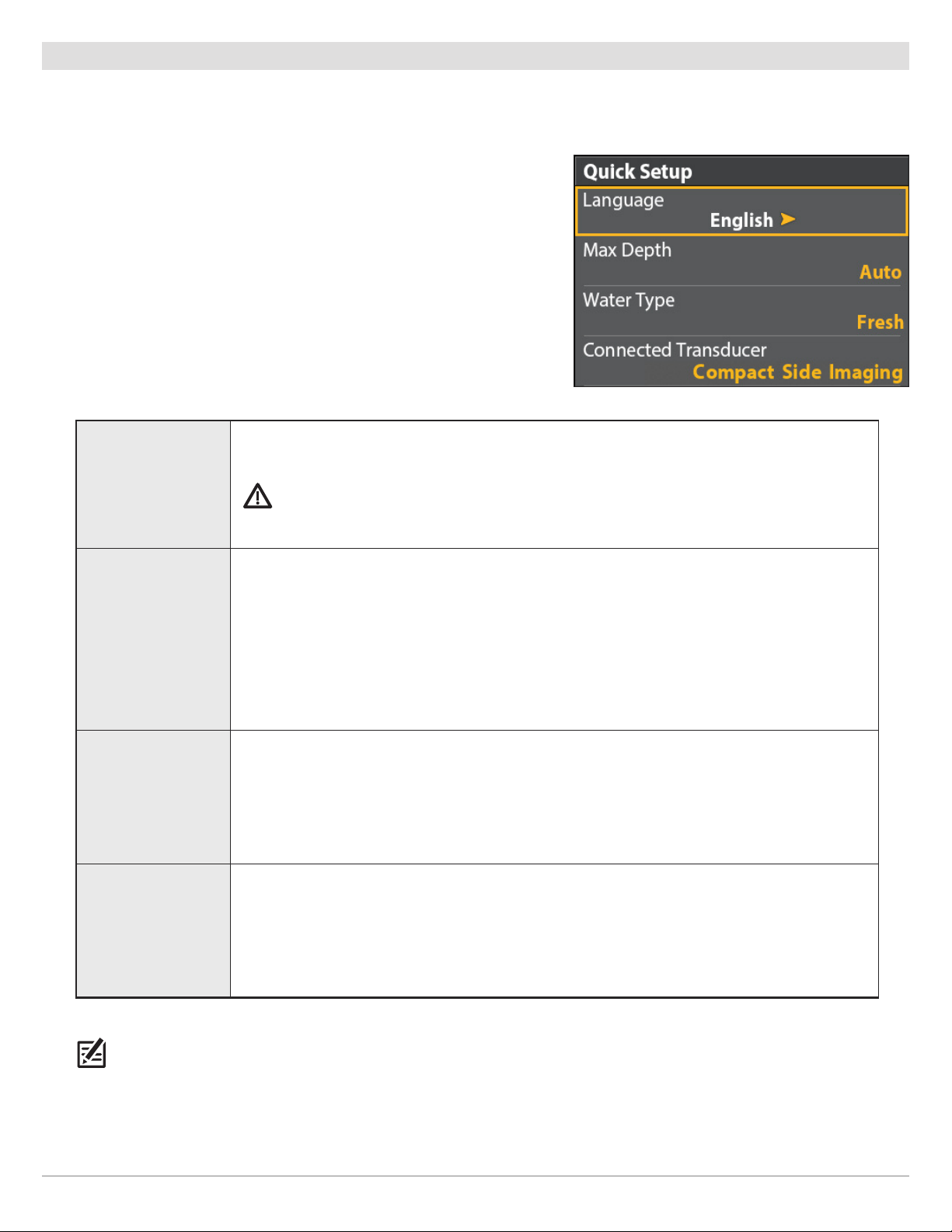
If this is the first time the unit has been powered on (after installation or after restoring defaults), the Quick Setup menu will display.
Set up the Control Head
1. Use the Cursor Control key to change the settings.
2. Close: Press the EXIT key.
The available languages are determined by your Humminbird model.
Language
Max Depth
WARNING! Do NOT enable Asian Mode if you do not require Asian languages. Before you select
Asian Mode, contact Customer Service for important information.
Set the maximum depth of the body of water. When Max Depth is set to Auto, the control head
will acquire bottom readings as needed (within the capabilities of the unit). When Max Depth
is set to match your water maximum depth, the control head will not attempt to acquire sonar
data below that depth, so more detail will be shown on the display.
Quick Setup Menu
Side Imaging units default to the Side Imaging range setting if the SI Range is set deeper than
the Max Depth. See the Side Imaging section for more information.
Water Type affects the accuracy of deep water depth readings and configures the control head
for operation in fresh or salt water.
Water Type
In salt water, you can also choose the shallow or deep setting. If the depth is more than 330 ft
(100 m), select Salt (deep).
The control head will automatically select the transducer that was included with your control
Connected
Transducer
head. If your model is compatible with an accessory transducer, and it is connected to the
control head, select the transducer in the system so the beams are activated and the related
views are added to the control head.
NOTE: To change the Max Depth, Water Type, and the Connected Transducer after the initial Setup, see Set up Sonar.
Getting Started
12
Page 13
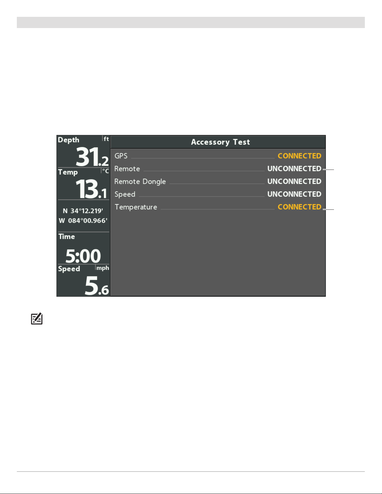
Check Accessory Connections
If you’ve connected other separate-purchase equipment to the control head, such as AIS, Compass/Heading Sensor, and more,
use these instructions to confirm the equipment is detected and communicating with the control head.
1. Press and hold the VIEW key.
2. Select System > Accessory Test.
Confirm all accessories are listed as Connected. If you have a temp/speed wheel, the wheel must move for it to be detected.
Unconnected: If an accessory is listed as Unconnected, check the cable and power connections to confirm they are secure and
powered on. Review the installation guide that was included with your accessory to confirm it is installed correctly.
Confirming Accessories are Detected
unconnected
(not detected
by the control
head)
connected
NOTE: The menus for installed accessories are typically included in the Accessory tab in the Main Menu. See your accessory guide
for details. For the latest list of accessories that are compatible with your control head, visit our Web site at humminbird.com.
13
Getting Started
Page 14
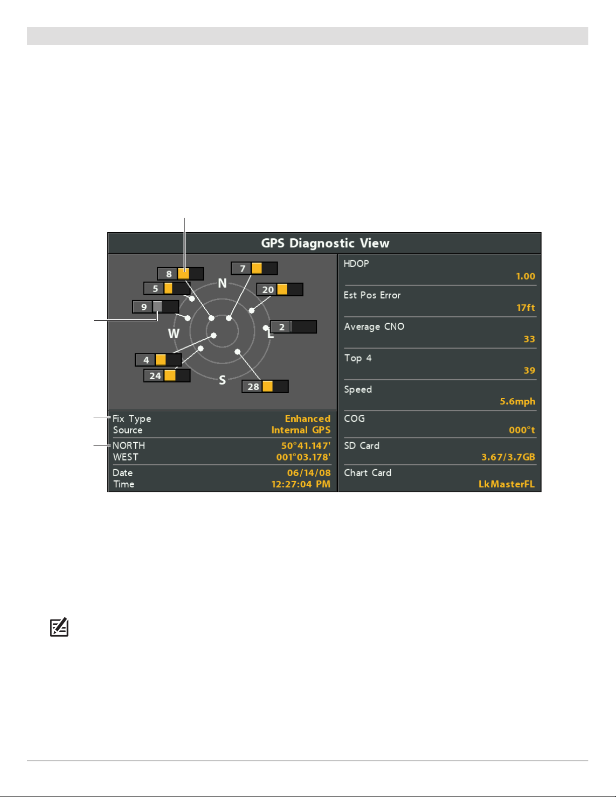
Check GPS Reception
If your control head includes internal GPS, or if it is connected to an External GPS receiver, use the instructions in this section to
confirm the control head has GPS reception.
1. Press and hold the VIEW key.
2. Select System > GPS Diagnostic View.
Confirm GPS Fix Type is shown as Enhanced or 3D.
Confirm that the latitude/longitude position readout is displayed.
Reviewing GPS Reception
active satellite signal strength (yellow)
monitored satellite
signal strength
(gray)
fix type shown as
enhanced
latitude/longitude
position
GPS Reception: The sky chart displays the satellite number and signal strength bar.
GPS Fix Type: reported as No Fix, 2D Fix, 3D Fix, or Enhanced. An Enhanced Fix has been augmented using information from
WAAS, EGNOS, or MSAS.
HDOP (the Horizontal Dilution of Precision): a GPS system parameter which depends on the current satellite configuration.
HDOP is used to calculate the Estimated Position Error.
NOTE: To manually change your GPS source, change the output frequency, or turn on GLONASS, see Manage your Control Head.
Getting Started
14
Page 15
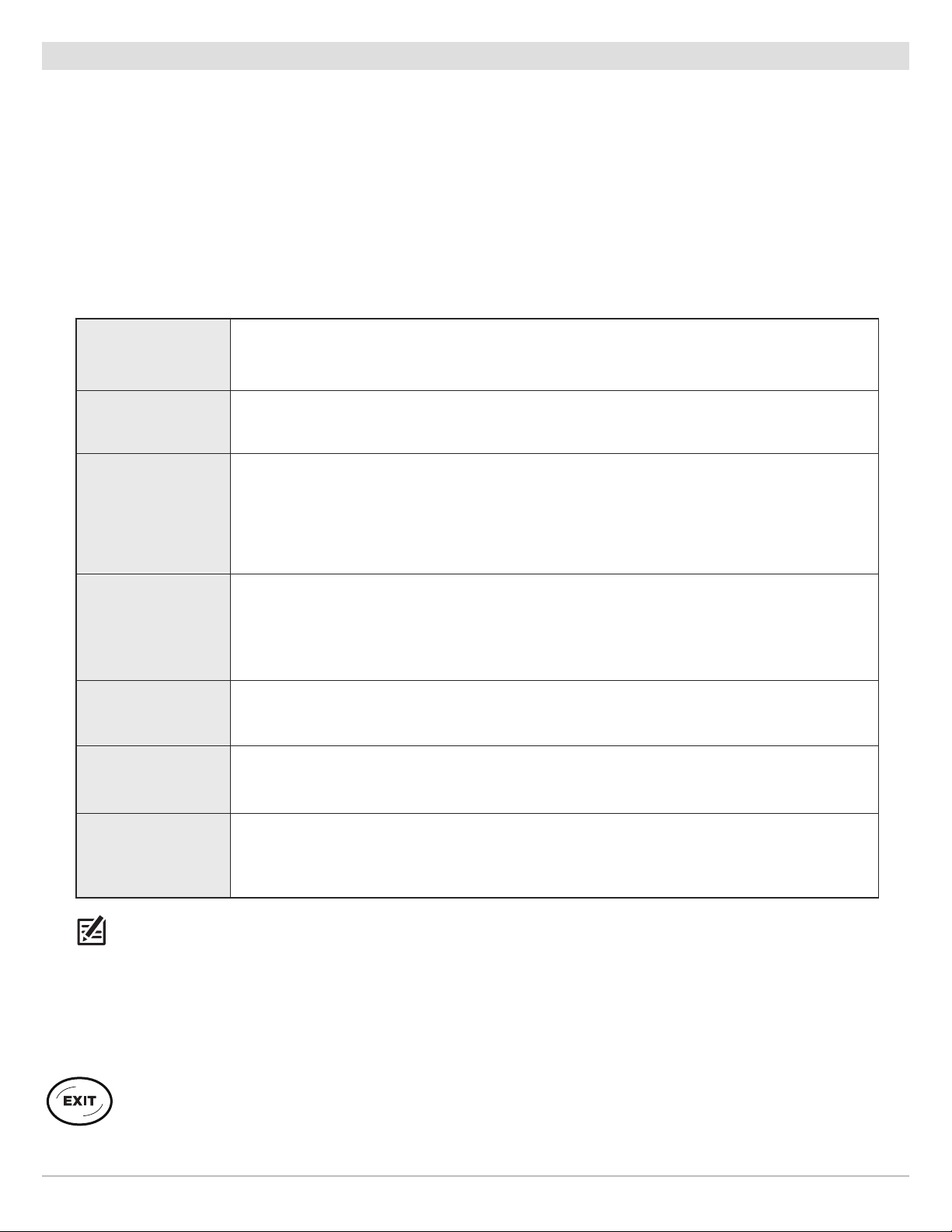
Set Alarms
When an alarm is turned on, an alert will sound or display on the control head to indicate the threshold has been exceeded.
Turn on Alarms and Adjust Settings
1. Main Menu: Press the MENU key twice.
OR
To open the Main Menu from a System View, press the MENU key once.
2. Select the Alarms tab.
3. Select an alarm menu. Press the RIGHT or LEFT Cursor keys to adjust the threshold.
Depth Alarm
Fish ID Alarm
Low Battery Alarm
Temp. Alarm
Off Course Alarm
Arrival Alarm
The alarm will be triggered when the depth becomes equal to or less than the menu setting.
Transducer required.
The alarm will be triggered when a fish is detected based on the menu setting. See Adjust Sonar
Display Settings for more information.
The alarm will be triggered when the input battery voltage is equal to or less than the menu
setting. The battery must be connected to the control head. Set the alarm to a level that will
alert you when the battery is low but at a level that is high enough to start the engine and run
essential electronics. See your control head installation guide for more information.
The alarm will be triggered when the water temperature detected by the control head is equal
to the temp alarm setting. Input from the built-in transducer temperature sensor or a
temperature accessory is required.
Sets how far the boat can move off course during navigation before an alarm will be triggered.
GPS required. See Navigation Overview for more information.
Sets how close the boat must be to the destination waypoint before the alarm will be triggered.
GPS required. See Navigation Overview for more information.
Drift Alarm
NOTE: The available alarms are determined by the connected equipment, so your control head may provide more or less options
than the information shown here. If there are accessories installed, review the accessory guide for alarm information.
4. Close: Press the EXIT key twice.
Sets how far the boat can move from its anchored position outside the drift alarm perimeter
before an alarm will be triggered. GPS required. See Navigation Overview for more information.
Exit an Alarm
If an alarm is triggered during control head operation, you can close it or silence it using these instructions.
1. Press any key on the control head.
15
Getting Started
Page 16

Reset the Triplog
he Triplog includes the timer for elapsed time, distance traveled since last reset, and average speed. Use the following instructions
T
to reset the triplog. To display the Triplog as a digital readout, see Views: Display Digital Readouts.
1. Main Menu: Press the MENU key twice.
2. Select the Setup tab.
3. Select Triplog Reset.
4. Press the RIGHT Cursor key.
5. Follow the on-screen prompts.
Turn on/off Sound
Use the instructions in this section to choose the category of sounds you want to hear from your control head.
1. Main Menu: Press the MENU key twice.
2. Select the Setup tab.
3. Select Sound Control.
4. Select All Sounds or Alarms only.
To receive a sound alert from an alarm, Sound Control must be set to All Sounds or Alarms Only.
Change the Alarm Tone: Select the Alarms tab > Alarm Tone.
Change the User Mode
The User Mode determines how many menu options are displayed in the menu system. Select Normal to see fewer menu options
that are used more often. Select Advanced to see all the menu options available in the menu system.
Instructions in this manual marked with Main Menu (Advanced User Mode) indicate that the menu system User Mode must be set
to Advanced for the selected menu to be shown. If you do not see the menu in the system, change the User Mode to Advanced. See
Menu System Overview for details.
1. Main Menu: Press the MENU key twice.
2. Select the Setup tab.
3. Select User Mode.
4. Select Normal or Advanced.
Set up Sonar
If you’ve installed an accessory transducer, or to refine your sonar settings, see Set up Sonar for details.
Set up Chart Preferences
If you’ve installed a microSD map card, see Chart Overview to set up the map source.
Getting Started
16
Page 17

Change Units of Measurement
Use the instructions in this section to change the units of measurement format. You can also change the time and date format,
language, and installation offsets from this menu. See Manage your Control Head for more information.
1. Main Menu: Press the MENU key twice.
2. Select the Setup tab.
3. Select Units - Depth, Units - Distance, etc., and select each unit setting as needed.
4. Close: Press the EXIT key.
Adjust the Backlight
1. Press the POWER key.
2. Select Light.
3. Adjust the Backlight setting from Dim to 10 (brightest).
Start Standby Mode
To conserve power while the control head is not in-use, start Standby mode.
1. Press the POWER key.
2. Select Standby.
3. Press the RIGHT Cursor key.
4. Turn off: Press the POWER key.
Power Off
Use the following instructions to power off your control head. You should save the current track before powering off, and your control
head should always be turned off using the POWER key.
Save the Current Track
1. Chart X-Press Menu: With a Chart View displayed on-screen, press the MENU key once.
2. Select Save Current Track.
3. Press the RIGHT Cursor key.
Power Off
1. Press and hold the POWER key.
17
Getting Started
Page 18

HELIX CONTROL HEAD
VIEW
MENU
EXIT
HELIX 5 SONAR G2 and HELIX 5 DI G2
HELIX 7 G2 Series Models with GPS
The Control Head
18
Page 19

Control Head Keys
he available keys are determined by your control head model.
T
Your control head might not include all the keys shown in this
section.
MARK KEY
Press the MARK key to save a waypoint at the boat
osition. If the cursor is active, press the MARK key
p
twice to save a waypoint at the cursor position. See
Navigation Overview for details.
ZOOM IN (+)/ZOOM OUT (–) KEYS
Press the ZOOM keys to change the scale of the view.
For a closer view, press the ZOOM IN (+) key. For a
wider view, press the ZOOM OUT (-) key. You can also
magnify the cursor selection. You can also press
these keys to adjust the sensitivity in sonar views
(Sonar, DI, SI).
VIEW KEY
Press and hold the VIEW key to open the Views
X-Press menu, or press the VIEW key repeatedly until
the view you want to use is displayed on the screen.
Press the EXIT key to display the previous view. See
Views for details.
CHECK/INFO KEY
In the Chart View, press the CHECK/INFO key to see
information about the cursor position or about
objects located near the cursor position. If the cursor
is not active, the Chart Info submenu will open. See
Navigation Overview for details.
If a microSD card is installed, press and hold this key
to save a Screen Snapshot. See Manage Screen
Snapshots and Recordings for details.
MENU KEY
To open the X-Press Menu for the on-screen view and
operation mode, press the MENU key once. To open
the Main Menu, press the MENU key twice. See Menu
System Overview for details.
GO TO/MAN OVERBOARD (MOB) KEY
With an active cursor, press the GOTO key twice to
create a waypoint and start navigation towards that
waypoint. If the cursor is not active, press the GOTO
key, and choose from the saved navigation data.
To start Man Overboard navigation, press and hold the
GOTO key. See Navigation Overview and Man
Overboard (MOB) Navigation for details.
EXIT KEY
In Sonar Views, press this key once to switch
frequencies (if available). See each sonar section for
details.
CURSOR CONTROL KEY
(LEFT, RIGHT, UP, or DOWN Cursor keys)
Press the arrows on the Cursor Control key
to move through the menu system, select
menus, and change or activate menu
settings. See Menu System Overview for
details.
Also, press any arrow on the Cursor Control
key to move the cursor on the view.
To move the cursor diagonally, press in
between the arrows.
Press the EXIT key to close a menu, close a dialog box,
turn off an alarm, or exit Cursor mode.
Also, press the EXIT key to scroll through the View
Rotation in reverse order. See Views for details.
POWER KEY
Press the POWER key to power on the control head.
To power off, press and hold the POWER key.
During operation, press the POWER key. The backlight
can be adjusted from this menu. You can also turn
on/off Sonar, change the view background color, and
start Standby mode.
19
The Control Head
Page 20

microSD Card Slot
he microSD card slot on your control head is compatible with a microSD card (separate purchase required) to update software,
T
add detailed charts to your control head, import/export navigation data, and save sonar recordings and screen snapshots.
Software Updates: For details, see Update Software.
Add Maps: see Chart Overview.
Import/Export Navigation data: See Manage your Navigation Data.
Sonar Recordings and Screen Snapshots: See Manage Screen Snapshots and Recordings.
CAUTION! Before the control head software is updated or restored to system defaults, export your navigation data (see Update
Software).
Insert a microSD Card
1. Remove the microSD card slot cover.
2. Position the microSD card so that the label faces the front of the control head and the card notches face down.
3. Insert the card into the slot until it clicks into place.
4. Replace the slot cover so it is secure.
5. To Remove: Press the card into the slot and then release it. The card will eject. Pull the card carefully from the slot.
NOTE: Do not leave the card slot cover open. The slot cover should always be closed to prevent water damage to the unit.
The Control Head
20
Page 21

Removing the Card Slot Cover
Installing a microSD Card (magnified view)
notch facing down
21
The Control Head
Page 22

MENU SYSTEM OVERVIEW
xx11
he menu system provides menu options that are determined by the operations mode, on-screen view, and connected accessories.
T
Open an X-Press Menu
The X-Press Menu displays menus that are related to the on-screen view and the operations mode (such as navigation). In this
illustration, the Sonar X-Press Menu is displayed because the Sonar View is displayed on the screen.
pening the Sonar X-Press Menu
Open the X-Press Menu
1. Press the VIEW key repeatedly until the view you want
is displayed on-screen.
2. Press the MENU key once.
O
Open the Main Menu
The main menu is divided into tabbed categories (Alarms, Sonar,
Navigation, Chart, Humminbird Chart, Setup, Views, and Accessories).
The available tabs and menus are determined by your model and the
connected accessories.
Open the Main Menu
1. Press the MENU key twice.
Opening the Main Menu
Menu System Overview
22
Page 23

Select a Menu
se the Cursor Control key to select a menu in the Main Menu or X-Press Menu.
U
Select a Tab (Main Menu) Select a Menu
1. Press the RIGHT or LEFT Cursor keys. 1. Press the DOWN or UP Cursor keys.
Select a Tab
Select a Menu
Change a Menu Setting
Use the Cursor Control key to change menu settings or start an action. When you change a menu setting, the view will update immediately.
Adjust a Menu Setting
1. Press the RIGHT or LEFT Cursor keys.
Change a Menu Setting
23
Menu System Overview
Page 24

tart an Action/Open a Submenu
S
1. If a menu has a right arrow on it, press the RIGHT Cursor key to start the
action or open the submenu.
Tips for Using the Menu System
You can move through the menu system quickly using the following tips.
Jump to the Bottom of the Tab
Start an Action or Open a Submenu
Jump to the Top of the Tab
Menu System Overview
See More Menus
24
Page 25

Change the User Mode (Normal or Advanced)
he User Mode determines how many menus are shown in the menu system. Select Normal to see fewer menus that are used more
T
often. Select Advanced to see all the menus available in the menu system.
Main Menu (Advanced User Mode): Instructions in this manual marked with Main Menu (Advanced User Mode) indicate that the
menu system User Mode must be set to Advanced for the selected menu to be shown. If you do not see the menu in the system,
change the User Mode to Advanced.
Change the User Mode
1. Main Menu: Press the MENU key twice.
2. Select the Setup tab.
3. Select User Mode.
4. Select Normal or Advanced.
Main Menu: Sonar Tab
(User Mode set to Normal)
Main Menu: Sonar Tab
(User Mode set to Advanced)
Close the Menu System
Use the EXIT key to go back through the menu system or close the menu system.
Back: Press the EXIT key to close the current menu and go back one level in the menu system.
Close: Press the EXIT key repeatedly until the menu system is closed.
25
Menu System Overview
Page 26
VIEWS
he HELIX control head has many options to display data on-screen, and the data can be displayed in a variety of ways. There are
T
lso several ways to quickly display a view on-screen.
a
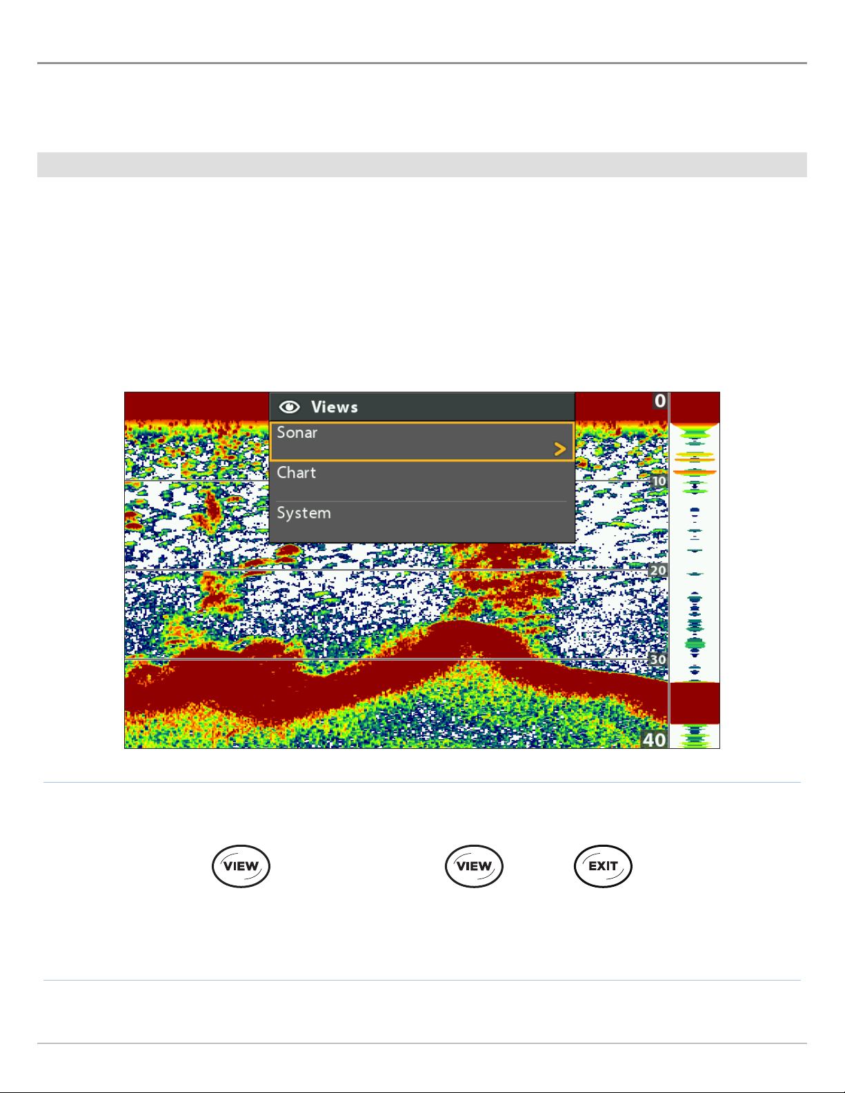
Display a View
The available views on your control head are determined by the model you’ve purchased and the connected transducer.
Display a View from the Views X-Press Menu
1. Press and hold the VIEW key.
2. Select a view category. Press the RIGHT Cursor key.
3. Select a view. Press the RIGHT Cursor key.
Selecting a View to Display on the Screen
Views
Press and Hold to Open
the Views X-Press Menu
OR
Forward: Press to go
to the Next View
26
Back: Press to go to
the Previous View
Page 27

isplay the Next/Previous View
D
Next View: Press the VIEW key repeatedly until the view you want is displayed on-screen.
Previous View: Press the EXIT key repeatedly until the view you want is displayed on-screen.
Show your Favorite Views
You can display or hide any view so that each time you press the VIEW key, only your favorite views are displayed on the screen.
Show/Hide a View
1. Main Menu: Press the MENU key twice.
2. Select the Views tab.
3. Select a view.
4. Select Hidden or Visible.
Hide Sonar Views
If you’re using your control head for GPS/Navigation functions only, use these
instructions to hide all sonar views from the view rotation. This setting also
deactivates sonar.
1. Press the POWER key.
2. Select Sonar.
3. Select Off.
NOTE: You can also turn on/off Sonar from the Main Menu > Setup tab > Sonar.
Main Menu: Views Tab
27
Views
Page 28
Display Digital Readouts
igital Readout data can be displayed as an overlay, or it can be displayed in data boxes on the views. You can also choose which
D
digital readouts you want to display. The format and readouts you choose will be applied to all views.
Accessories: The available digital readouts are determined by the installed equipment, so if you connect accessories, additional
readouts will be available.
Format: You can change the digital readout format from the Setup Tab. See Manage your Control Head: Change Digital Readout
Formats for details.
Select the Digital Readout Type
Use the instructions in this section to display digital readouts in boxes or as overlays. You can also choose to hide the digital readouts
completely.
1. Main Menu: Press the MENU key twice. Select the Setup tab.
2. Select Digital Readouts.
3. Select one of the following options:
Digital Readouts are displayed in boxes on the view. See the illustration Digital Readouts with
Boxes
Boxes Selected. You can customize which digital readouts are displayed (see Customize
Digital Readouts).
Overlay
Off
The digital readouts are displayed as an overlay on the view. See the illustrations Digital
Readouts with Overlay Selected. These digital readouts are fixed and cannot be changed.
The digital readouts will be hidden completely. To hide individual digital readouts instead of all,
see Customize Digital Readouts.
Show/Hide Digital Readouts on the Side Imaging View
If you have Digital Readouts set to Boxes on all views, you can hide the digital readout boxes on the Side Imaging View exclusively.
1. Main Menu: Press the MENU key twice. Select the Sonar tab.
2. Select SI Readouts.
3. Select On (show) or Off (hide).
Views
28
Page 29
speed
temperature
depth
Digital Readouts with Overlay Selected (Sonar View)
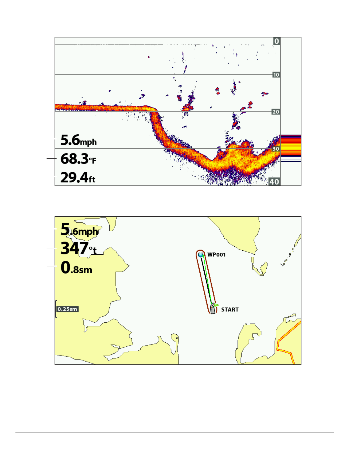
speed
Course Over
Ground (COG)
Distance to Go
(DTG)
Digital Readouts with Overlay Selected (Chart View)
29
Views
Page 30

ustomize Digital Readouts
C
If you have Digital Readouts set to Boxes, you can select the data that will be displayed in each box. Use the Select Readouts menu
to set your standard digital readouts. Use the Select Nav Readouts menu to set the digital readouts that will be displayed during
navigation.
1. Main Menu (Advanced User Mode): Press the MENU key twice. Select the Setup tab.
2. Select Select Readouts or Select Nav Readouts. Press the RIGHT Cursor key.
3. Select a readout window (Readout 1, 2, 3, etc.).
4. Select a digital readout.
Hide: To hide a readout window, select Off.
Digital Readouts with Boxes Selected (Down/Sonar Combo View)
readout 1
readout 2
readout 3
readout 4
readout 5
(off = blank)
select
readouts
menu
readout 5
turned off
digits format set
to large tenths
Views
30
Page 31

nderstand Digital Readouts
U
The following table displays the digital readouts that are available in the Select Readouts menu or the Select Nav Readouts menu.
The available digital readouts are determined by the installed equipment.
Label Name Description
Bearing Bearing
COG
Depth Depth
DTG
ETA
Position (#) GPS
Course Over Ground
(Course)
Distance to Go
(Distance)
Estimated Time
of Arrival
The direction to a destination waypoint measured in degrees from
north.
The direction the boat is traveling measured in degrees from North.
When the COG is equal to Bearing, the boat is said to be on course and
will arrive at the destination in the most efficient manner.
The depth of the water from the transducer or digital depth sensor to
the bottom. This measurement includes the depth offset setting.
If the depth number is flashing, it means the unit is having trouble
locating the bottom. This usually happens if the water is too deep, the
transducer is out of the water, the boat is moving too fast, etc.
The distance between the boat position and the next waypoint on the
route.
The estimated time of arrival to the next waypoint on the route.
The latitude and longitude coordinates of the boat position based on
the GPS receiver installation location.
Navigation
Readout
•
•
•
•
•
Speed Speed
Temp (#) Temperature
Time Time The current time.
Time + Date Time + Date The current time and date.
Timer Timer
Triplog Triplog
TTG Time to Go
VLT Voltage Power supplied to the control head.
Speed is the measurement of the boat’s progress across a given
distance based on the speed measurement provided by the GPS.
The detected water temperature by the transducer’s internal
temperature probe or an accessory temperature sensor.
The digital readout for the timer set in the Alarms tab (see Manage your
Control Head: Start the Timer).
The elapsed time since the triplog was last reset, the distance traveled
since last reset, and the average speed during timed interval. To reset
the triplog, see Getting Started: Reset the Triplog.
The estimated time required to reach the next waypoint on the route.
TTG is calculated using the SOG (Speed Over Ground) and DTG (Distance
to Go).
•
•
•
XTE Cross Track Error
The straight-line distance of the boat from the intended route. XTE
measures how far the boat is off course.
31
•
Views
Page 32

Combo Views
ombo views display two views (or more) on the screen at the same time. To change the settings, select menus or actions, or
C
change the size of either view, you must select the view as the Active Pane from the X-Press menu. The available combo views are
determined by your Humminbird model.
Selecting an Active Pane of the Chart/Sonar Combo View
indicates the selected
pane (Active Pane)
Sonar X-Press Menu
Chart X-Press Menu
split position
adjusts pane size
split position
adjusts pane size
Select an Active Pane
To change the settings in a combo view, or to use the cursor on a view, the individual view must be selected as the active pane.
1. X-Press Menu: With a Combo View displayed on-screen, press the MENU key once.
2. Select Active Pane.
3. Select Right or Left.
X-Press Menu: The X-Press Menu updates with the menus available for the active pane of the view.
Cursor: Press any arrow on the Cursor Control key to use the cursor on the active pane of the view.
Adjust the View Pane Size
Split Position allows you to adjust the size of the selected pane in a Combo View.
1. X-Press Menu: With a Combo View displayed on-screen, press the MENU key once.
2. Select Split Position.
3. Press the RIGHT or LEFT Cursor keys to adjust the pane size.
Views
32
Page 33

SONAR OVERVIEW (SO
60 Degree Total Coverage
60˚
2
0˚
200kHz
8
3kHz
60 Degree Total Coverage
200kHz
60˚
20˚
83kHz
functioning transducer must be attached to the control head to enable sonar functions. To purchase accessory transducers, visit
A
ur Web site at humminbird.com.
o
NOTE: Depth capability is affected by such factors as boat speed, wave action, bottom hardness, water conditions, and transducer
installation.
, DI, SI, CHIRP)
NAR
DualBeam PLUS Sonar (HELIX SONAR G2, HELIX CHIRP GPS G2)
The DualBeam PLUS sonar beams provide conical coverage directly below the
boat. DualBeam PLUS sonar returns are displayed on the traditional (2D) Sonar
Views. The beams can be blended together, viewed separately, or compared sideby-side.
The transducer has a narrowly focused 20° center beam, surrounded by a second
beam of 60°, expanding your coverage to an area equal to your depth. In 20 feet
of water, the wider beam covers an area 20 feet wide. The 83/200 kHz transducer
can provide depth coverage up to 1500 feet (500 m).
HELIX CHIRP GPS G2:
If your transducer is also a CHIRP transducer, you can
operate the beams at different frequency ranges. CHIRP sonar sends continuous
sonar pulses at varying frequencies to provide more detailed returns and better
target separation. For more frequency range information, see Set Up Sonar: Adjust
2D CHIRP.
33
Sonar Overview
Page 34

CHIRP Side Imaging Sonar (HELIX CHIRP SI GPS G2)
86˚
455kHz
86˚
455kHz
2
00kHz
8
3kHz
20˚
he CHIRP Side Imaging transducer allows you to operate the beams at different
T
frequency ranges. CHIRP sonar sends continuous sonar pulses at varying
frequencies to provide more detailed returns and better target separation. For
more frequency range information, see Set Up Sonar: Adjust 2D CHIRP
Adjust Imaging CHIRP.
The CHIRP Side Imaging transducer provides a wide yet precise survey of a large
area of water, including detailed bottom topography and fish-attracting structure
orientation.
Typically, the Side Imaging sonar (shown in blue) can search an area that is 480
feet wide (240 to each side), with a typical depth performance of 100 feet. See
the Side Imaging section for more information.
The CHIRP Side Imaging transducer also provides Down Imaging views on the
screen, with the same depth performance of 100 feet. See the Down Imaging
section for more information.
The DualBeam PLUS sonar beams (shown in magenta and yellow) provide conical
coverage directly below the boat. DualBeam PLUS sonar returns are displayed
on the traditional (2D) Sonar Views, and they will be used in the Side Imaging
View when an area directly under the boat does not have Side Imaging coverage.
The beams can be blended together, viewed separately, or compared side-byside.
and
Sonar Overview
34
Page 35

Down Imaging Sonar (HELIX DI G2, HELIX CHIRP DI GPS G2)
16°
75°
28°
455kHz
200kHz
455kHz
4
5°
800kHz
75 Degree Total Coverage
200kHz
16°
28°
455kHz
75 Degree Total Coverage
he Down Imaging transducer scans the water with razor-thin, high-definition
T
beams. The beams are wide (side to side) but very thin front to back.
The Down Imaging beams (shown in green) can be operated at two frequencies:
455 kHz (75°) or 800 kHz (45°). Select 455 kHz for the best overall image quality
and depth. Select 800 kHz for the sharpest image. See Set up Sonar for more
information.
The transducer also uses conical beams to provide data in traditional 2D format
(shown in magenta and yellow). Select 455 kHz for a narrowly focused 16° center
beam, or select 200 kHz for a wider 28° beam (see Set up Sonar and Understand
the Sonar Views).
HELIX CHIRP DI GPS G2:
If your transducer is also a CHIRP transducer, you can
operate the beams at different frequency ranges. CHIRP sonar sends continuous
sonar pulses at varying frequencies to provide more detailed returns and better
target separation. For more frequency range information, see Set Up Sonar: Adjust
2D CHIRP and Adjust Imaging CHIRP.
35
Sonar Overview
Page 36

SET UP SONAR (SONAR, DI, SI, CHIRP)
The available sonar views and menus on the control head are determined by the connected transducer and the selected transducer
source.
Most of the settings in this section were set up when you first powered on the unit using the Quick Setup Menu. Use
the instructions in this section to adjust those settings, set up an accessory transducer, or refine the information
shown on-screen.
Set up an Accessory Transducer
The control head will automatically select the transducer that was included with your control head. If your model is compatible with
an accessory transducer, and it is connected to the control head, select the transducer in the system so the beams are activated
and the related views are added to the control head. See Getting Started: Quick Setup for more information.
NOTE: To see the latest transducers that are compatible with your control head, visit our Web site at humminbird.com.
1. Main Menu: Press the MENU key twice. Select the Sonar tab.
2. Select Connected Transducer.
3. Select the transducer connected to the unit.
To adjust the depth offset, see Manage your Control Head.
Adjust the Noise Filter
Use Noise Filter to limit the interference that may appear on the sonar views from sources such as your boat engine, turbulence,
or other sonar devices.
1. Main Menu (Advanced User Mode): Press the MENU key twice. Select the Sonar tab.
2. Select Noise Filter.
3. Select a filter setting, where Low is the lightest filter and High 3 filters the most interference.
Off: removes all filtering.
High: The high settings are useful when there is excessive trolling motor noise. However, in some deep water situations, the
High settings may hinder the control head’s ability to find the bottom.
Set up Sonar
36
Page 37

Change the Max Depth
The Max Depth was set when you first configured the unit with the Quick Setup dialog box (see Getting Started: Quick Setup). Use
the instructions in this section to adjust the maximum depth setting.
1. Main Menu (Advanced User Mode): Press the MENU key twice. Select the Sonar tab.
2. Select Max Depth.
3. Select one of the following:
Auto: the control head will acquire bottom readings as needed (within the capabilities of the unit).
Set to match the body of water depth: the control head will not attempt to acquire sonar data below that depth, so more detail
will be shown on the display.
NOTE: Side Imaging units default to the Side Imaging range setting if the SI Range is set deeper than the Max Depth. See the Side
Imaging section for more information.
Select the Digital Depth Source (HELIX DI G2, HELIX CHIRP DI GPS G2 only)
Depending on the depth, the control head will automatically choose the 2D conical beams or the Down Imaging beams to display
the depth digital readout. If the depth is deeper than 350 ft, or if you connect an ice transducer to the control head, set the
Digital Depth Source to 2D Element.
1. Main Menu (Advanced User Mode): Press the MENU key twice. Select the Sonar tab.
2. Select Digital Depth Source.
3. Select Auto or 2D Element.
Auto: The control head will acquire the digital depth as needed.
2D Element: Select 2D Element if the depth is deeper than 350 feet. Down Imaging is not available with this setting.
Change the Water Type
The Water Type was set when you first configured the unit with the Quick Setup dialog box (see Getting Started: Quick Setup). Water
Type affects the accuracy of deep water depth readings and configures the control head for operation in fresh or salt water. Use the
instructions in this section to change the Water Type setting.
1. Main Menu (Advanced User Mode): Press the MENU key twice. Select the Sonar tab.
2. Select Water Type.
3. Select one of the following for your water type and depth conditions:
Fresh
Salt (shallow)
Salt (deep): If the depth is more than 330 ft (100 m), select Salt (deep).
37
Set up Sonar
Page 38

Select Frequencies for the 2D Sonar View
Use the instructions in this section to select the transducer beams that will be used for the traditional 2D Sonar views.
NOTE: If you have a CHIRP model, the menus in this section are available when CHIRP Mode is turned off (see Adjust 2D CHIRP).
Select Beams for the (2D) Sonar View
If the installed transducer includes more than one beam, you can select which beam(s) will be displayed in the 2D Sonar view.
1. Main Menu: Press the MENU key twice. Select the Sonar tab.
2. Select 2D Display Frequency.
3. Select the beam(s) you want to use.
2D Display Frequency Options (HELIX SONAR G2, HELIX CHIRP GPS G2, HELIX CHIRP SI GPS G2)
83 kHz
200 kHz
Select for deep water (more than 800 feet). 83 kHz can be used for deep returns at high
speed. If 83 kHz is selected, the 200 kHz beam pings in the background but is not displayed.
Select 200 kHz for faster pinging and shallower water (less than 800 feet). If 200 kHz is
selected, the 83 kHz beam is not available.
Select 83/200 kHz to ensure both beams ping continuously, so the sonar history is not
interrupted if the sonar view is closed.
83/200 kHz
The returns from both beams are blended by starting with the 83 kHz wide beam return,
dimming it, and then overlaying it with the 200 kHz narrow beam return. The darker 200 kHz
narrow beam sonar returns will stand out from the paler 83 kHz wide beam sonar returns.
NOTE: If you have a HELIX CHIRP SI GPS G2 and select 83 kHz or 83/200 kHz, you can turn on Jigging Mode to refine the returns
displayed on the Sonar View. See Adjust Settings While you Fish: Turn on/off Jigging Mode.
Down Imaging Display Frequency Options (HELIX DI G2, HELIX CHIRP DI GPS G2 only)
200 kHz Select 200 kHz for greater bottom coverage in deep water (up to 600 feet).
455 kHz Select 455 kHz for shallow water (up to 350 feet).
Set up Sonar
NOTE: The settings in the Down Imaging Display Frequency Options table do not apply to the HELIX CHIRP SI GPS G2.
38
Page 39

HELIX DI G2, HELIX CHIRP DI GPS G2 Display
16°
28°
455kHz
200kHz
75°
455kHz
45°
800kHz
16°
28°
455kHz
200kHz
75°
455kHz
45°
800kHz
Frequency Options for the Sonar View
Select an Imaging Frequency (Down Imaging models only)
Use the following instructions to choose an imaging frequency that will be used for the Down Imaging View. For the best overall image
quality and depth, select 455 kHz. For the sharpest image (but limited depth capability), select 800 kHz.
1. Main Menu: Press the MENU key twice. Select the Sonar tab.
Imaging Display Frequency Options
for the Down Imaging View
2. Select Imaging Display Frequency.
3. Select 455 kHz or 800 kHz.
Set the Down Imaging Beam Width (HELIX CHIRP SI GPS G2 only)
In the HELIX CHIRP SI GPS G2, you can set the width of the beam (side to side) used for the Down Imaging View. To see only the data
directly under your boat, select Narrow. Medium reveals more information, while Wide displays the maximum information available
from the Down Imaging beam width. See Understand the Down Imaging View for more information.
1. Main Menu: Press the MENU key twice. Select the Sonar tab.
2. Select Down Imaging Beam Width.
3. Press the RIGHT or LEFT Cursor keys to select a width.
39
Set up Sonar
Page 40

Adjust 2D CHIRP (CHIRP models only)
You can use the settings included with your control head, or you can adjust the CHIRP downbeam frequencies that will be used for
the 2D Sonar Views.
Turn on/off 2D CHIRP
To use CHIRP sonar, 2D CHIRP Mode must be turned on. To use traditional 2D sonar, turn off 2D CHIRP Mode and see Select
Frequencies for the 2D View.
OTE: When 2D CHIRP Mode is turned off, the CHIRP menus are removed from the Main Menu.
N
1. Main Menu: Press the MENU key twice. Select the Sonar tab.
2. Select 2D CHIRP Mode.
3. Select On or Off. (Default = On)
Adjust 2D CHIRP (optional)
You can use the settings included with your control head, or you can adjust the CHIRP downbeam frequencies that will be used for
the 2D Sonar Views. You will first select the 2D CHIRP Display Frequency and then select the start and end frequencies using the
2D CHIRP Frequency Spectrum. The 2D CHIRP Display Frequency options are determined by the connected CHIRP transducer.
NOTE: The instructions in this section adjust the down beams only. To adjust the frequencies for Down Imaging or Side Imaging Views,
see Adjust Imaging CHIRP.
1. Main Menu: Press the MENU key twice. Select the Sonar tab.
2. Select 2D CHIRP Display Frequency.
3. Press the RIGHT or LEFT Cursor keys to select a setting.
4. Press the DOWN Cursor key to select 2D CHIRP Frequency Spectrum.
5. Open the Submenu: Press the RIGHT Cursor key.
6. Press the UP or DOWN Cursor keys to select a frequency menu.
7. Press the RIGHT or LEFT Cursor keys to select a setting.
8. Repeat: Repeat steps 6 through 8 to adjust the Start Frequency and End Frequency for each beam.
9. Close the Submenu: Press the EXIT key.
2D CHIRP Display Frequency Options and Frequency Spectrums
The frequencies shown in this table apply to the transducer included with your control head.
Frequency
Option
Medium
Frequency
Medium/High
Frequency
HELIX CHIRP GPS G2
Frequency Spectrums
75 kHz - 95 kHz X 75 kHz - 95 kHz
75 kHz - 95 kHz and
175 kHz - 225 kHz
HELIX CHIRP DI GPS G2
Frequency Spectrums
X
HELIX CHIRP SI GPS G2
Frequency Spectrums
75 kHz - 95 kHz and
175 kHz - 225 kHz
Select Medium Frequency to provide
deep water returns.
Select Medium/High Frequency to
provide deep water returns.
High Frequency 175 kHz - 225 kHz 185 kHz - 225 kHz 175 kHz - 225 kHz
High Frequency
(455 kHz)
NOTE: Accessory transducers may include additional menu options. For information about accessory transducers, visit our Web
site at humminbird.com.
Set up Sonar
X 440 kHz - 490 kHz X
40
Select High Frequency to provide
more detail at shallower depths.
Select High Frequency (455 kHz) for
the most detail at shallow depths.
Page 41

Adjust Imaging CHIRP (CHIRP DI and CHIRP SI models only)
You can use the settings included with your control head, or you can adjust the CHIRP frequencies that will be used for the Side
Imaging and Down Imaging Views.
Turn on/off Imaging CHIRP
To use Imaging CHIRP sonar, Imaging CHIRP Mode must be turned on.
NOTE: When Imaging CHIRP Mode is turned off, the Imaging CHIRP menus are removed from the Main Menu.
1. Main Menu: Press the MENU key twice. Select the Sonar tab.
2. Select Imaging CHIRP Mode.
3. Select On or Off. (Default = On)
Adjust Imaging CHIRP (optional)
You can use the settings included with your control head, or you can adjust the CHIRP frequencies that will be used for the Side
Imaging and Down Imaging Views. You will first select the Imaging CHIRP Display Frequency and then select the start and end
frequencies using the Imaging CHIRP Frequency Spectrum. The CHIRP Display Frequency options are determined by the connected
CHIRP transducer.
1. Main Menu: Press the MENU key twice. Select the Sonar tab.
2. If the transducer includes more than one Imaging frequency, select Imaging CHIRP Display Frequency.
If your control head does not include this menu, proceed to step 4.
3. Press the RIGHT or LEFT Cursor keys to select a setting.
4. Press the DOWN Cursor key to select Imaging CHIRP Frequency Spectrum.
5. Open the Submenu: Press the RIGHT Cursor key.
6. Press the UP or DOWN Cursor keys to select a frequency menu.
7. Press the RIGHT or LEFT Cursor keys to select a setting.
8. Repeat: Repeat steps 6 through 8 to adjust the start frequency and End Frequency for each beam.
9. Close the Submenu: Press the EXIT key.
Turn off Sonar
If you’re using your control head for GPS/Navigation functions only, use these instructions to hide all sonar views from the view
rotation. When it is set to Off, this is setting also stops the unit from pinging, so all sonar operation is deactivated.
1. Press the POWER key.
2. Select Sonar.
3. Select Off.
NOTE: You can also turn on/off Sonar from the Main Menu > Setup tab > Sonar.
41
Set up Sonar
Page 42

DISPLAY A SONAR VIEW ON-SCREEN
here are a variety of views available to display sonar data. You can customize the view by showing or hiding information (see
T
ustomize the Sonar View), and you can adjust the sonar settings to refine the information displayed on-screen (see Adjust Sonar
C
isplay Settings and Adjust Settings While you Fish). The changes you make are applied to all traditional 2D sonar views.
D
Display a Sonar View
1. Press and hold the VIEW key.
2. Select Sonar > Sonar View, Sonar Zoom View, or Split Sonar View.
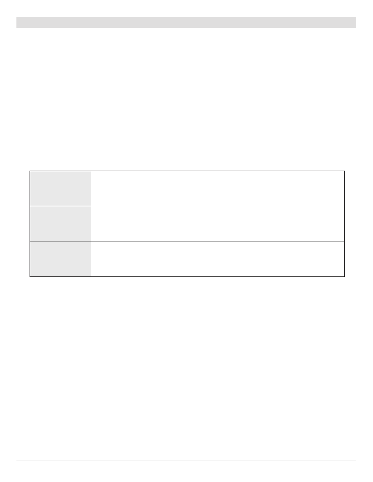
Sonar View
Big Digits View
Sonar Zoom View
For more information, see
Review Sonar History and Zoom In/Zoom Out.
Circular Flasher View
Split Sonar View
For more information, see
Compare Sonar Beams.
Sonar (2D)
For more information, see
Display the Circular Flasher View On-Screen
NOTE: The available views are determined by your control head model and the installed transducer. See each related section of
the manual (Views, Down Imaging, Side Imaging, Navigation Overview, etc.) for more information.
42
Page 43

isplay a Sonar Combo View
D
1. Press and hold the VIEW key.
2. To open a Sonar Combo View, select Sonar.
To open a Chart Combo View (Sonar and Chart together), select Chart.
3. Select a view to display on-screen.
Sonar > Down/Sonar Combo View
For more information, see
the Down Imaging section.
NOTE: The available views are determined by your control head model and the installed transducer. See each related section of
the manual (Views, Down Imaging, Side Imaging, Navigation Overview, etc.) for more information.
Sonar > Side/Sonar Combo View
For more information, see
the Side Imaging section.
Chart > Chart/Sonar Combo View
For more information, see
Navigation Overview.
43
Sonar (2D)
Page 44

UNDERSTAND THE SONAR VIEWS
s the boat moves, the unit charts the changes in depth on the display to create a profile of the bottom contour. The
A
onar View displays the sonar return intensity with different colors.
S
Strong returns often result from rocky or hard bottoms (compacted sediment, rocks, fallen trees), while weaker returns often result
from soft bottoms (sand, mud), vegetation, and small fish.
The colors used to represent high, medium, to low intensity returns are determined by the palette you choose in the Sonar Colors
menu (see Customize the Sonar View).
The control head displays the return intensity based on the Sonar Colors and Bottom View menu settings. You can display the RTS
Window (Real Time Sonar), turn on/off fish symbols (Fish ID+), change the SwitchFire mode, adjust sensitivity, and more.
2D Sonar View: Sonar Colors Palette 1
strong
strong returns
(possibly rocks, tree limbs,
or other structure)
Sonar History — Historical returns scroll left across the view.
weak returns
(possibly vegetation
or small fish)
strong returns
(possibly compacted
sediment or rocks)
Color Bar
weak
medium returns
Sonar (2D)
44
Page 45

CUSTOMIZE THE SONAR VIEW
ou can customize the sonar views by showing or hiding information, such as the temperature graph, depth lines, color bar, and RTS
Y
indow. You can also change the color palette.
W
Customizing the Sonar View
temperature
graph
depth lines
temperature
(digital readout
overlay)
(digital readout
(digital readout
speed
overlay)
depth
overlay)
RTS Window
(A-Scope)
color
bar
45
Sonar (2D)
Page 46

Show/Hide the Frequency Label
he Frequency Label displays the currently selected frequencies. See Set up Sonar.
T
1. Main Menu: Press the MENU key twice. Select the Sonar tab.
. Select Frequency Label.
2
3. Select On (show) or Off (hide).
2D Sonar View Displaying CHIRP Data
selected
display
frequency
selected
frequency
spectrum
Sonar (2D)
46
Page 47

Customize the RTS Window
he RTS Window plots the depth and intensity of a sonar return. It updates at the fastest rate possible for depth conditions and
T
shows only the returns from the bottom, structure, and fish that are within the transducer beam. When you use the cursor to review
sonar history, the sonar history will freeze, but the RTS Window will continue to display sonar returns in real time. See Review Sonar
History and Zoom In/Zoom Out.
1. Main Menu: Press the MENU key twice. Select the Sonar tab.
2. Select RTS Window.
3. Select the type of RTS Window to display.
Mono Sonar returns are displayed in black.
Color (Full) Sonar returns are displayed in color, and they fill the width of the RTS Window.
Color (A-Scope)
Off The RTS Window is hidden.
Sonar returns are displayed in color. The size of the displayed lines correspond with the
intensity of the sonar returns from the transducer beam(s).
Show/Hide Data on the Sonar View
The settings in this section are shared with the Down Imaging View, so turning them on or off will change what is shown on the Sonar
Views and the Down Imaging Views.
1. Main Menu (Advanced User Mode): Press the MENU key twice. Select the Sonar tab.
2. Select a menu and change it to On (show) or Off (hide).
Depth Lines
Color Bar
The depth lines show incremental marks between the upper and lower depth range. See Adjust
Sonar Display Settings for details.
The Color Bar shows the palette selected on the Sonar View (see Change the View Colors) from
weak to strong returns.
Temperature
Graph
NOTE: Digital readouts can be displayed as an overlay, or they can be displayed in data boxes (see Views: Display Digital
Readouts).
The temperature graph displays the temperature changes over the recent sonar history. A
temperature input from the installed transducer or temp/speed accessory is required to enable
this feature.
47
Sonar (2D)
Page 48

Change the View Colors
The Sonar Colors menu changes the colors used to display sonar returns on the view.
Sonar View with Customized Sonar Colors
color bar with
sonar colors set
to palette 4
Strong
Change the Sonar Colors Palette
1. Sonar X-Press Menu: With a Sonar View displayed on-screen, press the MENU key once.
2. Select Sonar Colors.
3. Select a palette.
NOTE: To display or hide the Color Bar, see Show/Hide Data on the Sonar View.
Weak
RTS Window
Sonar (2D)
48
Page 49

Adjusting the Contrast
The high Contrast
setting uses the
top portion of
palette.
color bar
Select a Range of the Palette (Contrast)
Contrast allows you to choose a range of the Sonar Colors palette to display sonar returns. To see the current palette, display the
Color Bar on the Sonar View.
NOTE: To display or hide the Color Bar, see Show/Hide Data on the Sonar View.
When Contrast is set to 20 (default), the entire Sonar Colors palette (represented by the Color Bar) is used to display weak and strong
sonar returns. As you increase the Contrast, the top range of the Color Bar is used to display all sonar returns (whether weak or
strong). As you decrease the Contrast, the bottom range of the Color Bar is used to display all sonar returns (whether weak or
strong).
1. Sonar X-Press Menu: With a Sonar View displayed on-screen, press the MENU key once.
2. Select Contrast.
3. Press the RIGHT or LEFT Cursor keys to move the selection higher or lower on the color bar.
49
Sonar (2D)
Page 50

ADJUST SONAR DISPLAY SETTINGS
se the instructions in this section to adjust how the sonar returns are shown on the Sonar View, so you can tune into what you want
U
o see in the display. The settings in this section are optional. You can use the default display settings for the Sonar View, or you
t
an customize it with your preferences.
c
Filter Surface Clutter
Use Surface Clutter to reduce the noise that may appear at the top of the view caused by algae and aeration. The lower the setting,
the less surface clutter will be displayed. A higher setting allows more surface clutter to be displayed.
OTE: You can also adjust the Noise Filter (see Set up Sonar: Adjust the Noise Filter).
N
1. Main Menu: Press the MENU key twice. Select the Sonar tab.
2. Select Surface Clutter.
3. Press the RIGHT or LEFT Cursor keys to adjust the setting.
Change the 2D SwitchFire Mode
SwitchFire controls how the sonar returns are displayed in the Sonar Views.
1. Main Menu: Press the MENU key twice. Select the Sonar tab.
2. Select 2D SwitchFire.
3. Select Clear Mode or Max Mode.
2D SwitchFire: Clear Mode 2D SwitchFire: Max Mode
Choose Clear Mode to see less clutter and more fish size accuracy on the display.
When Clear Mode is selected, the clutter is filtered, and sonar returns are
interpreted to provide more details about the objects within the transducer beam,
regardless of their location. In other words, a large arch on the display means a
large fish has been detected.
Choose Max Mode to see only raw sonar returns on the display. When Max Mode
is selected, you will see the maximum sonar information available within the
transducer beam, so more fish arches and better jig tracking are shown.
Sonar (2D)
50
Page 51

Turn on/off Fish ID+ Settings
ish ID+ uses advanced signal processing to interpret sonar returns and will display a fish symbol on the Sonar View when very
F
selective requirements are met. Also, if Fish ID+ is turned on, you can adjust the sensitivity used for detection and receive alerts with
the Fish ID Alarm turned on.
Fish ID+ Turned On
depth
Fish ID+ symbol
(200 kHz beam)
Turn on/off Fish ID+
When Fish ID+ is turned on, fish symbols will be shown on the Sonar View. The color of the fish symbols indicates the sonar beam
location, and the fish depth is shown above the symbol.
When Fish ID+ is turned off, the control head shows only the raw sonar returns on the display.
1. Main Menu: Press the MENU key twice. Select the Sonar tab.
2. Select Fish ID+.
3. Select On or Off.
Fish Symbols will display in the Sonar View when a fish is detected.
On
Off
Orange Fish Symbols = targets detected in the 200 kHz narrow beam.
Green Fish Symbols = targets detected in the 83 kHz wide beam (HELIX SONAR G2, HELIX
CHIRP GPS G2, HELIX CHIRP SI GPS G2) or 455 kHz beam (HELIX DI G2, HELIX CHIRP DI GPS G2).
Raw sonar returns are shown on the Sonar View. If a fish is detected, the returns appear as
arches on the display to indicate potential targets.
51
Sonar (2D)
Page 52

djust the Fish ID Sensitivity
A
Use Fish ID Sensitivity to adjust the threshold used for detecting a fish with Fish ID+. To display only larger species of fish as fish
symbols, select a low setting. To see smaller fish species or baitfish, select a high setting. Fish ID+ must be turned on to enable this
menu.
1. Turn on Fish ID+.
2. Main Menu: Press the MENU key twice. Select the Sonar tab.
3. Select Fish ID Sensitivity.
4. Press the RIGHT or LEFT Cursor keys to adjust the setting.
1 = low sensitivity (large fish only)
10 = high sensitivity (All: small fish up to large fish)
Turn on the Fish ID Alarm
To receive an on-screen alert when a fish is detected, turn on the Fish ID Alarm. Fish ID+ must be turned on to enable this alarm.
1. Turn on Fish ID+.
2. Main Menu: Press the MENU key twice. Select the Alarms tab.
3. Select Fish ID Alarm.
4. Select one of the following icons:
Off
All
Large/Medium
Large
Sonar (2D)
52
Page 53

Set the Bottom View Display
ottom View selects the method used to represent bottom and structure on the display. Bottom View is also affected by the palette
B
selected in Sonar Colors (see Customize the Sonar View: Change the View Colors).
Bottom View set to WhiteLine
color bar with
sonar colors
set to palette 1
white shows
strongest
returns
Change the Bottom View Setting
1. Main Menu: Press the MENU key twice. Select the Sonar tab.
2. Select Bottom View.
3. Select one of the following modes:
Structure ID
WhiteLine
Structure ID will display the strongest return as specified by the palette selected in the Sonar
Colors menu.
WhiteLine highlights the strongest sonar returns in white. This has the benefit of clearly
defining the bottom on the display.
RTS Windowwhite shows strongest returns
53
Sonar (2D)
Page 54

ADJUST SETTINGS WHILE YOU FISH (SO
he X-Press Menu provides menu options to adjust the sensitivity and range as you fish. You can also control how fast the sonar
T
istory scrolls across the screen. The menus allow you to see more or less of the sonar returns from the transducer beams as you
h
djust each setting. Also, you can use key shortcuts on the view.
a
Adjusting Settings from the Sonar X-Press Menu (HELIX CHIRP SI GPS G2)
NAR
X-PR
ESSMENU
)
surface
clutter
upper range
RTS Window
lower range
chart speed
Sonar (2D)
54
Page 55

Adjust the Sensitivity
ensitivity controls how much detail is shown on the view. To eliminate the clutter from the display that is sometimes present in
S
murky or muddy water, decrease the sensitivity. When operating in very clear water or greater depths, increase the sensitivity to see
weaker returns.
Adjust the Sensitivity using the X-Press Menu
Use the following instructions to adjust the sensitivity.
1. Sonar X-Press Menu: With a Sonar View displayed on-screen, press the MENU key once.
2. Select Sensitivity.
3. Press the RIGHT or LEFT Cursor keys to increase or decrease the sensitivity.
Adjust the Sensitivity using the ZOOM Keys
If your control head includes +/-ZOOM keys, you can use them to adjust the sensitivity.
1. With a Sonar View displayed on-screen, press the +ZOOM key or −ZOOM key.
Adjusting the Sensitivity using the +/−ZOOM Keys
55
Decrease SensitivityIncrease Sensitivity
Sonar (2D)
Page 56

djust Beam Sensitivity
A
Your control head model may allow you to adjust the sensitivity of individual frequencies. The available frequencies are determined
by your control head model and the installed transducer. Use the following instructions to adjust a single beam.
1. Main Menu (Advanced User Mode): Press the MENU key twice. Select the Sonar tab.
2. Select 83 kHz Sensitivity or 455 kHz Sensitivity.
CHIRP Models: Select Medium Sensitivity Offset or High (455 kHz) Sensitivity Offset (HELIX CHIRP DI GPS G2 only).
3. Press the RIGHT or LEFT Cursor keys to increase or decrease the sensitivity.
For example, in the illustration shown below, the sensitivity of the 83 kHz beam in the Split Sonar View can be adjusted without
affecting the sensitivity of the 200 kHz sonar returns. For more information about this view, see Compare Sonar Beams.
Increasing the Sensitivity of the 83 kHz Beam (83 kHz/200 kHz)
83 kHZ
lower range
200 kHZ
upper range
lower rangefrequency frequency
Select a Range of the Palette (Contrast)
Contrast allows you to choose a range of the Sonar Colors palette to display sonar returns. To see the current palette, display the
Color Bar on the Sonar View. For details, see Customize the Sonar View: Change the View Colors and Show/Hide Data on the Sonar
View.
When Contrast is set to 20 (default), the entire Sonar Colors palette (represented by the Color Bar) is used to display weak and strong
sonar returns. As you increase the Contrast, the top range of the Color Bar is used to display all sonar returns (whether weak or
strong). As you decrease the Contrast, the bottom range of the Color Bar is used to display all sonar returns (whether weak or
strong).
1. Sonar X-Press Menu: With a Sonar View displayed on-screen, press the MENU key once.
2. Select Contrast.
3. Press the RIGHT or LEFT Cursor keys to move the selection higher or lower on the color bar.
Sonar (2D)
56
Page 57

Set the Upper/Lower Range
pper Range and Lower Range control how much of the water column is displayed on the view. For example, if you are only interested
U
in the area between 20 and 50 feet deep, set the Upper Range to 20 and the Lower Range to 50. The view will not display sonar
returns outside of the set ranges, and greater detail for the selected range will be displayed.
1. Sonar X-Press Menu (Advanced User Mode): With a Sonar View displayed on-screen, press the MENU key once.
2. Select Upper Range. Press the RIGHT or LEFT Cursor keys to adjust the setting.
3. Select Lower Range. Select Auto or set a specific depth (manual).
Auto: The Lower Range will be adjusted by the control head to follow the bottom automatically.
Manual : The control head locks onto the depth you select.
NOTE: There must be a difference of 10 feet between the upper and lower range settings.
Change the Chart Speed
Chart Speed controls how fast the sonar history moves across the view and how much detail is shown. A faster speed is preferred
by most anglers, and the sonar history moves quickly across the view. To slow down the sonar history display, select a lower setting.
Regardless of the Chart Speed setting, the RTS Window will update at the maximum rate possible for depth conditions.
1. Sonar X-Press Menu: With a Sonar View displayed on-screen, press the MENU key once.
2. Select Chart Speed.
3. Press the RIGHT or LEFT Cursor keys to adjust the setting.
Turn on/off Jigging Mode (HELIX CHIRP SI GPS G2 only)
If you have a HELIX CHIRP SI GPS G2, you can use Jigging Mode to refine the sonar returns shown in the Sonar View. This setting is
influenced by the whether 2D CHIRP Mode is turned on or off. See Set up Sonar for more information.
1. Sonar X-Press Menu: With a Sonar View displayed on-screen, press the MENU key once.
2. Select Jigging Mode.
3. Select On or Off.
Turn on Jigging Mode if you’ve selected Medium or Medium/High Frequency in the 2D CHIRP
Display Frequency menu (with 2D CHIRP Mode turned on), or if you've selected 83 kHz or 83/200
On
Off
kHz in the 2D Display Frequency menu (with 2D CHIRP Mode turned off). When Jigging Mode is
turned on, the sonar returns are refined on the view, and the chart speed slows down to show
more detail.
Turn off Jigging Mode if you’ve selected Low Frequency in the 2D CHIRP Display Frequency
menu (with 2D CHIRP Mode turned on), or if you've selected 200 kHz in the 2D Display
Frequency menu (with 2D CHIRP Mode turned off). Turn off Jigging Mode to display the sonar
history at the selected chart speed and see coarser returns on the display.
57
Sonar (2D)
Page 58

Change the Sonar Colors Palette
he Sonar X-Press Menu allows you to quickly change the display palette while you fish. See Customize the Sonar View: Change the
T
View Colors for more information.
1. Sonar X-Press Menu: With a Sonar View displayed on-screen, press the MENU key once.
2. Select Sonar Colors.
3. Select a palette.
OTE: To display or hide the Color Bar, see Customize the Sonar View.
N
Switch Frequencies
If the transducer includes more than one downbeam frequency, use the CHECK/INFO key to quickly change the frequency used in
the 2D Sonar View. For more information see Sonar Overview and Set up Sonar.
1. With a Sonar View displayed on-screen, press the CHECK/INFO key.
Using the CHECK key to Switch Frequencies
frequency
label
Sonar (2D)
Switch Frequencies
58
Page 59

COMPARE SONAR BEAMS (SPLIT SONAR VIEW)
Split Sonar View displays sonar returns from each down beam frequency on separate sides of the view. You can use this view to make
side by side comparisons between the sonar returns from both beams. The beams are determined by your Humminbird model and
the installed transducer.
Frequencies: HELIX SONAR G2, HELIX CHIRP GPS G2 models, and HELIX CHIRP SI GPS G2 models allow you to compare the 83
KHz and 200 kHz beams in this view. If you have a HELIX DI G2 or HELIX CHIRP DI GPS G2 model, 455 kHz and 200 kHz will be
displayed side by side in this view. When 2D CHIRP Mode is turned on, you can also compare beams.
Fish ID+: It is also helpful to turn on Fish ID+ in Split Sonar View so you can see where the fish are located within each transducer
beam (see Adjust Sonar Display Settings: Turn on/off Fish ID+ Settings).
Display the Split Sonar View
1. Press and hold the VIEW key.
2. Select Sonar > Split Sonar View.
Reviewing Beams Separately in Split Sonar View (83 kHz/200 kHz)
83 kHZ
lower range
200 kHZ
upper range
lower rangefrequency frequency
59
Sonar (2D)
Page 60

REVIEW SONAR HISTORY
ress any arrow on the Cursor Control key, and the sonar history will freeze and the cursor will display on-screen. If you move the
P
ursor over a sonar return, digital readouts for the cursor position are displayed on the view. The RTS Window continues to update
c
t the fastest rate possible for depth conditions (see Customize the Sonar View).
a
Freeze the Sonar History
1. Press any arrow on the Cursor Control key.
2. Move the cursor over a sonar return.
NOTE: To mark a waypoint or start navigation to the cursor position, see Navigation in Sonar Views.
Reviewing the Depth of the Cursor Position
cursor depth depth below cursor distance to cursor position bearing to cursor position
cursor
digital
readouts
cursor
RTS Window
Move the Cursor
Sonar (2D)
60
Page 61

ZOOM IN/ZOOM OUT
se the Sonar Zoom View to see a magnified view of the bottom and structure. For example, if there are fish close to the bottom
U
r near structure (tree, vegetation, etc.), Sonar Zoom View makes it easier to see the separate sonar returns that might be displayed
o
lose together.
c
Display the Sonar Zoom View
1. Press and hold the VIEW key.
2. Select Sonar > Sonar Zoom View.
Zoom In/Zoom Out using the ZOOM Keys
If your control head includes +/− ZOOM keys, use the instructions in this section to use the ZOOM feature.
Magnify Bottom Structure (Zoom In/Out)
1. Display the Sonar Zoom View on-screen.
2. Zoom In: Press the +ZOOM key.
Zoom Out: Press the –Zoom key.
Magnify the Cursor Position (Zoom In/Out)
1. Display the Sonar Zoom View on-screen.
2. Use the Cursor Control key to move the cursor to a position on the view.
3. Zoom In: Press the +ZOOM key.
Zoom Out: Press the -Zoom key.
4. Close: Press the EXIT key.
61
Sonar (2D)
Page 62

Magnifying Sonar Returns in Sonar Zoom View (Bottom Lock Off)
zoom level upper range, zoom view upper range, full range view
zoomed
view
full range
zoom
preview
range
lower range, zoom view lower range, full range view
OR
ZOOM Out ZOOM InZOOM In
Move the Cursor
Sonar (2D)
62
Page 63

Zoom In/Zoom Out using the X-Press Menu
f your control head does not include ZOOM keys, you will use the Zoom Level menu to use the ZOOM feature.
I
Magnify Bottom Structure (Zoom In/Out)
1. Display the Sonar Zoom View on-screen.
2. Press the MENU key once.
3. Select Zoom Level.
4. Press the RIGHT or LEFT Cursor keys to adjust the setting.
Magnify the Cursor Position (Zoom In/Out)
1. Display the Sonar Zoom View on-screen.
2. Use the Cursor Control key to move the cursor to a position on the view.
3. Press the MENU key once.
4. Select Zoom Level.
5. Press the RIGHT or LEFT Cursor keys to adjust the setting.
6. Close: Press the EXIT key.
63
Sonar (2D)
Page 64

Adjust Sonar Zoom View Display Settings
Turn on/off Bottom Lock
Use Bottom Lock and Bottom Range to focus on the bottom and control how much of the water column is shown in Sonar Zoom
View. Bottom Lock continuously graphs the bottom at a constant point on the display regardless of changes in depth. This “flattens”
out the bottom contour but is effective at showing fish on or near the bottom.
1. Sonar X-Press Menu: With a Sonar Zoom View displayed on-screen, press the MENU key once.
2. Select Bottom Lock. Press the RIGHT Cursor key to select On.
3. Press the UP Cursor key. Select Bottom Range.
4. Press the RIGHT or Left Cursor keys to adjust the range. The range is measured up from the bottom.
Low Setting: useful for seeing low-lying bottom structure or details of the bottom return.
High Setting: useful for seeing large structure in deeper water.
NOTE: If you see a wavy band on the view that mirrors the change in depth, the Bottom Range might be set deeper than the actual
water depth. In this case, decrease the Bottom Range setting.
Change the Width of the Zoomed View
Use the instructions in this section to change the width of the zoomed view in Sonar Zoom View.
1. Main Menu: Press the MENU key twice. Select the Sonar tab.
2. Select Zoom Width.
3. Press the RIGHT or LEFT Cursor keys to adjust the setting.
Setting the Bottom Range and Zoom Width (Bottom Lock On)
zoomed
view
full range
zoom
preview,
bottom
range
Sonar (2D)
zoom width (wide)
64
Page 65

NAVIGATION IN SONAR VIEWS
o mark waypoints and start navigation, the control head must have a GPS Fix from a connected or internal GPS receiver. See
T
etting Started for more information.
G
Mark a Waypoint
You can mark a waypoint at the boat position or the cursor position. Waypoints are saved to the Waypoint Management dialog box
(see Manage your Navigation Data).
Mark a Waypoint at the Boat Position
1. Press the MARK key.
Mark a Waypoint at the Cursor Position
1. Use the Cursor Control key to move the cursor to a position on the view.
2. Press the MARK key twice.
Marking a Waypoint at the Cursor Position
cursor depth depth below cursor distance to cursor position bearing to cursor position
cursor
digital
readouts
Move the Cursor
65
cursor
Press Twice to
Mark a Waypoint
Sonar (2D)
Page 66

Navigate to a Position
Use the instructions in this section to start navigation to a position in the view. See Navigation Overview for more information about
these features.
Navigate to the Cursor Position
1. Use the Cursor Control key to move the cursor to a position on the view.
2. Press the GOTO key twice.
When you press the GOTO key, a waypoint will be marked at the cursor position.
Navigate to a Saved Position
If you press the GOTO key, you can choose to start navigation from a list of saved waypoints and routes.
1. Press the GOTO key.
2. Select Nav Data. Press the RIGHT Cursor key.
3. Use the Cursor Control key to select a saved waypoint or route.
4. Press the RIGHT Cursor key to start navigation.
Cancel Navigation
1. Press the MENU key once.
2. Select Cancel Navigation. Press the RIGHT Cursor key.
Sonar (2D)
66
Page 67

cursor
digital
readouts
Starting Navigation to the Cursor Position
cursor depth depth below cursor distance to cursor position bearing to cursor position
cursor
Move the Cursor
Press Twice to
Start Navigation
67
Sonar (2D)
Page 68

DISPLAY THE CIRCULAR FLASHER VIEW ON-SCREEN
ircular Flasher View provides two ways to view sonar data in traditional flasher format. The view is controlled by the Ice Fishing Mode
C
enu in the Sonar tab.
m
Display the Circular Flasher View
1. Press and hold the VIEW key.
2. Select Sonar > Circular Flasher View.
Circular Flasher View with
Ice Fishing Mode Turned On
Turn on Ice Fishing Mode
1. Main Menu: Press the MENU key twice. Select the Sonar tab.
2. Select Ice Fishing Mode.
3. Select On.
On
Off
When Ice Fishing Mode is on, the Circular Flasher View displays Real Time Sonar (RTS) returns
in traditional flasher format with additional features, including Depth Cursor and Zoom.
When Ice Fishing Mode is off, the Circular Flasher View displays Real Time Sonar (RTS) returns
in traditional flasher format.
Select the Digital Depth Source (HELIX DI G2, HELIX CHIRP DI GPS G2 only)
If you connect an ice transducer to the HELIX DI G2 or HELIX CHIRP DI GPS G2 control head, set the Digital Depth Source to 2D
Element. See Set up Sonar for details.
1. Main Menu (Advanced User Mode): Press the MENU key twice. Select the Sonar tab.
2. Select Digital Depth Source.
3. Select 2D Element.
Circular Flasher
68
Page 69

UNDERSTAND THE CIRCULAR FLASHER VIEW
ou can use the Circular Flasher View with Ice Fishing Mode turned on or off. When Ice Fishing Mode is turned on, the view is
Y
aximized with information you need for ice fishing, including the depth, connected battery power percentage, and related menu
m
ettings.
s
Like a traditional sonar view, the Circular Flasher View displays the sonar return intensity with different colors.
Strong returns often result from rocky or hard bottoms (compacted sediment, rocks, fallen trees), while weaker returns often result
from soft bottoms (sand, mud), vegetation, and small fish.
The colors used to represent high, medium, to low intensity returns are determined by the palette you choose (see Adjust Settings
While you Fish: Change the Sonar Colors Palette).
Circular Flasher View with Ice Fishing Mode Turned On
zoom level
percentage
of power for
connected
battery
sensitivity
depth
NOTE: To change the beam frequency or adjust the noise filter, see Set up Sonar.
69
Circular Flasher
Page 70

ADJUST SETTINGS WHILE YOU FISH (SO
he X-Press Menu provides menu options to adjust the sensitivity and range as you fish. The menus allow you to see more or less
T
f the sonar returns from the transducer beams as you adjust each setting. Also, you can use key shortcuts on the view.
o
Adjusting Settings from the X-Press Menu (HELIX CHIRP SI GPS G2)
NAR
X-PR
ESSMENU
)
Adjust the Sensitivity
Sensitivity controls how much detail is shown on the view. To eliminate the clutter from the display that is sometimes present in
murky or muddy water, decrease the sensitivity. When operating in very clear water or greater depths, increase the sensitivity to see
weaker returns.
Adjust the Sensitivity using the X-Press Menu
Use the following instructions to adjust the sensitivity.
1. Circular Flasher X-Press Menu: With the Circular Flasher View displayed on-screen, press the MENU key once.
2. Select Sensitivity.
3. Press the RIGHT or LEFT Cursor keys to increase or decrease the sensitivity.
Circular Flasher
70
Page 71

Select a Range of the Palette (Contrast)
ontrast allows you to choose a range of the Color Palette to display sonar returns. You can see a preview of the palette in the Color
C
Palette menu. For details, see Change the Sonar Colors Palette.
When Contrast is set to 20 (default), the entire palette is used to display weak and strong sonar returns. As you increase the
Contrast, the right range of the palette is used to display all sonar returns (whether weak or strong). As you decrease the Contrast,
the left range of the palette is used to display all sonar returns (whether weak or strong).
1. Circular Flasher X-Press Menu: With the Circular Flasher View displayed on-screen, press the MENU key once.
2. Select Contrast.
3. Press the RIGHT or LEFT Cursor keys to move the selection left or right on the palette.
Adjusting the Contrast
The low Contrast setting uses the left portion of the palette.
Set the Upper/Lower Range
Upper Range and Lower Range control how much of the water column is displayed on the view. For example, if you are only interested
in the area between 20 and 50 feet deep, set the Upper Range to 20 and the Lower Range to 50. The view will not display sonar
returns outside of the set ranges, and greater detail for the selected range will be displayed.
1. Circular Flasher X-Press Menu: With the Circular Flasher View displayed on-screen, press the MENU key once.
2. Select Upper Range. Press the RIGHT or LEFT Cursor keys to adjust the setting.
3. Select Lower Range. Select Auto or set a specific depth (manual).
Auto: The Lower Range will be adjusted by the control head to follow the bottom automatically.
Manual : The control head locks onto the depth you select.
NOTE: There must be a difference of 10 feet between the upper and lower range settings.
71
Circular Flasher
Page 72

Change the Sonar Colors Palette
he X-Press Menu allows you to quickly change the display palette while you fish. If Ice Fishing Mode is on, additional palettes are
T
available (F1, F2, F3). The Color Palette menu shows a preview of the palette, and the weak to strong sonar return range is displayed
from left to right.
1. Circular Flasher X-Press Menu: With the Circular Flasher View displayed on-screen, press the MENU key once.
2. If Ice Fishing Mode is on, select Color Palette.
If Ice Fishing Mode is off, select Sonar Colors.
3. Select a palette.
Changing the Color Palette
palette preview (weak to strong)
Turn on/off Jigging Mode (HELIX CHIRP SI GPS G2 only)
If you have a HELIX CHIRP SI GPS G2, you can use Jigging Mode to refine the sonar returns shown in the Sonar View. This setting is
influenced by the whether 2D CHIRP Mode is turned on or off. See Set up Sonar for more information.
1. Circular Flasher X-Press Menu: With a Sonar View displayed on-screen, press the MENU key once.
2. Select Jigging Mode.
3. Select On or Off.
Circular Flasher
72
Page 73

Turn on Jigging Mode if you’ve selected Medium or Medium/High Frequency in the 2D CHIRP
Display Frequency menu (with 2D CHIRP Mode turned on), or if you've selected 83 kHz or 83/200
On
kHz in the 2D Display Frequency menu (with 2D CHIRP Mode turned off). When Jigging Mode is
urned on, the sonar returns are refined on the view, and the chart speed slows down to show
t
more detail.
Turn off Jigging Mode if you’ve selected Low Frequency in the 2D CHIRP Display Frequency
Off
menu (with 2D CHIRP Mode turned on), or if you've selected 200 kHz in the 2D Display
Frequency menu (with 2D CHIRP Mode turned off). Turn off Jigging Mode to display the sonar
history at the selected chart speed and see coarser returns on the display.
Switch Frequencies
If the transducer includes more than one downbeam frequency, use the CHECK/INFO key to quickly change the frequency used in
the Circular Flasher View. For more information see Set up Sonar.
1. Press the CHECK/INFO key.
Using the CHECK key to Switch Frequencies
Switch Frequencies
73
frequency
label
Circular Flasher
Page 74

MOVE THE DEPTH CURSOR
Use the Depth Cursor to identify a depth on the Circular Flasher View.
OTE: Ice Fishing Mode must be turned on to enable this feature (see Display the Circular Flasher View On-Screen).
N
1. Activate: Press the DOWN Cursor key, and the purple cursor line will display on the dial.
2. Adjust the Cursor: Press the UP or DOWN Cursor keys.
3. EXIT: Press the EXIT key.
Circular Flasher View with Depth Cursor Displayed
depth cursor
setting
Move the Cursor
depth cursor
(purple line)
Circular Flasher
74
Page 75

ZOOM IN/OUT IN CIRCULAR FLASHER VIEW
The Zoom feature displays a 2x magnified view of the area you choose on the Circular Flasher View.
OTE: Ice Fishing Mode must be turned on to enable this feature (see Display the Circular Flasher View On-Screen).
N
ZOOM In/Out using the ZOOM Keys
1. Activate: Press the +ZOOM key.
2. Adjust the Zoom Range: Press the RIGHT or LEFT Cursor keys to move the white zoom lines on the flasher dial.
3. Close Zoom: Press -ZOOM key.
ZOOM In/Out using the Circular Flasher X-Press Menu
If your control head model does not include ZOOM keys, you will use the Zoom Level menu.
1. Circular Flasher X-Press Menu: With the Circular Flasher View displayed on-screen, press the MENU key once.
2. Select Zoom Level.
3. Select 2X.
4. Adjust the Zoom Range: Press the RIGHT or LEFT Cursor keys to move the white zoom lines on the flasher dial.
5. Close Zoom: Press the MENU key. Select Zoom Level > 1X.
75
Circular Flasher
Page 76

Magnifying Sonar Returns in the Circular Flasher View
(reading the full depth
normal view
of the water column)
zoom line
(lower limit)
zoom line
(upper limit)
zoom view
(2X magnification)
Circular Flasher
ZOOM In
Move the Zoom Range
76
Page 77

DISPLAY A DOWN IMAGING VIEW ON-SCREEN (DO
here are a variety of views available to display Down Imaging data. You can also customize the view by showing or hiding information
T
see Customize the Down Imaging View), and you can adjust the sonar settings to refine the information displayed on-screen (see
(
djust Settings While you Fish). The changes you make are applied to all Down Imaging views.
A
WNIMAGING ANDSIDEIMAGING MODELS ONLY
Display a Down Imaging View
1. Press and hold the VIEW key.
2. Select Sonar > Down Imaging View.
Down Imaging View
)
Display a Down Imaging Combo View
1. Press and hold the VIEW key.
2. To open a Down Imaging Combo View, select Sonar.
To open a Chart Combo View (Down Imaging and Chart together), select Chart.
3. Select a view to display on-screen. Press the RIGHT Cursor key.
Sonar > Down/Sonar Combo View
For more information, see
the Sonar section.
NOTE: The available views are determined by your control head model and the installed transducer. See each related section of
the manual (Views, Sonar, Side Imaging, Navigation Overview, etc.) for more information.
Sonar > Down/Side/Sonar Combo View
For more information, see
the Sonar and Side Imaging sections.
Chart > Chart/Down Combo View
For more information, see
Navigation Overview.
77
Down Imaging Sonar
Page 78

UNDERSTAND THE DOWN IMAGING VIEW
he images you see on the Down Imaging display are produced using sonar technology. Each time the unit pings, a strip of data
T
epresenting all the echoes received by the transducer are put together on the display to form the image that you see. Like traditional
r
D Sonar, the sonar history scrolls left across the screen.
2
Down Imaging beams “illuminate” the bottom contour, structure, and fish. The beams are wide (side to side) but very thin from front
to back.
Down Imaging View
white
streaks/clouds
dark shades
light shades
light shadesshadow
Sonar History — Historical returns scroll left across the view.
Use the light and dark parts of the display to interpret the objects under your boat as follows:
Dark shades represent soft returns (mud, sand) or descending terrain.
Light shades represent denser terrain (timber, rocks) or rising terrain. A very hard bottom may appear as white on the display.
White Streaks or Clouds may represent fish on the display.
Shadows are not caused by light but by the lack of a sonar return. Objects standing on the bottom cause a sonar shadow to
appear on the display. The longer the shadow, the taller the object. Fish may also cast shadows. You can use the shadow to
interpret where the fish or object is located in relation to the bottom.
Down Imaging Sonar
78
Page 79

CUSTOMIZE THE DOWN IMAGING VIEW
ou can customize the Down Imaging views by showing or hiding information, such as depth lines, temperature graph, and digital
Y
eadouts. You can also change the color palette.
r
Customizing the Down Imaging View
temperature
graph
digital
readouts set
to boxes
depth
lines
NOTE: Digital readouts can be displayed as an overlay, or they can be displayed in data boxes (see Views: Display Digital
Readouts).
Show/Hide Depth Lines
The depth lines show incremental marks between the upper and lower depth range. See Adjust Settings While you Fish for details.
The Depth Lines menu is shared with the Sonar View, so turning them on or off will affect the Sonar Views and the Down Imaging
Views.
1. Main Menu (Advanced User Mode): Press the MENU key twice. Select the Sonar tab.
2. Select Depth Lines.
3. Select On (show) or Off (hide).
Show/Hide the Temperature Graph
The temperature graph displays the temperature changes over the recent sonar history. A temperature input from the installed
transducer or temp/speed accessory is required to enable this feature. The Temperature Graph menu is shared with the Sonar
View, so turning it on or off will affect the Sonar Views and the Down Imaging Views.
1. Main Menu: Press the MENU key twice. Select the Sonar tab.
2. Select Temperature Graph.
3. Select On (show) or Off (hide).
79
Down Imaging Sonar
Page 80

Change the View Colors
The DI Colors menu changes the palette used to display sonar returns on the view.
Down Imaging View with Palette 10 Selected (DI Colors)
Change the Down Imaging Colors Palette
1. Down Imaging X-Press Menu: With a Down Imaging View displayed on-screen, press the MENU key once.
2. Select DI Colors.
3. Select a palette.
Down Imaging Sonar
80
Page 81

Show/Hide the Frequency Label
he Frequency Label displays the currently selected frequencies. See Set up Sonar.
T
1. Main Menu: Press the MENU key twice. Select the Sonar tab.
. Select Frequency Label.
2
3. Select On (show) or Off (hide).
Down Imaging View with the Frequency Label Turned On
selected display
frequency
81
Down Imaging Sonar
Page 82

ADJUST SETTINGS WHILE YOU FISH (DO
he X-Press Menu provides menu options to adjust the sensitivity and range as you fish. You can also control how fast the sonar
T
istory scrolls across the screen. The menus allow you to see more or less of the sonar returns from the transducer beams as you
h
djust each setting. Also, you can use key shortcuts on the view.
a
Adjusting Settings from the Down Imaging X-Press Menu
WNIMAGING
X-PR
ESSMENU
upper range
)
chart speed
lower range
Down Imaging Sonar
82
Page 83

Adjust Sensitivity
ensitivity controls how much detail is shown on the view. You can adjust sensitivity from the X-Press Menu or the DI Enhance menu
S
(see Enhance the Down Imaging View). The sensitivity can also be adjusted using the +/− ZOOM keys.
Decrease the sensitivity to eliminate the clutter from the display that is sometimes present in murky or muddy water. When
operating in very clear water or greater depths, increase the sensitivity to see weaker returns.
Adjust the Sensitivity using the X-Press Menu
1. Down Imaging X-Press Menu: With a Down Imaging View displayed on-screen, press the MENU key once.
2. Select Down Sensitivity.
3. Press the RIGHT or LEFT Cursor keys to increase or decrease the sensitivity.
Adjust the Sensitivity using the ZOOM Keys
If your control head includes +/-ZOOM keys, you can use them to adjust the sensitivity.
1. With a Sonar View displayed on-screen, press the +ZOOM key or −ZOOM key.
Adjusting the Sensitivity using the +/−ZOOM Keys
83
Decrease SensitivityIncrease Sensitivity
Down Imaging Sonar
Page 84

Enhance the Down Imaging View
he DI Enhance menu allows you to adjust the sensitivity, contrast, and sharpness on the Down Imaging View. As you adjust each
T
setting, the changes are displayed immediately on the view.
Enhancing the Down Imaging View
Enhance the Down Imaging View
1. Down Imaging X-Press Menu: With a Down Imaging View displayed on-screen, press the MENU key once.
2. Select DI Enhance. Press the RIGHT Cursor key.
3. Use the Cursor Control key to select each menu and adjust the setting.
Sensitivity controls how much detail is shown on the view. Decrease the sensitivity to eliminate
the clutter from the display that is sometimes present in murky or muddy water. When
Sensitivity
Contrast
Sharpness Turn on sharpness and select a filter level to sharpen the edges of the Down Imaging data.
operating in very clear water or greater depths, increase the sensitivity to see weaker returns
that may be of interest. This menu can also be adjusted from the Down Imaging X-Press Menu
(DI Sensitivity).
Adjust the Contrast setting to accent the light and dark parts of the Down Imaging data to
provide greater definition. To intensify the strong returns, increase the contrast. To intensify
the weak returns, decrease the contrast.
Down Imaging Sonar
84
Page 85

Set the Upper/Lower Range
pper Range and Lower Range control how much of the water column is displayed on the view. For example, if you are only interested
U
in the area between 20 and 50 feet deep, set the Upper Range to 20 and the Lower Range to 50. The view will not display sonar
returns outside of the set ranges, and greater detail for the selected range will be displayed.
1. Down Imaging X-Press Menu (Advanced User Mode): With a Down Imaging View displayed on-screen, press the MENU key
once.
2. Select Upper Range. Press the RIGHT or LEFT Cursor keys to adjust the setting.
3. Select Lower Range. Select Auto or set a specific depth (manual).
Auto: The Lower Range will be adjusted by the control head to follow the bottom automatically.
Manual : The control head locks onto the depth you select.
OTE: There must be a difference of 10 feet between the upper and lower range settings.
N
Change the Chart Speed
Chart Speed controls how fast the sonar history moves across the view and how much detail is shown.
1. Down Imaging X-Press Menu: With a Down Imaging View displayed on-screen, press the MENU key once.
2. Select Chart Speed.
3. Press the RIGHT or LEFT Cursor keys to adjust the setting.
Change the DI Colors
The Down Imaging X-Press Menu allows you to quickly change the display palette while you fish. See Customize the Down Imaging
View: Change the View Colors for more information.
1. Down Imaging X-Press Menu: With a Down Imaging View displayed on-screen, press the MENU key once.
2. Select DI Colors.
3. Select a palette.
Change the Imaging SwitchFire Mode
Imaging SwitchFire controls how the sonar returns are displayed in the Down Imaging and Side Imaging Views.
1. Main Menu: Press the MENU key twice. Select the Sonar tab.
2. Select Imaging SwitchFire.
3. Select Clear Mode or Max Mode.
Clear Mode: Clutter is filtered, and sonar returns are interpreted to provide more details on-screen about the objects within
the transducer beam(s).
Max Mode: The view shows the most sonar information available within the transducer beam(s).
Switch Frequencies
If the transducer includes more than one frequency for Down Imaging, use the CHECK/INFO key to quickly change the frequency used
in the Down Imaging View. For more information see Sonar Overview and Set up Sonar.
1. With a Down Imaging View displayed on-screen, press the CHECK/INFO key.
85
Down Imaging Sonar
Page 86

REVIEW DOWN IMAGING HISTORY AND ZOOM IN/OUT
n addition to adjusting the sonar settings while you fish, you can freeze the sonar history, magnify sonar returns, and review position
I
nformation.
i
Freeze the Down Imaging View
Press any arrow on the Cursor Control key, and the sonar history will freeze and the cursor will display on-screen. If you move the
cursor over a sonar return, digital readouts for the cursor position are displayed on the view.
1. Press any arrow on the Cursor Control key.
2. Move the cursor over a sonar return.
3. Review the cursor position and depth information in the digital readouts.
NOTE: To mark a waypoint or start navigation to the cursor position, see Navigation in Down Imaging Views.
Zoom In/Zoom Out using the X-Press Menu
If your control head does not include ZOOM keys, you will use the X-Press menu to magnify a selected part of the view.
1. Use the Cursor Control key to move the cursor to a position on the view.
2. Press the MENU key once.
3. Select DI Zoom.
4. Press the RIGHT or LEFT Cursor keys to adjust the setting.
5. Close: Turn off DI Zoom.
Zoom In/Zoom Out using the ZOOM Keys
If your control head includes +/−ZOOM keys, use the instructions in this section to magnify the selected part of the view.
1. Use the Cursor Control key to move the cursor to a position on the view.
2. Zoom In: Press the +ZOOM key.
Zoom Out: Press the −ZOOM key.
3. Close: Press the EXIT key.
Down Imaging Sonar
86
Page 87

cursor
digital
readouts
zoom box
can be
moved with
the Cursor
Control key
Zooming into the Down Imaging History
cursor depth depth below cursor distance to cursor position bearing to cursor position
zoom level
Move the Cursor
ZOOM In ZOOM Out
87
Down Imaging Sonar
Page 88

NAVIGATION IN DOWN IMAGING VIEWS
o mark waypoints and start navigation, the control head must have a GPS Fix from a connected or internal GPS receiver. See
T
etting Started for more information.
G
Mark a Waypoint
You can mark a waypoint at the boat position or the cursor position. Waypoints are saved to the Waypoint Management dialog box
(see Manage your Navigation Data).
Mark a Waypoint at the Boat Position
1. Press the MARK key.
Mark a Waypoint at the Cursor Position
1. Use the Cursor Control key to move the cursor to a position on the view.
2. Press the MARK key twice.
Marking a Waypoint at the Cursor Position
cursor depth depth below cursor distance to cursor position bearing to cursor position
cursor
digital
readouts
cursor
Down Imaging Sonar
Move the Cursor
Press Twice to
Mark a Waypoint
88
Page 89

Navigate to a Position
Use the instructions in this section to start navigation to a position in the view. See Navigation Overview for more information about
these features.
Navigate to the Cursor Position
1. Use the Cursor Control key to move the cursor to a position on the view.
2. Press the GOTO key twice.
When you press the GOTO key, a waypoint will be marked at the cursor position.
Navigate to a Saved Position
If you press the GOTO key, you can choose to start navigation from a list of saved waypoints and routes.
1. Press the GOTO key.
2. Select Nav Data. Press the RIGHT Cursor key.
3. Use the Cursor Control key to select a saved waypoint or route.
4. Press the RIGHT Cursor key to start navigation.
Cancel Navigation
1. Press the MENU key once.
2. Select Cancel Navigation. Press the RIGHT Cursor key.
89
Down Imaging Sonar
Page 90

DISPLAY A SIDE IMAGING VIEW ON-SCREEN ( HELIX CHIRP SI GPS G2 O
here are a variety of views available to display Side Imaging data. You can also customize the view by showing or hiding information
T
see Customize the Side Imaging View), and you can adjust the sonar settings to maximize the information displayed on-screen
(
see Adjust Settings While you Fish). The changes you make are applied to all Side Imaging views.
(
NLY
Display a Side Imaging View
1. Press and hold the VIEW key.
2. Select Sonar > Side Imaging View.
Side Imaging View
)
Display a Side Imaging Combo View
1. Press and hold the VIEW key.
2. To open a Side Imaging Combo View, select Sonar.
To open a Chart Combo View (Side Imaging and Chart together), select Chart.
3. Select a view to display on-screen. Press the RIGHT Cursor key.
Sonar > Side/Sonar Combo View
For more information, see
the Sonar section.
NOTE: The available views are determined by your control head model and the installed transducer. See each related section of
the manual (Views, Sonar, Down Imaging, Navigation Overview, etc.) for more information.
Sonar > Down/Side/Sonar Combo View
For more information, see
the Sonar and Down Imaging sections.
Chart > Chart/Side Combo View
For more information, see
Navigation Overview.
Side Imaging Sonar
90
Page 91

UNDERSTAND THE SIDE IMAGING VIEW
ide Imaging beams “illuminate” the bottom contour, structure, and fish. The side beam coverage is very thin from front to back,
S
et very wide from top to bottom. The bottom composition determines the intensity of the sonar return, and upward slopes that face
y
he transducer reflect sonar better than downward slopes that face away from the transducer.
t
Side Imaging View
Side Imaging sonar returns are first
displayed at the top of the screen, and
historical data scrolls down the display
as new information is received.
boat icon
water column
light shades
dark shades
shadowswhite streaksdark shades
Use the light and dark parts of the display to interpret the objects on the view as follows:
Shadows: The longer the shadow, the taller the object. Fish also cast shadows, and their distance from the bottom can be
interpreted by their shadow.
Light Shades represent denser terrain (possibly compacted sediment, timber, rocks) or rising terrain.
Water Column: shows the relative depth of the water under the boat at any given time. Variations in the width of the water
column show variations in the distance to the bottom as the boat passes over. See the illustration Interpreting the Side
Imaging View.
White Streaks or Clouds may represent fish on the display.
Dark Shades represent soft returns (possibly sand or mud) or descending terrain.
91
Side Imaging Sonar
Page 92

nterpreting the Side Imaging View
I
To visualize how Side Imaging works, the Side Imaging View illustration can be folded down the middle and then folded again at the
lowest point of the water column. The raised area reveals the water column with its relative depth of the water under the boat. In
the Side Imaging View, variations in the width of the water column show variations in the distance to the bottom as the boat passes
over.
For Best Side Imaging Performance
• Boat Speed: trolling
• Straight line navigation
• Minimum turning time and wave turbulence
Also, see humminbird.com for tutorials and Side Imaging videos.
Side Imaging Sonar
92
Page 93

CUSTOMIZE THE SIDE IMAGING VIEW
he settings in this section are optional. You can use the default settings for the view, or you can customize it with your preferences.
T
Showing Digital Readouts and SI Range Lines
range
numbers
digital readouts
set to boxes
range lines
Show/Hide SI Range Lines
SI Range Lines divide each side beam range into equal sections on the Side Imaging View. Use the range lines to estimate the
location of objects. You can show or hide range lines on the view.
NOTE: The range numbers are estimated and should not be used for measurement. If SI Range Lines and Contour Mode are turned
on, the SI Range Lines will remain on the display, but the individual range numbers will not be available.
1. Main Menu: Press the MENU key twice. Select the Sonar tab.
2. Select SI Range Lines.
3. Select On (show) or Off (hide).
Show/Hide Digital Readouts on the Side Imaging View
If you have Digital Readouts set to Boxes on all views, you can hide the digital readout boxes on the Side Imaging View exclusively.
For details, see Views: Display Digital Readouts.
1. Main Menu: Press the MENU key twice. Select the Sonar tab.
2. Select SI Readouts
3. Select On (show) or Off (hide).
93
Side Imaging Sonar
Page 94

Change the View Colors
The SI Colors menu changes the colors used to display sonar returns on the view.
1. Side Imaging X-Press Menu: With a Side Imaging View displayed on-screen, press the MENU key once.
2. Select SI Colors.
3. Select a palette.
Side Imaging View with Palette 1 Displayed
Side Imaging Sonar
94
Page 95

Show/Hide the Frequency Label
he Frequency Label displays the currently selected frequencies. See Set up Sonar.
T
1. Main Menu: Press the MENU key twice. Select the Sonar tab.
. Select Frequency Label.
2
3. Select On (show) or Off (hide).
Side Imaging View with the Frequency Label Turned On
selected display
frequency
95
Side Imaging Sonar
Page 96

ADJUST SETTINGS WHILE YOU FISH (SI
he X-Press Menu provides menu options to adjust the sensitivity and range as you fish. You can also control how fast the sonar
T
istory scrolls down the screen. The menu options allow you to see more or less of the sonar returns from the transducer beams
h
s you adjust each setting. Also, you can use key shortcuts on the view.
a
DEIMAGING
X-PR
ESSMENU
Adjust Sensitivity
Sensitivity controls how much detail is shown on the view. You can adjust sensitivity from the X-Press Menu or the Enhance menu
(see Enhance the Side Imaging View). The sensitivity can also be adjusted using the +/− ZOOM keys.
Decrease the sensitivity to eliminate the clutter from the display that is sometimes present in murky or muddy water. When
operating in very clear water or greater depths, increase the sensitivity to see weaker returns.
Adjust the Sensitivity using the X-Press Menu
1. Side Imaging X-Press Menu: With a Side Imaging View displayed on-screen, press the MENU key once.
2. Select SI Sensitivity.
3. Press the RIGHT or LEFT Cursor keys to increase or decrease the sensitivity.
Adjust the Sensitivity using the ZOOM Keys
If your control head includes +/−ZOOM keys, you can use them to adjust the sensitivity.
)
1. With a Sonar View displayed on-screen, press the +ZOOM key or −ZOOM key.
Side Imaging Sonar
96
Page 97

Adjusting the Sensitivity using the +/−ZOOM Keys
Decrease SensitivityIncrease Sensitivity
97
Side Imaging Sonar
Page 98

Enhance the Side Imaging View
he SI Enhance menu allows you to adjust the sensitivity, contrast, and sharpness on the Side Imaging View. As you adjust each
T
setting, the changes are displayed immediately on the view, so you can fine tune the display. You can also turn on/off the Contour
Mode from this menu so the water column is displayed or hidden on the view.
Enhancing the Side Imaging View
Enhance the Side Imaging View
1. Side Imaging X-Press Menu: With a Side Imaging View displayed on-screen, press the MENU key once.
2. Select SI Enhance. Press the RIGHT Cursor key.
3. Use the Cursor Control key to select each menu and adjust the setting.
Side Imaging Sonar
98
Page 99

Sensitivity controls how much detail is shown on the view. Decrease the sensitivity to eliminate
the clutter from the display that is sometimes present in murky or muddy water. When
Sensitivity
operating in very clear water or greater depths, increase the sensitivity to see weaker returns
hat may be of interest. This menu can also be adjusted from the Side Imaging X-Press Menu
t
(SI Sensitivity).
Adjust the Contrast setting to accent the light and dark parts of the Side Imaging data to
Contrast
provide greater definition. To intensify the strong returns, increase the contrast. To intensify
the weak returns, decrease the contrast.
Sharpness Turn on sharpness and select a filter level to sharpen the edges of the Side Imaging data.
Contour Mode controls how the water column is displayed in the Side Imaging Views. When
Contour Mode is turned off, the water column is displayed on the view. The location of a target
on the display is based on the slant range to the target.
Contour Mode
When Contour Mode is turned on, the bottom is graphed at a constant point on the display,
regardless of changes in depth. The Side Imaging beams are divided by a vertical line. The
water column is removed from the view, which allows the display to show targets at their linear
horizontal distance. The location of a target may be easier to interpret when the water column
is removed.
Contour Mode Off Contour Mode On
The water column is displayed on the Side Imaging View. The water column is removed from the Side Imaging View.
99
Side Imaging Sonar
Page 100

Adjust the Side Imaging Range
I Range sets the deepest range that will be displayed on the Side Imaging views. Choose a low range number to focus on a shorter
S
distance of the water column and see greater detail on the view. Choose a higher range number to see farther into the water and
see an overview of details on the screen.
1. Side Imaging X-Press Menu: With a Side Imaging View displayed on-screen, press the MENU key once.
2. Select SI Range.
Auto: The Range will be adjusted by the control head to follow the bottom automatically.
Manual: The control head locks onto the depth you select.
Side Imaging units default to the Side Imaging range setting if the SI Range is set deeper than the Max Depth. See Set up Sonar
for more information.
Display Beams
Use SI Side to select which Side Imaging beam will be shown on the display.
Side Imaging View with the Left Beam Displayed
left beam
label
boat icon
range lines
Select Beams to Display on the View
1. Side Imaging X-Press Menu: With a Side Imaging View displayed on-screen, press the MENU key once.
2. Select SI Side.
3. Select a beam or both beams to display.
Side Imaging Sonar
100
 Loading...