

Page 1
Page 2

SECTION ONE
LICENSE INFORMATION
It is the responsibility of the user of this radio to ensure that all appropriate licenses have been
obtained prior to operation of the radio.
The FCC Rules and Regulations Part 80 document contains information on the licensing and
operation of VHF radios in the United States. Different applications have different licensing
requirements; however in general, if your boat already has a licensed fixed mount VHF radio, no
additional license may be required.
A FCC form 506 application for ship radiotelephone license is included with this manual. Any
additional applications or documents may be obtained by writing:
Superintendent of Documents
Government Printing Office Washington, D. C. 20402
For licensing information in Canada:
Department of Communication
300 Slater Street
Ottawa. Ontario
K1A OC8
Attn: DOS-PP
SECTION TWO
BEFORE BEGINNING
HOW VHF RADIOS WORK
The Humminbird DC5s hand-held radio is a VHF transceiver. This means that the radio has the
capability to both transmit signals as well as receive them, and operates in the VHF (very high
frequency) spectrum.
The marine band is a group of VHF frequencies between approximately 156 MHz and 163 MHz.
This band is divided into a number of discrete channels, which are numbered and further
categorized by use.
Within the marine band, 10 channels are designated for continuous weather broadcasts. These
channels are grouped into a “Weather Band” and designated “receive only” channels. You cannot
transmit on a weather channel.
The remaining frequencies are assigned for various purposes and given a channel number.
There are basically two different channel numbering and frequency assignment schedules
currently in use, which creates two different bands of frequencies: the USA band and the
International band. These two bands share the same frequencies but assign channel numbers
slightly differently, and allocate these channels for different uses.
A list of USA, International, and Weather bands including channel numbers, frequencies, and
descriptions of use is included in Section 6 of this manual.
AVAILABLE ACCESSORIES
Page 3
Humminbird offers accessories that compliment and expand the capability of your hand-held
radio. These accessories are designed and manufactured to the same high standards as all
Humminbird products, and are backed by the same one-year warranty.
The Humminbird Accessory Catalog includes ordering information and descriptions of many
available accessories. All Humminbird accessories can be ordered at your full-service
Humminbird dealer or factory -direct through our Toll-Free number listed inside the back cover of
this manual.
BP-DC5: Spare battery pack (NiCd 10.8 VDC)
CLC: Cigarette lighter adapter cable. Change or operate your DC5s from a 12 VDC power
source.
WC-1: One-hour fast charger.
SECTION THREE
INSTALLATION
WHAT YOU HAVE
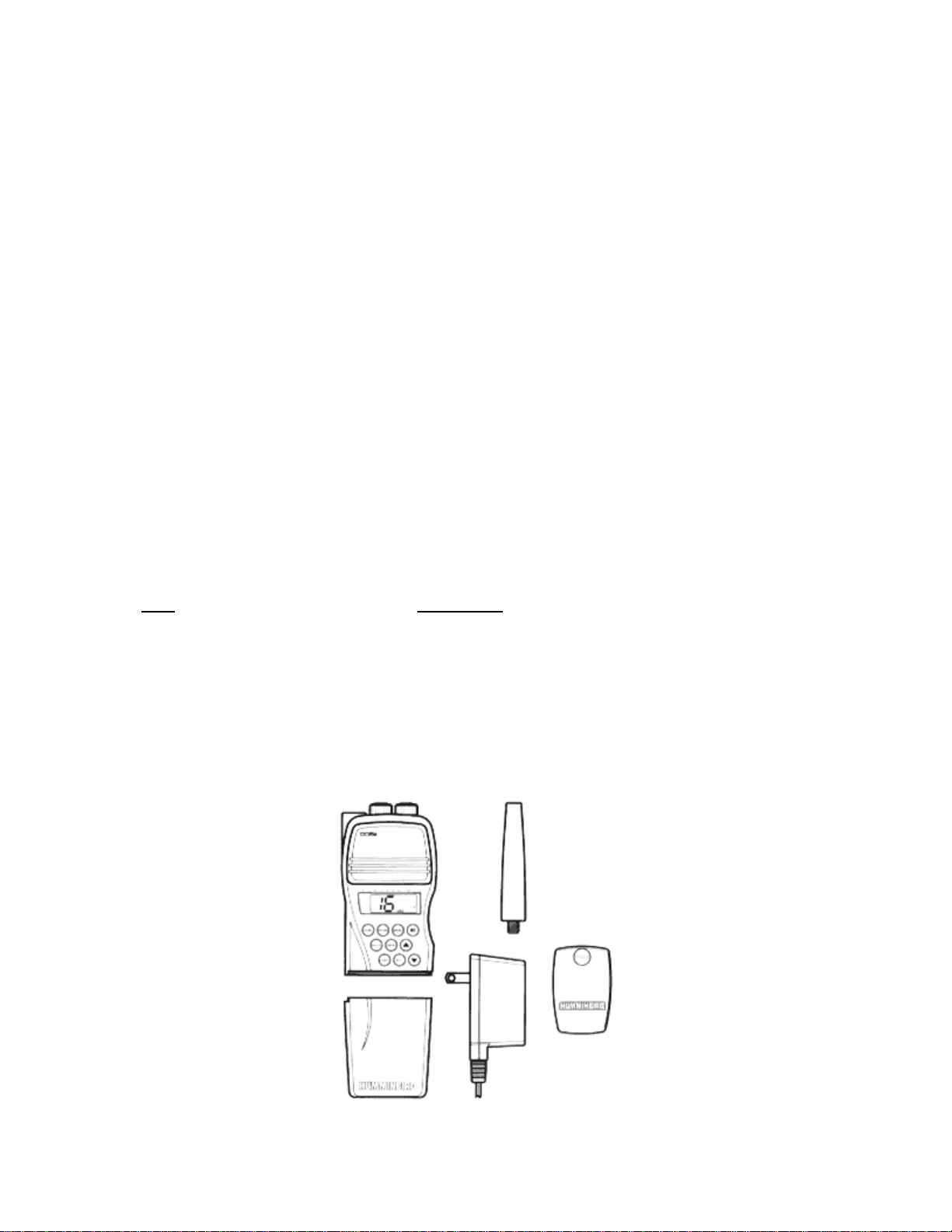
Please ensure that the following items are included in the box:
Item Part Number
Radio…………………………………DC5s
Antenna………………………………N/A
110 VAC charger……………………WA-110
Belt clip………………………………N/A
Operations manual…………………...530355-1
FCC license information……………. N/A
……………………………………………………..
• Charger only included with US/Canadian radios.
Page 4
If any of these items are missing, call our Toll-Free Customer Support Hotline listed inside the
back cover of this manual.
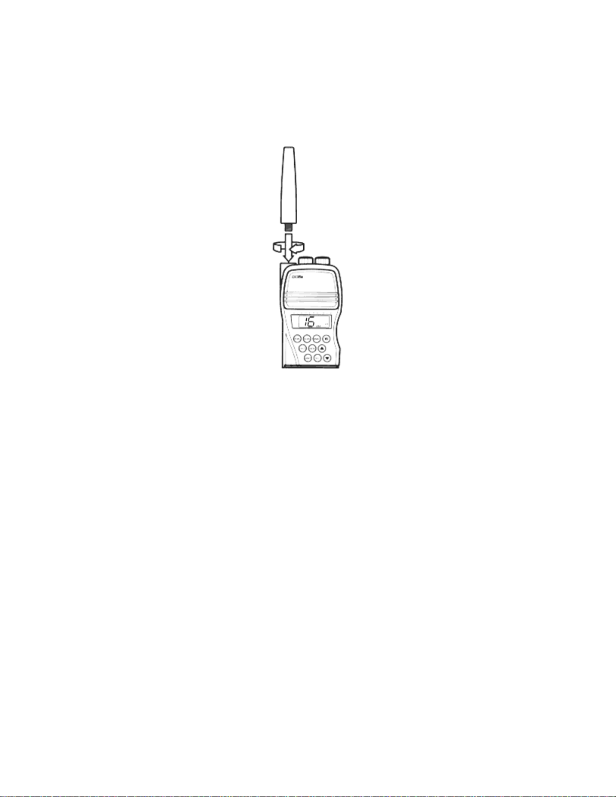
INSTALLING THE ANTENNA
The antenna supplied with your DC5s is specifically tuned to optimize the radio’s transmit power
and the sensitivity of the receiver. To install, ensure the threaded base and the recessed threads
on the unit are free from debris, and screw the antenna into the base. Finger tighten only.
INSTALLING THE BELT CLIP
The belt clip performs two purposes – it can be used to carry the DC5s from a belt or pocket,
and the rubber pad works in conjunction with the charger jack cover to provide a skid-proof
stance when the radio is laying on it’s back.
Page 5
If you choose to use the belt clip included with your DC5s, simply fasten it to the mounting point
using the attached screw. A flat head screwdriver or a small coin can be used. Do not over
tighten the screw or use a fastener other than the one supplied.
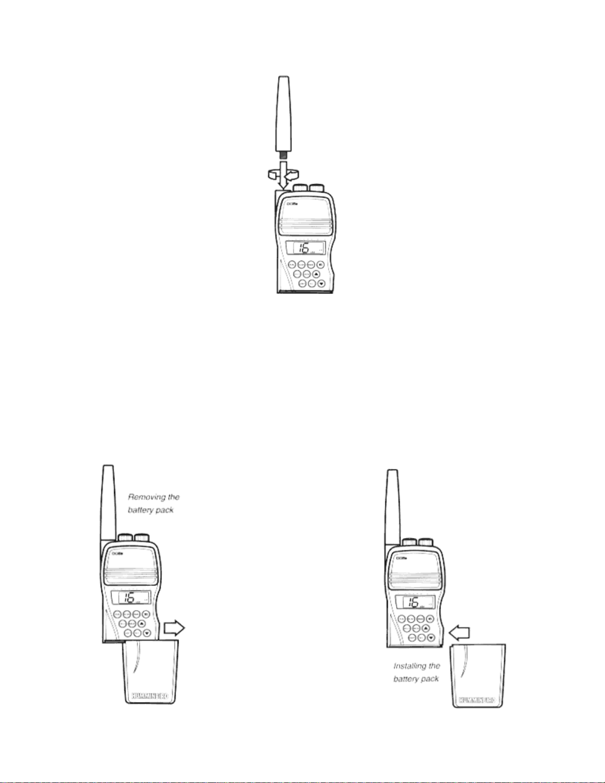
BATTERY REMOVAL AND INSTALLATION
The battery pack is pre-installed on your DC5s. It is not necessary to remove it for charging or
normal operation. If you are using more than one battery pack you can remove the battery pack
by simply sliding it off the DC5s unit. Some force may be necessary to overcome the mechanical
detent.
Page 6
When the battery pack is off the DC5s unit, care should be used to prevent damage to the
mating slide and electrical contacts on the top of the battery. Also the slide and contact area on
the bottom of the unit will be vulnerable to damage if not protected. It is best to keep the battery
pack installed even if the radio is being stored for extended periods.
BATTERY CHARGING
The battery pack included with your DC5s contains Nickel-Cadmium type rechargeable
batteries. Battery charge life (how long the battery will hold a charge) varies with a number of
factors including temperature, frequency of use, use of the transmitter, etc.
Nickel Cadmium batteries are used due to their long operational life. Proper use of your NiCd
batteries will extend both the charge life and the battery life.
NiCd batteries require regular exercises in order to maintain their full potential. A battery that is
kept at full charge continually, by charging over a long period of time (30 days) will develop a
memory effect which considerably shortens the charge life. A more common type of memory
effect is induced by uniform shallow cycling. For example, if a battery is repeatedly operated at
50% of its full capacity.
Ideally, a NiCd battery should be fully charged, fully depleted, fully charged, etc. This exercising
prevents the memory effect and ensures maximum charge life of the battery.
If a battery shows early signs of reduced charge life due to the memory effect, it is easy to
restore the battery to it’s full potential by intentionally exercising the battery several cycles from
full charge to full discharge.
The battery pack can be charged on or off the DC5s unit. Both the 110 VAC adapter and 12
VDC cigarette lighter adapter (available as an accessory) will power the DC5s for normal
operation while maintaining a trickle charge to the battery pack.
Additionally, a 1-hour quick charger is available as an accessory which enables very fast change
cycles from a 110 VAC source.
If the DC5s is used frequently or for an emergency, a back-up battery pack is a good idea.
Before using your DC5s for the first time, the battery should be fully charged. To charge the
DC5s battery, simply plug the charger into the charge jack on the rear of the battery pack. If you
are using the wall charger, the red LED light will illuminate if proper connection is made and the
battery is accepting the charge. When possible, charge the battery at room temperature. Never
charge the battery below 50 degrees F (10 degree C) or above 95 degrees F (35 degrees C)
since this could cause damage to the battery or reduce the charge life.
Page 7

The battery drain is considerably greater when transmitting than receiving. A battery charge can
be maintained for 8 hours or more (depending on ambient temperatures) when receiving only.
Frequent transmitting, especially on High (5 Watt) output power will significantly increase the
battery drain.
The battery will be fully discharged within one month even with power off.
Note: The nickel-cadmium (NiCd) battery contained in the DC5s battery pack must be recycled
or disposed of in an environmentally sound manner. Do not place batteries in your regular trash.
The incineration, land filling or mixing of nickel-cadmium batteries with the municipal solid waste
stream is prohibited by law in some areas. Incineration may cause an explosion. Return the
battery to a federal or state approved nickel –cadmium battery recycler,
Contact your local waste management officials for additional information regarding the
environmentally sound collection, recycling and disposal of this battery or call Humminbird at the
Customer Support number listed inside the rear cover of this manual.
SECTION FOUR
CONTROL FUNCTIONS
Control of the DC5s are divided into three functional areas:
- The Power/Volume and Squelch controls are located on the top of the radio.
- The PTT (push to talk) switch is located on the side of the radio.
- The function control keys are located on the front of the radio.
Page 8

Most control inputs result in audible, tactile, and visual feedback for positive actuation in loud
environments.
POWER AND VOLUME CONTROLS
To power the DC5s for operation, turn the Power/Volume knob clockwise past the detent. Th e
display will illuminate indicating that power is supplied to the DC5s unit. Continue turning the
Volume knob until the desired audio volume is achieved. It may be necessary to adjust the
squelch first, then adjust the volume once a transmission is received.
To turn the DC5s off, turn the Power/Volume knob counter- clockwise until the detent is felt and
the display is blank.
ADJUSTING THE SQUELCH
The squelch is commonly used to eliminate static and background noise from being heard. To
adjust the squelch, ensure that the unit is powered and sufficient volume is available to hear the
speaker. Turn the Squelch knob counter-clockwise as far as it will go. Adjust the volume to the
desired level. Wait for a period when no transmission is being received, and turn the Squelch
slowly clockwise until the background static is eliminated.
The squelch allows silent operation of the DC5s until a transmission is received. If the Squelch
is adjusted too high, only the strongest transmissions will be heard. If the Squelch is adjusted too
low, intermittent static and noise will be heard.
USING THE PTT
The Push To -Talk switch is located on the side of the DC5s and is easily accessible to both left
and right hand users. To activate the PTT, simply press the raised portion of the switch. A tactile
Page 9

click will be felt, and the display will show the TX (transmit) symbol indicating that the unit is
transmitting.
Care should be used to prevent the inadvertent actuation of the PTT switch. When storing the
radio while powered, ensure that nothing comes into contact with the PTT. Inadvertent actuation
will transmit a signal causing interference with other users, possibly interfering with an emergency
broadcast, and will quickly drain the battery as well.
SELECTING THE BAND
Upon power-up, the last selected band will be in operation. The band, USA, INT (International),
or WX (weather) is indicated on the display.
Pressing the BAND button will toggle between these three bands. As with all controls, an
audible chirp will be heard when the button is pressed.
SELECTING THE CHANNEL
Within each of these three bands there are a number of discrete channels. These channels are
selected using the UP and DOWN arrow keys. Pressing either key once will select the next higher
or lower channel. Pressing and holding either arrow key will scroll through all available channels.
USING DUAL WATCH
Channel 16 is the normal monitoring channel for all maritime applications. In some instances,
the government mandates continuous monitoring of channel 16. Dual watch is a useful feature
that allows you to monitor channel 16 and another channel of your choice simultaneously.
Page 10

Select any channel on either USA or INT bands. Press DUAL. The DC5s will monitor your
selected channel and channel 16 simultaneously. If a transmission is heard on either channel,
that channel will continue to be selected until no further transmission is received, then dual watch
will be re-engaged.
When using Dual Watch, the DC5s will also monitor the active WX channel for a special alert
tone issued during times of severe weather. You must select an active WX channel prior to
entering Dual Watch for this feature to work. Should this tone be received, the DC5s will emit an
alarm tone. Pressing the BAND button will switch the broadcast to the weather channel. Pressing
BAND again will exit the WX channel and you may enter Dual Watch again. You cannot enter
Dual Watch from the WX channel.
Pressing DUAL a second time will disable Dual watch.
Pressing the PTT button will also disable Dual watch. Pressing the PTT button a second time
will allow transmission.
USING SCAN
Scan is the sequential monitoring of all channels within the selected band. Pressing SCAN will
cause the DC5s to briefly monitor each channel starting with the current channel, and if no
transmission is heard, move to the next higher channel. If while monitoring a channel a
transmission is heard, the DC5s will remain on that channel until it is clear, then move to the next
channel.
Pressing the SCAN button again will disengage scan.
Pressing the PTT button will also disable scan. Pressing the PTT button a second time will allow
transmission.
USING THE CHANNEL 16 QUICK SELECT
Page 11

Channel 16 is the standard channel for an emergenc y broadcast. The 16 button selects channel
16 quickly from any other channel or band. If the WX band is currently in use, channel 16 on the
USA band is selected. If you are using the DC5s on the INT band when 16 is selected, channel
16 of the INT band is selected.
Channel 16 represents the same frequency on both USA and INT bands.
If 16 is pressed again, the DC5s will return to the previously selected channel.
USING MEMORY
The DC5s is capable of storing up to 10 frequently used channels from either USA or INT
bands. Memory acts as its own band, so that you can scan between memory channels. Weather
channels cannot be stored in memory.
The Memory function consists of two buttons. M+/- and MEM. To store a channel to Memory,
first select that channel, then press M+/-. The MEM enunciator will appear on the display for a
second indicating that the currently selected channel has been stored to Memory. Continue this
procedure for all the frequently used channels you wish to store into memory.
By pressing MEM, the Memory function is selected and the MEM enunciator will be continuously
displayed. When in the MEM function, only channels stored to Memory will be accessible. The Up
and Down arrow keys can be used to select any channel stored to memory. SCAN can be used
to scan only the Memory channels.
At least one channel must be stored in memory in order to access the Memory function.
Pressing MEM when in Memory will return the unit to the previously selected band and channel.
Page 12

To delete a channel from Memory, select the Memory function and ensure the MEM enunciator
is displayed. Use the Up or Down arrow button to select the channel to be deleted, and press
M+/-. The channel is now deleted from memory.
Remember, you must be outside of the Memory function to store a channel to Memory, and the
Memory function must be active to delete a channel from Memory.
Note: Removing the battery pack will erase programmed channels from memory. Programmed
channels may also be lost if the battery charge is low.
USING THE BACKLIGHT
The LIGHT button turns on the backlight for both the display a and the keypad. Pressing the
LIGHT button again will turn the backlight off or, if no button is pressed, the light will go off
automatically after about 10 seconds in order to save battery power.
SELECTING TRANSMIT POWER
The DC5s has a selectable transmit power output. The HI annunciator indicates that the unit will
transmit at 5 watts, the LO annunciator indicates the 1 watt output power is selected. Press HI/LO
to toggle between the two.
Selection of certain channels will cause the DC5s to automatically select the LO power output.
This feature is required by the FCC.
The HI power output will usually result in greater trans mit range, at the expense of battery
consumption. When maximum range is not necessary, selecting LO transmit power will conserve
battery power.
SECTION FIVE
OPERATION
USING THE DC5s
To place a call with the DC5s, turn the power on and adjust the volume and squelch controls.
Use the Up and Down arrow buttons to select the desired channel. Normally, channel 16 is used
for an initial call, then once contact is made with the receiving party, another channel is selected
by both parties to avoid excessive congestion on channel 16.
Page 13

Before transmitting, listen for activity on your channel. Do not interrupt another user.
Press the PTT button to transmit. Pause briefly then speak at a normal volume while holding the
DC5s unit 4-5” from your mouth. Speak directly into the speaker/microphone area. Greatest
range will be achieved when the radio is held vertically, and standing clear of obstructions which
may block the transmitted signal.
Refer to the FCC Rules and Regulations Part 80 for proper VHF radiotelephone procedures and
terminology.
SECTION SIX
SAFETY AND MAINTENANCE
MAINTENANCE
Your Humminbird DC5s radio is designed to provide years of trouble-free operation with virtually
no maintenance. Follow the simple procedures listed below to ensure your DC5s continues to
deliver top performance.
If the DC5s comes into contact with salt spray, simply rinse the unit off with fresh water and a
clean cloth.
When cleaning the protective clear lens, use a non-abrasive cleaner such as mild soap and
water. Avoid using alcohol based glass cleaners as this may weaken the material and cause it to
fail.
Never transmit with the antenna removed from the unit, as this will damage the transmit circuit of
the unit.
Do not remove the housing fasteners or attempt to make repairs to the radio yourself. The case
is sealed to prevent water intrusion and special tools are required for reassembly. Repairs should
be performed by authorized Humminbird technicians only.
Periodically exercise the battery from full charge to fully drained. Keeping the battery continually
at full charge will create a memory effect which reduces the charge life.
Page 14

The battery pack contains Nickel-Cadmium batteries. Use care not to damage the outer case,
and if the battery is no longer operable, dispose of properly. See “Battery Removal and
Installation” section for additional disposal information or call Humminbird’s Customer Support
number listed inside the rear cover of this manual.
Note: Do not dispose of any battery in a fire because it may explode!
SAFETY AND MAINTENANCE
Never leave this or any electronic device in a closed car or trunk – the extremely high
temperatures generated in hot weather can damage temperature sensitive components.
TROUBLESHOOTING
1. The screen begins to fade out. Images on the screen are not as sharp and clear as usual.
Check your battery to see that it is fully charged.
2. Low level or no sound comes from the speaker.
Adjust the VOLUME and SQUELCH knobs as described in Section Four.
3. Sensitivity is low, and only strong signals are audible.
Check the antenna connector for salt spray or dirt. Make sure he antenna connector is properly
seated.
4. The battery only lasts a short period of time.
Restore the full charge capability of the battery by exercising the battery from fully charged to fully
depleted. This exercising prevents the memory effect and ensures maximum charge of the
battery.
TABLES OF MARINE CHANNELS
USA MARINE CHANNELS
TX RX
CH FREQ FREQ COMMENT
…………………………………………………………………………….
1 156.05 156.06 Port Operation, Commercial
2 156.100 156.100 Port Operation
3 156.15 156.15 Port Operation, Commercial
4 156.200 156.200 Port Operation
5 156.25 156.25 Port Operation
6 156.30 156.30 Inership Safety
7 156.35 156.35 Commercial
8 156.40 156.40 Commercial
9 156.45 156.45 Commercial, Non Commercial
10 156.50 156.50 Commercial
11 156.55 156.55 Commercial
12 156.60 156.60 Port Operation
Page 15

13 156.65 156.65 Navigational, (Low)
14 156.70 156.70 Port Operation
15 156.75 Environmental (receive only)
16 156.80 156.80 Distress, Safety, and Calling
17 156.85 156.85 Marine Control, (Low)
18 156.90 156.90 Commercial
19 156.95 156.95 Commercial
20 157.00 161.60 Port Opreation
21 157.05 157.05 US Government Only
22 157.10 157.10 Coast Guard Liaison
23 157.15 157.15 US Government Only
24 157.20 161.80 Public Correspondence
25 157.25 161.85 Public Correspondence
26 157.30 161.90 Public Correspondence
27 157.35 161.95 Public Correspondence
28 157.40 162.00 Public Correspondence
60 156.025 160.625 Port Operation, Public Correspondence
61 156.075 160.675 Port Operation, Public Correspondence
62 156.125 160.725 Port Operation, Public Correspondence
63 156.175 156.175 Port Operation, Commercial
64 156.225 160.825 Port Operation, Public Correspondence
65 156.275 156.275 Port Operation
66 156.325 156.325 Port Operation
67 156.375 156.375 Commercial, (Low)
68 156.425 156.425 Non-Commercial
69 156.475 156.475 Non-Commercial
70 156.525 156.525 Digital Selective Calling
71 156.575 156.575 Non-Commercial
72 156.525 156.625 Non-Commercial
73 156.675 156.675 Port Operation
74 156.725 156.725 Port Operation
75 156.775 Guard Band (receive only)
76 156.825 Guard Band (receive only)
77 156.875 156.875 Port Operation, Intership
78 156.925 156.925 Non-Commercial
79 156.975 156.975 Commercial
80 157.025 156.975 Commercial
81 157.075 157.075 US Government Only
82 157.125 157.125 US Government Only
83 157.175 157.175 US Government Only
84 157.225 161.825 Public Correspondence
85 157.275 161.875 Public Correspondence
86 157.325 161.925 Public Correspondence
87 157.375 161.975 Public Correspondence
88 157.425 157.425 Commercial
INTERNATIONAL MARINE CHANNELS
1 156.05 160.65 Public Correspondence. Port Operation
2 156.10 160.70 Public Correspondence, Port Operation
3 156.15 160.75 Public Correspondence, Port Operation
4 156.20 160.80 Public Correspondence, Port Operation
5 156,25 160.85 Public Correspondence, Port Operation
Page 16

6 156.30 156.31 Safety Compulsory
7 156.35 160.95 Public Correspondence, Port Operation
8 156.40 156.40 Commercial, Intership
9 156.45 156.45 Commercial, Non-Commercial
10 156.50 156.50 Commercial
11 156.55 156.55 Commercial, VTS
12 156.60 156.60 Port Operation, VTS
13 156.65 156.65 Navigational
14 156.70 156.70 Port Operation, VTS
15 156.75 156.75 Environmental (Low)
16 156.80 156.75 Distress, Safety, and Calling
17 156.85 156.85 (Low)
18 156.90 161.50 Port Operation
19 156.95 161.55 Commercial
20 157.00 161.60 Public Correspondence
21 157.05 161.55 Public Correspondence
22 157.10 161.70 Public Correspondence
23 157.15 161.75 Public Correspondence
24 157.20 161.80 Public Correspondence
25 157.25 161.85 Public Correspondence
26 157.30 161.90 Public Correspondence
27 157.35 161.95 Public Correspondence
28 157.40 162.00 Public Correspondence
60 156.025 160.625 Port Operation, Public Correspondence
61 156.075 160.675 Port Operation, Public Correspondence
62 156.125 160.725 Port Operation, Public Correspondence
63 156.175 156.775 Port Operation, Public Correspondence
64 156.225 160.825 Port Operation. Public Correspondence
65 156.275 160.875 Port Operation, Public Correspondence
66 156.325 160.925 Port Operation, Public Correspondence
67 156.375 156.375 Commerc ial, VTS
68 156.425 156.425 Non Commercial
69 156.475 156.475 Non Commercial
70 156.525 156.525 Non Commercial
71 156.575 156.575 Port Operation, Non Commercial, Intership
72 156.625 156.625 Non Commercial
73 156.675 156.675 Port Operation, VTS
74 156.725 156.725 Port Operation, VTS
75 156.775 Guard Band (receive only)
76 156.825 Guard Band (receive only)
77 156.875 156.875 Port Operation, Intership
78 156.925 156.525 Port Operation, Public Correspondence
79 156.975 156.575 Port Operation, Public Correspondence
80 157.025 157.625 Port Operation, Public Correspondence
81 157.075 161.675 Port Operation, Public Correspondence
82 157.125 161.725 Port Operation, Public Correspondence
83 157.175 161.775 Port Operation, Public Correspondence
84 157.225 161.825 Public Correspondence
85 157.275 161.875 Public Correspondence
86 157.325 161.925 Public Correspondence
87 157.375 161.975 Public Correspondence
88 157.425 162..025 Port Operation, Public Correspondence
WEATHER MARINE CHANNELS
Page 17

WX1 162.55 Weather
WX2 162.40 Weather
WX3 162.475 Weather
WX4 162.425 Weather
WX5 162.45 Weather
WX6 162.50 Weather
WX7 162.525 Weather
WX8 161.85 Weather
WX9 161.775 Weather
WX10 163.275 Weather
SPECIFICATIONS
Size………………………………………………...10 ½” H x 2 5/8” W x 2” D
Weight……………………………………………..+1lb.
Power Source………………………………………10.8 VDC NiCd Battery
Capacity…………………………………………600 mAh
5 Hour Charger…………………………………….110 VAC
Channel Capacity
Receive…………………………………………..57 US, 57 INT
Transmit…………………………………………54 US, 55 INT
Frequency Stability………………………………...+ 5ppm
Operating Temperature…………………………….-20 degrees C to + 50 degrees C
Channel Spacing……………………………………25 KHz
Current Drain
Transmit
@ 5 Watts………………………………………..Less than 1.5 amps
@ 1 Watt…………………………………………Less than 0.8 amps
Receive
Squelched………………………………………...Less than 60 mA
@ 0.3 Watts audio output………………………..200 mA
Transmitter
Power Output…………………………………….5 Watts/ 1 Watt variable
Audio Distortion @ 8db…………………………10 %
Spurious / Harmonic emissions…………………Less than 2.5 mW
FCC ID Number…………………………………ICLDDC-5
Receiver
Compliance………………………………………FCC. Part 81, DOC Cat. P
Sensitivity:
12 dB SINAD……………………………………0.3 uV or less
-20 dB quieting………………………………….0.5 uV or less
Modulation Type
Threshold………………………………………..0.3 uV Max
Full squelch……………………………………..0.8 uV
IF Frequency
1st IF……………………………………………..21.6 MHz
2nd IF…………………………………………….455 KHz
Adjacent Channel
Page 18

@ + 7.5 MHz……………………………………-6dB Max
@ + 25 KHz…………………………………….-10 dB Min
Spurious Response ATT. …………………………More than 70 dB
Intermodulation ATT. ……………………………More than 70 dB
Audio Output Power……………………………...350mW Min
 Loading...