

Page 1

Thank You!
Thank you for choosing Humminbird®, America's #1 name in fishfinders. Humminbird® has built its reputation by designing and manufacturing top-quality, thoroughly reliable marine equipment. Your Humminbird® is designed for trouble-free
use in even the harshest marine environment. In the unlikely event that your Humminbird® does require repairs, we offer
an exclusive Service Policy-free of charge during the first year after purchase, and available at a reasonable rate after the
one year period. For complete details, see the separate warranty card. We encourage you to read this operations manual
carefully in order to get the full benefit from all the features and applications of your Humminbird® product.
The following components are included with the Wireless Sonar Link (WSL) Accessory:
• One Remote Sonar Sensor - RSS
TM
- Channel A with a built-in, non-replaceable battery
• One Wireless Sonar Link (WSL)
• Hardware mounting kit
• Wireless Sonar Link Accessory Manual.
NOTE: The WSL also comes in an International version that is CE-compliant.
NOTE: The WSL requires the support of control head software version 2.100 or higher. You may need to obtain an upgrade from www.humminbird.com.
NOTE: If you need to upgrade your control head software, you will need to purchase the PC Connect cable from Humminbird.
If any of these components are missing, please contact our Customer Resource Center at either 1-334-687-0503 or visit our
website at www.humminbird.com.
WARNING! Disassembly and repair of this electronic unit should only be performed by authorized service personnel. Any modification of
the serial number or attempt to repair the original equipment or accessories by unauthorized individuals will void the warranty. Handling
and/or opening this unit may result in exposure to lead, in the form of solder.
WARNING! This product contains lead, a chemical known to the state of California to cause cancer, birth defects and other reproductive harm.
WARNING! The bottom of the RSS should not be handled during sonar operation, as this may cause physical discomfort and may result in
personal injury in the form of tissue damage. Handle the RSS only by the antenna tower when it has been in the water.
WARNING! The RSS (Remote Sonar Sensor) is not intended for use by children younger than 6 years old without adult supervision as the RSS
may represent a choking hazard to small children.
WARNING! This device should not be used as a navigational aid to prevent collision, grounding, boat damage, or personal injury. When the
boat is moving, water depth may change too quickly to allow time for you to react. Always operate the boat at very slow speeds if you suspect shallow water or submerged objects.
© 2003. Techsonic Industries, Inc. All rights reserved.
Page 2

How the WSL Works
The Wireless Sonar Link (WSL) is a line-of-sight accessory that works with your Fishfinder to receive remote sonar signals
from a Remote Sonar Sensor (RSS). Radio signals from the RSS are received by the WSL and are transmitted over the
Accessory Bus to the control head. The control head displays the remote sonar information in a variety of formats.
The WSL is a first-of-its-kind wireless Fishfinder that is incredibly easy to use. Simply attach the Remote Sonar Sensor (RSS)
to the end of your fishing line and cast it into the water as you would a normal float or lure. Then power on the control
head (with WSL attached and the correct version of control head software loaded) and you are ready to fish.
The WSL system uses sonar technology to send sound waves from the RSS into the water. The returned "echoes" are transmitted with wireless technology to the WSL and are plotted on your control head display.
New information appears on the right of the display. As this information moves to the left a very accurate picture of the
underwater world is created, including the display of underwater objects such as the bottom, fish, and structures, as well
as the depth of the bottom.
WARNING! The electronic parts in the Remote Sonar Sensor (RSS) are made to withstand use when casting into water. Because shock from
abrupt contact with rocks can damage your RSS, we do NOT recommend using your RSS in water that is less than one foot (0.3 m) deep.
Operational Modes
The RSS can be used to augment the sonar data retrieved by your control head in two distinct ways:
Sonar Graph: The RSS can be used to create a sonar graph of the bottom. Cast the RSS into the water beyond an area of
interest. Retrieving the RSS slowly and steadily will produce a screen detailing structure, fish and bottom detail.
Stationary Float: The RSS can be used as a float in a stationary location to monitor the area below, giving you a live update
as fish approach your bait.
Installation Overview
There are several installation tasks that you must perform before you are ready to use your Wireless Sonar Link Accessory:
• You will need control head version 2.100 or higher software in order to use your WSL. Your control head may already be
running the correct software version. If not, you can obtain an upgrade free of charge from www.humminbird.com
website. You will need to purchase the PC Connect Cable in order to load the update into the control head.
• Mount the WSL at a high place on your boat so that it is in direct line-of-sight with the RSS. Stem mounting is recommended (stem is not included.)
• Once the antenna is mounted on the boat, you will route the cable between the antenna and the control head, and plug
it either directly into the control head or into the accessory bus daisy chain.
• Attach the RSS to a fishing line of the proper strength.
Once you have performed all these tasks, and powered on the control head, you will be ready to use your Wireless Sonar
Link Accessory.
Page 3

Determining the Software Version in the Control Head
NOTE: You must have an installed and functioning fishfinder to perform the following.
1. When you start up the control head, press the menu key while the Title Screen is displayed, select System Status
from the Start-up Menu, then press the VIEW button until you see Self Test.
2. Self Test will display the results of an internal diagnostic self test, including the software version. Make sure that
your control head software version is 2.100 or higher.
3. If you do need a software upgrade, it is available free of charge from the www.humminbird.com website. If you do
not have a way to access the Internet, you may contact the Customer Resource Center to obtain a CD-ROM with the
software upgrade you need for the cost of shipping and handling only.
4. You must use the PC Connect cable (separate purchase) to upload the software update from a PC to the control
head. Please refer to the instructions included with the separate-purchase PC Connect Cable.
Mounting the WSL Antenna
The WSL antenna installation kit includes the following items:
• WSL antenna with 20' (6 m) cable, including a pigtail connection for additional accessories
• Hardware kit (for stem- or deck-mounting, stem not included).
To optimize performance of the WSL, mount it in an area that will have direct line-of-sight to the water around the boat
where you will be casting the RSS. Different circumstances determine the mounting method appropriate for your WSL
antenna, but stem mounting is recommended because the higher the antenna is mounted, the better the line-of-sight will
be. You can also use one of the deck mounting procedures if the mounting area is on a high point on your boat.
Refer to the following table to find the mounting procedure that makes the most sense for your boat:
NOTE: When drilling holes in fiberglass hulls, it is best to start with a smaller bit and use progressively larger drill bits to reduce the chance
of chipping or flaking the outer coating. Fill all drill holes with marine grade silicone sealant.
An existing antenna stem
with standard 1" - 14 thread
Under location access with
deck less than
³₈
" (10 mm)
Under location access with
deck greater than
³₈
" (10 mm)
No access under mounting location
Stem Mount
(Existing Stem with 1” - 14 Thread)
Under Location Access with Thin Deck
(Less Than
³₈
" or 10 mm)
Under Location Access with Thick
Deck (More Than
³₈
" or 10 mm)
Deck Mount
(Cable Side - No Access Underneath)
If you have… Then use the procedure:
Page 4
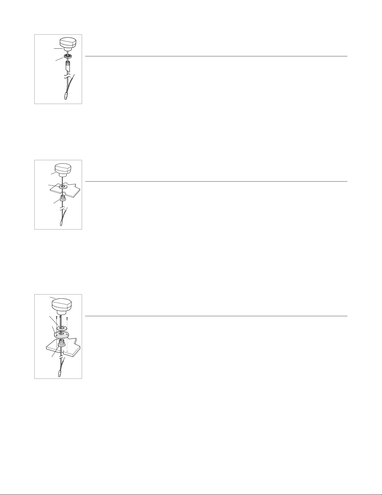
Stem Mount
(Existing Stem with 1" - 14 Thread)
Follow these steps to stem mount the WSL antenna (stem not included):
1. Determine the best mounting location, then make sure that there is sufficient cable to route to
the Fishfinder. Mark the mounting location, then drill a
⁵₈
" (15 mm) hole.
2. Place stem over
⁵₈
" (15 mm) hole and mount with screws provided with stem.
3. Place lock nut on stem, thread down at least half way.
4. Route the WSL cable through the stem, then continue routing it through the deck surface to the control head.
5. Thread the WSL onto the stem. Tighten lock nut with crescent wrench to secure the WSL antenna.
Under Location Access with Thin Deck
(Less Than
³₈
" or 10 mm)
Follow these steps to mount the WSL antenna onto a deck that is thinner than
³₈
" (10 mm), routing the
cable down through the mounting surface:
1. Determine the best mounting location, then make sure there is sufficient cable to route to the
Fishfinder.
2. Mark mounting location and drill a 1" (25 mm) hole.
3. Insert mounting bolt through 1" (25 mm) hole from lower side of the mounting surface.
4. Place the gasket over the mounting bolt, then route the WSL cable down through the mounting bolt to the control head.
5. Position the WSL over the mounting bolt, then secure in place.
Under Location Access with Thick Deck
(More Than
³₈
" or 10 mm)
Follow these steps to mount the WSL antenna onto a deck that is thicker than
³₈
" (10 mm), routing the
cable down through the mounting surface:
1. Determine the best mounting location, then make sure that there is sufficient cable to route to
the fishfinder.
2. Place the mounting flange over your mounting location and mark the following locations for drill
holes: through the center of the mounting flange for the WSL cable, and through the
three mounting holes for the mounting flange.
3. Remove the mounting flange and drill a
⁵₈
" (15 mm) hole at the center location and drill the three
⁹₆₄
" (3.5 mm) mounting holes.
4. Assemble the mounting flange, mounting bolt, and gasket, then place over the
⁵₈
" (15 mm) center hole. Secure in
place with three #8 x
⁵₈
" flat head screws.
5. Position the WSL over the center hole and route the cable through the center hole, then secure in place.
6. Route the WSL cable to the control head.
WSL
Antenna
Gasket
Mounting
Flange
Mounting
Bolt
WSL
Antenna
Mounting
Bolt
Gasket
WSL
Antenna
Lock Nut
Page 5

Deck Mount - Cable Side, No Access Underneath
Follow these steps to deck mount the WSL antenna in a situation where you must route
the cable to the side because there is no space for a cable underneath the mounting location:
1. Determine the best mounting location, then make sure that there is sufficient cable
to route to the fishfinder.
2. Place the mounting flange over the mounting location and mark through the three
mounting holes for drilling.
3. Remove the mounting flange and drill holes using a
⁹₆₄
" (3.5 mm) drill bit.
4. Break out the marked tab on the bottom side, outer rim of the mounting flange.
5. Pre-assemble the mounting flange, mounting bolt, and gasket with the WSL, routing the cable through all components; tighten the WSL antenna until its base is in contact with the gasket, making certain that the notch in the
mounting bolt is aligned with the breakout tab in the mounting flange.
6. Position the WSL in the mounting location and secure the flange with three #8 x
⁵₈
" flat head screws. To access all
screws you will need to rotate the WSL. When finished, secure tightly.
7. Determine a hole location where access for cable routing is available.
8. Drill a
⁵₈
" (15 mm) hole at this location and route the cable through the hole.
9. Install the escutcheon plate at this location with two #8 x
⁵₈
" flat head screws.
10. Route the cable to the control head.
Connecting the WSL to the Control Head
1a. Attach the WSL to your control head COM port using the longer, male end of the cable from the WSL.
Or…
1b. If you are already using another accessory plugged into the COM connector, you can attach the WSL to the already-
attached accessory's extra cable.
Or…
1c. If you have a GPS receiver plugged into the control head, you must use the AS-YC ("Y") cable that was included in
your GPS Hardware Kit so that you can use both the accessories and your GPS receiver at the same time. Attach the
COM connector of the "Y" cable directly to your control head COM port. Attach the GPS receiver to the NMEA-COM
connector of the "Y" cable and re-connect your accessories to the ACCY-COM connector of the "Y" cable.
2. Power up the control head (see your control head Operation Manual for details).
3. When the control head detects the WSL, the SmartCast WSL View will be added automatically to the VIEW key function. A SmartCast WSL menu choice will be added to the Accessory menu tab, and the WSL X-Press menu will also
be added automatically to the Menu system.
WSL
Antenna
Mounting
Flange
Mounting Bolt
Escutcheon Plate
Gasket
Page 6

Attaching the RSS
The line coming from your reel can be tied off to the front hole in the Remote Sonar Sensor (RSS). If you wish to also use
the RSS as a conventional float, use the second hole to attach your hook using a lighter weight line. A snag will break the
lighter line if you have to break free. Slip line techniques are not recommended because of the higher risk of losing the RSS.
If you do use the slip line method, use a lighter weight line after the lower stop, enabling retrieval of the RSS if the lower
line with hook breaks away.
CAUTION: You will increase the possibility of breaking your line if you use light test pound line on your reel. The RSS is positively buoyant (is
buoyant under its own weight plus 0.2 ounces or 5.7 g of bait and lead weight.) The maximum amount of weight for any attachment to
the RSS is approximately
¹²₆₄
to
¹³₆₄
ounces (5.3 g to 5.8 g), and includes the combined weight of any hook, line, weight, swivel/snap swivel
and bait that is attached to the RSS. The RSS itself weighs 1 ounce (28 g), and therefore light test line might break.
RSS Power and Battery Life
The Remote Sonar Sensor (RSS) has a separate, non-replaceable lithium battery that has a shelf life of three years and will
last for approximately 400 hours of in-water use. Discard the used RSS in compliance with local laws as you would any electronic component or battery.
The RSS has contacts that perceive when the device is immersed in the water. These contacts turn on the Sonar
Transmitter/Receiver and begin transmitting the sonar information via RF to the WSL. The RSS automatically stops using power
a few seconds after being pulled out of the water.
WARNING! Store the RSS in a dry, non-metallic container, such as a tackle box, in a separate compartment, and isolated from any metallic
devices when not in use to conserve power. Never place the RSS in a wet area of a boat or on a metal surface when not in use as this could
turn it on and shorten its usable life.
NOTE: If the RSS was used in salt water, rinse it with fresh water before storing it.
Use a heavy test line, standard knots, and tackle such as a swivel.
Handle the RSS by the antenna tower
when it has been in water.
The second leader hole is for using the RSS as a float. Connect a lighter
weight hook line to this hole. Do not over-weight the hook line as this will
submerge the RSS, causing signal loss.
Page 7

Operating the WSL Accessory
When the WSL Accessory is attached to the control head, a SmartCast WSL View is added to the control head view rotation.
When you press the VIEW key repeatedly, views are displayed cyclically. Any of the views, including the SmartCast WSL
View, can be removed or added to the rotation list using the Select Views menu choice from the Setup Menu when in
Advanced Mode (see your control head Operation Manual for more information).
The following graphic shows the SmartCast WSL View:
NOTE: When the RSS is in the water within line-of-site of the WSL, the SmartCast WSL View will display sonar returns from the RSS. When
the RSS is not in the water or reception is being blocked, the "SmartCast WSL signal not detected" message will be displayed.
The SmartCast WSL View displays underwater sonar information in an easy to understand format. The top of the display
corresponds to the water surface, and the bottom of the display corresponds to the selected Depth Range (see Depth
Range). The display varies as the area under the RSS changes. Reeling in the RSS at a slow and steady rate will allow you to
graph the bottom for structure, detail and fish. Digital readouts provide precise information for bottom contour, depth and
fish locations below the RSS.
Underwater conditions vary greatly, so some experience and interpretation is needed to realize all the benefits of the WSL
Accessory - use the picture above as a guide to the most common conditions and practice using the RSS over known bottom types.
WSL PIP View
The Picture in Picture (PIP) WSL View will appear if the PIP menu choice has been either turned "on" or set to "auto" from
the SmartCast WSL menu (
sseeee WWSSLL AAcccceessssoorryy SSuubbmmeennuu
) and will only appear after the RSS has been cast into the water. The
PIP View is superimposed on every view in the view rotation with the exception of the WSL full screen view. Use the 4-Way
Cursor Control key to re-position the PIP view on the display. The following graphic shows the WSL PIP View superimposed
on the Sonar View:
NOTE: When the RSS is in the water within line-of-site of the WSL, the PIP View will display sonar returns from the RSS. When the RSS is not
in the water or reception is being blocked, the “SmartCast WSL signal not detected” message will be displayed.
Depth
Fish
Bottom
Contour
Upper
Depth Range
Lower
Depth Range
Depth
Bottom
Fish Icon
Lower Depth
Range
Upper Depth
Range
Page 8

WSL X-Press™ Menu
When the SmartCast WSL View is displayed, pressing the MENU key once will display the WSL X-Press menu. The WSL XPress menu represents the settings most frequently used to optimize the WSL performance.
NOTE: The WSL X-Press Menu can only be accessed from the SmartCast WSL Full Screen view. It is not available in the PIP view.
WWSSLL SSeennssiittiivviittyy
- Select a higher number to show weaker sonar returns on the display, or a lower number to remove clutter from the display. Adjusting Sensitivity also affects how sonar returns are identified as Fish ID Symbols - more fish will
be detected at the highest setting of 5, fewer at the lowest setting of 1. (1, 2, 3, 4, 5, Default = 3)
WSL Lower Range: WSL Lower Range sets the deepest depth range that will be displayed. Automatic is the default setting. When
in automatic mode, the lower range will be adjusted by the unit to follow the bottom. Selecting a specific setting locks the depth
range into Manual mode. Use WSL Lower Range to view a specific depth range manually resulting in a greater level of detail for the
selected depth range to be shown on the display. M will be displayed in the lower right corner of the display to indicate the unit is
in Manual mode. (Auto, 10 - 100 Ft, Default = Auto)
NOTE: In manual operation, if the water depth is greater than the depth range setting, the bottom will not be visible on-screen. Select AUTO
to return to automatic operation.
Depth scale changes or signal loss will cause lines with missing detail and/or abrupt changes in the graphed bottom. When
the Depth Range is set to AUTO, the depth is set to keep the bottom in the lower third of the screen. The screen image jump
shown here is due to an automatic change in depth. New returns graphed at a different scale will not match up with the
historic data already graphed at a higher or lower scale. Vertical lines can also occur as the radio signal from the RSS is lost
and then regained in rough water conditions.
Page 9

WSL Accessory Submenu
When the WSL Accessory is attached to the control head, the Accessory menu tab in the Main Menu System will contain
an additional SmartCast WSL menu choice which, when selected, leads to the SmartCast WSL Accessory Submenu.
Press the MENU key twice to access the Main Menu tab choices. Use the 4-Way Cursor Control key to select the Accessory
tab, and then scroll down to select the SmartCast WSL menu choice - use the RIGHT Cursor Control key to enter the WSL
Accessory Submenu.
PIP (Picture in Picture) Setting - This menu choice sets whether the PIP view is Off, On or set to Auto.
When set to
OOffff
, the PIP View is not available in the view rotation.
When set to
OOnn
, the PIP View will be superimposed on all views (with the exception of the full screen WSL View) the first
time that the RSS is cast into the water. When the RSS is out of the water or if the signal reception is being blocked, the
message "SmartCast WSL signal not detected" will appear. The PIP View can be removed from the view rotation by pressing the EXIT key. The next time the RSS enters the water, the PIP View will be displayed again.
When set to
AAuuttoo
, the PIP View will be superimposed on all views (with the exception of the full screen WSL view) the first
time that the RSS is cast into the water. When the RSS is out of the water or if the signal reception is being blocked, the
message "SmartCast WSL signal not detected" will flash on the PIP View and the PIP View will then be removed automatically from the view rotation. The next time you cast the RSS back into the water, or if signal reception is regained, the PIP
View will be displayed automatically. (Off, On, Auto, Default = Off)
Channel Select: This menu choice should be set to A for the Channel A RSS that is shipped with your WSL Accessory. If you
buy a replacement RSS that is hard-wired as a Channel B, then you must change this setting to B. Select either A or B to
match your RSS. See Channel A and B RSS Units. (Channel A or Channel B, Default = Channel A)
Accessory Menu:
with Wireless Sonar
Link added
WSL Accessory Submenu
Page 10

Channel A and B RSS Units
There are two versions of the RSS that are available at your local tackle dealer, major outdoor retailers, or at www.humminbird.com: Channel A and Channel B.
The Channel A RSS unit comes standard with the WSL Accessory. You also have the option to purchase additional Channel
A or Channel B RSS units. When using the A or B version of the RSS, make sure to select the appropriate channel in the
Channel menu choice from the WSL Accessory Submenu on the control head.
The A&B Channel Option gives you the flexibility to use a different type of RSS than the one you are currently using if
another angler is using a SmartCast product within 100 feet (30 m) of your RSS. Two Channel A or two Channel B RSS units
in the water within 100 feet (30 m) of the display will cause RF interference that prevents the product from functioning
properly, resulting in fluctuating depth readings and excessive clutter on the screen. If you use a Channel B RSS while
another angler is using a Channel A RSS or vice versa, the interference will be reduced but not completely eliminated.
NOTE: RSS units, regardless of Channel, either in close proximity to each other or to other sonar devices (closer than 40 feet or 12 m) can
also experience or cause sonar interference, which may result in erratic depth readings.
Maintenance
Your WSL Accessory is designed to provide years of trouble-free operation with virtually no maintenance. Follow these simple procedures to ensure your WSL continues to deliver top performance.
If the WSL comes into contact with salt spray, wipe the affected surfaces with a cloth dampened with fresh water.
After using the RSS in salt water, wipe the affected surfaces with a cloth dampened with fresh water. The RSS Wet Switch™
pins must be rinsed with fresh water after exposure to salt water to prevent corrosion.
If your RSS remains out of the water for a long period of time, it may take some time to wet it when returned to the water.
Small air bubbles can cling to the surface of the RSS and interfere with proper operation. Wipe the face of the RSS with a
wet cloth to remove them.
If sonar performance becomes weak (i.e., there are bottom gaps or "0" depth readings) the bottom of the RSS
needs to be cleaned with a drop or two of a 5 to 10 percent solution of liquid dishwashing detergent and water. Use
approximately one tablespoon (15 ml) detergent to 8 ounces (237 ml) of water to remove oils from the face of the
RSS, then wipe with a damp cloth.
Never leave the WSL or RSS in a closed car or trunk - the extremely high temperatures generated in hot weather can damage the electronics.
Page 11

Troubleshooting
Do not attempt to repair the RSS or the WSL yourself. There are no user serviceable parts inside, and special tools and techniques are required for assembly to ensure the waterproof integrity of the housings. Repairs should be performed only by
authorized Humminbird technicians.
Many requests for repair received by Humminbird involve units that do not actually need repair. These units are returned
"no problem found." If you have a problem with your RSS or WSL, use the following troubleshooting guide before calling
the Customer Resource Center or sending your unit in for repair.
1. The control head does not display the WSL View, or any of the RSS or WSL menu choices:
First, verify that you have the correct version of software running in your control head. You should have version 2.100 or
higher. If you do not, go to the procedure described under Determining the Software Version in the Control Head and
upload the correct version of software.
Second, make sure the cable connecting the WSL unit to the control head is installed and connected correctly. If the WSL
View still does not display, make sure that the Select Views menu selection (Setup menu, Advanced user mode) is set to
display the WSL View.
Third, the battery on your RSS may have died. You will need to replace the RSS with a new one, as the battery is non-replaceable.
2. The Wireless Sonar Link loses signal (the Loss of Signal message) appears on the control head screen:
RSS battery voltage is below a given threshold, and the battery may even be dead. If the WSL is not able to get an RF signal from the RSS, the control head WSL View display will stop updating (the screen will freeze) and the WSL Loss of Signal
message ("SmartCast WSL signal not detected") will be displayed after several seconds. Whenever reception is lost or the
RSS emerges from the water for more than a few seconds, the WSL Loss of Signal message will be displayed until the RSS
is placed back in the water and reception is regained.
• The WSL system is a line-of-sight wireless product. If objects are placed between the RSS and the WSL, the reception may be lost.
• The RSS depth range is 2 to 100 feet (0.6 to 30 meters). Erratic readings may occur in water that is shallower than 2 feet
(0.6 m). In addition, because of the nature of sonar, this product is not intended for use in swimming pools or small,
enclosed bodies of water.
• Reeling in the RSS too fast can cause loss of signal and the screen will freeze
• Check the buoyant balance between the RSS and your tackle; over 0.2 ounce (5.7 g) will submerge the RSS, causing signal loss.
• The RSS may not obtain its maximum RF distance of 100 feet (30 m) unless the water is smooth. Waves or chop may reduce
the RF range significantly.
3. When in very shallow water, I get gaps in the bottom reading and inconsistent digital depth indication.
The RSS will work reliably in water 2 feet (0.6 m) or deeper. The depth is measured from the RSS. A transmitter (RSS) to
receiver (Antenna) distance of greater than 100 feet (30 m) may result in signal loss. Excessively rough water may cause
the RSS to submerge, again losing contact.
Page 12

4. The WSL View shows many black dots at high sensitivity settings.
You are seeing noise or interference caused by one of several sources. Noise can be caused by other electronic devices. Turn
off any nearby electronics and see if the problem goes away. Other sonar devices or any electronic device operating in the
900 mHz range (in the 400 mHz for International versions) could cause interference with your RSS.
5. The WSL View shows fluctuating depth readings and excessive clutter, including vertical bars that may be drawn on
top of fish icons.
The WSL system comes with the capability to receive separate signals from a Channel A RSS or a Channel B RSS. Two A- or
B-type RSS units used simultaneously, as well as one A- and one B-type RSS unit used simultaneously, can cause RF interference between each other.
6. The screen jumps and the bottom has an abrupt change; sometimes a vertical line is missing or a black line from top
to bottom is displayed.
This screen image jump is due to an automatic change in depth. New returns graphed at a different scale will not match
up with the historic data already graphed at a higher or lower scale. Vertical lines can also occur as the radio signal from
the RSS is lost and then regained in rough water conditions.
Page 13

Specifications
WSL Specifica
tions
Power Requirement ............................................................................................................................ Provided by the control head
Integral Cabling ...................................................................................................................................................... 20 feet (6 m) cable
RSS Specifications
Internal Lithium Battery.............................................................................................. One non-replaceable RSS Lithium battery
Battery Expected Life.................................................................................. 3 years (approximately 400 hours of in-water use)
Depth Capability .................................................................................................................................. 2 - 100 feet (0.6 - 30 meters)
Sonar Coverage .................................................................................................................................................................. 90° @-10 dB*
Sonar Operating Frequency .................................................................................................................................................... 120 kHz
Operational Radio Frequency.......................................................................................... 916.5 mHz (International 433.92 mHz)
Operational Range........................................................................................................................................................ 100 feet (30 m)
*Area of bottom coverage equals twice the current depth.
Contact Humminbird
Your Humminbird accessory is designed for trouble-free operation
and is backed by a one-year warranty. If you have any questions, contact our
Humminbird Customer Resource Center:
By Telephone (Monday - Friday 8:00 a.m. to 4:30 p.m. Central Standard Time):
334-687-0503
By e-mail (typically we respond to your e-mail within three business days):
custserv@techsonic.com
For direct shipping, our address is:
Techsonic Industries, Inc.
Service Department
108 Maple Lane
Eufaula, AL 36027 USA
Techsonic Industries
This device complies with Part 15 of the FCC Rules.
Operation is subject to the following two conditions:
(1) This device may not cause harmful interference and;
(2) This device must accept any interference received, including interference that may cause unde-
sired operation.
CAUTION: Changes or modifications not expressly approved by Techsonic Industries could void the users authority to
operate the device.
FCC ID: ICLSMC1
 Loading...