

Page 1
1
TRANSDUCER SELECTOR
B
A
T
R
A
N
S
D
U
C
E
R
S
E
L
E
C
T
O
R
A
B
Transducer Switch
Thank You
Thank you for choosing Humminbird®, America's #1 name in fishfinders. Humminbird® has built its reputation by
designing and manufacturing top-quality, thoroughly reliable marine equipment. Genuine Humminbird® accessories
offer the opportunity to upgrade and expand the capabilities of your Humminbird® product.
Your Humminbird® accessory is designed for trouble-free use in even the harshest marine environment.
In the unlikely event that your Humminbird® accessory does require repairs, we offer an exclusive Service Policy - free
of charge during the first year after purchase, and available at a reasonable rate after the one-year period. For
complete details, see the Warranty section included in this manual.
Contact our Customer Resource Center at 1-800-633-1468 or visit our web site at www.humminbird.com.
Installation Overview
Following are instructions for the installation of this accessory. Before you start installation, we encourage you to read
these instructions carefully in order to get the full benefit from your Humminbird® accessory.
If you find that any items are missing from your installation kit, call our Customer Resource Center at 1-800-633-1468
or visit our web site at www.humminbird.com.
The Transducer Switch comes with all the necessary hardware to allow you to connect your control head to two
transducers. The transducers may be the same type of transducer with different mounting locations, or you can
maximize your unit’s performance by using two different transducers. The switch is intended for installation on the
console, and will work well on almost any boat.
530521-2_C
In addition to the hardware supplied with your Transducer Switch, you will need a hand drill with various size bits, a
Phillips screwdriver, and an adjustable wrench.
Before installing the Transducer Switch, gather all the parts you will need, and make sure that the planned location of
the Transducer Switch will allow you to connect the two transducers to your control head.
Installation
Perform the procedures in the following sections to install the Transducer Switch on your boat.
1.Locating the Transducer Switch Mounting Position
To determine where to mount the Transducer Switch, make sure that it will be positioned near your control head on
the console of the boat, within reach of the cables for both transducers.
After you have determined the best mounting location for your Transducer Switch, proceed with the following
instructions.
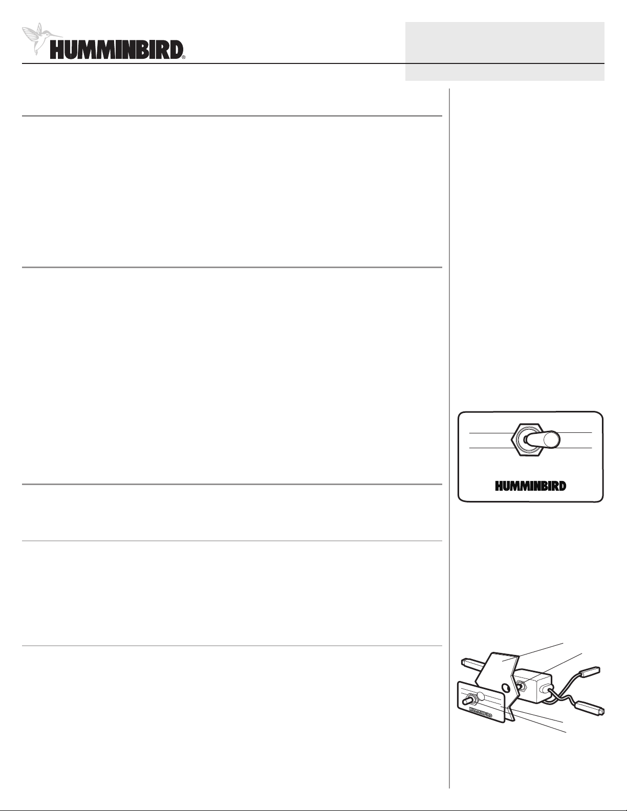
2.Attaching the Transducer Switch
1. Remove the switch plate from the switch assembly.
2. Using the switch plate as a template, mark the location of the hole with a pencil or punch.
Transducer Switch With Cover
Switch Assembly
Boat Console
Switch
3. Drill a 1/2” mounting hole at the desired location.
4. Test the fit of the Transducer Switch in the mounting location.
5. Remove the paper from the back of the switch cover to expose the adhesive backing and press the switch plate
onto the mounting location.
Switch Cover
Rubber Boot
© 2008 Humminbird®, Eufaula AL, USA.
All rights reserved.
Page 2
2
T
RANSDUCERSELECTOR
B
A
Transducer Switch
6. Insert the threaded shaft of the switch through the hole and hold it in place with one hand, making sure that the
pivot of the switch is aligned with the letters A and B.
7. Push the rubber boot over the top of the switch and tighten onto the shaft.
8. Fully tighten the nut using an adjustable wrench.
CAUTION: Use care when tightening the nut to avoid damaging the rubber boot.
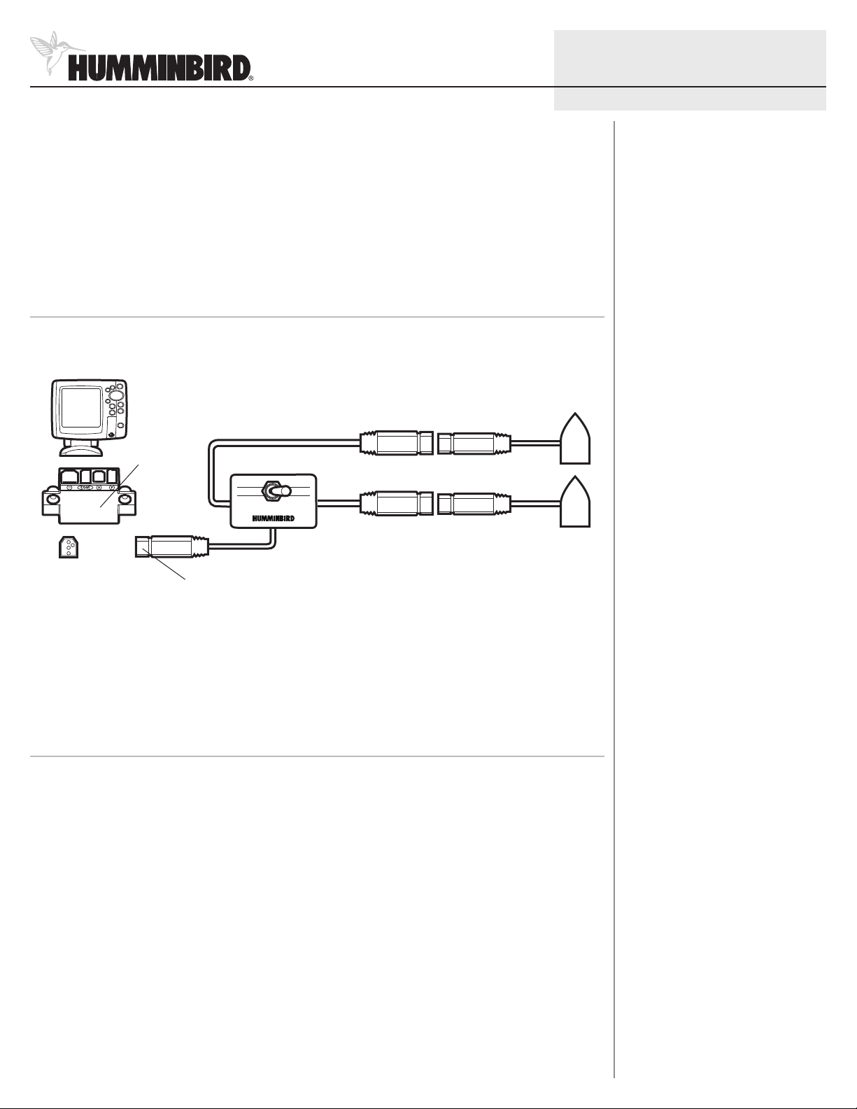
3.Connecting the Transducers to the Switch and the Control Head
1. Connect the two transducers to the Transducer Switch, referring to the illustration for guidance.
Connecting Two Transducers to the Switch and Control Head
Control head
Connector
Holder
TS2 W Switch
Standard Transducer
530521-2_C
Second Transducer
Route connector to the unit
2. Remove the connector holder from your control head and insert the cable connector from the Transducer Switch
into the connector holder.
CAUTION: The slot for the connector is keyed to prevent reversed installation, so do not force the connector into the holder.
See the Installation section of your operations manual for additional information.
4.Connecting the Cable
CAUTION! Do not cut or shorten the transducer cables, and try not to damage the cable insulation. Route the cable as far
as possible from any VHF radio antenna cables or tachometer cables to reduce the possibility of interference. If the cable is
too short, extension cables are available to extend the transducer cable up to a total of 50'. For assistance, contact the
Customer Resource Center at www.humminbird.com or call 1-800-633-1468 for more information.
1. Insert the Transducer Switch cable connector into the appropriate slots of the connector holder. The cable
connectors are labeled, and there are corresponding labels on the connector holder on the rear of your control
head. The slots are keyed to prevent reversed installation, so be careful not to force the connector into the holder.
Your control head is now ready for operation.
© 2008 Humminbird®, Eufaula AL, USA.
All rights reserved.
Page 3

3
Transducer Switch
Maintenance
If your boat remains in the water for long periods of time, algae and other
marine growth can reduce the effectiveness of the transducer. Periodically
clean the face of the transducer with hot water.
If your boat remains out of the water for a long period of time, it may take
some time to wet the transducer after it is returned to the water. Small air
bubbles can cling to the surface of the transducer and interfere with proper
operation. These bubbles will dissipate with time, or you may wipe the face of
the transducer with your fingers after the transducer is in the water.
1-Year Limited Warranty
We warrant the original retail purchaser that products made by Humminbird®
have been manufactured free from defects in materials and workmanship.
This warranty is effective for one year from the date of original retail
purchase. Humminbird® products found to be defective and covered by this
warranty will be replaced or repaired free of charge at Humminbird® option
and returned to the customer freight prepaid. Humminbird® sole responsibility
under this warranty is limited to the repair or replacement of a product that
has been deemed defective by Humminbird®. Humminbird® is not responsible
for charges connected with the removal of such product or reinstallation of
replaced or repaired parts.
This warranty does not apply to a product that has been:
• Improperly installed;
• Used in an installation other than that recommended in the product
installation and operation instructions;
• Damaged or has failed because of an accident or abnormal operation;
• Repaired or modified by entities other than Humminbird®.
Please retain your original receipt as a proof of the purchase date. This will be
required for in-warranty service.
530521-2_C
Humminbird® Service Policy
Even though you'll probably never need to take advantage of our incredible
service policy, it's good to know that we back our products this confidently.
We do it because you deserve the best. We will make every effort to repair
your unit within three business days from the receipt of your unit at our
factory. This does not include shipping time to and from our factory. Units
received on Friday are typically shipped by the following Wednesday, units
received Monday are typically shipped by Thursday, etc.
All repair work is performed by factory-trained technicians to meet exacting
factory specifications. Factory-serviced units go through the same rigorous
testing and quality control inspections as new production units.
After the original warranty period, a standard flat rate service charge will
be assessed for each repair (physical damage and missing parts are not
included). Any repairs made after the original warranty will be warranted
for an additional 90 days after service has been performed by our factory
technicians. You can contact our Customer Resource Center or visit our
web site to verify the flat rate repair fee for your product (visit the Product
Support section):
http://www.humminbird.com
We reserve the right to deem any product unserviceable when replacement
parts are no longer available or impossible to obtain. This Service Policy is
valid in the United States only. This applies only to Humminbird® products
returned to our factory in Eufaula, Alabama. This Service Policy is subject to
change without notice.
DOMESTIC (USA) CUSTOMERS:
PLEASE DO NOT RETURN THIS PRODUCT TO STORE FOR SERVICE
For all technical issues please call 1-800-633-1468
or visit www.humminbird.com,
Ple
ase reference product serial number and
model number when contacting Humminbird®.
click SUPPORT.
THIS WARRANTY IS EXPRESSLY IN LIEU OF ANY OTHER WARRANTIES,
OBLIGATIONS OR LIABILITIES ON THE PART OF HUMMINBIRD® AND WILL BE
THE CUSTOMER'S EXCLUSIVE REMEDY, EXCEPT FOR ANY APPLICABLE
IMPLIED WARRANTIES UNDER STATE LAW WHICH ARE HEREBY LIMITED IN
DURATION TO ONE YEAR FROM THE DATE OF ORIGINAL PURCHASE. IN NO
EVENT WILL HUMMINBIRD® BE LIABLE FOR ANY INCIDENTAL OR
CONSEQUENTIAL DAMAGES FOR BREACH OF ANY EXPRESS OR IMPLIED
WARRANTY RELATING TO THE PRODUCTS.
Some states do not allow limitations on an implied warranty, or the exclusion
of incidental or consequential damages, so the above exclusions may not
apply to you. You may also have other rights, which vary from state to state.
© 2008 Humminbird®, Eufaula AL, USA.
All rights reserved.
Page 4

4
Transducer Switch
Returning Your Unit for Service
Before sending your unit in for repair, please contact the factory, either by
phone or by email, to obtain a Repair Authorization Number for your unit.
NOTE: Please do not return your Humminbird® to the store for service.
Please have your product model name and serial number available before
calling the factory. If you contact the factory by e-mail, please include your
product model name and serial number in the e-mail, and use Request for
Repair Authorization Number for your e-mail subject header. You should
include your Repair Authorization Number in all subsequent communications
about your unit.
For IN-WARRANTY service, complete the following steps:
• Obtain a Repair Authorization Number from the Humminbird® Customer
Resource Center.
• Tag product with your name, street address, phone number and your
assigned Repair Authorization Number.
• Include a brief written description of the problem.
530521-2_C
Contact Humminbird®
Contact the Humminbird® Customer Resource Center
in any of the following ways:
By Telephone
(Monday - Friday 8:00 a.m. to 4:30 p.m. Central Standard Time):
1-800-633-1468
By e-mail
(typically we respond to your e-mail within three business days):
cservice@johnsonoutdoors.com
For direct shipping, our address is:
Humminbird
Service Department
678 Humminbird Lane
Eufaula, AL 36027 USA
• Include a copy of your receipt (to show proof and date of purchase).
• Return product freight prepaid to Humminbird®, using an insured carrier
with delivery confirmation.
For OUT-OF-WARRANTY service, complete the following steps:
• Obtain a Repair Authorization Number from the Humminbird® Customer
Resource Center.
• Include payment in the form of credit card number and expiration date,
money order or personal check. Please do not send cash.
• Tag product with your name, street address, phone number and your
assigned Repair Authorization Number.
• Include a brief written description of the problem.
• Return product freight prepaid to Humminbird®, using an insured carrier
with delivery confirmation.
© 2008 Humminbird®, Eufaula AL, USA.
All rights reserved.
 Loading...