

Page 1
1
Trolling Motor Mounted Transducer
Thank You
Thank you for choosing Humminbird®, America's #1 name in fishfinders. Humminbird® has built its reputation by
esigning and manufacturing top-quality, thoroughly reliable marine equipment. Genuine Humminbird® accessories
d
offer the opportunity to upgrade and expand the capabilities of your Humminbird® product.
NOTE: Your transducer may not look exactly like the transducer shown in the illustrations, but it will mount in exactly the
same way.
Your Humminbird® accessory is designed for trouble-free use in even the harshest marine environment. In the unlikely
event that your Humminbird® accessory does require repairs, we offer an exclusive Service Policy - free of charge
during the first year after purchase, and available at a reasonable rate after the one-year period. For complete details,
see the Warranty section included in this manual.
Contact our Customer Resource Center at either 1-800-633-1468 or visit our Web site at humminbird.com.
Installation Overview
Following are instructions for the installation of this accessory. Before you start installation, we encourage you to read
these instructions carefully in order to get the full benefit from your Humminbird® accessory.
If you find that any items are missing from your installation kit, call our Customer Resource Center at 1-800-633-1468
or visit our Web site at humminbird.com.
In addition to the hardware supplied with your transducer, you will need various hand tools.
530511-3_A
Trolling Motor Mount Installation
Attaching the Transducer to
the Trolling Motor
NOTE: The transducers shown below
have no directional bias.
Installation
The trolling motor transducer is designed to mount on the trolling motor of your boat. All hardware needed for
installation and operation of this Humminbird® accessory is either included with this accessory or came with your
original transducer. The trolling motor mounted transducer allows you to gather sonar information from the point on
the boat closest to where you are fishing. It is important that you properly orient the transducer housing in the
direction of travel of the trolling motor, to ensure an accurate depiction of the terrain under your boat.
The trolling motor mounted transducer will fit any standard trolling motor housing. Some users install this transducer
in conjunction with a switch so that the standard transducer can be used for high-speed operation, and the trolling
motor transducer can be used while trolling.
1. Attaching the Transducer
WARNING! Before attaching the transducer to the trolling motor, confirm that the motor is disconnected from all sources of
electrical power.
CAUTION! Before attaching the transducer to the trolling motor, make sure the trolling motor is properly secured to the boat
and will not shift during transducer installation.
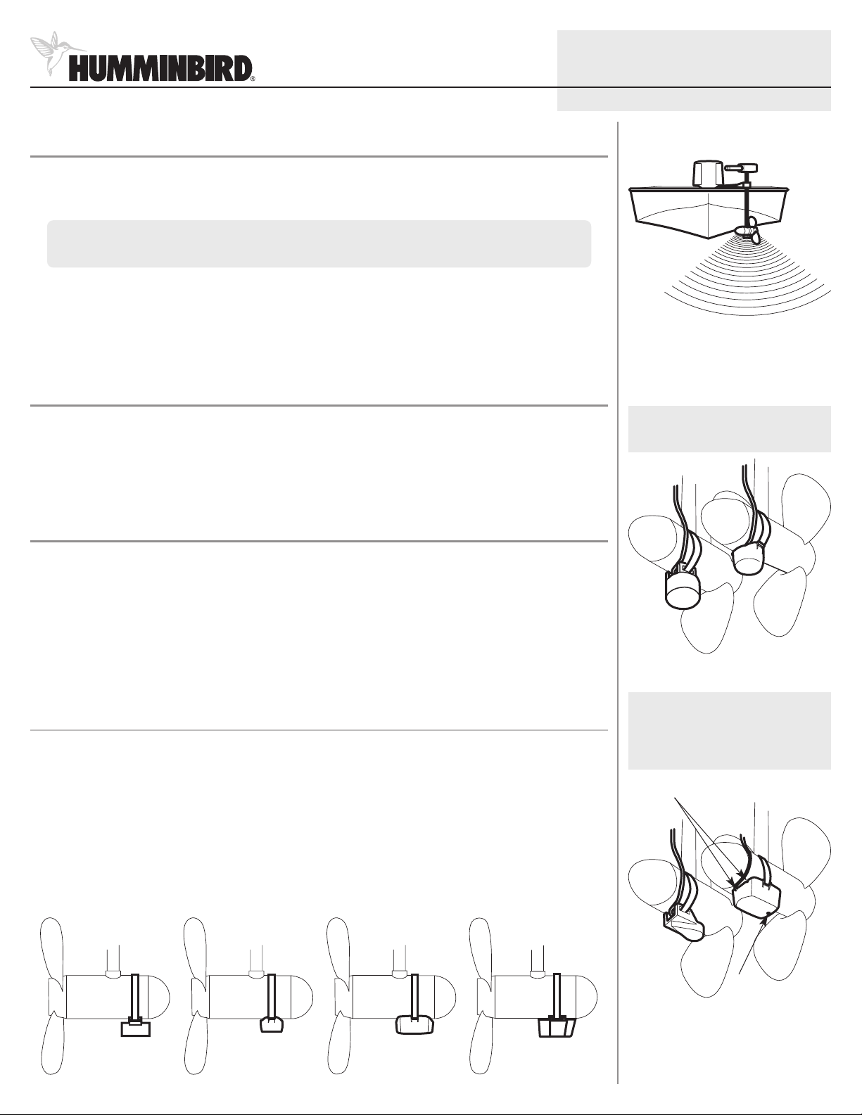
1. Position the transducer on the underside of the motor housing. Refer to the illustration that most resembles your
accessory, noting any requirements for directional bias.
NOTE: Round, circular-bottomed transducers have no directional bias, and therefore orientation of these types of
transducers is not as important. Rounded rectangular transducers, however, do have a directional bias, and must be
installed as shown in the illustration.
Side View of the Transducer
NOTE: The transducers shown below
have a directional bias, and therefore
need to be oriented according to
the illustration below.
Cable slots
Transducer should be mounted forward of the motor shaft. Styles of transducer may differ from illustration.
Temp
probe
© 2011 Humminbird®, Eufaula AL, USA.
All rights reserved.
Page 2
2
Trolling Motor Mounted Transducer
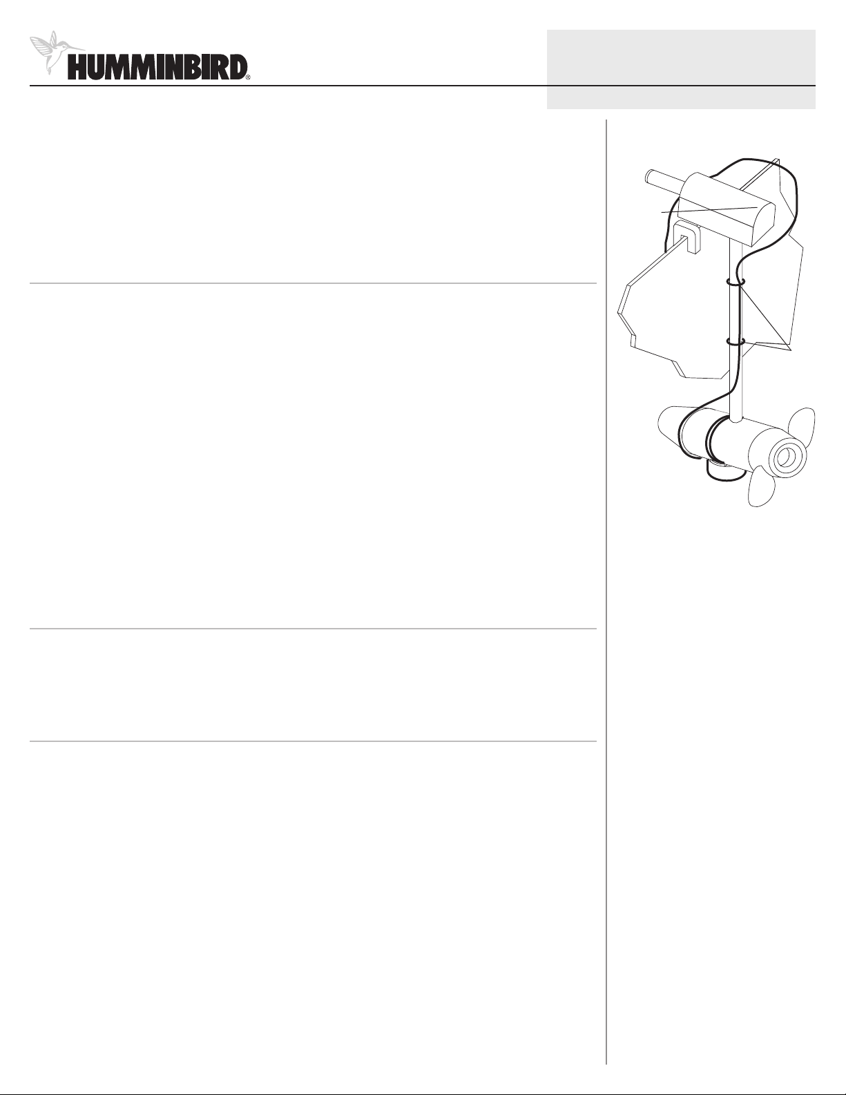
2. Insert the hose clamp through both openings on the top of the transducer and pull the two ends up around the
motor housing. As you tighten the hose clamp, check to make sure that the transducer is properly aligned with
the motor housing.
3. After tightening the hose clamp, make sure that the transducer is securely attached to the motor housing and
will not slip off while in operation.
2.Routing the Cable
The transducer cable has a low profile connector which must be routed to the point where the control head is
mounted. There are several ways to route the transducer cable to the area where the control head will be installed.
NOTE: Your boat may have a pre-existing wiring channel or conduit that you can use for the transducer cable.
1. Unplug the other end of the transducer cable from the control head. Make sure that the cable is long enough to
accommodate the planned route.
CAUTION! Do not cut or shorten the transducer cable, and try not to damage the cable insulation. Route the cable as far as
possible from any VHF radio antenna cables or tachometer cables to reduce the possibility of interference. If the cable is too
short, extension cables are available to extend the transducer cable up to a total of 50' (15 m). For assistance, contact the
Customer Resource Center at humminbird.com or call 1-800-633-1468 for more information.
2. Routethe transducer cable around the side of the motor housingand secure it to the motorshaft using the plastic
cable ties which have been provided.
530511-3_A
Routing the Cable
Slack in
Cable
Cable
Ties
NOTE: As you route the cable from the trolling motor to the boat, be sure to leave sufficient slack in the cable to allow for
full movement and retraction of the trolling motor during normal operation.
3. Route the transducer cable to the control head.
3.Connecting the Cable
Insert the transducer cable into the appropriate terminal slot. The cable connectors are labeled, and there are
corresponding labels on the cable holder on the rear of the control head. The slots are keyed to prevent reversed
installation, so be careful not to force the connector into the holder.
4.Test and Finish the Installation
When you have installed both the control head and the trolling motor transducer, and have routed all the cables, you
must perform a final test to verify installation. Testing should be performed with the boat in the water, although you
can initially confirm basic operation with the boat out of the water.
NOTE: Make sure the trolling motor is re-connected to the power source before performing this procedure.
1. Press POWER once to turn the control head on. If the unit does not power-up, make sure that the connector
holder is fully seated in the receptacle and that power is available.
2. If all connections are correct and power is available, the Humminbird® control head will enter Normal operation.
NOTE: The transducer must be submerged in water for reliable transducer detection.
3. Make sure that the boat is in water greater than 2' but less than the depth capability of the unit, and that the
transducer is fully submerged, since the sonar signal cannot pass through air. If the bottom is visible on-screen
with a digital depth readout, the unit is working properly.
Your control head is now ready for operation.
© 2011 Humminbird®, Eufaula AL, USA.
All rights reserved.
Page 3

3
Trolling Motor Mounted Transducer
Maintenance
If your boat remains in the water for long periods of time, algae and other
marine growth can reduce the effectiveness of the transducer. Periodically
lean the face of the transducer with hot water.
c
If your boat remains out of the water for a long period of time, it may take
some time to wet the transducer after it is returned to the water. Small air
bubbles can cling to the surface of the transducer and interfere with proper
operation. These bubbles will dissipate with time, or you may wipe the face of
the transducer with your fingers after the transducer is in the water.
1-Year Limited Warranty
We warrant the original retail purchaser that products made by Humminbird®
have been manufactured free from defects in materials and workmanship.
This warranty is effective for one year from the date of original retail
purchase. Humminbird® products found to be defective and covered by this
warranty will be replaced or repaired free of charge at Humminbird® option
and returned to the customer freight prepaid. Humminbird® sole responsibility
under this warranty is limited to the repair or replacement of a product that
has been deemed defective by Humminbird®. Humminbird® is not responsible
for charges connected with the removal of such product or reinstallation of
replaced or repaired parts.
This warranty does not apply to a product that has been:
• Improperly installed;
• Used in an installation other than that recommended in the product
installation and operation instructions;
• Damaged or has failed because of an accident or abnormal operation;
• Repaired or modified by entities other than Humminbird®.
Please retain your original receipt as a proof of the purchase date. This will be
required for in-warranty service.
530511-3_A
Humminbird® Service Policy
Even though you'll probably never need to take advantage of our incredible
service policy, it's good to know that we back our products this confidently.
e do it because you deserve the best. We will make every effort to repair
W
your unit within three business days from the receipt of your unit at our
factory. This does not include shipping time to and from our factory. Units
received on Friday are typically shipped by the following Wednesday, units
received Monday are typically shipped by Thursday, etc.
All repair work is performed by factory-trained technicians to meet exacting
factory specifications. Factory-serviced units go through the same rigorous
testing and quality control inspections as new production units.
After the original warranty period, a standard flat rate service charge will
be assessed for each repair (physical damage and missing parts are not
included). Any repairs made after the original warranty will be warranted
for an additional 90 days after service has been performed by our factory
technicians. You can contact our Customer Resource Center or visit our
web site to verify the flat rate repair fee for your product (visit the Product
Support section):
http://www.humminbird.com
We reserve the right to deem any product unserviceable when replacement
parts are no longer available or impossible to obtain. This Service Policy is
valid in the United States only. This applies only to Humminbird® products
returned to our factory in Eufaula, Alabama. This Service Policy is subject to
change without notice.
DOMESTIC (USA) CUSTOMERS:
PLEASE DO NOT RETURN THIS PRODUCT TO STORE FOR SERVICE
For all technical issues please call 1-800-633-1468
or visit humminbird.com, click SUPPORT.
Please reference product serial number and
model number when contacting Humminbird®.
THIS WARRANTY IS EXPRESSLY IN LIEU OF ANY OTHER WARRANTIES,
OBLIGATIONS OR LIABILITIES ON THE PART OF HUMMINBIRD® AND WILL BE
THE CUSTOMER'S EXCLUSIVE REMEDY, EXCEPT FOR ANY APPLICABLE
IMPLIED WARRANTIES UNDER STATE LAW WHICH ARE HEREBY LIMITED IN
DURATION TO ONE YEAR FROM THE DATE OF ORIGINAL PURCHASE. IN NO
EVENT WILL HUMMINBIRD® BE LIABLE FOR ANY INCIDENTAL OR
CONSEQUENTIAL DAMAGES FOR BREACH OF ANY EXPRESS OR IMPLIED
WARRANTY RELATING TO THE PRODUCTS.
Some states do not allow limitations on an implied warranty, or the exclusion
of incidental or consequential damages, so the above exclusions may not
apply to you. You may also have other rights, which vary from state to state.
© 2011 Humminbird®, Eufaula AL, USA.
All rights reserved.
Page 4

4
Trolling Motor Mounted Transducer
Returning Your Unit for Service
Before sending your unit in for repair, please contact the factory, either by
phone or by email, to obtain a Repair Authorization Number for your unit.
NOTE: Please do not return your Humminbird® to the store for service.
Please have your product model name and serial number available before
calling the factory. If you contact the factory by e-mail, please include your
product model name and serial number in the e-mail, and use Request for
Repair Authorization Number for your e-mail subject header. You should
include your Repair Authorization Number in all subsequent communications
about your unit.
For IN-WARRANTY service, complete the following steps:
• Obtain a Repair Authorization Number from the Humminbird® Customer
Resource Center.
• Tag product with your name, street address, phone number and your
assigned Repair Authorization Number.
• Include a brief written description of the problem.
• Include a copy of your receipt (to show proof and date of purchase).
• Return product freight prepaid to Humminbird®, using an insured carrier
with delivery confirmation.
For OUT-OF-WARRANTY service, complete the following steps:
• Obtain a Repair Authorization Number from the Humminbird® Customer
Resource Center.
• Include payment in the form of credit card number and expiration date,
money order or personal check. Please do not send cash.
• Tag product with your name, street address, phone number and your
assigned Repair Authorization Number.
• Include a brief written description of the problem.
• Return product freight prepaid to Humminbird®, using an insured carrier
with delivery confirmation.
530511-3_A
Contact Humminbird®
Contact the Humminbird® Customer Resource Center
in any of the following ways:
By Telephone
(Monday - Friday 8:00 a.m. to 4:30 p.m. Central Standard Time):
1-800-633-1468
By e-mail
(typically we respond to your e-mail within three business days):
service@humminbird.com
For direct shipping, our address is:
Humminbird
Service Department
678 Humminbird Lane
Eufaula, AL 36027 USA
WARNING! This device should not be used as a navigational aid to prevent collision,
grounding, boat damage, or personal injury. When the boat is moving, water depth
may change too quickly to allow time for you to react. Always operate the boat at
very slow speeds if you suspect shallow water or submerged objects.
WARNING! Disassembly and repair of this electronic unit should only be performed
by authorized service personnel. Any modification of the serial number or attempt to
repair the original equipment or accessories by unauthorized individuals will void the
warranty.
WARNING! This product contains chemicals known to the State of California to
cause cancer and/or reproductive harm.
ENVIRONMENTAL COMPLIANCE STATEMENT: It is the intention of Humminbird®
to be a responsible corporate citizen, operating in compliance with known and
applicable environmental regulations, and a good neighbor in the communities where
we make or sell our products.
WEEE DIRECTIVE: EU Directive 2002/96/EC “Waste of Electrical and Electronic
Equipment Directive (WEEE)” impacts most distributors, sellers, and manufacturers of
consumer electronics in the European Union. The WEEE Directive requires the producer
of consumer electronics to take responsibility for the management of waste from their
products to achieve environmentally responsible disposal during the product life cycle.
WEEE compliance may not be required in your location for electrical & electronic
equipment (EEE), nor may it be required for EEE designed and intended as fixed or
temporary installation in transportation vehicles such as automobiles, aircraft, and
boats. In some European Union member states, these vehicles are considered outside
of the scope of the Directive, and EEE for those applications can be considered excluded
from the WEEE Directive requirement.
This symbol (WEEE wheelie bin) on product indicates the product must not be
disposed of with other household refuse. It must be disposed of and collected
for recycling and recovery of waste EEE. Humminbird® will mark all EEE
products in accordance with the WEEE Directive. It is our goal to comply in the
collection, treatment, recovery, and environmentally sound disposal of those products;
however, these requirements do vary within European Union member states. For more
information about where you should dispose of your waste equipment for recycling and
recovery and/or your European Union member state requirements, please contact your
dealer or distributorfrom which your product was purchased.
© 2011 Humminbird®, Eufaula AL, USA.
All rights reserved.
 Loading...