

Humminbird 500, 596c User Manual
586c and 596c Operations Manual
586c and 596c Operations Manual
531694-1_A

Thank You!
Thank you for choosing Humminbird®, America's #1 name in fishfinders.
Humminbird® has built its reputation by designing and manufacturing
top-quality, thoroughly reliable marine equipment. Your Humminbird® is
designed for trouble-free use in even the harshest marine environment. In the
unlikely event that your Humminbird® does require repairs, we offer an
exclusive Service Policy - free of charge during the first year after purchase,
and available at a reasonable rate after the one-year period. For complete
details, see the separate warranty card included with your unit. We encourage
you to read this operations manual carefully in order to get full benefit from all
the features and applications of your Humminbird® product.
Contact our Customer Resource Center at either 1-800-633-1468 or visit our
web site at www.humminbird.com.
WARNING! This device should not be used as a navigational aid to prevent collision,
grounding, boat damage, or personal injury. When the boat is moving, water depth may
change too quickly to allow time for you to react. Always operate the boat at very slow
speeds if you suspect shallow water or submerged objects.
WARNING! Disassembly and repair of this electronic unit should only be performed by
authorized service personnel. Any modification oftheserial number or attempt to repair the
original equipment or accessories by unauthorized individuals will void the warranty.
WARNING! This product contains chemicals known to the State of California to cause
cancer and/or reproductive harm.
NOTE: Some features discussed in this manual require a separate purchase, and
some features are onlyavailableoninternational models.Every effort hasbeen made
to clearly identify those features. Please read the manual carefully in order to
understand the full capabilities of your model.
ENVIRONMENTAL COMPLIANCE STATEMENT:It is theintention of Humminbird® tobe
a responsible corporate citizen, operating in compliance with known and applicable
environmental regulations, and a good neighbor in the communities where we make or sell
our products.
WEEE DIRECTIVE: EU Directive 2002/96/EC “Waste ofElectricalandElectronicEquipment
Directive (WEEE)” impacts most distributors, sellers, and manufacturers of consumer
electronics in the European Union. The WEEE Directive requires the producer of consumer
electronics to take responsibility for the management of waste from their products to
achieve environmentally responsible disposal during the product life cycle.

WEEE compliance may not be required inyour location forelectrical & electronicequipment
(EEE), nor may it be required for EEE designed and intended as fixed or temporary
installation in transportation vehicles such as automobiles, aircraft, and boats. In some
European Union member states, these vehicles are considered outside of the scope of the
Directive, and EEE for those applications can be considered excluded from the WEEE
Directive requirement.
This symbol (WEEE wheelie bin) on product indicates the product must not be
disposed of with other household refuse. It must be disposed of and collected for
recycling and recovery of waste EEE. Humminbird® will mark all EEE products in
accordance with the WEEE Directive. It is our goal to comply in the collection,
treatment, recovery, and environmentally sound disposal of those products; however, these
requirement do vary within European Union member states. For more information about
where you should dispose of your waste equipment for recycling and recovery and/or your
European Union member state requirements, please contact your dealer or distributor from
which your product was purchased.
ROHS STATEMENT: Product designed and intended as a fixed installation or part of a
system in a vessel may be considered beyond the scope of Directive 2002/95/EC of the
European Parliament and of the Council of 27 January 2003 on the restriction of the use of
certain hazardous substances in electrical and electronic equipment.
500 Series™, Fish ID+™, FishingGPS®, Humminbird®, RTS™, RTS Window™, Structure ID®,
Selective Fish ID+®, WhiteLine™, and X-Press™ Menu are trademarked by or registered
trademarks of Humminbird®.
© 2008 Humminbird®, Eufaula AL, USA. All rights reserved.

Table of Contents
How Sonar Works 1
DualBeam Sonar........................................................................................................ 3
What’s On the Sonar Display 4
Understanding the Sonar Display ............................................................................ 6
Real Time Sonar (RTS™) Window ............................................................................ 7
Instant Image Update................................................................................................ 7
Bottom Presentation.................................................................................................. 8
Views 10
Sonar View .............................................................................................................. 12
Sonar Zoom View .................................................................................................... 13
Big Digits View ........................................................................................................ 15
Using Your 500 Series™ Control Head 16
Key Functions 17
POWER/LIGHT Key .................................................................................................. 17
VIEW Key ................................................................................................................ 17
MENU Key .............................................................................................................. 18
4-WAY Cursor Control Key ......................................................................................18
EXIT Key .................................................................................................................. 19
Powering On the Unit 20
The Menu System 21
Start-Up Options Menu 22
Normal Operation .................................................................................................... 23
Simulator ................................................................................................................ 23
System Status ........................................................................................................ 25
Self Test.................................................................................................................... 25
Accessory Test.......................................................................................................... 26
i

Table of Contents
X-Press™ Menu 27
Main Menu 28
Quick Tips for the Main Menu
User Mode (Normal or Advanced) .............................................................................. 30
.................................................................................. 29
Sonar X-Press™ Menu
Sensitivity .............................................................................................................. 33
Upper Range
Lower Range ........................................................................................................ 35
Chart Speed .......................................................................................................... 36
Zoom Level
(Advanced: Sonar and Big Digits views only) .......................................... 34
(Sonar Zoom view only) .......................................................................... 36
(Sonar views only)
32
Alarms Menu Tab 37
Depth Alarm .......................................................................................................... 38
Fish ID Alarm.......................................................................................................... 38
Low Battery Alarm ................................................................................................ 39
Temp. Alarm .......................................................................................................... 39
Alarm Tone ............................................................................................................ 40
Sonar Menu Tab 41
Fish ID+™ .............................................................................................................. 42
Fish ID Sensitivity .................................................................................................. 43
Real Time Sonar (RTS™) Window ........................................................................ 43
Bottom View .......................................................................................................... 44
Zoom Width .......................................................................................................... 44
Depth Lines
Surface Clutter
Noise Filter
Max Depth
Water Type
(Advanced) .......................................................................................... 45
(Advanced)...................................................................................... 46
(Advanced)............................................................................................ 47
(Advanced) ............................................................................................ 47
(Advanced) ............................................................................................ 48
ii

Table of Contents
Setup Menu Tab 49
Units - Depth.......................................................................................................... 50
Units - Temp (International only) .............................................................................. 50
Units - Distance (with Temp/Speed only) .................................................................. 50
Units - Speed (with Temp/Speed only) ...................................................................... 51
User Mode ............................................................................................................ 51
Language (International only).................................................................................... 51
Triplog Reset (with Temp/Speed only) ...................................................................... 52
Restore Defaults .................................................................................................... 52
Select Views (Advanced).......................................................................................... 53
Select Readouts (Advanced, Sonar view only) .......................................................... 54
Depth Offset (Advanced).......................................................................................... 56
Temp. Offset (Advanced, with Temp/Speed only)........................................................ 56
Speed Calibration (Advanced, with Temp/Speed only) .............................................. 57
Time Format (Advanced, International only)................................................................ 57
Date Format (Advanced, International only)................................................................ 58
Troubleshooting 59
Fishfinder Doesn’t Power Up ................................................................................ 59
Fishfinder Defaults to Simulator with a Transducer Attached ............................ 59
Display Problems .................................................................................................. 60
Finding the Cause of Noise .................................................................................. 61
iii

Table of Contents
Humminbird® Fishfinder Accessories 62
Specifications 63
Glossary 64
Contact Humminbird® 74
NOTE: Entries in this Table of Contents which list (International Only) are only
available on products sold outside of the U.S. by our authorized International
Distributors. It is important to note that products sold in the U.S. are not intended for
resale in the international market. To obtain a list of authorized International
Distributors, please visit our website at www.humminbird.com or contact our
Customer Resource Center at 1-800-633-1468 to locate the distributor nearest you.
NOTE: Entries inthis Table of Contents which list(with Temp/Speed only) require the
purchase of separate accessories. You can visit our websiteat www.humminbird.com
to order these accessories online or contact our Customer Resource Center at
1-800-633-1468.
NOTE: Some features discussed in this manual require a separate purchase, and
some features are only available on international models. Every effort has been
made to clearly identify those features. Please read the manualcarefully in order to
understand the full capabilities of your model.
iv

How Sonar Works
Sonar technology is based on sound waves. The 500 Series™ Fishfinder uses
sonar to locate and define structure, bottom contour and composition, as well
as depth directly below the transducer.
Your 500 Series™ Fishfinder sends a sound wave signal and determines
distance by measuring the time between the transmission of the sound wave
and when the sound wave is reflected off of an object; it then uses the reflected
signal to interpret location, size, and composition of an object.
Sonar is very fast. A sound wave can travel from the surface to a depth of
240 ft (70 m) and back again in less than 1/4 of a second. It is unlikely that your
boat can “outrun“ this sonar signal.
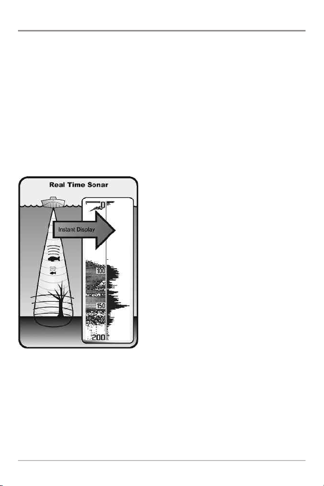
SONAR is an acronym for SOund and
NAvigation Ranging. Sonar utilizes precision
sound pulses or “pings“ which are emitted
into the water in a teardrop-shaped beam.
The sound pulses “echo“ back from objects
in the water such as the bottom, fish, and
other submerged objects. The returned
echoes are displayed on the LCD screen.
Each time a new echo is received, the old
echoes are moved across the LCD, creating a
scrolling effect.
1
How Sonar Works
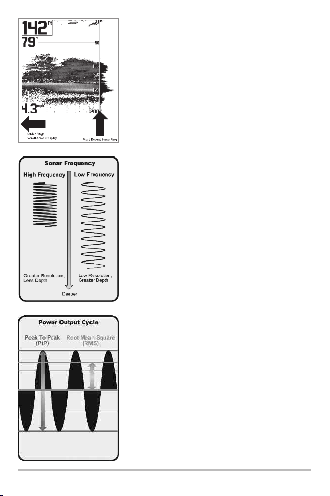
When all the echoes are viewed side by side, an
easy to interpret “graph“ of the bottom, fish, and
structure appears.
The sound pulses are transmitted at various
frequencies depending on the application. Very
high frequencies (455 kHz) are used for greatest
definition but the operating depth is limited. High
frequencies (200 kHz) are commonly used on
consumer sonar and provide a good balance
between depth performance and resolution. Low
frequencies (83 kHz) are typically used to achieve
greater depth capability.
The power output is the amount of energy
generated by the sonar transmitter. It is commonly
measured using two methods:
How Sonar Works
• Root Mean Square (RMS) measures power
output over the entire transmit cycle.
• Peak to Peak measures power output at the
highest points.
The benefits of increased power output are the
ability to detect smaller targets at greater
distances, ability to overcome noise, better high
e, a
speed performanc
nd enhanced depth capability.
2
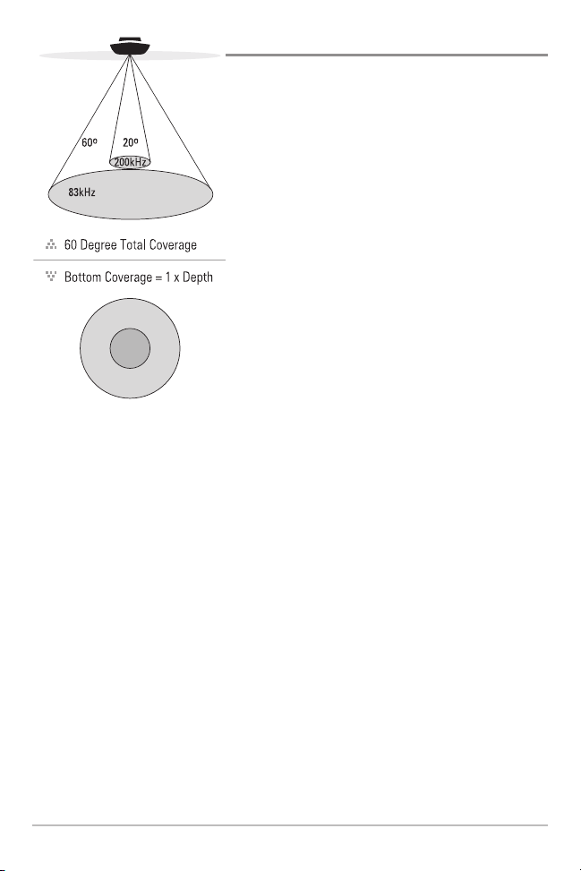
DualBeam Sonar
Your 500 Series™ Fishfinder uses a
200/83 kHz DualBeam sonar system with a wide
(60°) area of coverage. DualBeam sonar is
optimized to show the greatest bottom definition
using a narrow (20°) beam yet can still indicate
fish found in the wide (60°) beam when the Fish
ID+™ feature is turned on. DualBeam is ideal for
a wide range of conditions - from shallow to
very deep water in both fresh and salt water.
Depth capability is affected by such factors as
boat speed, wave action, bottom hardness,
water conditions, and transducer installation.
3
How Sonar Works
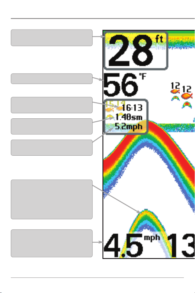
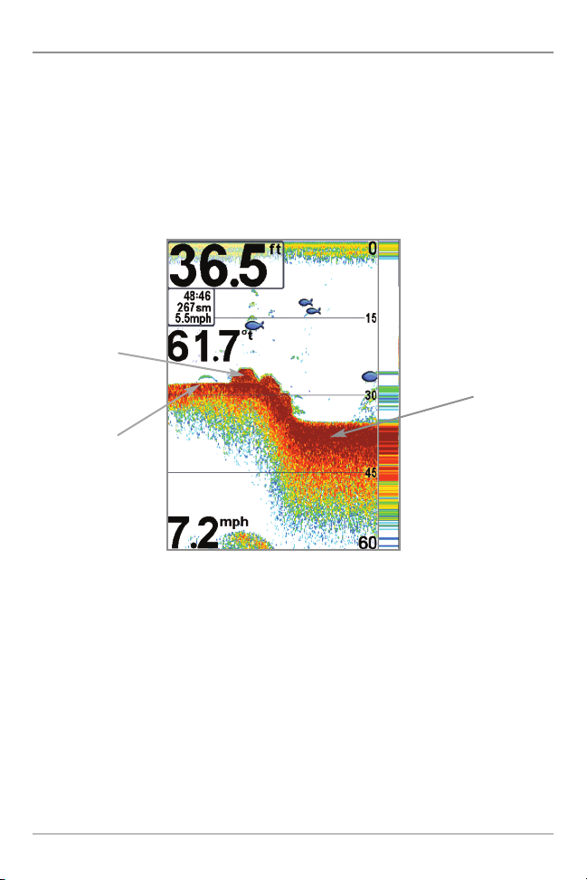
What’s On the Sonar Display
The 500 Series™ Fishfinder can display a variety of useful information about the
Depth - water depth; can be set to alarm when
the water becomes too shallow.
Temperature - water surface temperature.
Timer - Elapsed time with Temp/Speed
Accessory.
Distance - Distance traveled with Temp/Speed
Accessory.
Average Speed - Average speed reading with
Temp/Speed Accessory.
Second Sonar Return - when the sonar signal
bounces between the bottomand thesurface ofthe
water and back again. Use the appearance of the
second return to determine bottom hardness. Hard
bottoms will show a strong second return,while soft
bottoms willshow a very weak oneor none at all.
Speed - if a Temp/Speed accessory is attached,
the Fishfinder can display the speed of the boat
and can keep a Triplog of nautical or statute
miles traveled.
NOTE: Entries in this view that list (with Temp/Speed) are available if the accessory is connected
What’s On the Sonar Display
4
area under and adjacent to your boat, including the following items:
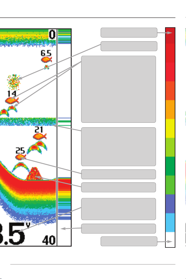
High Sonar Intensity Return
Bait Ball
Fish - the Fishfinder displays fish as arches
and/or fish icons, and can be set to alarm
when a fish of a certain size is detected.
When a target is detected, a Fish ID+™
symbol appears on the display with the
depth displayed above it. The size of the
symbol indicates the intensity of the sonar
return. The unit will clearly show schools of
Bait Fish as "clouds" of different shapes and
sizes, depending on the number of fish and
boat speed.
Thermoclines - layers of water with different
temperatures that appear at different depths
and different times of the year. A thermocline
typically appears as a continuous band of
many colors moving across the display at the
same depth.
200 kHz, Orange Fish Symbol
Structure - where fish may be hiding.
to the 500 Series™ Fishfinder.
Battery Voltage - the voltage of the boat’s
battery; can be set to alarm if the voltage falls
below a certain point.
RTS (Real Time Sonar) Window™
Low Sonar Intensity Return
5
What’s On the Sonar Display
The returned sonar echoes are displayed
on the screen. As a new echo is received,
the historical data scrolls across the screen.
UUnnddeerrssttaannddiinngg tthhee SSoonnaarr DDiissppllaayy
It is important to understand the significance of
the display. The display does not show a literal 3dimensional representation of what is under the
water. Each vertical band of data received by the
control head and plotted on the display represents
something that was detected by a sonar return at
a particular time. As both the boat and the targets
(fish) may be moving, the returns are only showing
a particular segment of time when objects were
detected, not exactly where those objects are in
relation to other objects shown on the display.
What’s On the Sonar Display
6
RReeaall TTiimmee SSoonnaarr ((RRTTSS™)) WWiinnddooww
A Real Time Sonar (RTS™) Window appears on the right side of the display in
the Sonar View only. The RTS Window™ updates at the fastest rate possible for
depth conditions and shows only the returns from the bottom, structure, and
fish that are within the transducer beam. The RTS Window™ plots the depth
and intensity of a sonar return (see Sonar Menu Tab: RTS Window™).
The Narrow RTS Window™
indicates the sonar intensity
through the use of colors. Red
indicates a strong return and
blue indicates a weak return.
The depth of the sonar return
is indicated by the vertical
placement of the return on the
display depth scale.
The Wide RTS Window™
indicates the sonar intensity
through the use of a bar
graph. The length of the
plotted return indicates
whether the return is weak or
strong. The depth of the sonar
return is indicated by the
vertical placement of the
return on the display depth
scale. The Wide RTS
Window™ does not use
grayscale.
IInnssttaanntt IImmaaggee UUppddaattee
Instant Image Update - You can change a variety of sonar menu settings (such
as Sensitivity or Upper Range), and the adjustments will be shown instantly on
the screen.
7
What’s On the Sonar Display
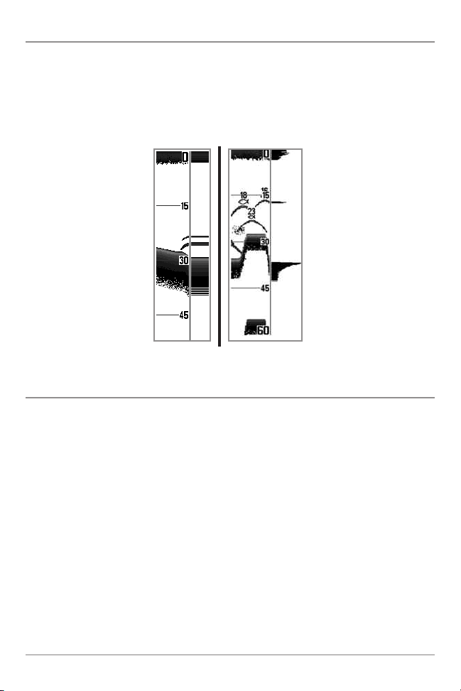
BBoottttoomm PPrreesseennttaattiioonn
As the boat moves, the unit charts the changes in depth on the display to create
a profile of the Bottom Contour. The type of bottom can be determined from
the return charted on the display. A Hard Bottom such as compacted sediment
or flat rock appears as a thinner line across the display. A Soft Bottom such as
mud or sand appears as a thicker line across the display. Rocky Bottoms have
a broken, random appearance.
Bottom Contour Profile with RTS Window™
Rocky Bottom
Soft Bottom
Hard Bottom
The sonar returns from the bottom, structure, and fish can be represented as
either WhiteLine™ or Structure ID®. See Sonar Menu: Bottom View for details
on how to set the bottom view.
What’s On the Sonar Display
8
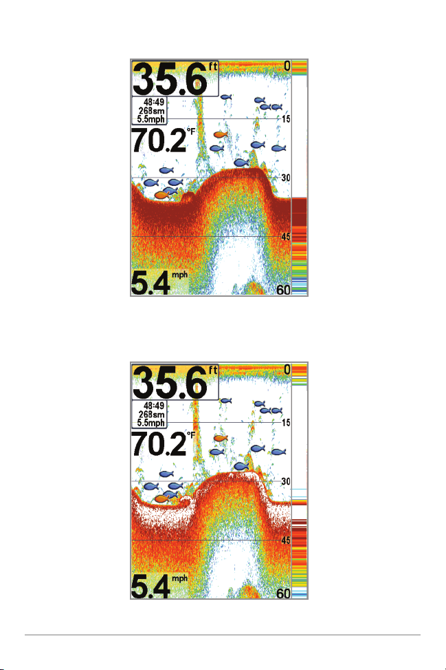
Structure ID® represents weak returns in blue and strong returns in red.
WhiteLine™ highlights the strongest sonar returns in white, resulting in a
distinctive outline. This has the benefit of clearly defining the bottom on the display.
9
What’s On the Sonar Display

Views
Sonar
View
Accessory
Test View
Self Test
View
S
on
a
r
Zo
om
V
ie
w
Big Digits
View
The sonar information from your
Humminbird® Fishfinder is displayed on
your screen in a variety of easy-to-read
views. There are many views available on
your Fishfinder. When you press the VIEW
key, the display cycles through the available
views on your screen. When you press the
EXIT key, the display cycles through the
available views in reverse order.
When you first power up the control head, Sonar View will be the default view.
You can display and hide any view to suit your fishing preferences.
NOTE: When you change any menu settings that affect the sonar, the view will update
immediately. You don't have to exit the menu to apply the change to the screen.
To customize your views rotation:
You can choose which views are hidden or visible in your view rotation.
1. Press the MENU key twice to access the tabbed Main Menu, then
press the RIGHT Cursor key until the Setup tab is selected.
2. Press the DOWN Cursor key to highlight Select Views, and press the
RIGHT Cursor key to access the Select Views submenu.
3. Press the UP or DOWN Cursor keys to select a View.
4. Press the LEFT or RIGHT Cursor keys to change the status of the view
from Hidden to Visible or vice versa.
NOTE: If the Select Views option does not appear under the Setup tab, change the
User Mode to Advanced.
Views
10

To change the Digital Readouts:
Each view displays digital readout information (such as speed or time), which
varies with the view selected and the accessory attached. The digital readouts
in the Sonar View can be customized. See Setup Menu Tab: Select Readouts
for more information.
1. Press the MENU key twice to access the tabbed Main Menu, then
press the RIGHT Cursor key until the Setup tab is selected.
2. Press the DOWN Cursor key to highlight Select Readouts, and press the
RIGHT Cursor key to access the Select Readouts submenu.
NOTE: If the Select Readouts option does not appear under the Setup tab, change the
User Mode to Advanced.
3. Press the UP or DOWN Cursor keys to select a Readout position, then
press the RIGHT or LEFT Cursor keys to choose what will be displayed in
that position. To hide the data window, select Off.
The available views are shown here and described on the following pages.
Sonar views:
Sonar View
Sonar Zoom View
Big Digits View
Self Test View
(see Start-Up Options Menu)
Accessory Test View
(see Start-Up Options Menu)
11
Views
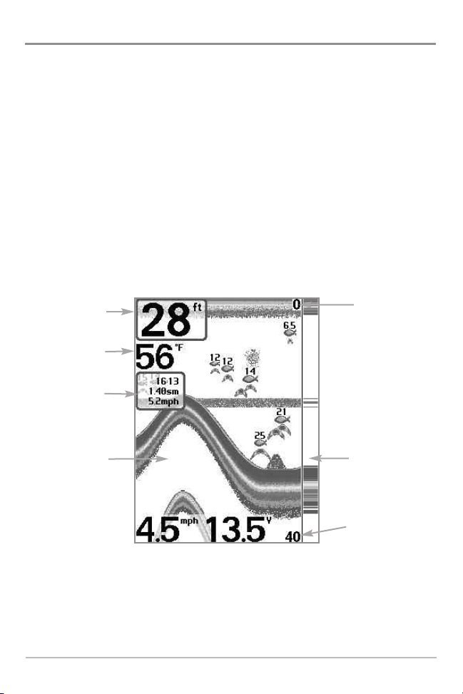
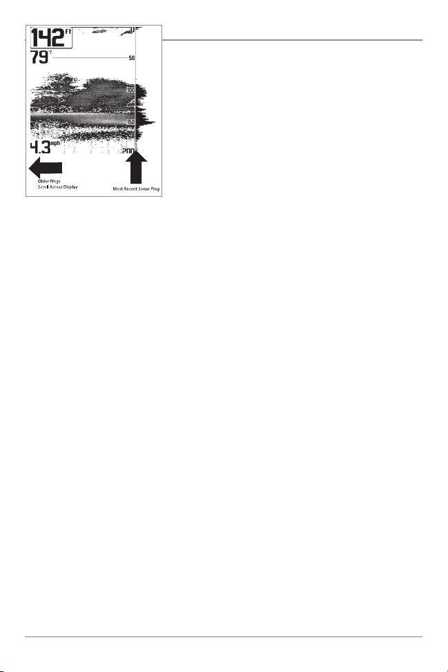
Sonar View
Sonar View presents a historical log of sonar returns. The most recent sonar
returns are charted on the right side of the window. As new information is
received, the historical information scrolls left across the display.
• Upper and Lower Depth Range numbers indicate the distance from the
surface of the water to a depth range sufficient to show the bottom.
• Depth is automatically selected to keep the bottom visible on the display,
although you can adjust it manually as well (see Sonar X-Press™ Menu).
• Digital Readouts shown on the display will change based on the Select
Readouts settings or the optional-purchase accessories attached (see
Setup Menu Tab: Select Readouts).
Sonar View
Depth
Temperature
Triplog
Upper Depth
Range
Sonar History
Window
NOTE: If the Depth number is flashing, it means that the unit is having trouble locating
the bottom. This usually happens if the water is too deep, the transducer is out of the
water, the boat is moving too fast, or for any other reason that the unit can’t accurately
receive continuous data.
Views
12
RTS Window™
Lower Depth
Range

Sonar Zoom View
Sonar Zoom View provides a magnified view of the bottom and structure. The
Sonar Zoom View makes it easier to see separate sonar returns that would
usually be displayed close together, such as those caused by fish suspended
close to the bottom or within structure.
• The Zoom Level, or magnification, is displayed in the lower left corner of
the display. Press the MENU key once to access the Sonar X-Press™
Menu. Highlight Zoom Level, and press the LEFT or RIGHT Cursor keys
to adjust the Zoom Level.
• The Zoomed View is displayed on the left side of the screen. As the
depth changes, the zoomed view updates automatically.
• The Full Range View is displayed on the right side of the screen. The Full
Range View includes the Zoom Preview Box, which shows where the
zoomed view is in relation to the full range view.
• The Upper and Lower Depth Range numbers indicate the high and low
range of the water which is being viewed.
13
Views
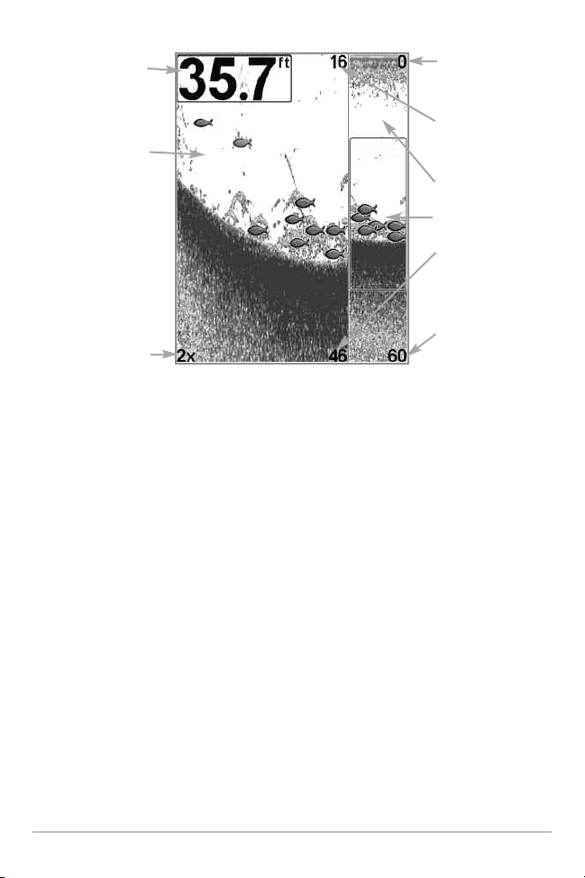
Depth
Zoomed View
Zoom Level
Sonar Zoom View
Digital depth is displayed in the upper left hand corner.
The digital readouts in the Sonar Zoom View cannot be
customized; therefore, information such as water
temperature and voltage are unavailable in the Sonar
Zoom View.
Upper Depth Range,
Full Range View
Upper Depth Range,
Zoom View
Full Range View
Zoom Preview Box
Lower Depth Range,
Zoom View
Lower Depth Range,
Full Range View
Views
14
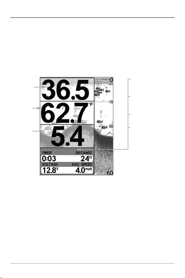
Big Digits View
Big Digits View provides digital data in a large, easy-to-see format. Depth is
always displayed. Readouts for temperature, speed, and Triplog information are
displayed automatically if the appropriate accessory is connected to the
system. The Triplog shows distance traveled, average speed, and time elapsed
since the Triplog was last reset. The digital readouts in the Big Digits View
cannot be customized.
Big Digits View
Timer shows the
Depth
Temperature
Speed
time elapsed since Triplog
was last reset
Distance is the distance
traveled since the Triplog
was last reset
Voltage displays
the battery voltage
Average Speed shows the
speed since the Triplog
was last reset
15
Views
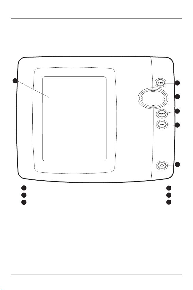
Using Your 500 Series™ Control Head
Your 500 Series™ Fishfinder interface is easy to use. A combination of keys and
special features allows you to control what you see on the display. Refer to the
following illustration, and see Key Functions for more information.
1
Screen
1
VIEW key
2
4-WAY Cursor Control key
3
(LEFT, RIGHT, UP, or DOWN Cursor keys)
MENU key
EXIT key
POWER/LIGHT key
2
3
4
5
6
4
5
6
Using Your 500 Series™ Control Head
16
Key Functions
Your 500 Series™ Fishfinder user interface consists of a set of easy-to-use keys
that work with various on-screen views and menus to give you flexibility and
control over your fishing experience.
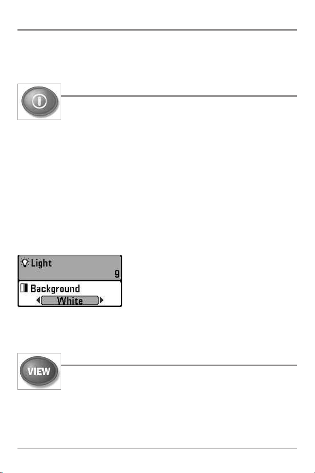
POWER/LIGHT Key
The POWER/LIGHT key is used to power the Fishfinder on and off.
You can also use the POWER/LIGHT key to adjust the backlight
and contrast of the display.
Power On the control head: Press the POWER/LIGHT key to power the unit on.
When the Title screen is displayed, press the MENU key to access the Start-Up
Options Menu.
Power Off the control head: Press and hold the POWER/LIGHT key for 3
seconds. A message will appear to indicate how many seconds there are until
shutdown occurs. To ensure that shutdown occurs properly and any menu
settings will be saved, your Fishfinder should always be turned off using the
POWER/LIGHT key.
Adjust the Backlight or the Display Background
Color: Press the POWER/LIGHT key to access the
Light and Background submenu. Use the 4-WAY
Cursor Control key to select Light or Background,
and then use the LEFT or RIGHT Cursor key to
change the settings. Press EXIT to exit the Light
and Background submenu.
VIEW Key
The VIEW key is used to cycle through all available views. Press the
VIEW key to advance to the next view. Repeatedly pressing VIEW
cycles through all views available. Views can be hidden to optimize the system to
your fishing requirements (see Views or Setup Menu Tab: Select Views).
NOTE: Press the EXIT key to cycle through the views in reverse order.
17
Key Functions
 Loading...