

Humminbird 360 Imaging Installation Manual

360 Imaging
360 Imaging
Installation Guide
Installation Guide
™
™
532050-1_A

Thank You!
Thank you for choosing Humminbird®, the #1 name in Fishfinders. Humminbird® has
built its reputation by designing and manufacturing top-quality, thoroughly reliable
marine equipment. Your Humminbird® accessory is designed for trouble-free use in
even the harshest marine environment. In the unlikely event that your Humminbird®
accessory does require repairs, we offer an exclusive Service Policy - free of charge
during the first year after purchase, and available at a reasonable rate after the
one-year period. For complete details, see the separate warranty card included with
your accessory. We encourage you to read this manual carefully in order to get full
benefit from all the features and applications of your Humminbird® product.
Contact our Customer Resource Center at 1-800-633-1468 or visit our Web site at
humminbird.com.
WARNING! This device should not be used as a navigational aid to prevent collision,
grounding, boat damage, or personal injury. When the boat is moving, water depth may
change too quicklyto allow timefor you to react.Alwaysoperate theboat at veryslowspeeds
if you suspect shallow water or submerged objects.
WARNING! The electronic chart in your Humminbird® unit is an aid to navigation designed
to facilitate the use of authorized government charts, not to replace them. Only official
government charts and notices to mariners contain all of the current information needed for
the safety of navigation, and the captain is responsible for their prudent use.
WARNING! Humminbird® is not responsible for the loss of data files (waypoints, routes,
tracks, groups, recordings, etc.) thatmay occur due to direct or indirect damage to the unit’s
hardwareor software. It is important tobackup your control head’sdatafilesperiodically.Data
files should also be saved to your PC before restoring the unit’s defaults or updating the
software. See your Humminbird® online account at humminbird.com and the Waypoint
Management Guide on your Humminbird® Manual CD for details.
WARNING! Disassembly and repair of this electronic unit should only be performed by
authorized service personnel. Any modification of the serial number or attempt to repair
the original equipment or accessories by unauthorized individuals will void the warranty.
WARNING! This product contains chemicals known to the State of California to cause
cancer and/or reproductive harm.

ATTENTION INTERNATIONALCUSTOMERS: Productssold in the U.S. arenot intended for
use in the international market. Humminbird® international units provide international
features and aredesignedto meet country andregional regulations. Languages, maps,time
zones, units of measurement, and warranty are examples of features that are customized
for Humminbird® international units purchased through our authorized international
distributors.
To obtain a list of authorized international distributors, please visit our Web site at
humminbird.com or contact our CustomerResource Center at (334) 687-6613.
NOTE: Some featuresdiscussed in thismanual requirea separatepurchase,and some features
areonly availableon international models. Every efforthas been madeto clearly identify those
features. Please read the manual carefully in order to understand the full capabilities of your
model.
NOTE: The illustrations in this manual may not look the same as your control head, but your
product will function in the same way.
NOTE: To purchase accessories for your control head, visitour Website at humminbird.com
or contact our Customer Resource Center at 1-800-633-1468.
NOTE: The procedures and features described in this manual are subject to change without
notice. This manual waswritten in Englishand may havebeentranslated to another language.
Humminbird® is not responsible for incorrecttranslations or discrepanciesbetween documents.
NOTE: The installation of this advanced accessory shouldbe performed by a qualified marine
technician.
360 Imaging™, 700 Series™, 800 Series™, 900 Series™, 1100 Series™, Humminbird®, WeatherSense®, and
X-Press™ Menu are trademarked by or registered trademarks of Johnson OutdoorsMarine Electronics, Inc.
© 2012 Johnson Outdoors Marine Electronics, Inc. All rights reserved.

Table of Contents
Introduction 1
Installation Overview 2
Install the GPS Receiver/Heading Sensor 6
1. Choose the Mounting Location . . . . . . . . . . . . . . . . . . . . . . . . . . . . . . . . . . . . . . . . 6
2. Install the Sensor . . . . . . . . . . . . . . . . . . . . . . . . . . . . . . . . . . . . . . . . . . . . . . . . . . . 7
A. Stem Mount with 1” - 14 Thread. . . . . . . . . . . . . . . . . . . . . . . . . . . . . . . . . . . . . 8
B. Access Under the Mounting Location . . . . . . . . . . . . . . . . . . . . . . . . . . . . . . . . 10
C. No Access Under the Mounting Location . . . . . . . . . . . . . . . . . . . . . . . . . . . . . 12
3. Connect to the Control Head . . . . . . . . . . . . . . . . . . . . . . . . . . . . . . . . . . . . . . . . . 14
Install the Transducer Deployment System 16
1. Installation Overview . . . . . . . . . . . . . . . . . . . . . . . . . . . . . . . . . . . . . . . . . . . . . . . 16
2. Choose the Mounting Location. . . . . . . . . . . . . . . . . . . . . . . . . . . . . . . . . . . . . . . . 17
3. Install the Transom Bracket. . . . . . . . . . . . . . . . . . . . . . . . . . . . . . . . . . . . . . . . . . . 20
4. Install the Transducer Bracket. . . . . . . . . . . . . . . . . . . . . . . . . . . . . . . . . . . . . . . . . 22
5. Install the Transducer Deployment System . . . . . . . . . . . . . . . . . . . . . . . . . . . . . . 24
6. Route the Cables and Connect Power . . . . . . . . . . . . . . . . . . . . . . . . . . . . . . . . . . 27
7. Test the Installation . . . . . . . . . . . . . . . . . . . . . . . . . . . . . . . . . . . . . . . . . . . . . . . . . 31
Set up the Control Head 32
1. Power on and Confirm Connections. . . . . . . . . . . . . . . . . . . . . . . . . . . . . . . . . . . . 32
2. Set up 360 Imaging™ on the Control Head . . . . . . . . . . . . . . . . . . . . . . . . . . . . . . 34
3. Test 360 Imaging™ on the Control Head . . . . . . . . . . . . . . . . . . . . . . . . . . . . . . . 36
4. Confirm the Heading Sensor Operation . . . . . . . . . . . . . . . . . . . . . . . . . . . . . . . . 38
5. Confirm the Baud Rate
6. Set up the Network and Alarms . . . . . . . . . . . . . . . . . . . . . . . . . . . . . . . . . . . . . . 40
(for devices connected to the Sensor pigtail only) . . . . . . . . . . 40
Power Off 41
i

Table of Contents
Maintenance 42
Control Head Maintenance . . . . . . . . . . . . . . . . . . . . . . . . . . . . . . . . . . . . . . . . . . . . 42
Transducer Maintenance . . . . . . . . . . . . . . . . . . . . . . . . . . . . . . . . . . . . . . . . . . . . . . 43
Transducer Deployment System Maintenance . . . . . . . . . . . . . . . . . . . . . . . . . . . . . 43
Troubleshooting 44
Fishing System Doesn’t Power Up . . . . . . . . . . . . . . . . . . . . . . . . . . . . . . . . . . . . . . . 44
Fishing System Defaults to Simulator with a Transducer Attached . . . . . . . . . . . . . 45
The Pod Doesn’t Deploy or Retract . . . . . . . . . . . . . . . . . . . . . . . . . . . . . . . . . . . . . . 46
Finding the Cause of Noise . . . . . . . . . . . . . . . . . . . . . . . . . . . . . . . . . . . . . . . . . . . . . 47
Removing the Pod (for authorized repair only) 48
Reconnecting the Pod (for authorized repair only) 51
Specifications 54
Contact Humminbird® 56
ii


Introduction
This manual will guide you through the following installation requirements for the
360 Imaging™ Transducer Deployment System:
Installing the GPS Receiver/Heading Sensor
Installing the Transducer Deployment System
Connecting to the Control Head and Power
Testing the Installation
Powering Off
Before proceeding with this installation, the Humminbird® control head
should be installed. See your Humminbird® control head installation guide
for instructions. The 360 Imaging™ Transducer Deployment System can
be connected directly to the control head or to a Humminbird® Ethernet
Switch (optional) fornetworking. See the EthernetSwitchaccessoryguide
to install the Ethernet Switch.
NOTE: The installation of this advanced accessory shouldbe performed by a qualified marine
technician.
1
Introduction
1 | Installation Overview
Before you start the installation, please take a moment to familiarize yourself with the
parts list and supplies list. We also encourageyou to read the instructionsbeforehand
so that you may understand the installation requirements.
A
B
N
C
D
E
F
H
I
J
K
G
O
P
L
Q
M
Installation
2

Parts
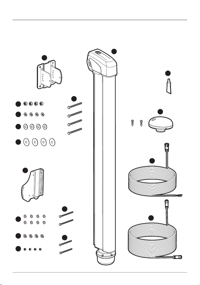
The 360 Imaging™ Transducer Deployment System includes the following items:
A
Transducer Deployment System
B
Transom Bracket
C
(4) 5/16" - 18 Hex Lock Nuts
D
(4) 5/16" Split Ring Lock Washers
E
(4) 5/16" Flat Washers
F
(4) 5/16" Fender Washers
G
(4) 5/16" - 18, 3 1/2" Bolts
H
Transducer Bracket
I
(8) 1/4" - 20 Flat Washers
J
(4) 1/4" Split Ring Lock Washers
K
(4) 1/4" - 20 Hex Lock Nuts
L
(2) 1/4" - 20, 3 3/4" Bolts
M
(2) 1/4" - 20, 3 1/4" Bolts
N
Anti-Seize Tube
O
GPS Receiver/Heading Sensor and screws for mounting
P
Power Cable (6', 2 m)
Q
Ethernet Cable (20', 6 m)
Pod Cover (not shown)
NOTE: Product supplies and features are subject to change without notice.
3
Installation

Supplies
In addition to the hardware included with your Transducer Deployment System, you
will need the following supplies:
Drill with various drill bits
Electrical tape
Awl or pencil
1/2" & 7/16" sizes in wrenches, ratchets, and sockets
Torque wrench with 5 - 7 FT/LB capacity
3M Marine Adhesive Sealant 5200 (recommended)
or Marine Grade Adhesive Sealant
Marine-grade silicone caulk or sealant
Cable ties for cable routing
4' straight edge or level
Tape measure
8 A fuse
Safety goggles
Dust mask
Cables: Depending on your Humminbird® model and system configuration, you
may need to purchase additional cables, as shown below. Visit our Web site at
humminbird.com or call our Customer Resource Center at 1-800-633-1468.
• 700 Series™ with Ethernet: To connect the Ethernet to the control head,
you will need to purchase the Ethernet Adapter Cable (AS EC QDE).
• Extention Cables are available for Ethernet and the GPS Receiver/Heading
Sensor.
• Y-Cable: If the COM port on the control head is already used by another
installed accessory, you will need to purchase a Humminbird® Y-Cable to
add the GPS Receiver/Heading Sensor to the installation.
Installation
4

Switch (optional): If you do not have a main switch or fuse panel available on
your boat to connect power, you will need to purchase a battery switch. See
Install the Transducer Deployment System, Section 6. Route the Cables and
Connect Power for more information.
Lag Bolts (optional): If you are unable or choose not to drill completely through
the transom as recommended, you will need to purchase (4) 5/16" lag bolts of
the appropriate length.
5
Installation

Install the GPS Receiver/Heading Sensor
Use the following instructions to install the GPS Receiver/Heading Sensor (“Sensor”)
on your boat.
1. Choose the Mounting Location
It is important to consider the following information when you choose a mounting
location for the Sensor:
• Interference: Do NOT mount the Sensor close to a VHF antenna or within the
active area of a radar. Do NOT install the Sensor near ferrous metals or near
anything that can create a magnetic field. Hardware and cables that handle
large currents, such as batteries and power cables, are also examples of
equipment that may cause interference.
• Reception: Mount the Sensor in an area that has full exposure to the sky.The
effective area of reception is 5˚ above the horizon.
• Surface: Whether the Sensor Cable will be routed down through the
mounting surface or to the side, or if your’re using a stem mount, the
mounting surface will influence how you install the Sensor. For details, see
Section 2: Install the Sensor.
• Extension Cables: Test run the Sensor Cable from the chosen mounting
location to the control head. 10 ft (3m)extensioncables may be purchased from
Humminbird® if your planned cable route exceeds 20 ft (6 m). Maximum cable
length, including extension cables, should not exceed 50 ft (16 m).
• Y-Cable: If the COM port on the control head is already used by another
installed accessory, you will need to purchase a Humminbird® Y-Cable to add
the Sensor to the installation.
Installation - GPS/Heading Sensor
6
2. Install the Sensor
There are three different options to mount the sensor. Proceed to the section that
matches the type of mounting location you will be using, as follows:
Stem Mount with 1” - 14 Thread
The Sensor will be mounted on a stem or
antenna pole. Proceed to Section A.
Stem
Access Under the Mounting Deck
The Sensor will be deck mounted and the
cable can be routed down through the
mounting surface. Proceed to Section B.
Cable routed through the hole
NO Access Under the Mounting Deck
The Sensor will be deck mounted and the
cable must routed to the side because thereis
not space for a cable through or underneath
the mounting location. Proceed to SectionC.
Cable routed to the side
7
Installation - GPS/Heading Sensor
A. Stem Mount with 1”-14 Thread
Use the following instructions to stem mountthe Sensor:
WARNING! Do NOT mount the Sensor to a stem
mount or antenna pole that contains ferrous metals.
NOTE: It is important to review the mounting
considerations and test run the cable route as
indicated in Section 1 before proceeding with the
installation.
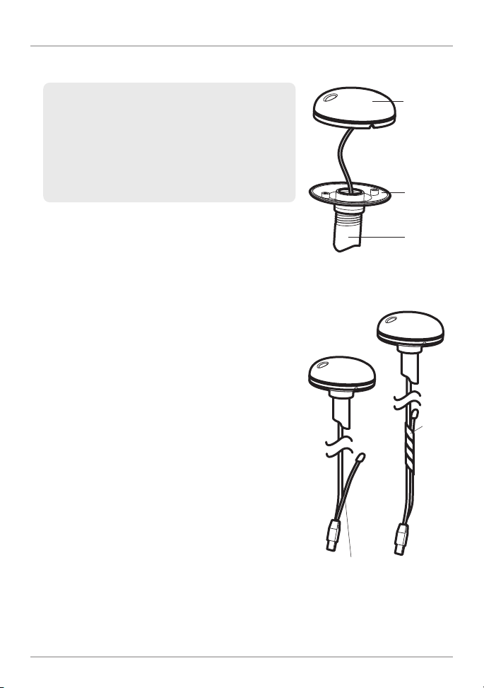
Stem Mount, Attaching the
Sensor Base to the Stem
Cover
Base
1. If you have a pre-existing stem mount, skip to
step 2.
If you need to mount the antenna pole (stem),
mark the chosen mounting location and drill a
3/4” (19 mm) hole for the cable and cable
connector.
If you have purchased hardware to stem
mount your Sensor, follow the instructions
included with that hardware to attach the stem
to the boat.
2. Screw the Sensor base onto the stem first,
making sure that the stem pipe does not
protrude from the Sensor base. (This adds
protection to the cable when it is pulled through
the pipe stem.) Deburr the pipe edges to reduce
cable abrasion.
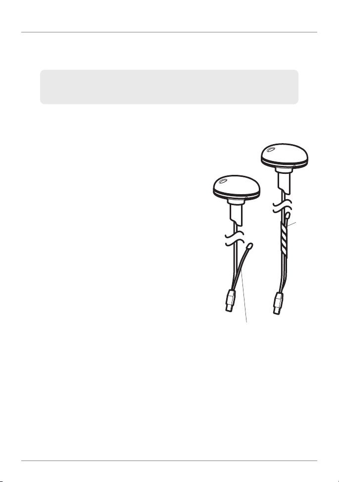
3. Use electrical tape to secure the NMEA pigtail
to the cable.
NOTE: Unless it is needed, leave the NMEA pigtail
secured to the cable. If you are connecting the pigtailto
a NMEA 0183 device, see Section 3: Connect to the
Control Head for connection information.
Stem
Taping the NMEA Pigtail
to the Cable
NMEA Pigtail Cable Out
NMEA
Pigtail
Cable
Taped
Installation - GPS/Heading Sensor
8
4. Route the Sensor cable through the stem and
through the planned cable route. To use
extension cables, see the details in Section 1:
Choose the Mounting Location.
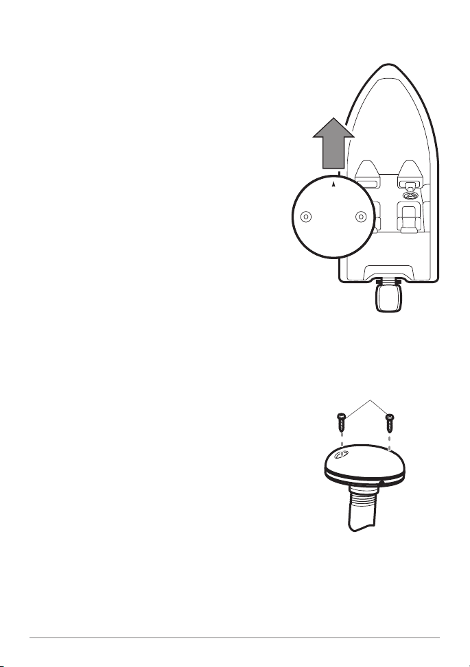
5. Position the Sensor so the arrow on the cover
is pointed straight toward the front of the boat
in the direction of travel. The arrow should be
parallel with the keel.
NOTE: Failure to alignthe Sensor correctly will result in
incorrect compass readings.
6. Attach the Sensor to its base using the
included #6 -1/4” screws. Hand tighten only.
Positioning the Arrow
on the Sensor
Attaching the Sensor
to the Base
#6 -1/4
Mounting Screws
9
Installation - GPS/Heading Sensor
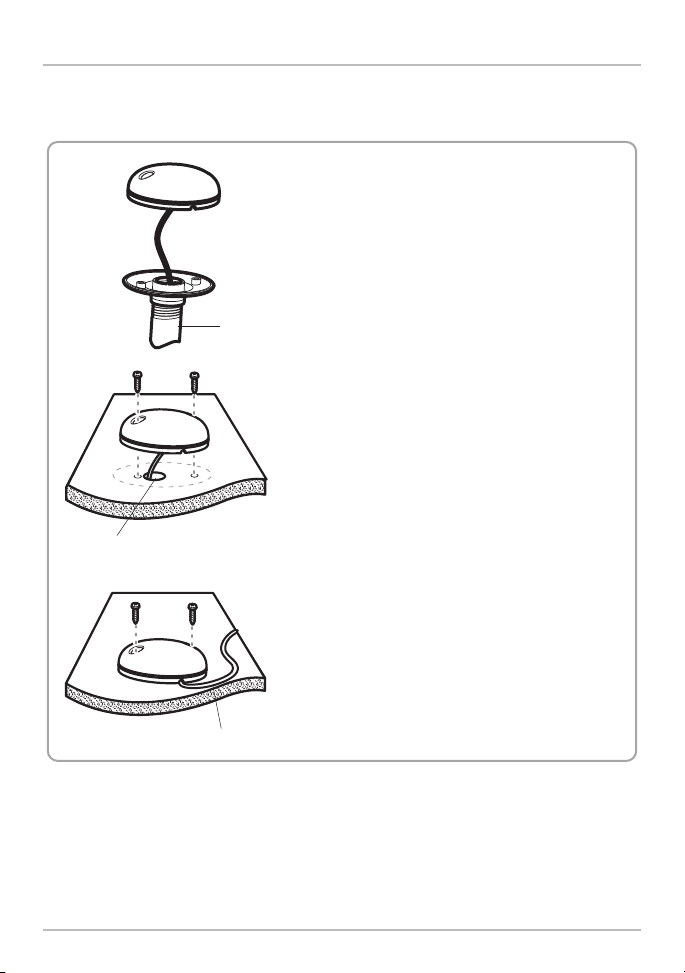
B. Access Under the Mounting Location
Use the following instructions to deck mount the Sensor and route the cable down
through the mounting surface:
NOTE: It is important to review themounting considerations andtest run thecable
route as indicated in Section 1 before proceeding with the installation.
1. Mark the mounting location and drill a 3/4”
(19 mm) hole for the cable and cable connector.
2. Secure the NMEA pigtail to the cable with
electrical tape.
NOTE: Unless it is needed, leave the NMEA pigtail
secured to the cable. If you are connecting the pigtail
to a NMEA 0183 device, see Section 3: Connect to
the Control Head for connection information.
3. Route the Sensor cable through the planned
cable route. To use extension cables, see the
details in Section 1: Choose the Mounting
Location.
4. Cover the cable hole with the Sensor.
Position the Sensor so the arrow on the cover
is pointed straight toward the front of the boat
in the direction of travel. The arrow should be
parallel with the keel.
NOTE: Failure to align the Sensor correctly will result
in incorrect compass readings.
Taping the NMEA Pigtail
to the Cable
NMEA
Pigtail
Cable
Taped
NMEA Pigtail Cable Out
Installation - GPS/Heading Sensor
10
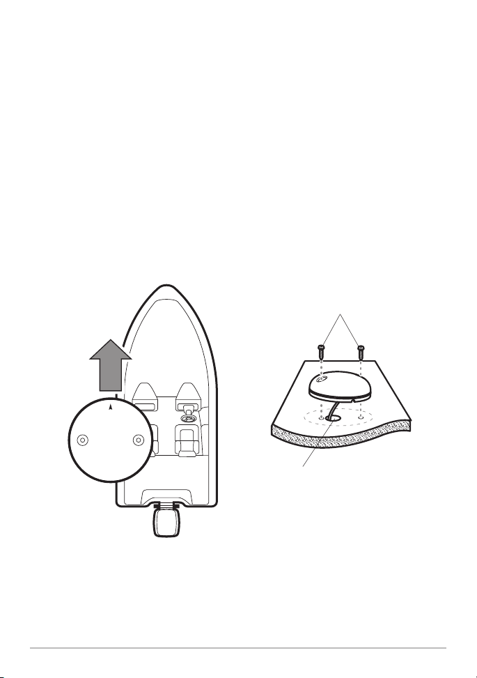
5. Make sure the Sensor is flush against the surface, and mark the two
mounting holes with a pencil or awl.
6. Move the Sensor to the side and drill two pilot holes, using a 5/32”
(4 mm) bit.
NOTE: Apply marine-gradesiliconecaulkor sealant to both screw and drilled holes as
needed to protect your boat from water damage.
7. Alignthe Sensor’s screw holes over the pilot screw holes and attachwith the
#6 - 3/4” Phillips head screws. Hand tighten only.
NOTE: If the mounting surface is thin or made of a light-weight material, you may
need to add reinforcing material below the mounting surface in order to support the
Sensor.
Positioning the Arrow
on the Sensor
11
Attaching the Sensor to the
Mounting Surface
#6 - 3/4
Mounting Screws
Cable routed through the hole
Installation - GPS/Heading Sensor
C. No Access Under the Mounting Location
Use the following instructions to deck mount the Sensor and route the cable to the
side if there is not space for a cable underneath the mounting location:
NOTE: It is importantto reviewthe mountingconsiderationsand test runthe cable
route as indicated in Section 1 before proceeding with the installation.
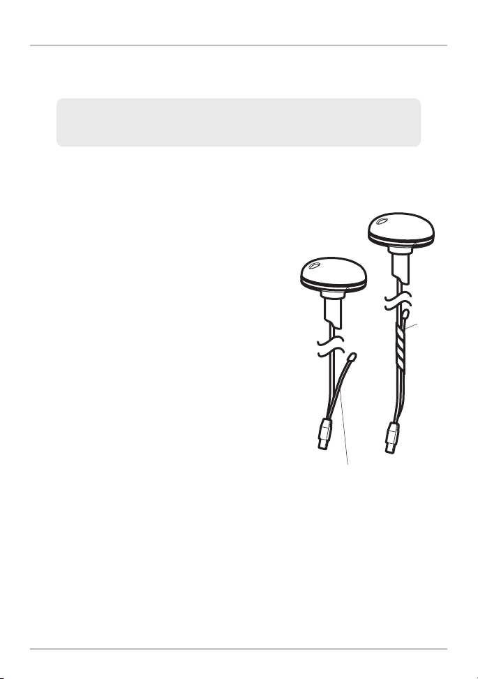
1. Secure the NMEA pigtail with electrical tape.
NOTE: Unless it is needed, leave the NMEA pigtail
secured to the cable. If you are connecting the pigtail
to a NMEA 0183 device, see Section 3: Connect to
the Control Head for connection information.
2. Route the cable from the Sensor to the Control
head.
• The Sensor has two wire routing notches.
Use the cable notch closest to the
intended cable route.
• If holes are required to route the cable,
they must be 3/4” (19 mm) to allow for the
cable connector.
• To use extension cables, see the details in
Section 1: Choose the Mounting Location.
Taping the NMEA Pigtail
to the Cable
NMEA
Pigtail
Cable
Taped
NMEA Pigtail Cable Out
Installation - GPS/Heading Sensor
12
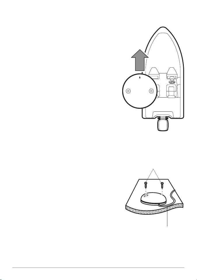
3. With the cable routed, position the Sensor so
the arrow on the cover is pointed straight
toward the front of the boat in the direction of
travel. The arrow should be parallel with the
keel.
NOTE: Failure toalign the Sensor correctly will result in
incorrect compass readings.
4. Make sure the Sensor is flush against the
surface, and mark the two mounting holes
with a pencil or awl.
5. Move the Sensor to the side and drill the two
5/32” (4 mm) pilot holes.
NOTE: Applymarine-grade silicone caulk or sealant to
both screw and drilled holes as needed to protect your
boat from water damage.
6. Align the Sensor’s screw holes over the pilot
screw holes and attach with the #6 - 3/4”
Phillips head screws. Hand tighten only.
Positioning the Arrow
on the Sensor
Attaching the Sensor to the
Mounting Surface
#6 - 3/4
Mounting Screws
13
Cable routed to the side
Installation - GPS/Heading Sensor
 Loading...