

Humminbird 150PT, 190C PT, 160pt User Manual

PiranhaMAX™Portable150PT,160PT,190c PT
PiranhaMAX™Portable150PT,160PT,190cPT
Installation and Operations Manual
Installation and Operations Manual
531679-1_B

Thank You
Thank you for choosing Humminbird®, America's #1 name in fishfinders.
Humminbird® has built its reputation by designing and manufacturing
top-quality, thoroughly reliable marine equipment. Your Humminbird® is
designed for trouble-free use in even the harshest marine environment.In the
unlikely event that your Humminbird® does require repairs, we offer an
exclusive Service Policy-free of charge during the first year after purchase, and
available at a reasonable rate after the one-year period. For complete details,
see the Warranty section of this manual. We encourage you to read this
installation and operations manual carefully in order to get full benefit from all
the features and applications of your Humminbird® product.
Contact our Customer Resource Center at 1-800-633-1468 or visit our website
at www.humminbird.com.
WARNING! This device should not be used as a navigational aid to prevent
collision, grounding, boat damage, or personal injury. When the boat is moving,
water depth may change too quickly to allowtime for you to react. Always operate
the boat at very slow speeds if you suspect shallow water or submerged objects.
CAUTION: Do not handle the bottom of the transducer while it is transmitting
sonar. Prolonged contact with the transducer element can cause physical
discomfort or minor tissue damage.
WARNING! Disassembly and repair of this electronic unit should only be
performed by authorized service personnel. Any modification of the serial number
or attempt to repair the original equipment or accessories by unauthorized
individuals will void the warranty. Handling and/or opening this unit may result
in exposure to lead, in the form of solder.
WARNING! This product contains lead, a chemical known to the state of
California to cause cancer, birth defects and other reproductive harm.
ENVIRONMENTAL COMPLIANCE STATEMENT: It is the intentionof Humminbird®
to be a responsible corporate citizen, operating in compliance with known and
applicableenvironmental regulations, and a good neighbor in the communitieswhere
we make or sell our products.
WEEE DIRECTIVE: EU Directive 2002/96/EC “Waste of Electrical and Electronic
Equipment Directive(WEEE)” impacts most distributors,sellers,and manufacturers of
consumer electronics in the European Union. The WEEE Directive requires the
producer of consumer electronics to take responsibility for the management of waste
from their products to achieve environmentally responsible disposal during the
product life cycle.
i

WEEE compliance may not be required in your location for electrical & electronic
equipment (EEE), nor may it be required for EEE designed and intended as fixed or
temporary installation in transportation vehicles such as automobiles, aircraft, and
boats.In some European Union member states, these vehicles are consideredoutside
of the scope of the Directive, and EEE for those applications can be considered
excluded from the WEEE Directive requirement.
This symbol (WEEE wheelie bin) on product indicates the product must not
be disposed of with other household refuse. It must be disposed of and
collected for recycling and recovery of waste EEE. Humminbird®will mark all
EEE productsin accordance with the WEEE Directive.It is our goal to comply
in the collection, treatment, recovery, and environmentally sound disposal of those
products; however, these requirement do vary within EuropeanUnionmemberstates.
For more information about where you should dispose of your waste equipment for
recycling and recovery and/or your European Union member state requirements,
please contact your dealer or distributor from which your product was purchased.
ROHS STATEMENT: Product designed and intended as a fixed installation or part of
a system in a vessel may be considered beyond the scope of Directive 2002/95/ECof
the European Parliament and of the Council of 27 January 2003 on the restriction of
the use of certain hazardous substances in electrical and electronic equipment.
CALIFORNIA PROPOSITION 65 STATEMENT: Lead in cable jackets and boots is
restricted to 300 parts per million or less as determined by ICP-AES test methods.
NOTE: Some featuresdiscussedin thismanualrequire a separate purchase, and some
features are only available on international or certain models. Every effort has been
made to clearly identify those features. Please read the manual carefully in order to
understand the full capabilities of your model.
NOTE: Illustrations in this manualmay not lookthe same as your product, but your unit
will function in the same way.
Humminbird®, Piranha® , PiranhaMAX™, Fish ID+™, Structure ID®, WhiteLine™, are
trademarked by or registered trademarks of Humminbird® .
© 2008 Humminbird®, Eufaula AL, USA. All rights reserved.
ii

Table of Contents
PiranhaMAX™ Portable Case Assembly 1
1. Assembling the PiranhaMAX™ Mount .................................................. 2
2. Assembling the Base and Handle .......................................................... 2
3. Assembling the Control Head to the Base and Handle.......................... 4
4. Routing the Cables in the Base .............................................................. 5
5. Assembling the Portable Case ................................................................ 8
6. Charging and Installing the Battery........................................................ 9
7. Assembling the Transducer Mounting Bracket ....................................10
8. Stowing the Portable Transducer
and Battery Charger into the Portable Case ..........................................11
Installing the Portable Case on the Boat 12
1. Connecting the Transducer and Power Cables
to the Portable Case ..............................................................................12
2. Attaching the Portable Case to the Boat ..............................................13
Mounting the Portable Transducer 14
1. Testing the Transducer Prior to Installation ..........................................14
2. Mounting the Portable Transducer on the Boat ....................................14
Moving the Portable Fishfinder 16
Powering ON and OFF 17
What You See On the Display 18
PiranhaMAX™ Sonar Technology 19
Single Beam Sonar.................................................................................... 20
Dual Beam Sonar ...................................................................................... 20
iii

Table of Contents
The Menu System 21
Light (Setting Not Saved in Memory) ........................................................ 21
Sensitivity (Setting Saved in Memory) ...................................................... 21
Depth Range (Setting Not Saved in Memory) .......................................... 22
Zoom (Setting Not Saved in Memory)........................................................ 22
Chart Speed (Setting Saved in Memory) .................................................. 23
Fish Alarm (Setting Saved in Memory) ...................................................... 23
Depth Alarm (Setting Not Saved in Memory)............................................ 23
Filter (Setting Saved in Memory) .............................................................. 24
SetUp Menu (Setting Not Saved in Memory)............................................ 24
Contrast (Setting Saved in Memory) .................................................... 24
Fish ID+™ (Setting Saved in Memory) ................................................ 25
Bottom View (Setting Saved in Memory).............................................. 25
Battery Alarm (Setting Saved in Memory)............................................ 27
Language (Setting Saved in Memory, International Only).................... 27
Units (Setting Saved in Memory, International Only) .......................... 27
Maintenance 28
How to Remove Water from the Portable Case........................................ 28
Troubleshooting 29
International Purchases 32
Humminbird® 1-Year Limited Warranty 33
Humminbird® Service Policy 34
Returning Your Unit for Service 35
Specifications 36
Contact Humminbird® 38
NOTE: Entriesin this Tableof Contentswhich list (International Only) are only available
on products sold outside of the U.S. by our authorized International Distributors. It is
important to note that products sold in the U.S. are not intended for resale in the
internationalmarket. Toobtain a listof authorized InternationalDistributors, please visit
our website at www.humminbird.com or contact our Customer Resource Center at
1-800-633-1468 to locate the distributor nearest you.
iv


PiranhaMAX™ Portable Case Assembly
It is important to perform thePiranhaMAX™ portable case assemblytasksin order,
referring to the step-by-step procedures that represent the following main
assembly tasks:
• Assembling the PiranhaMAX™ mount
• Assembling the base and handle
• Assembling the control head to the base and handle
• Routing the cables in the base
• Assembling the portable case
• Charging and installing the battery
• Assembling the transducer mounting bracket
• Stowing the portable transducer and battery chargerinto the portablecase.
When you are done, the control head and the transducer will be part of the
portable case assembly, and you will be ready to take your portable case to the
boat for final setup.
1
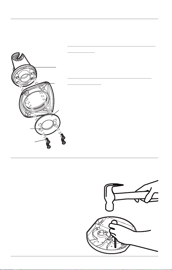
1. Assembling the PiranhaMAX™ Mount
Your PiranhaMAX™mountwill either have a tilt mount or a tilt and swivelmount.
Referto either procedures A or B below to assemble the mount.
Tilt and Swivel
PiranhaMAX™ Mount
A. If you have a tilt mount, refer to the following
information:
No assembly is required for thetilt mount.Proceed
to Assembling the Base and Handle.
Arms
B. If you have a tilt and swivel mount, use the
following steps:
Mount
1. Insert the arms into the mount. Then, hold
the arms in place as you turn the mount
upside down.
Swivel
Ring
2. Insert the swivel ring into the mount, with
the countersink holes for the arm screws
Countersink
Side Out
Arm Screws,
4 #6 x7/16"
facing out.
3. Secure the arms with the 4 #6 screws
provided. Hand tighten only!
2. Assembling the Base and Handle
In this procedure, you will install the PiranhaMAX™ mount and handle to the
base of the portable case.
1. Turn the base upside down.
Punch out the mounting holes
labeled “C” with a hammer and
a screwdriver (or an awl) as
shown in the illustration
Punching Holes.
Punching Holes
2. Turnthe base right side up. Line
up the PiranhaMAX™ mount
withthe holes you punched out
in step 1.
2
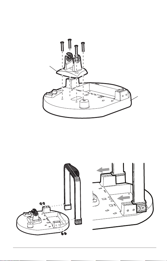
3. Using a socket wrench and a Phillips screwdriver, secure the
PiranhaMAX™ mount to the base with the four included 3/4” screws,
lock washers, and nuts. Hand tighten only!
Attaching the Mount to the Base
PiranhaMAX™ Mount
(tilt OR tilt and swivel)
Base
4. Install the handle onto the base, so that the curved part of the handle
faces towards the back of the base, towards the battery well. Use the
four included #8-32 x 7/16" screws, two on each side, to attach the
handle to the base(seethe illustrations Installing the HandleOnto the
Base and Sliding in the Handle). Hand tighten only!
Installing the Handle Onto the Base
Sliding in the Handle
NOTE: The handle is keyed so that it only fits onto the base in one direction.
3
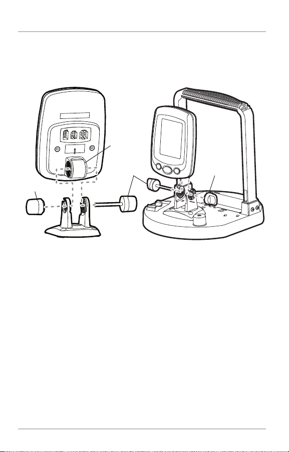
3. Assembling the Control Head to the Base and Handle
In this procedure you will install the control head onto the base assembly.
1. Insertthethumbknob bolt through the pivotknuckle on thecontrol head.
Assembling the Control Head to the Base and Handle
Pivot
Knuckle
Thumbknob
Bolt
Gimbal Knob
Rear View Front View
2. Align the pivotknuckle withthemount arms and slideintoplace, twisting
slightly if necessary, until the unit is firmly seated.
3. Rotate the control head to the desired angle and hand tighten the
thumbknob bolt.
Gimbal Knob
4. Thread the gimbal knob onto the pivot bolt and tighten.
4
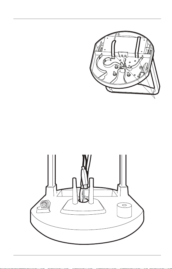
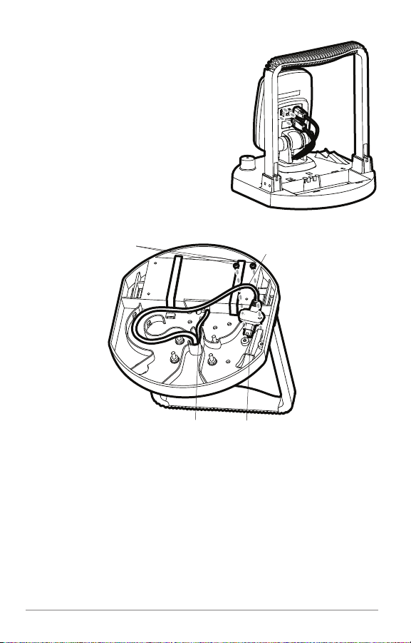
4. Routing the Cables in the Base
In this procedure, you will route the
power and transducerjumper cables on
theunderside of thebase,andattachthe
tie-down straps that will be used to
secure the battery to the base in a later
procedure.
1. Turnthe base upsidedown, then
thread the two included hook
and loop battery tie-down straps
from the bottom of the base up
through each side of the battery
well, using the strap holes (see
the illustration Attaching the
Battery Tie-Down Straps).
2. Routethe powercable from the mountDOWN through the center hole
of the base. Route the transducer jump cable UP through the base
and mount.
Pulling the Cables Through the Base
Attaching the Battery Tie-Down Straps
tie-downstraps
Battery
5
3. Connect the cables to the control head.
The slots for the plugs are keyed to
prevent reverse installation, and
insertion should be easy. Do not to force
the connectors into the control head.
4. Pull the power cable through the
opening in the long side of the cable
well and insert it into the battery well
(see the illustration Installing the
Cables Onto the Base).
Installing the Cables Onto the Base
Screws
Connecting the Cables to the Control Head
Transducer
Jumper
Cable
Power Cable
Jumper Cable Well
5. Route the transducer jumper cable (see the illustration Installing the
Cables Onto the Base) out the long side of the cablewellandfollow the
arrows on the base.
6. Fit the transducer jumper cable connector down into the jumper cable
well and snap it into place. Insert the two #6-32 x 1/4" screws included
to securethe transducer jumper connector and tighten using a Phillips
screwdriver. Hand tighten only!
6
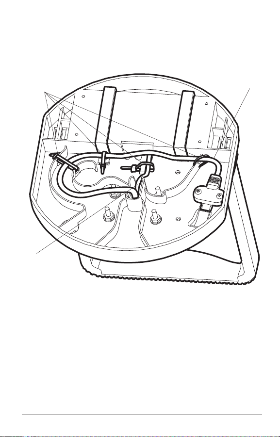
7. Secure all cables to the base, using the included zip ties, at the mount
points shown in the illustration (see the illustration Tying Down the
Cables).
Tying Down the Cables
Zip Tie
Mounting
Point
Power Cable
Transducer
Jumper Cable
8. Turn the base right side up and pull up gently on the battery tie-down
straps to remove the slack.
NOTE: You will need to perform more assembly procedures, as well as charge the
battery for 8 hours, before you install the battery into the portable case. See
Charging and Installing the Battery for more information.
7
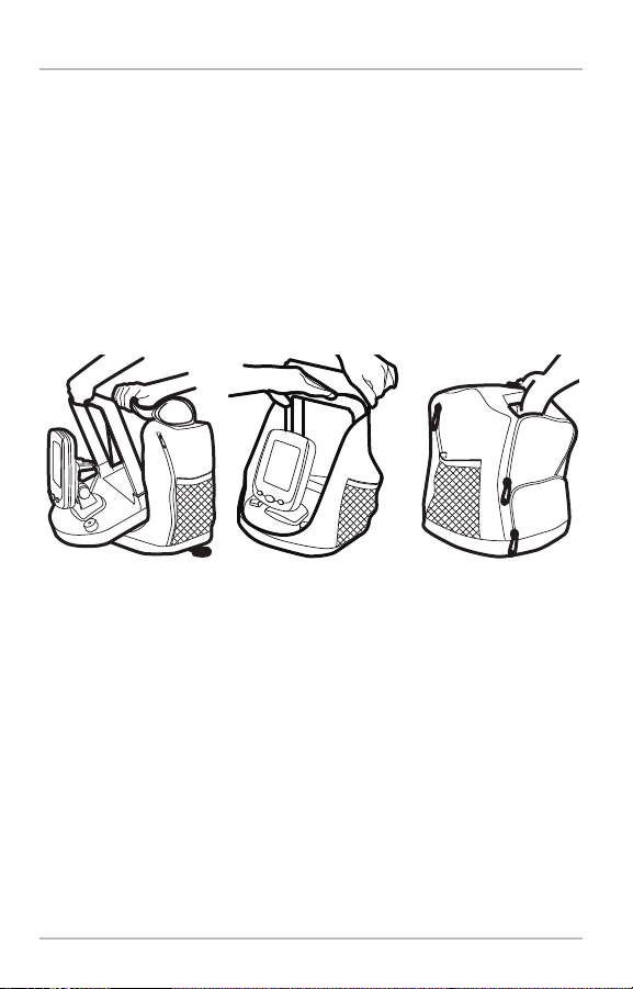
5. Assembling the Portable Case
In this procedure, you will install the base assembly into the portable case.
1. Unzip the largest opening on the front of the portable case.
2. Insert the base assembly into the portable case, so that the
PiranhaMAX™control head is facing out of the case. For best results,
pull the case over one shoulder of the handle at a time.
3. Adjust the case so that you can easily grab the handle, through the
fabric handhold inset, from the outside top of the portable case.
Installingthe BaseintotheCase Pulling theCaseovertheHandle Holding the Portable Case
8
 Loading...