

Huebsch HSGLXFGW091CW01 Parts Diagram
Dryer
DRY576R
Refer to Page 4 for Model Identification
Programming
Keep These Instructions for Future Reference.
(If this machine changes ownership, this manual must accompany machine.)
Part No. 513001R5
November 2011


NOTE: The WARNING and IMPORTANT
Failure to install, maintain, and/or operate
this machine according to the
manufacturer's instructions may result in
conditions which can produce bodily
injury and/or property damage.
W030
WARNING
instructions appearing in this manual are not meant
to cover all possible conditions and situations that
may occur. It must be understood that common
sense, caution, and carefulness are factors which
cannot be built into these dryers. These factors
MUST BE supplied by the person(s) installing,
maintaining, or operating the dryer.
Always contact the distributor, service agent, or the
manufacturer about any problems or conditions you do
not understand.
513001
© Published by permission of the copyright owner – DO NOT COPY or TRANSMIT
1

Table of
Contents
Model Identification ........................................................................... 4
Preliminary Information.................................................................... 5
About the Control ................................................................................. 5
Glossary of Terms................................................................................. 5
Power Failure Recovery ....................................................................... 5
Communications ................................................................................... 5
Control Identification......................................................................... 6
SELECT CYCLE Pads......................................................................... 6
START Pad........................................................................................... 6
Display Identification ......................................................................... 7
Light Emitting Diodes (LEDs) ............................................................. 7
Dryer Operation.................................................................................. 8
Start Up................................................................................................. 8
Ready Mode.......................................................................................... 8
Partial Vend Mode................................................................................ 8
Additional Vend Mode ......................................................................... 8
Start Mode ............................................................................................ 8
Entering Coins ...................................................................................... 8
Entering Cards ...................................................................................... 9
Changing Active Cycles ....................................................................... 9
Opening the Dryer Door ....................................................................... 9
Signals................................................................................................... 9
Extended Tumble Mode ....................................................................... 9
Special Features .................................................................................. 10
Programming Control ........................................................................... 10
Collecting Audit Information ............................................................... 10
Testing Machine and Control Functions............................................... 10
Rapid Advance Feature......................................................................... 10
Clearing the Vend Feature .................................................................... 10
Communications Mode......................................................................... 10
Coin Drop ............................................................................................. 10
Start Pulse Operation ............................................................................ 11
Service Door and Coin Vault Openings ............................................... 11
Special Vend......................................................................................... 11
OPL Mode ............................................................................................ 11
Drop-Off Mode..................................................................................... 11
Low Power/Auto-Shutdown Option ..................................................... 11
Opening the Service Door .................................................................. 12
Stacked Washers and Dryers, Stacked Dryers,
Front Control Dryers, and Coin Rear Control Dryers........................ 12
Rear Control Dryers with Card Reader ................................................ 12
Entering the Manual Mode................................................................ 13
How to Enter the Manual Mode ........................................................... 13
Programming Control ........................................................................ 15
What Can Be Programmed? ................................................................. 15
© Published by permission of the copyright owner.
All rights reserved. No part of the contents of this book may be reproduced or transmitted in any form or by any
means without the expressed written consent of the publisher.
2
© Published by permission of the copyright owner – DO NOT COPY or TRANSMIT
513001

Programmable Options Available......................................................... 15
1. Heat Vend Price “AtSH” ............................................................ 23
2. Coin #1 Value “dEn1” ................................................................ 24
3. Coin #2 Value “dEn2” ................................................................ 25
4. Start Pulse Value “PLSE” ........................................................... 26
5. Start Pulse Mode “PLSn” ............................................................ 27
6. Available Type “AtyP” ............................................................... 28
7. Default Cycle “dCYC” ............................................................... 29
8. OPL Mode Enable/Disable “oPL” .............................................. 30
9. Audio Signal “Aud” or “AUd”* ................................................. 31
10. Card Reader Display Control “CArd” ........................................ 33
11. Error Code Programming “Err-” ................................................. 34
12. Top-Off Data “toP-” ................................................................... 35
13. Cycle Time “CyC-” ..................................................................... 36
14. Cool Down Time “Cdt-” ............................................................. 37
15. Temperature “tEP-” .................................................................... 38
16. Temperature (Fahrenheit/Celsius) “t FC” ................................... 39
17. No Heat Vend Price “AtSn” ....................................................... 40
18. Set Real-Time Clock “rtC-” ........................................................ 41
19. Special Vend A Data “SPA-” ..................................................... 42
20. Special Vend B Days Enable “SPb-” .......................................... 56
21. Special Vend C Days Enable “SPC-” ......................................... 56
22. Special Vend D Days Enable “SPd-” .......................................... 57
23. Drop Off Mode (On/Off) “droP” ................................................ 58
24. Low Power/Auto Shutdown A Days Enable “LPSA” ................ 58
25. Low Power/Auto Shutdown B Days Enable “LPSb” ................. 59
26. Low Power/Auto Shutdown C Days Enable “LPSC” ................. 59
27. Low Power/Auto Shutdown D Days Enable “LPSd” ................. 60
28. Power Fail Reset “PFr” ............................................................... 60
29. IR Access (On/Off) “IrA” ........................................................... 62
30. Manual Rapid Advance (On/Off) “rAEn” .................................. 62
31. Manual Diagnostics (On/Off) “dAEn” ....................................... 63
32. Production Test Cycle (On/Off) “PtEn” ..................................... 63
Collecting Audit Information ............................................................ 64
Manual Reset....................................................................................... 65
Testing Machine and
Electronic Control Functions............................................................. 66
Diagnostic Test Descriptions................................................................ 68
Production Test Cycle........................................................................... 72
Error Codes......................................................................................... 73
Rapid Advance Feature...................................................................... 75
Clear Vend Feature ............................................................................ 76
Power Fail Recovery........................................................................... 77
Power Fail Reset Disabled.................................................................... 77
Power Fail Reset Enabled..................................................................... 77
Communications Mode ...................................................................... 78
Infra-red Communications.................................................................... 78
Card Reader Communications
(Card Models Only)............................................................................ 78
Network Communications.................................................................... 78
513001
© Published by permission of the copyright owner – DO NOT COPY or TRANSMIT
3

Model Identification
Information in this manual is applicable to these dryer
models:
.
BD3LLFGS401UN01
BD3LLFGS401UW01
BD3LLFSS401UN01
BD3LXFGS401UN01
BD3LXFGS401UW01
BD3LXFSS401UN01
BDGLLFGS301EN01
BDGLLFGS301EW01
BDGLLFSS301EN01
BDGLXFGS301EN01
BDGLXFGS301EW01
BDGLXFSS301EN01
BT3LLFSG401UN01
BT3LLFSG401UW01
BT3LLFSP401UN01
BT3LLFSP401UW01
BT3LXFSG401UN01
BT3LXFSG401UW01
BT3LXFSP401UN01
BT3LXFSP401UW01
HDELEFGS151CW01
HDELEFGS151CWNA
HDELEFGS171CQ01
HDELEFGS171CW01
HDELERGS151CW01
HDELERGS151CWNA
HDELERGS171CW01
HDELXFGS151CW01
HDELXFGS171CW01
HDELXFGW171CN01
HDELXFSW171CN01
HDELXRGS151CW01
HDELXRGS171CW01
HDELYFGS151CW01
HDELYFGS171CW01
HDELYRGS151CW01
HDELYRGS151CWNA
HDELYRGS171CW01
HDGLEFGS111CW01
HDGLERGS111CW01
HDGLERGS111CWNA
HDGLXFGS111CW01
HDGLXFGS111CWNA
HDGLXFGW111CN01
HDGLXFSW111CN01
HDGLXRGS111CW01
HDGLYFGS111CW01
HDGLYFGS111CWNA
HDGLYRGS111CW01
HSELXFGW281CW01
HSELXFGW291CW01
HSELYFGW281CW01
HSELYFGW291CW01
HSGLXFGW091CW01
HSGLYFGW091CW01
HTELXFSP281CW01
HTELXFSP291CW01
HTELYFSP281CW01
HTELYFSP291CW01
HTENXFSP281CW01
HTENXFSP291CW01
HTENYFSP281CW01
HTENYFSP291CW01
HTGLXFSP091CW01
HTGNXFSP091CW01
ND3LLFSS401UN01
ND3LXFSS401UN01
NDELXFGS301UW01
NDGLLFSS301EN01
NDGLXFGS301EW01
NDGLXFSS301EN01
NT1LLFSP411CW01
NT1LLFSP411UW06
NT1LXFSP401UN01
NT1LXFSP401UW01
NT2LLFSP401UN01
NT2LLFSP401UW01
NT2LLFSP401UW06
NT2LXFSP401UN01
NT2LXFSP401UW01
NT3LLFSG401UW01
NT3LXFSG401UW01
NT3LLFSP401NN22
NT3LLFSP401NW22
NT3LLFSP401UN01
NT3LLFSP401UW01
NT3LXFSP401UN01
NT3LXFSP401UW01
NTHLXFSP571NW01
NTHLYFSP571NW01
RDELYFGS151CW01
RDELYFGS171CW01
RDGLYFGS111CW01
SDELCFGS171TW01
SDELCFGW171TN01
SDELCFSW171TN01
SDELCRGS151TW01
SDELCRGS171TW01
SDELCRGS171TW02
SDELCRGS171TWNA
SDELXRGS171TW01
SDELXRGS171TW02
SDELXRGS301AW01
SDELYFGS171TW01
SDELYFGW171TN01
SDELYFSW171TN01
SDELYRGS151TW01
SDELYRGS171TW01
SDGLCFGS111TW01
SDGLCFGW111TN01
SDGLCFSW111TN01
SDGLCRGS111TW01
SDGLCRGS111TW02
SDGLCRGS111TWNA
SDGLXRGS111TW01
SDGLYFGS111TW01
SDGLYFGS111TWNA
SDGLYFGW111TN01
SDGLYFSW111TN01
SDGLYRGS111TW01
SDGLYRGS111TWNA
SDGLXRGS111TW02
SDGLXRGS301AW01
SSELCFGS151TW01
SSELCFGS171TW01
SSELCFGW151TW01
SSELCFGW171TN01
SSELCFGW171TW01
SSELXFGW171TW01
SSELYFGS171TW01
SSELYFGW171TN01
SSELYFGW171TW01
SSELYFGW171TWNA
SSGLCFGS111TW01
SSGLCFGS111TWNA
SSGLCFGW111TN01
SSGLCFGW111TW01
SSGLCFGW111TWNA
SSGLXFGW111TW01
SSGLYFGS111TW01
SSGLYFGS111TWNA
SSGLYFGW111TN01
SSGLYFGW111TW01
SSGLYFGW111TWNA
ST3LXFSP401NW22
STELCFSP171TW01
STELXFSP171TW01
STELYFSP171TW01
STENCFSP171TW01
STENXFSP171TW01
STENYFSP171TW01
STGLCFSP111TW01
STGLCFSP111TWNA
STGLXFSG111TW01
STGLXFSP111TW01
STGLYFSP111TW01
STGLYFSP111TWNA
STGNCFSP111TW01
STGNXFSG111TW01
STGNXFSP111TW01
STGNYFSP111TW01
4
© Published by permission of the copyright owner – DO NOT COPY or TRANSMIT
513001

Preliminary Information
About the Control
This control is an advanced, programmable computer
that lets the owner control machine features by
pressing a sequence of SELECT CYCLE pads. Refer
to Figure 1.
The control allows the owner to program custom
cycles, set vend prices, retrieve audit information, run
diagnostic tests, program special vend features and
other programmable features. Refer to Programming
Control for a list of features. Dryers shipped from the
factory have a default cycle (MED TEMP) built in.
However, the owner can change the default cycle, or
any cycle, as needs permit.
IMPORTANT: In the event of a power failure, the
control will not have to be reprogrammed. It is
designed with a memory system that will remember
how it was programmed (for up to 10 years) until
the electrical power is restored.
IMPORTANT: It is extremely important that the
dryer has a positive ground and that all mechanical
and electrical connections to the control are made
before applying power to or operating the dryer.
Glossary of Terms
The following are a few terms and abb reviations to
learn. These are referred to throughout the instructions.
Display – This term refers to the window area of the
control that displays words and values.
LED (Light Emitting Diode) – This term refers to the
lights next to the keypads and status words of
the control.
Power Failure Recovery
If a cycle is in progress and the power fails, the cycle
status is saved in memory. When the power recovers,
the dryer will resume into the previously active cycle
(if so programmed by the owner), by pressing the
START pad. If the power failure occurs while the
control is in a fatal error mode, it will return to Ready
Mode upon recovery.
The owner may program a special feature called
POWER FAIL RESET which sets a maximum power
failure duration. To program this feature, refer to
Programming Control, option 28.
If the length of the power failure is greater than the
POWER FAIL RESET time, the control will end the
cycle and the display will revert back to the Ready
Mode rather than resume the previously active cycle.
If the length of the power failure is less than the
POWER FAIL RESET time and the power failure is
greater than 2 seconds, or the POWER FAIL RESET
is turned off, the dryer will enter START mode.
Communications
The control may be programmed manually, by
infra-red with an external device or by the network. A
limited number of features can be programmed by a
card reader.
Infra-red Communications (Optional)
An external device, such as a PDA, allows the owner
to program and retrieve information from the control
without touching the keypad. An external device
greatly expands the programming options available to
the owner. However, the external device is not required
to program and operate the dryer. The operation of an
external device and the advanced features available are
covered separately in the instructions included with
the external device software. Contact Alliance
Laundry Systems for a list of approved PDAs and
other external devices.
Serial Card Reader Communications
(Card Models Only)
The control will accept communication with a serial
card reader in order to perform vending transactions
when a card is inserted to pay for cycles. The card
reader can also allow the owner to program and collect
audit information.
For detailed information on serial card reader
communications, refer to instructions included with
card reader.
Network Communications
The control will also accept communication with a
network interface board which allows the control to be
linked to a personal computer. This network link
allows an owner to program, collect data and run
diagnostics on any machine.
For detailed information on network communications,
refer to the network instructions.
513001
© Published by permission of the copyright owner – DO NOT COPY or TRANSMIT
5

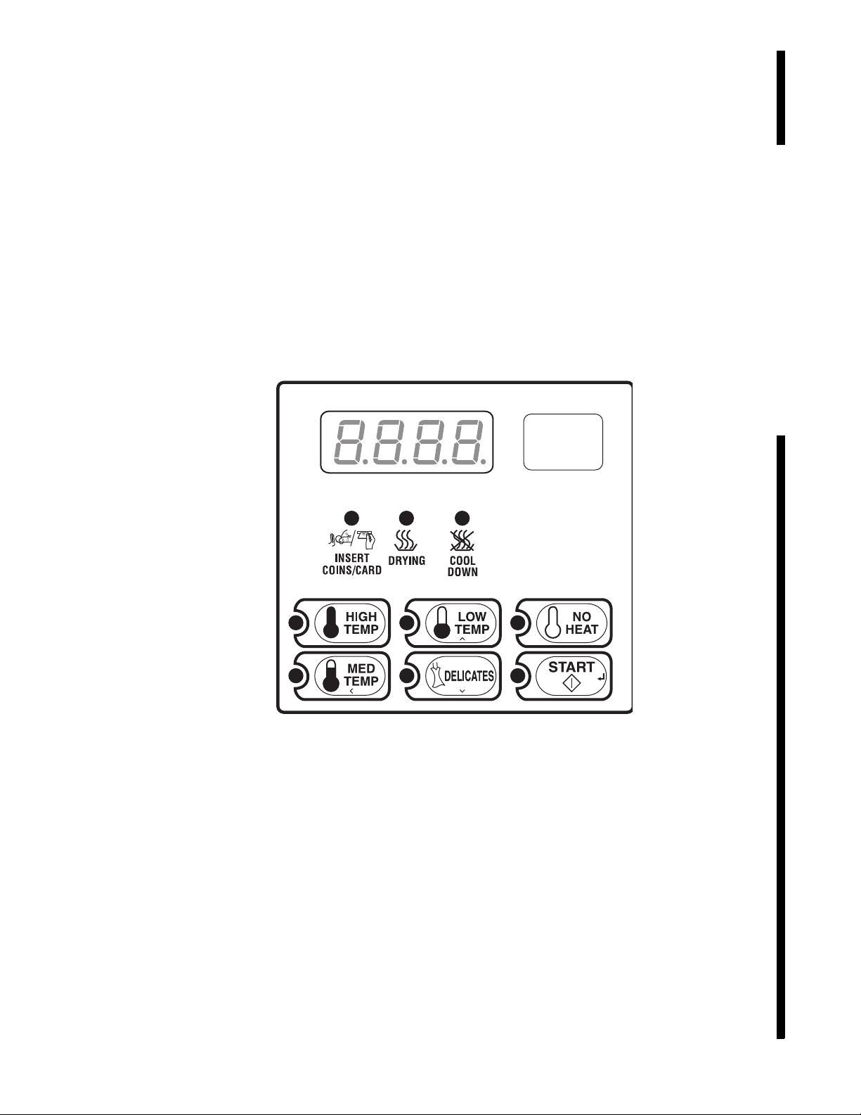
Control Identification
6
1
2
3
Electronic Control
5
4
SELECT CYCLE Pads
(Refer to Figure 1)
SELECT CYCLE pads are used to select the specific
dryer cycle and temperature. These pads include
HIGH TEMP, MED TEMP, LOW TEMP,
DELICATES and NO HEAT. The selection of one of
these cycles will light up the corresponding LED. The
factory default cycle is MED TEMP.
START Pad
(Refer to Figure 1)
The START pad is used to start the dryer after the full
vend price has been satisfied and the dryer door is closed.
Both the START pad and the SELECT CYCLE pads are
used in various combinations for programming cycles,
retrieving audit information, running diagnostic tests,
and other operations. During an active cycle (card reader
equipped machines only), the START pad may be
pressed (with a card inserted) to add time to a cycle.
1 Display
2 7-Segment Digits
3 START Pad
4 SELECT CYCLE Pads
5 LED Light
6 LED Status Lights
6
DRY576R
Figure 1
© Published by permission of the copyright owner – DO NOT COPY or TRANSMIT
DRY576R
513001

Display Identification
Light Emitting Diodes (LEDs)
(Refer to Figure 1)
LIGHT EMITTING DIODES (LEDs) are used to
indicate the chosen temperature and cycle status. See
below for information on each LED.
INSERT COINS/CARD LED
The INSERT COINS/CARD LED is lit to prompt the
user to insert coins or a card to satisfy the vend price
for the chosen cycle. The LED is lit during the
“Ready” mode. During Partial and Additional Vend,
the LED flashes one second on and one second off.
The INSERT COINS/CARD LED will shut off when
the vend price has been satisfied.
START LED
The START pad LED flashes whenever the dryer is
not in a cycle, the full vend price has been satisfied,
and the dryer door is closed. When the START pad is
pressed, the cycle will begin or resume. The START
LED will shut off when the START pad is pressed.
The START LED will also flash any time a card is
inserted to add time to the current cycle.
COOL DOWN LED
The COOL DOWN LED is lit whenever the COOL
DOWN portion of a heated cycle is active. It is also lit
when the NO HEAT cycle is in operation. The COOL
DOWN LED will shut off when a cycle ends or more
time is added, pushing the cycle back into the heated
portion of a cycle.
Four 7-Segment Digits
The 7-SEGMENT DIGITS are used to display the
time remaining in a cycle, vend price, error messages
and descriptive codes. During diagnostic testing or
manual programming of the control, these digits will
display descriptive codes and values (as described in
Entering the Manual Mode).
DRYING LED
The DRYING LED is lit to indicate that one of the
heated cycles (HIGH TEMP, MED TEMP, LOW
TEMP, DELICATES) is currently in operation. The
DRYING LED goes off at the end of a heated cycle, if
the heated cycle is changed to a NO HEAT cycle, or
when the COOL DOWN cycle begins.
513001
© Published by permission of the copyright owner – DO NOT COPY or TRANSMIT
7

Dryer Operation
Start Up
When power is applied to the dryer, the control
becomes active and will display its software version as
“SXX” (“XX” is the version number) for one second
and then the subversion as “XX” (if subversion isn’t
zero) for one second. If the control was not powered
down during a running cycle, it will enter the Ready
Mode.
Ready Mode
In Ready Mode, the default cycle LED is lit, and the
full vend price is displayed.
The user may select a different cycle, if desired. If the
vend price is not satisfied within 4.25 minutes, the
dryer control will return to the Ready Mode. The
display will continue to show the remaining vend
needed to start a cycle.
Partial Vend Mode
The control enters this mode when part of the vend
price has been entered, but not enough vend is entered
to satisfy the vend price. The control will display the
remaining vend price needed to start the cycle and the
INSERT COINS/CARD LED is lit.
Start Mode
Vends may be satisfied by a coin drop, start pulses, or
by a third party card reader. If a coin drop is used, the
remaining vend price will decrease with each coin
entry. If start pulses are used, the remaining vend price
will decrease with each received pulse. Once the vend
is satisfied, the START LED will begin to flash and
signal will sound for ten seconds. If a third party card
reader is used, the START LED will begin to flash
when a valid cash card is entered into the reader.
When the START keypad is pressed, the dryer will
start. The START LED will stop flashing and either
the DRYING LED or the COOL DOWN LED will be
lit. The display will change to show the remaining
cycle time on the display. The DRYING LED will be
lit during the heat portion of a heat cycle. The COOL
DOWN LED will be lit during the cool down portion
of a heat cycle and during an entire no heat cycle.
When a cycle is complete, the display will show “00”
until the door is opened, a key is pressed, a coin or
card is entered, or a start pulse is received. When any
of the above happens, the display will revert back to
the Ready Mode.
Entering Coins
Additional Vend Mode
The control enters this mode if the cycle is changed to
a cycle that requires more money. If the vend price is
not satisfied within 60 seconds, the control will go
back to the first selection and the cycle will continue.
Coins are entered to satisfy the programmed vend
price for a selected cycle. Coins may be entered before
selecting a cycle or during an active cycle. When coins
are entered during an active cycle, the time remaining
is increased by the amount programmed by the owner
(refer to Programming Control).
The owner may choose to add additional time for each
coin entered. If coins are entered for an active cycle
currently in the COOL DOWN Mode, coins entered
may push the cycle back into the DRYING Mode. The
maximum time for any cycle is 99 minutes.
8
© Published by permission of the copyright owner – DO NOT COPY or TRANSMIT
513001

Dryer Operation
Entering Cards
A card is entered to satisfy the programmed vend price
for a selected cycle. The card may be entered before
selecting a cycle or during an active cycle. When the
card is entered during an active cycle and the START
keypad is pressed, the time remaining is increased by
the amount programmed by the owner. Refer to
Programming Control section.
The owner may choose to add additional time by
deducting a vend from the card or may require an
additional full vend price be deducted from the card. If
vend is deducted during an active heated cycle that is
currently in the COOL DOWN Mode, the additional
time added may put the cycle back into the DRYING
Mode. The maximum time for any cycle is 99 minutes.
Additional time cannot be added if it exceeds the
99 minute limit on a drying cycle.
Changing Active Cycles
In OPL machines, the active cycle may be changed at
any time during dryer operation. In vend machines, the
active cycle may be changed in the first five minutes
for more expensive cycles. Cycles that are the same
price or less expensive can be chosen anytime. The
last five minutes of cycle can be changed with no
change to vend or time remaining.
Signals
There are six instances when a signal may sound
during dryer operation. The owner may program the
signal to be turned on or off (refer to Programming
Control, option 9). These six instances are listed
below:
1. End of Cycle Signal
By default, this signal is turned off. If turned on,
the signal will sound for three seconds at the end
of a cycle.
2. Keypad Depression Signal
The signal will sound for a quarter of a second
each time a keypad is pressed.
3. Coin Input/Start Pulse Input/Card Insertion
Signal
The signal will sound for a quarter of a second
each time a coin or start pulse is received or a
card is entered.
4. Remove Card Signal
This signal will sound one second on and one
second off while the control prompts for card
removal.
5. Start Pad Flashing Signal
Opening the Dryer Door
Opening the dryer door in a running cycle will
automatically stop the cycle. When the dryer door is
opened, the DRYING LED or COOL DOWN LED is
turned off.
NOTE: When the door is opened during an active
cycle, the time will continue to count down and the
display will toggle every five seconds between
showing “door” and the remaining cycle time.
Once the dryer door is closed, the START pad LED
flashes at one second intervals until the START pad is
pushed. Pressing the START pad will start or resume
the active cycle.
This signal will sound one second on and one
second off when the START LED is flashing, for
the first ten seconds after vend has been satisfied.
6. Extended Tumble Mode Signal
This signal cannot be disabled. While in
extended tumble mode, the signal will sound one
second on and one second off for five seconds
and then continuously for five seconds before
starting the extended tumble.
Extended Tumble Mode
The control enters Extended Tumble Mode twenty
minutes after a cycle has ended. The signal will sound
one second on and one second off for five seconds and
then continuously for five seconds before starting the
extended tumble, which lasts two minutes, every hour,
for up to 18 hours. Extended Tumble Mode ends with
any user interaction.
513001
© Published by permission of the copyright owner – DO NOT COPY or TRANSMIT
9

Special Features
Programming Control
The control allows the dryer owner to program the
control with the use of the keypad. Cycle and vend
information may be programmed, audit information
may be viewed and diagnostic tests may be run by
pressing keypad combinations.
For details on programming cycle and vend information,
refer to Programming Control.
Collecting Audit Information
The control will store audit information in its memory
that can be retrieved by pressing various keypad
combinations. The control will record coins entered,
total machine cycles, top-offs, and total start pulses.
For more information on the audit features, refer to
Collecting Audit Information.
NOTE: Additional audit information is retrievable
with an external device, a card reader or a
network. Refer to the appropriate instruction
manual.
Testing Machine and Control
Functions
Special programmable diagnostic features built into
the control allow the owner to run specific diagnostic
tests. By opening and closing the service door, with
coin vault closed, and then pressing various sequences
of keypads, the owner may retrieve and perform the
following tests:
Control Software Version Number
Service Door Opening Test
Coin Vault Opening Test
Rapid Advance Feature
This feature allows the user to quickly advance
through an active dryer cycle or advance into a cycle
from the Ready Mode. This feature is useful when
tests must be performed immediately on a dryer
currently in an active cycle. In this case, the user can
quickly advance through the cycle to the Ready Mode.
At this point, the user can perform the required tests
and then return the dryer to the active cycle.
For detailed information on using the Rapid Advance
feature, refer to Rapid Advance Feature.
Clearing the Vend Feature
This feature allows the user to return the control back
to the Ready Mode if coins have been entered but the
full vend price has not yet been satisfied, while in
Partial Vend Mode.
For more information on using the Clear Vend feature,
refer to Clear Vend Feature.
Communications Mode
This feature allows the dryer control to communicate
with an external device, a card reader or a network.
This allows the dryer control to be programmed and
have its data read without using the keypad.
For more detailed information on using the
Communications Mode feature, refer to
Communications Mode.
Coin Drop
The control will accept pulses from a single or dual
coin drop to satisfy vend price. Each coin drop will
have the ability to satisfy the vend.
Coin Drop #1 Input Test
Coin Drop #2 Input Test
Start Pulse Test
Dryer-on Temperature Test
Thermistor Temperature Test
Configuration Display Tests
Coin Header Present Status
For detailed information on running diagnostic tests,
refer to Testing Machine and Electronic Control
Functions.
10
© Published by permission of the copyright owner – DO NOT COPY or TRANSMIT
513001

Special Features
Start Pulse Operation
The control will accept pulses from optional payment
systems. The machine can be programmed to receive a
single start pulse or multiple start pulses, or the Start
Pulse Option can be turned off. The Start Pulse Mode
allows the machine to go from the “Ready” mode to
the “START” mode after single or multiple pulses are
received.
Service Door and Coin Vault
Openings
The control will capture the times and dates of the
openings of the Coin Vault and the Service Door. The
information is saved in memory. An open service door
combined with various keypad presses allows the
control to enter manual modes of operation if the
Break-In Alarm is not on. These modes include Manual
Programming, Audit Collection, Diagnostics, Rapid
Advance, and reset to factory defaults.
Special Vend
This feature allows the owner to program the control
to allow programmable vend prices for specific hours
and dates.
For details on programming Special Vend, refer to
Programming Control.
OPL Mode
This feature allows the user to start a cycle without
satisfying the vend price.
Press the START keypad to add time to the cycle.
Press the LOW TEMP and DELICATES keypads to
end the cycle.
For details on enabling OPL Mode, refer to
Programming Control.
Drop-Off Mode
This feature allows the owner to limit machine use to
an attendant without requiring vend. Starting the
machine will require the correct sequence of four
keypad presses as programmed by an external device
or a network.
Press the START keypad to add time to the cycle.
Press the LOW TEMP and DELICATES keypads to
end the cycle.
For details on enabling Drop-Off Mode, refer to
Programming Control.
Low Power/Auto-Shutdown Option
This feature allows the owner to program the control
to shut down or enter a low power consumption mode
based on programmable times and dates if either of
these options are enabled.
For details on programming the Low Power/AutoShutdown option, refer to Programming Control.
513001
© Published by permission of the copyright owner – DO NOT COPY or TRANSMIT
11
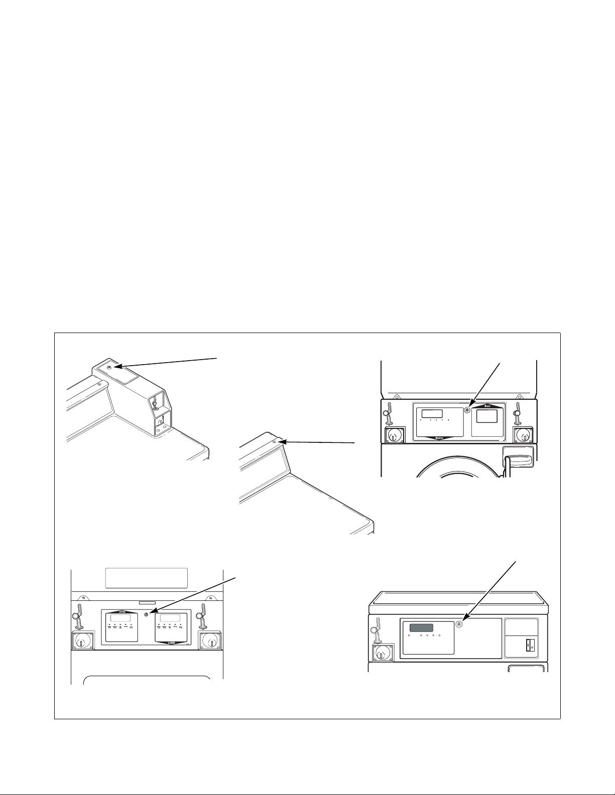
Opening the Service Door
FLW6R
3
2
1
OPERATING INSTRUCTIONS
Select Wash Temperature
HOT, WARM, COLD.
Select Fabric Type
NORMAL, PERM PRESS, DELICATE.
Load Supply Dispenser (See Instructions Below).
Load Clothes.
Insert Coin(s) / Card.
To Start Washer-Close Door and Push Start.
1.
2.
3.
4.
5.
6.
Open Dispenser Door.
Load Supplies in Proper
Compartment (as Indicated).
Close Dispenser Door.
1.
2.
3.
Detergent
Liquid Bleach
Fabric Softener
1.
2.
3.
DISPENSER INSTRUCTIONS
685942
DRY580R
INSERT
COIN/CARD
DOOR
LOCKED
WASH
RINSE SPIN
DOOR
LOCKED
SPINRINSEWASHINSERT
COIN / CARD
505617
1
1
Coin Rear Control Dryer
Stacked Washer and Dryer
Stacked Dryer
Front Control Dryer
1
1
DRY578R
DRY579R
DRY580R
Card Rear Control Dryer
W521I
1
FLW6R
Stacked Washers and Dryers, Stacked
Dryers, Front Control Dryers, and
Coin Rear Control Dryers
Manually programming the control requires the user to
open and close the service door. Opening and closing
the service door trips a switch allowing access to
various programming options, diagnostics, and audit
capabilities.
On stacked dryers, stacked washers and dryers, and
front control dryers, the service door is located in the
control panel. On rear control dryers, the service door is
located on the top of the meter case. Refer to Figure 2.
After opening and closing the service door, the
programmer has 4.25 minutes to begin programming.
If a SELECT CYCLE pad has not been pressed in that
time, the control will revert back to the Ready Mode.
Refer to Figure 2.
Rear Control Dryers with Card
Reader
Manually programming the control requires the user to
remove the control panel and unplug the bullet
connector located between the “white/black” and “red/
blue” wires or to insert an appropriate card into the
reader. This will allow the user to access various
programming options, diagnostics and audit
capabilities. The control panel is located on the control
hood. Refer to Figure 2.
1 Service Door
12
W521I
© Published by permission of the copyright owner – DO NOT COPY or TRANSMIT
Figure 2
513001

Entering the Manual Mode
>
<
For programming, testing, and retrieving information
from the control, it is often necessary to enter the
Manual Mode by following the four simple steps below.
For an overview of entering the manual mode, refer to
the flowchart on the following page.
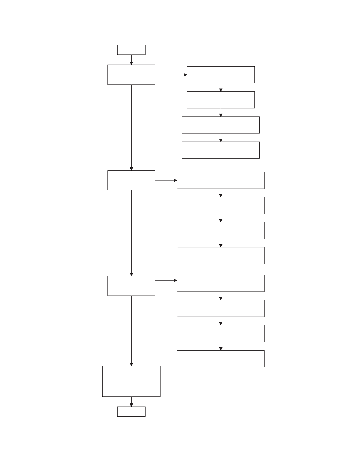
How to Enter the Manual Mode
1. If accessing Diagnostic Tests, be sure the dryer is
in the Ready Mode before continuing to step 2. If
the dryer is in an active cycle, rapid advance
through the cycle. Refer to Rapid Advance
Feature. If coins or a card has been entered, refer
to Clear Vend Feature.
2. Open the service door. Refer to Opening the
Service Door.
NOTE: Coin Models – The coin vault switch must
be closed to enter the Manual Mode. Card Reader
Models – Unplug bullet connector.
3. While pressing and holding the HIGH TEMP
keypad with one hand, press the MED TEMP
keypad with the other hand.
4. The display will show “rAPd”.
5. Press the LOW TEMP ( ) or the
DELICATES ( ) keypad to scroll through the
options until the desired option appears in the
display.
Manual Programming can only be turned on or off
with an external device or a network. Refer to the
appropriate instruction manual. Manual Rapid Advance
and Diagnostics can be turned on and off using an
external device by manual programming (refer to
options 30 and 31 of Programming Control), or with
the network.
By default, Manual Programming is turned “ON”.
The manual features available in each group are as
follows (the menu displayed on the display in this
mode is in parenthesis).
Rapid Advance (rAPd)
Manual Programming (Prog)
Manual Read Audit (AUdt)
Manual Reset (rSEt)
Diagnostic Tests (diAg)
If a manual parameter is turned off or unavailable (i.e.
attempting to enter diagnostics while a cycle is
running), the display will change from the selected
feature to “oFF”, an audio signal will sound for one
second and the features in the parameter cannot be
entered. The display will then return to the selected
feature.
6. Press the START (enter) keypad to enter the
displayed mode.
7. To exit, press the MED TEMP(<) keypad. The
control will revert back to Ready Mode.
513001
© Published by permission of the copyright owner – DO NOT COPY or TRANSMIT
13
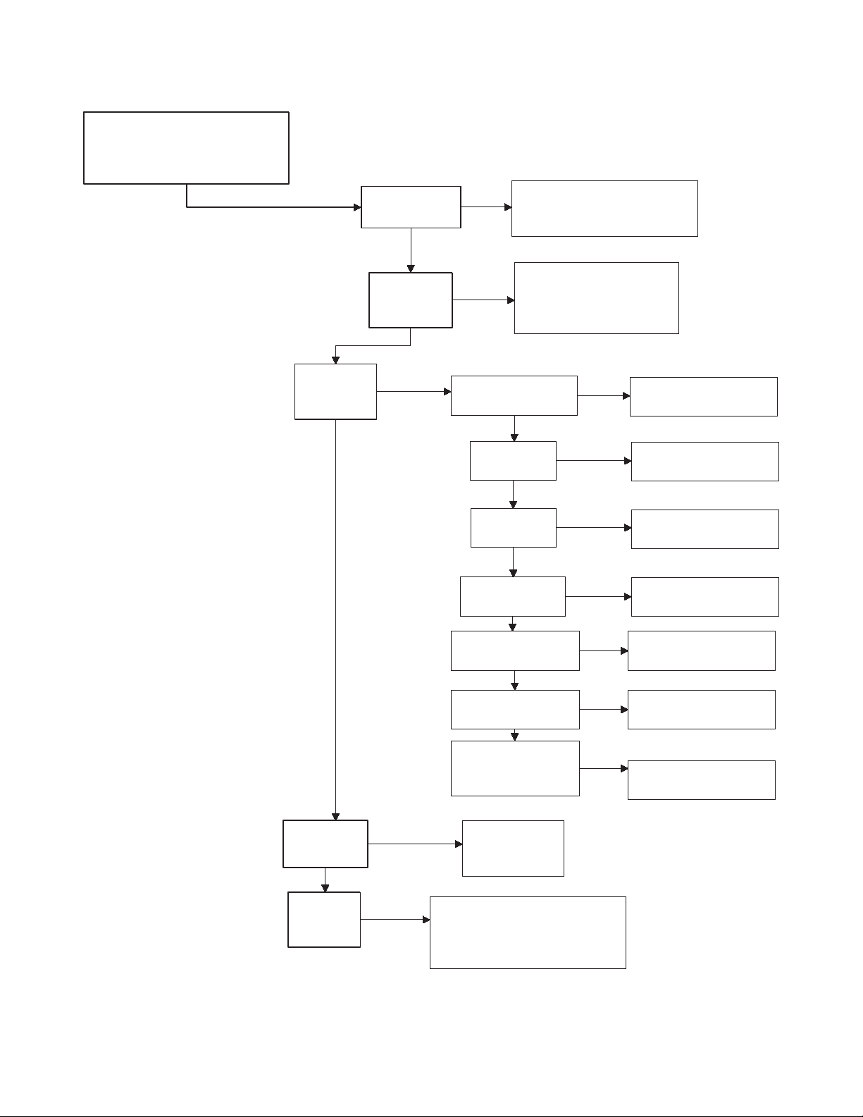
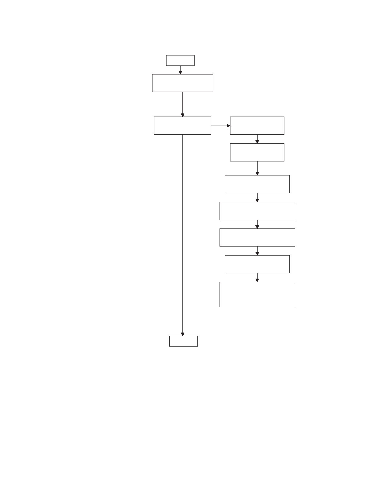
Entering the Manual Mode
Manual Mode : Enter by opening
and closing service door. Then
press HIGH TEMP and MED
TEMP keypads pads at same time.
"rAPd"
Rapid Advance
"Prog"
Manual
Programming
"AUdt"
Manual Read
Audit
"rSEt"
Manual Reset
"dIAg"
Diagnostic
Te st s
Press the LOW TEMP or
the DELICATES keypad
to scroll through the
Manual Mode options.
Press the START keypad to
begin Rapid Advance cycle and
to advance through cycle steps.
Press the START keypad to
enter Manual Programming.
Refer to Manual
Programming flowchart.
"CyC"
Total machine cycles
"Coi1"
Total coins #1
"PLSE"
Total start pulses
"Coi2"
Total coins #2
Press the
LOW TEMP
or the
DELICATES
keypad to
scroll through
the Audit
options.
Press the
START keypad.
Press the
START keypad
to reset control.
Press the START keypad to
enter Diagnostic Tests. Refer to
Diagnostic Tests flowchart.
DRY581R
Press the START (enter)
keypad to read audit.
Press the START (enter)
keypad to read audit.
Press the START (enter)
keypad to read audit.
Press the START (enter)
keypad to read audit.
"C1to"
Total coin 1 top-offs
"Pto"
Total start pulse/card
reader top-offs
"C2to"
Total coin 2 top-offs
Press the START (enter)
keypad to read audit.
Press the START (enter)
keypad to read audit.
Press the START (enter)
keypad to read audit.
To enter a programming option, press the
START keypad. To exit, press the MED
TEMP keypad.
14
© Published by permission of the copyright owner – DO NOT COPY or TRANSMIT
513001

Programming Control
What Can Be Programmed?
This feature allows the owner to program cycle
parameters, standard vend pricing, special vends, and
other features by using the keypads. The control must
have the Manual Programming Mode enabled, which is
the factory default. This mode can only be turned OFF
and ON by using an external device or a network.
Refer to this section when programming the control.
This section offers a detailed description of all
programmable options.
Each description includes instructions on when and
why the option might be used and, more importantly,
how to program the option.
For an overview of the programming organization,
refer to the flowcharts on the following pages.
For more advanced users, a quick reference list of the
options available through the programming mode is
located on this page.
NOTE: The codes in the Option column of the
Programmable Options List are what will show in
the display when that option is selected.
Programmable Options Available
Option
Number
1“AtSH” Heat Vend Price 200 0-65535
2“dEn1” Coin #1 Value 25 1-65535
3“dEn2” Coin #2 Value 100 1-65535
4“PLSE” Start Pulse Value 25 1-65535
5“PLSn” Start Pulse Mode 128 128 (on - single pulse),
6“AtyP” Available Type 0 ** 0-3; 0-7
7“dCyC” Default Cycle 4 1 (High Temp), 2 (Low Temp), 3 (No
8“oPL” OPL Mode oFF on/oFF
9“Aud” or
10 “CArd” Card Reader Display Control oFF on/oFF
11 “Err-”Errors – –
a“CEr-” Coin Error Parameters ––
12 “toP-” Top-Off Data – –
a“toP1” Top-Off on on/oFF
b“toP2” Coin 1 Top-Off Time Minutes 5 1-99
c“toP3” Coin 1 Top-Off Time Seconds 38 0-59
d“toP4” Coin 2 Top-Off Time Minutes 22 1-99
e“toP5” Coin 2 Top-Off Time Seconds 30 0-59
* “Aud” is displayed for Control Software version 01 and “AUd” is displayed for Control Software version 02 or later.
** 0-7 is available in software version “S 05” or higher only.
Option
Display
Audio 29 0-31
“AUd”*
1 “CEr1” Coin Error on on/oFF
2 “CEr2” Coin Error Penalty oFF on/oFF
3 “CEr3” Coin Drops Header Present Error on on/oFF
Description Default Value Value Range
192 (on - multiple pulses) or oFF
Heat), 4 (Med Temp), or 5 (Delicates)
513001
© Published by permission of the copyright owner – DO NOT COPY or TRANSMIT
15

Programming Control
Option
Number
Option
Display
Description Default Value Value Range
13 “CyC-”Cycle Time – –
a“CyC1” Heat Cycle Time Minutes 45 1-99
b“CyC2” Heat Cycle Time Seconds 0 0-59
c“CyC3” No Heat Cycle Time Minutes 45 1-99
d“CyC4” No Heat Cycle Time Seconds 0 0-59
14 “Cdt-” Cooldown Time – –
a“Cdt1” High Temp Cooldown Time 3 1-15
b“Cdt2” Medium Temp Cooldown Time 3 1-15
c“Cdt3” Low Temp Cooldown Time 3 1-15
d“Cdt4”
Delicates Temp Cooldown Time 3 1-15
15 “tEP-” Temperature – –
a“tEP1” High Temperature 160°F/71°C 100°-160°F/38°-71°C
b“tEP2” Medium Temperature 155°F/68°C 100°-160°F/38°-71°C
c“tEP3” Low Temperature 145°F/62°C 100°-160°F/38°-71°C
d“tEP4”
16 “t FC” Temperature
Delicates Temperature 115°F/46°C 100°-160°F/38°-71°C
0 0 (Fahrenheit)/1 (Celsius)
(Fahrenheit/Celsius)
17 “AtSn” No Heat Vend Price 200 0-65535
18 “rtC-”Real Time Clock – –
a“rtC1” Minutes – 0-59
b“rtC2” Hours – 0-23
c“rtC3”Day – 1-7
d“rtC4”Date – 1-31
e“rtC5” Month – 1-12
f“rtC6” Year – 0-99
g“rtC7” Daylight Savings on on/oFF
19 “SPA-” Special Vend A Data – –
a“SA01” Days Enable oFF on/oFF
b“SA02”Start Hour 0 0-23
c“SA03” Start Minute 0 0-59
d“SA04” Length in Hours 0 0-24
e“SA05” Start Month 0 0/1-12
f“SA06” Start Date 0 0/1-31
g“SA07” Start Year 0 0-99
h“SA08” End Month 0 0/1-12
i“SA09” End Date 0 0/1-31
j“SA10” End Year 0 0-99
k“SA11” Heat Price 0 0-65535
l“SA12” No Heat Price 0 0-65535
m“SA13” Heat Time Minutes 1 1-99
n“SA14” No Heat Time Minutes 1 1-99
o“SA15” Coin #1 Top-Off Time Minutes 1 1-99
p“SA16” Coin #2 Top-Off Time Minutes 1 1-99
16
© Published by permission of the copyright owner – DO NOT COPY or TRANSMIT
513001

Programming Control
Option
Number
Option
Display
Description Default Value Value Range
20 “SPb-” Special Vend B Days Enable oFF on/oFF
21 “SPC-” Special Vend C Days Enable oFF on/oFF
22 “SPd-” Special Vend D Days Enable oFF on/oFF
23 “droP” Drop Off Mode oFF on/oFF
24 “LPSA” Low Power/Auto Shutdown A
oFF on/oFF
Days Enable
25 “LPSb” Low Power/Auto Shutdown B
oFF on/oFF
Days Enable
26 “LPSC” Low Power/Auto Shutdown C
oFF on/oFF
Days Enable
27 “LPSd” Low Power/Auto Shutdown D
oFF on/oFF
Days Enable
28 “PFr” Power Fail Reset oFF on (133 [5 minutes] - 255
[127 minutes])/oFF
29 “IrA” IR Access on on/oFF
30 “rAEn” Manual Rapid Advance on on/oFF
31 “dAEn” Manual Diagnostics on on/oFF
32 “PtEn” Production Test Cycle on on/oFF
513001
© Published by permission of the copyright owner – DO NOT COPY or TRANSMIT
17
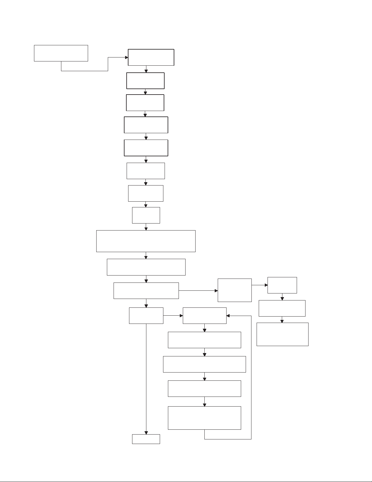
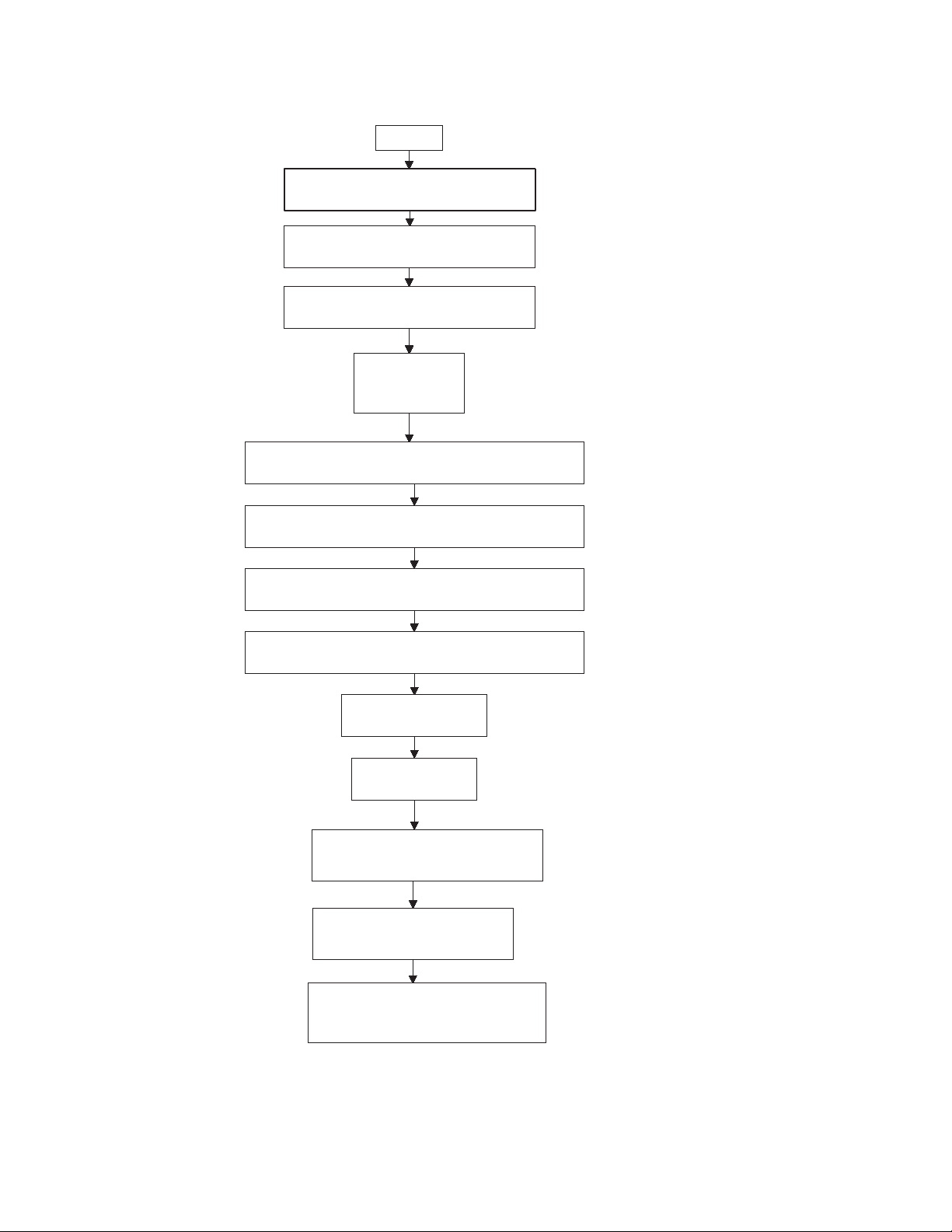
Programming Control
"Prog"
Manual Programming
Press the
START keypad.
Press the LOW
TEMP or the
DELICATES keypad
to scroll through the
programmable
options.
"AtSH"
Heat Vend Price
"dEn1"
Coin #1 Value
"dEn2"
Coin #2 Value
"PLSE"
Start Pulse Value
"PLSn"
Start Pulse Mode
"AtyP"
Available Type
"dCYC"
Default Cycle
"oPL"
OPL Mode
To enter a programming
option, press the START
keypad. To exit, press
the MED TEMP keypad.
"Aud" or "AUd"
Audio Signal
(depending on control software version)
"CArd"
Card Reader Display Control
"Err"
Error Code Programming
"toP-"
Top-Off Data
Top-Off On/Off
Coin 1 Top-Off Time Minutes
Coin 1 Top-Off Time Seconds
Coin 2 Top-Off Time Minutes
Coin 2 Top-Off Time
"toP1"
"toP2"
"toP3"
"toP4"
"toP5"
Seconds
"CEr-"
Coin Error
Parameters
"CEr1"
Coin Error
"CEr2"
Coin Error Penalty
"CEr3"
Coin Drops Header
Present Error
18
continued
© Published by permission of the copyright owner – DO NOT COPY or TRANSMIT
DRY582R-a
513001
Programming Control
DRY582R-b
continued
"CyC-"
Cycle Time
"CyC1"
Heat Cycle Time Minutes
"CyC2"
Heat Cycle Time Seconds
"CyC3"
No Heat Cycle Time Minutes
"CyC4"
No Heat Cycle Time Seconds
"Cdt-"
Cool Down Time
"Cdt1"
High Temp Cooldown Time
"Cdt2"
Medium Temp Cooldown Time
"Cdt3"
Low Temp Cooldown Time
"Cdt4"
Delicates Cooldown Time
"tEP-"
Temperature
"tEP1"
High Temperature
"tEP2"
Medium Temperature
"tEP3"
Low Temperature
"tEP4"
Delicates Temperature
"t FC"
Temperature
(Fahrenheit/Celsius)
continued
Press the LOW
TEMP or the
DELICATES keypad
to scroll through the
programmable
options.
To enter a programming
option, press the START
keypad. To exit, press
the MED TEMP keypad.
513001
© Published by permission of the copyright owner – DO NOT COPY or TRANSMIT
19
Programming Control
Press the LOW
TEMP or the
DELICATES keypad
to scroll through the
programmable
options.
continued
"AtSn"
No Heat Vend Price
To enter a programming
option, press the START
keypad. To exit, press
the MED TEMP keypad.
"rtC-"
Set Real-Time Clock
"rtC1"
Programs Minutes
"rtC2"
Programs Hours
"rtC3"
Programs Day of Week
"rtC4"
Programs Date of Month
"rtC5"
Programs Month
"rtC6"
Programs Year
"rtC7"
Programs Daylight Savings
20
continued
© Published by permission of the copyright owner – DO NOT COPY or TRANSMIT
DRY582R-c
513001

DRY582R-d
Press the LOW
TEMP or the
DELICATES keypad
to scroll through the
Special Vend options.
"SPA-"
Special Vend A data
To enter a
special vend
option, press the
START keypad.
To exit, press
the MED TEMP
keypad.
"SA01"
Special Vend A Days Enable
continued
continued
"SA02"
Special Vend A Start Hour
"SA03"
Special Vend A Start Minute
"SA04"
Special Vend A Length in Hours
"SA05"
Special Vend A Start Month
"SA06"
Special Vend A Start Date
"SA07"
Special Vend A Start Year
"SA08"
Special Vend A End Month
"SA09"
Special Vend A End Date
"SA10"
Special Vend A End Year
"SA11"
Special Vend A Heat Price
"SA12"
Special Vend A No Heat Price
"SA13"
Special Vend A Heat Time Minutes
"SA14"
Special Vend A No Heat Time Minutes
"SA15"
Special Vend A Coin #1 Top-Off Time Minutes
"SA16"
Special Vend A Coin #2 Top-Off Time Minutes
Programming Control
513001
© Published by permission of the copyright owner – DO NOT COPY or TRANSMIT
21
Programming Control
DRY582R-e
"SPb-"
Special Vend B Days Enable (On/Off)
Press the LOW TEMP
or the DELICATES
keypad to scroll through
the programmable
options.
To enter a programming
option, press the START
keypad. To exit, press
the MED TEMP keypad.
continued
"SPC-"
Special Vend C Days Enable (On/Off)
"SPd-"
Special Vend D Days Enable (On/Off)
"droP"
Drop Off Mode
(On/Off)
"LPSA"
Low Power/Auto Shutdown A Days Enable (On/Off)
"LPSb"
Low Power/Auto Shutdown B Days Enable (On/Off)
"LPSC"
Low Power/Auto Shutdown C Days Enable (On/Off)
"LPSd"
Low Power/Auto Shutdown D Days Enable (On/Off)
"PFr"
Power Fail Reset
"IrA"
IR Access (On/Off)
"rAEn"
Manual Rapid Advance (On/Off)
"dAEn"
Manual Diagnostics (On/Off)
"PtEn"
Production Test Cycle (On/Off)
22
© Published by permission of the copyright owner – DO NOT COPY or TRANSMIT
513001
 Loading...