

Huebsch HD170 Tumbler-Dryer Parts Diagram

Drying Tumblers
170 Pound Capacity
Refer to Page 3 for Model Numbers
Parts
www.alliancelaundry.com
Part No. D1027R2
November 2013


Table of Contents
Title Page
Parts Ordering Information........................................................................................................................................ 2
Serial Plate Location ................................................................................................................................................. 2
Model Identification ................................................................................................................................................... 3
2 Timer Control Panel Assembly .............................................................................................................................. 4
DMP Control Panel Assembly................................................................................................................................... 6
Pro and ProHC Control Panel Assembly .................................................................................................................. 8
Front Panel Assembly ............................................................................................................................................. 10
Front View ............................................................................................................................................................... 12
Burner Access Door ................................................................................................................................................ 14
Lint Door Assembly ................................................................................................................................................. 16
Gear Motor Rear View ............................................................................................................................................ 18
Air Switch Assembly ............................................................................................................................................... 20
Rear Motor Control Assembly................................................................................................................................. 22
TM200 Gear Reducer - Rear View ......................................................................................................................... 24
TM200 Large Gear Reducer with Bronze Teeth ..................................................................................................... 26
Fan Assembly ......................................................................................................................................................... 28
Thermostat Assembly - 2 Timer.............................................................................................................................. 30
2 Timer Sensor Assembly ....................................................................................................................................... 32
DMP Sensor Assembly ........................................................................................................................................... 34
Pro Sensor Assembly ............................................................................................................................................. 36
ProHC Sensor Assembly - Upper Assembly........................................................................................................... 38
ProHC Sensor Assembly - Lower Assembly........................................................................................................... 40
Gas Bonnet Assembly ............................................................................................................................................ 42
Steam Bonnet Assembly......................................................................................................................................... 44
Insulation Placement............................................................................................................................................... 46
Parts Index .............................................................................................................................................................. 49
© Copyright 2013, Alliance Laundry Systems LLC
All rights reserved. No part of the contents of this book may be reproduced or transmitted in any form or by any
means without the expressed written consent of the publisher.
D1027 1
© Copyright, Alliance Laundry Systems LLC – DO NOT COPY or TRANSMIT

Parts Ordering Information
If literature or replacement parts are required, contact the source from whom the machine was purchased or contact Alliance Laundry Systems at
(920) 748-3950 for the name and address of the
nearest authorized parts distributor.
Serial Plate Location
When calling or writing about your product, be
sure to mention model and serial numbers. Model
and serial numbers are located on serial plates.
For technical assistance, call either of the numbers listed below:
(920) 748-3121 Ripon, Wisconsin
+32 56 41 20 54 Wevelgem, Belgium
D1027 2
© Copyright, Alliance Laundry Systems LLC – DO NOT COPY or TRANSMIT

Model Identification
Information in this manual is applicable to these tumbler models:
HD170
D1027 3
© Copyright, Alliance Laundry Systems LLC – DO NOT COPY or TRANSMIT
2 Timer Control Panel Assembly
TMB2812P_D1027
4 D1027
© Copyright, Alliance Laundry Systems LLC – DO NOT COPY or TRANSMIT

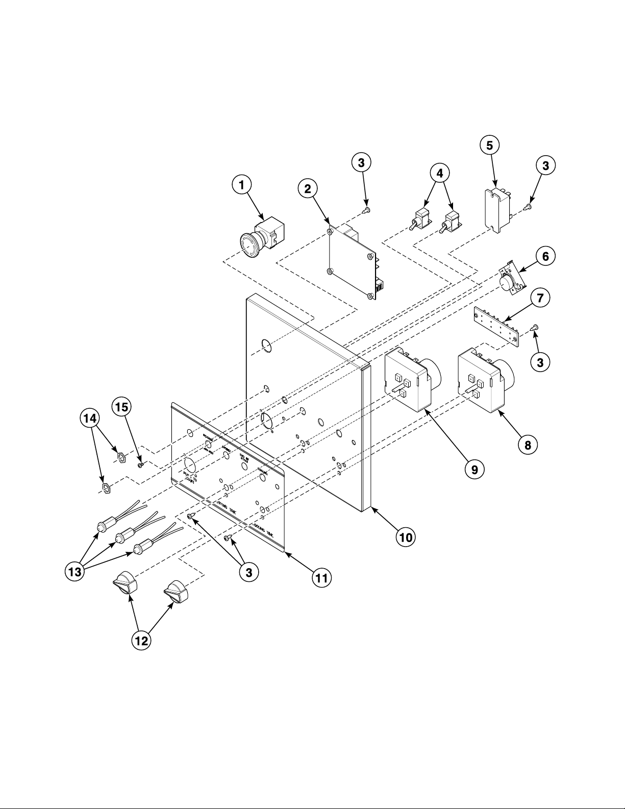
2 Timer Control Panel Assembly
REF PART NO. DESCRIPTION COMMENTS
1 TU14435 Emergency Stop Button Kit 50 Hertz
1 TU15724 Button Plug 7/8 inch; 60 Hertz
2 TU12874P Reversing Timer
3 TU7733 Screw No. 8-18 x 1/2 inch; Self-drilling
4 FG147P Toggle Switch
5 F1300P Relay 24 Volt
6 TU9028 Pushbutton Switch
7 TU8629 Terminal Board
8 TU12933P Timer 0-15 minutes
9 TU12932P Timer 0-60 minutes
10 TU15406WHT Control Panel Weldment Assembly
11 TU15459 2 Timer Nameplate
12 TU2555 Knob
13 TUT316 LED Light Assembly 24 Volt
14 TU3805 Nut No. 15-32; Hex
15 ET208 Screw No. 6-32 x 1/4 inch; Binding head
D1027 5
© Copyright, Alliance Laundry Systems LLC – DO NOT COPY or TRANSMIT
DMP Control Panel Assembly
TMB2435P_D1027
6 D1027
© Copyright, Alliance Laundry Systems LLC – DO NOT COPY or TRANSMIT

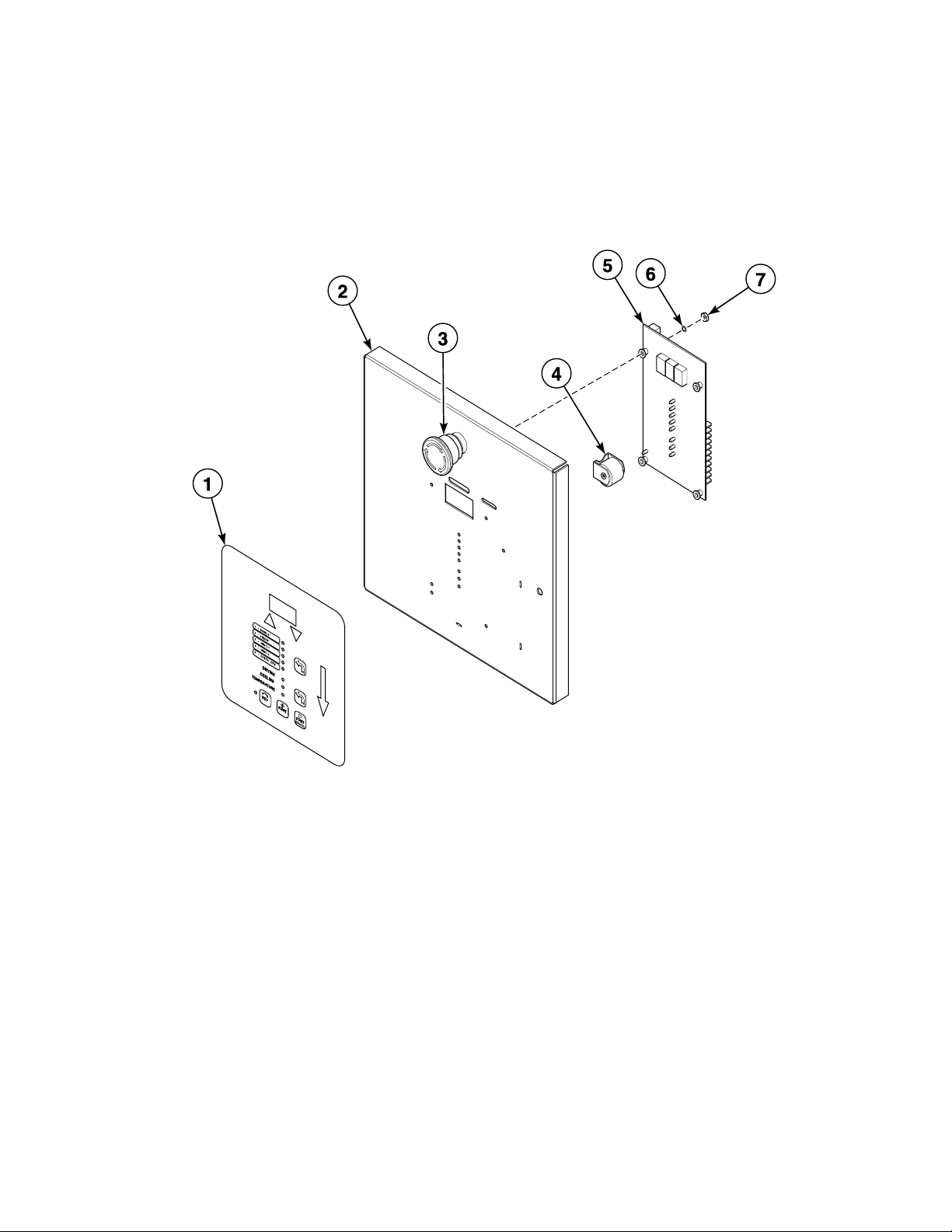
DMP Control Panel Assembly
REF PART NO. DESCRIPTION COMMENTS
1 44037901P Membrane Switch OPL DMP; Right side; Down
2 TU14469WHT DMP Control Panel Weldment Assembly
3 TU14435 Emergency Stop Button Kit 50 Hertz
3 TU15724 Button Plug 7/8 inch; 60 Hertz
4 TU14137 Buzzer 24 Volt
5 TU14404P Controller OPL/Coin board; New
6 M270 Washer No. 6; Internal tooth lock
7 TU3400 Nut No. 6-32; Hex
D1027 7
© Copyright, Alliance Laundry Systems LLC – DO NOT COPY or TRANSMIT
Pro and ProHC Control Panel Assembly
TMB2888P_D1027
8 D1027
© Copyright, Alliance Laundry Systems LLC – DO NOT COPY or TRANSMIT

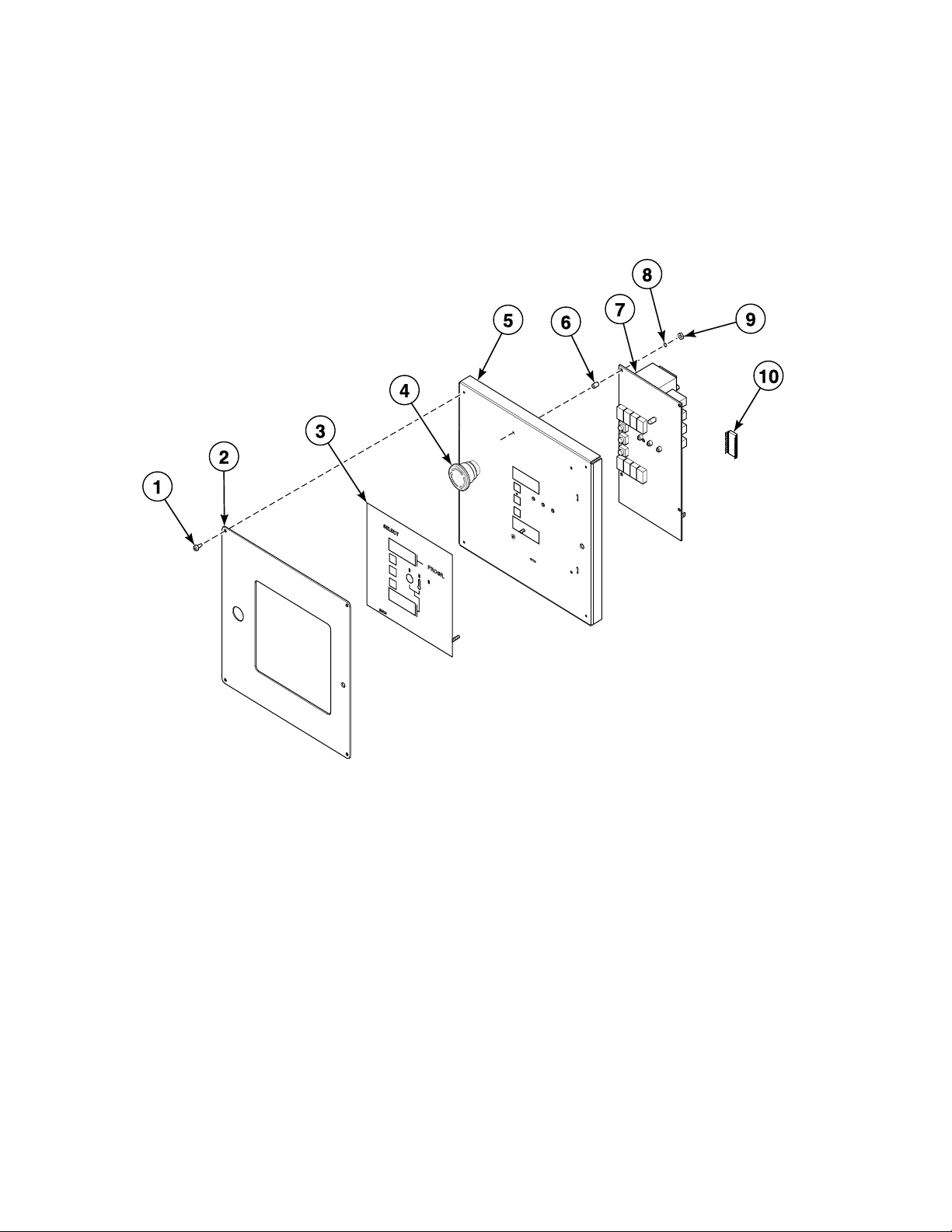
Pro and ProHC Control Panel Assembly
REF PART NO. DESCRIPTION COMMENTS
1 M261 Screw No. 8-32
2 TU14727WHT Control Panel Cover Plate
3 254/00039/00 Operating Touchpad Pro control
3 254/00018/00 Control Label ProHC control
4 TU14435 Emergency Stop Button Kit 50 Hertz
4 TU15724 Button Plug 7/8 inch; 60 Hertz
5 TU14442WHT Control Cover Assembly
6 N/A Spacer
7 254/00070/00P Control Board
8 M270 Washer Lock
9 TU3400 Nut No. 6-32
10 N/A EPROM Chip Standard program
N/A = Part no longer available
D1027 9
© Copyright, Alliance Laundry Systems LLC – DO NOT COPY or TRANSMIT
Front Panel Assembly
TMB2424P_D1027
10 D1027
© Copyright, Alliance Laundry Systems LLC – DO NOT COPY or TRANSMIT

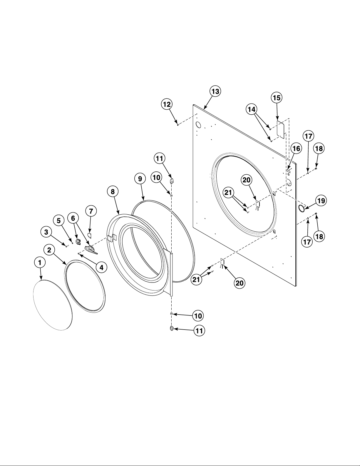
Front Panel Assembly
REF PART NO. DESCRIPTION COMMENTS
NA TU6030 Temperature Control Assembly See detail
1 TU15107P Door Glass 20 1/4 inch
2 TU15966 Door Gasket
3 TU2687 Screw No. 8; Phillips head
4 JA-51604 Screw No. 8-32; Pan head
5 F431106 Washer No. 8; E.T. cup
6 TUA2319H Door Latch Includes keeper
7 TU5503 Door Latch Spacer
8 TU14467WHT Door Basket Specify color
9 TU5288P Door Seal
10 PIF172 Hinge Bushing
11 TU2236 Hinge Post
12 TU3209 Screw No. 14; Pan head
13 TU15448WHT Front Panel Assembly Specify color
14 TU7733 Screw No. 8 x 1/2 long
15 TU15525WHT Front Panel Cover Plate Specify color; For DMP and ProHC
16 TU5458 Temperature Nameplate
17 202010 Washer 5/16; Lock
18 TU2836 Screw 5/16-18; Hex head
19 TU2641 Thermometer Gasket
20 ESA-00862-0P Reed Switch Assembly
21 SB-00975-0 Screw No. 6-32
D1027 11
© Copyright, Alliance Laundry Systems LLC – DO NOT COPY or TRANSMIT
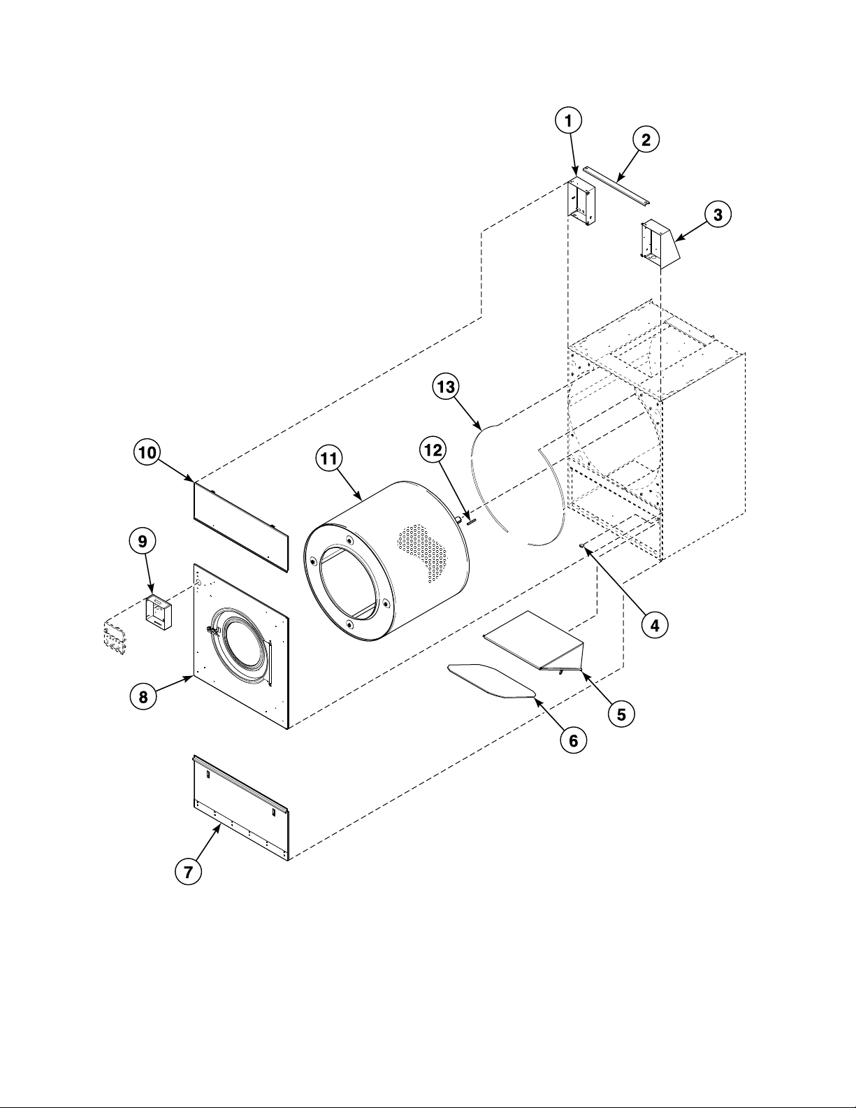
Front View
TMB2419P_D1027
12 D1027
© Copyright, Alliance Laundry Systems LLC – DO NOT COPY or TRANSMIT

Front View
REF PART NO. DESCRIPTION COMMENTS
1 N/A Left Hand Control Box Assembly Specify color
2 N/A Control Box Support
3 N/A Right Hand Control Box Assembly Specify color
4 EA-11621-0 Lint Door Switch
5 TU10345 Lint Screen Housing
6 K121 Lint Trap Frame Kit
6 K368 Lint Screen Kit
7 N/A Lint Door Assembly
8 N/A Time/Temperature Front Panel Assembly Specify color
9 N/A Control Box Specify color; Includes hardware
10 N/A Burner Access Door Assembly Specify color
11 K325 Basket Assembly Kit Includes spider; Galvanized; TM200 Gear Reducer
11 N/A Basket Assembly Includes spider; Stainless steel; TM200 Gear Reducer
11 N/A Basket and Spider Assembly Galvanized; Gear motor
11 N/A Basket and Spider Assembly Includes spider; Stainless steel; Gear motor
11 TU9609 Basket Galvanized; Without spider
11 N/A Basket Stainless steel; Without spider
11 K321 Spider Kit Without basket; TM200 Gear Reducer
11 TU16027 Spider Assembly Without basket; Gear motor
12 TU9975 Key TM200 Gear Reducer
12 N/A Key Gear motor
13 K118 Gasket Kit
N/A = Part no longer available
D1027 13
© Copyright, Alliance Laundry Systems LLC – DO NOT COPY or TRANSMIT
TMB2889P_D1027
FRONT
VIEW
REAR
VIEW
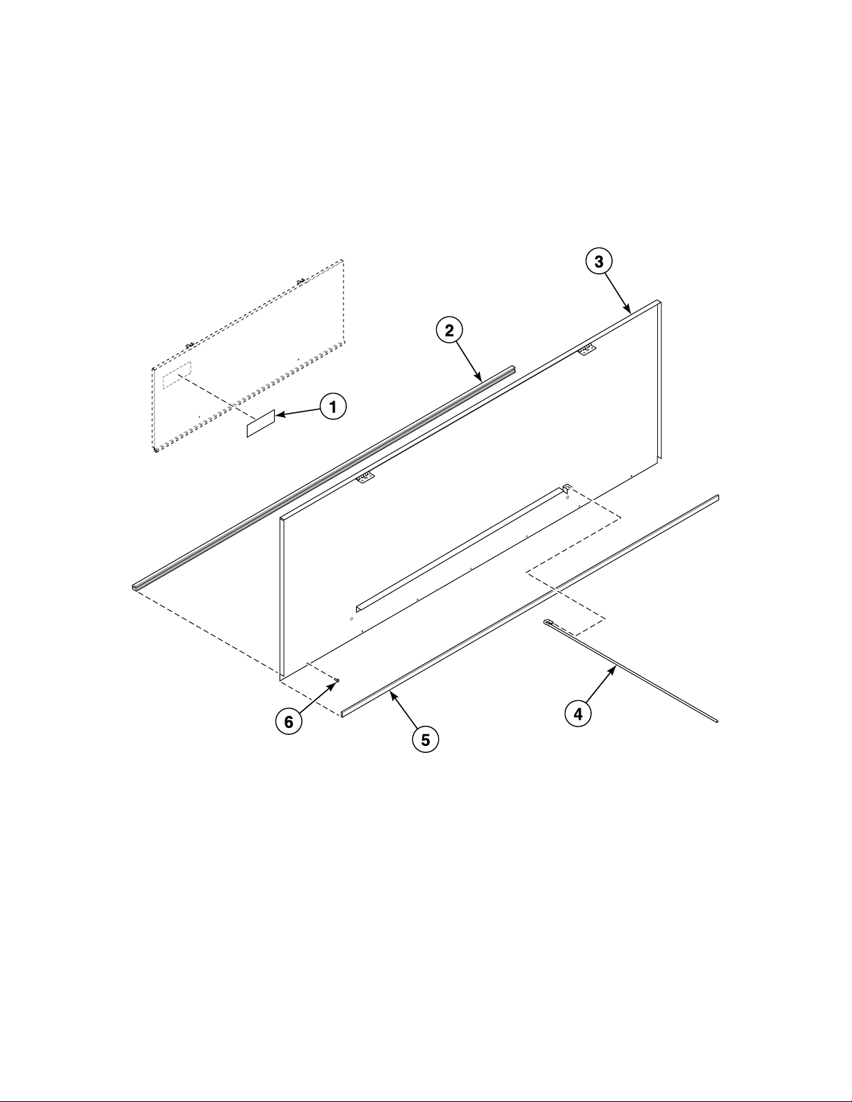
Burner Access Door
14 D1027
© Copyright, Alliance Laundry Systems LLC – DO NOT COPY or TRANSMIT

Burner Access Door
REF PART NO. DESCRIPTION COMMENTS
1 TU14662 Decal
2 N/A Burner Access Door Trim
3 TU14622WHT Access Door Weldment Assembly Specify color
4 TU5739 Support Arm Rod
5 CA-13098-0 Control Door Gasket
6 SB-00951-0 Screw No. 8 x 7/16 inch; Phillips flat head
N/A = Part no longer available
D1027 15
© Copyright, Alliance Laundry Systems LLC – DO NOT COPY or TRANSMIT
 Loading...