

Page 1

HA35 Hybrid Access Gateway
User Guide
Version 2.1 (May 2016)
Page 2

Contents
Product Overview .............................................................6 1.
1.1. Supported Features .................................................................... 6
1.2. Ports and Buttons........................................................................ 7
1.3. Indicators .................................................................................... 8
Hardware Installatio n ..................................................... 11 2.
2.1. Selecting an Installation Location .............................................. 11
2.2. Installing the HA35 on a Hybrid Broadband Network ................ 12
2.2.1. PSTN or Broadband Telephone Line with one voice
channel and a 3G/4G connection .................................... 12
2.2.2. ISDN Line and 3G/4G connection .................................... 13
2.2.3. Broadband Telephone Line with the intervention of an
electrician in the internal home wiring (i.e. legacy ISDN
wiring) and a 3G/4G connection ...................................... 14
2.3. Installing the HA35 on a DSL Broadband Network .................... 15
2.3.1. PSTN or Broadband Telephone Line with one voice
channel ........................................................................... 15
2.3.2. ISDN Line ......................................................................... 16
2.3.3. Broadband Telephone Line with the ntervention of an
electrician in the internal home wiring (i.e. legacy ISDN
wiring) ............................................................................. 17
2.4. Installing the HA35 on a 3G/4G Network .................................. 18
2.5. Powering On ............................................................................. 19
Setting Network Parameters .........................................20 3.
3.1. Setting the Computer IP Address .............................................. 20
3.1.1. Obtain an IP address automatically .................................. 20
3.1.2. Set a static IP address ...................................................... 22
3.2. Logging In to the Web Management Page ................................ 23
3.3. Setting Network Access Parameters ......................................... 24
3.3.1. Accessing the Network through the Hybrid gateway ......... 24
3.3.2. Accessing the Network through DSL ................................ 28
Version 2.1 (May 2016) 2
Page 3

3.3.3. Accessing the Network through the SIM card ................... 29
3.4. Configuring a Wireless Account ................................................ 31
3.5. Check My Network Status ......................................................... 31
Wireless Connection Setu p...........................................33 4.
4.1. Setting Up a Wireless Connection Using the WPS Button ........ 33
4.2. Manually Setting Up a Wireless Connection ............................. 34
4.2.1. On Windows 7 .................................................................. 34
WLAN Configuration ......................................................35 5.
5.1. Enabling and Disabling the WLAN on the HA35 ....................... 35
5.1.1. Using the WLAN Button .................................................... 35
5.1.2. Using the Web Management Page ................................... 35
5.2. Changing Your WLAN Name and Password ............................. 35
5.3. WLAN Advanced Settings ......................................................... 36
Network Security ............................................................37 6.
6.1. Improving WLAN Security ......................................................... 37
6.1.1. Hiding the WLAN Name ................................................... 37
6.1.2. Using High Security Encryption Modes ............................ 38
6.1.3. Enable the WPS Function ................................................ 38
6.2. Allowing Only Specified Computers to Access Your WLAN ....... 41
6.3. Controlling Computer Internet Access ....................................... 42
6.4. Filtering Out Inappropriate Websites ......................................... 43
6.5. Configuring the Firewall ............................................................ 45
6.5.1. Recommended Firewall Level .......................................... 45
6.5.2. Configuring the Firewall .................................................... 45
6.6. Configure an ACL ...................................................................... 46
6.7. Configure DMZ .......................................................................... 48
6.8. Configure Application Filter ....................................................... 48
6.9. Configure Port Forwarding ........................................................ 50
6.9.1. Configure Port Mapping .................................................... 50
6.9.2. Configure Port Trigger ...................................................... 52
Version 2.1 (May 2016) 3
Page 4

Internet Services ............................................................53 7.
7.1. Dynamic DNS ........................................................................... 53
7.2. Simple Network Time Protocol .................................................. 54
7.3. Multicast management .............................................................. 55
IP T elephony ...................................................................56 8.
8.1. Introduction to IP Telephony ...................................................... 56
8.2. Configuring VoIP ....................................................................... 56
8.3. Placing a VoIP Call .................................................................... 58
USB Device .....................................................................59 9.
9.1. USB Storage Device ................................................................. 59
9.2. You can connect a USB storage device to your HA35 and access
the USB device from your computer. ....................................... 59
9.3. Connecting a USB Device ......................................................... 59
9.3.1. Setting the FTP Access Permission .................................. 59
9.3.2. Accessing to FTP Server Through the User Name and
Password ........................................................................ 59
9.3.3. Accessing a USB Storage Device Using FTP ................... 61
9.3.4. Setting the Samba Access Permission ............................. 61
9.3.5. Accessing Data Using Samba .......................................... 63
9.4. Configuring Multimedia Sharing ................................................ 63
9.5. Sharing a USB Printer ............................................................... 64
9.5.1. On Windows 7 .................................................................. 64
Maintenance Guide ......................................................65 10.
10.1. Changing the IP Address Used to Log In to the Web
Management Page .................................................................. 65
10.2. Setting the DHCP Server IP range .......................................... 65
10.3. RA Settings ............................................................................. 66
10.4. IPv6 DHCP Server .................................................................. 67
10.5. Changing the Web Management Page Password ................... 67
10.6. Rebooting Device .................................................................... 68
10.7. Restoring Default Settings ...................................................... 69
Version 2.1 (May 2016) 4
Page 5

10.7.1. Using the Reset Button ................................................... 69
10.7.2. Using the Config ur ati o n Tool ........................................... 69
10.8. Upgrading Firmware ................................................................ 69
10.9. Using Ping Tool Diagnose Network ......................................... 70
10.10. Using Tracert Tool Diagnose Network ................................... 71
Reference Operations ..................................................72 11.
11.1. Setting Dial-Up Connection Parameters .................................. 72
11.2. Enabling Wireless Configuration on Windows ......................... 75
11.3. Checking the Computer MAC Address .................................... 75
FAQs ..............................................................................77 12.
12.1. What Can I Do If I Cannot Open the Web Management Page?
................................................................................................ 77
12.2. What Can I Do If the HA35 Cannot Access the Internet through
a Wireless Network Adapter Sometimes or If the WLAN
Connection Is Unsteady? ........................................................ 77
12.3. What Can I Do If I Cannot Access the Internet? ...................... 77
12.4. I Often Need to Restart the HA35 to Display Web Pages. What
Can I Do? ................................................................................ 79
12.5. What Is the Difference Between Wireless MAC Address
Filtering and MAC Address Filtering? ...................................... 79
12.6. Can I Change the WLAN Password? ...................................... 79
Appendix .......................................................................80 13.
13.1. Technical Sp ec ifi cati ons .......................................................... 80
13.2. Default Settings ....................................................................... 81
For More Help ...............................................................82 14.
Legal Notice ..................................................................83
Acr ony ms and Abbre viat ions .....................................85
List of Pictures .............................................................87
List of Tables ................................................................92
Version 2.1 (May 2016) 5
15.
16.
17.
18.
Page 6

Product Overview 1.
1.1. Supported Features
The HA35 Hybrid Access Gateway (HA35 for short) is a high-speed wireless router
designed for home and small o ffice use. Thi s chapter d escribes t he featur es supported by
the HA35.
Digital subscribe r line (DSL) provid es rugged stabilit y, and with the Wi-Fi Protected
Setup (WPS) button , zero configuration is required for connec tio ns to multiple devices.
Network range allows any device in a home to be connected with a wireless
transmission rate of up to 30 0 Mbps.
A powerful firewall is provided with a flexible network configuration and quality of
service (QoS) strategy, enabling different home devices to enjoy high-speed and highquality broadband services.
High-Bandwidth DSL Connectivity
The HA35 incorpo rates a hig h-performanc e ADSL2+/ VDSL2 proc essor and provides hi ghspeed Internet ac cess a nd ab unda nt s ervic es to b e deli vere d thro ugh t he digi tal su bsc riber
line (DSL).
Routing
The HA35 supports ro uting. It can obtain an IP add ress through PPP dial-up or D ynamic
Host Configuration Protocol (DHCP), which provides simultaneous access for multiple
devices.
WLAN
The HA35 support s multiple WLAN protoc ols, including 802.11b/g/n (2.4 GHz ). Adopting
802.11n multiple-input multiple -output antennas (MIMO) techn ology, the HA35 delive rs a
wireless transmissi on rate of up t o 300 Mbps with its dual a ntennas. In addition, t he HA35
supports multipl e wireless encrypt ion modes to pr ovide a secure, reliabl e, and high-speed
WLAN.
Bandwidth Control
The HA35 supports bandwidth control and allocates bandwidth to different computers
within your hom e based on Internet access requirem ents. Your family can then a ccess t he
Internet, play online gam es , and watch videos without interfering with each other.
Wi-Fi Protected Setup
You can set up wireless con nections between the HA35 a nd Wi-Fi enabled devices b y
pressing the WPS button.
Firewall
The powerful built-in firewall effectively protects against viruses and malicious attacks.
Version 2.1 (May 2016) 6
Page 7
1
3 4 5 6 8
9
10
72
Parental Controls
Parents can control their children's computer usage by placing time limits on usage
duration or forbidding access to certain websites.
Easy Configuration and Management
The HA35 provides password-protected web-based management pages to protect your
personal data.
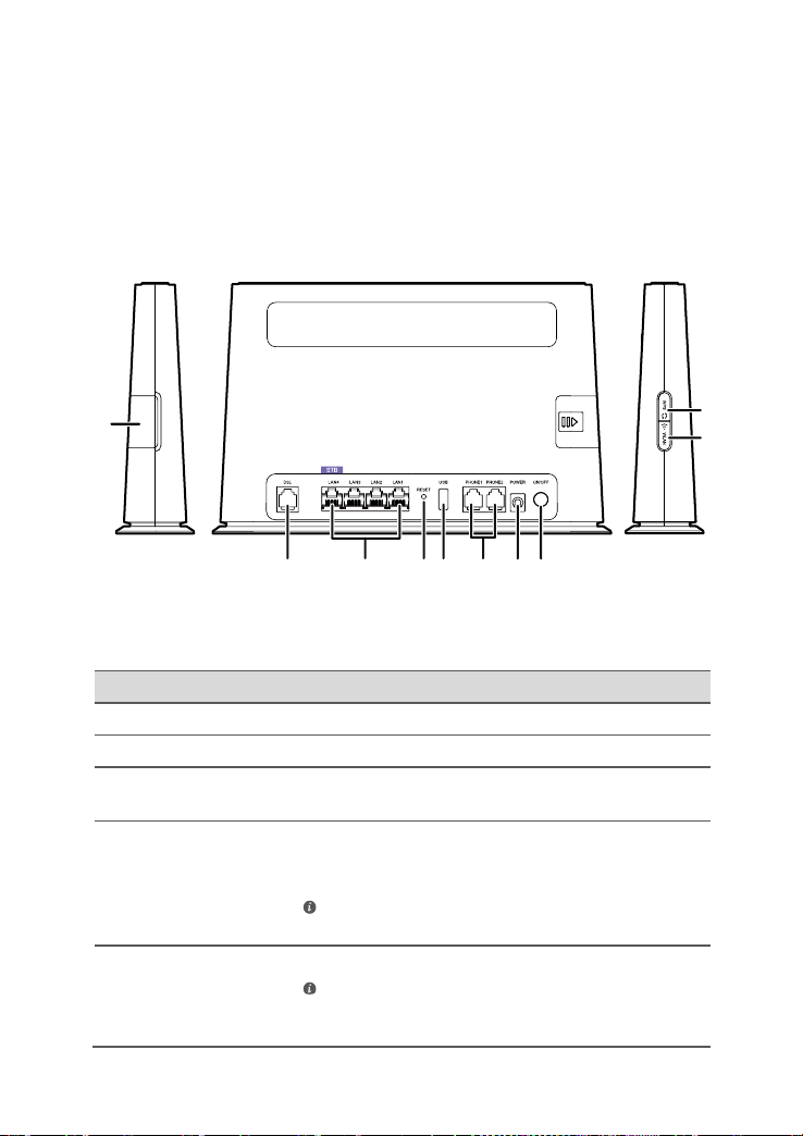
1.2. Ports and Buttons
Picture 1-1 ports and buttons
No. Item Description
1 SIM Inserts a SIM card.
2 DSL Connects to a DSL filter or phone socket.
3 LAN1–LAN4 Connects to Ethernet devices , such as computers, set-top
4 RESET Restores the HA3 5 to its default settings aft er you press
5 USB Connects to a USB 2.0 device.
boxes (STBs), and switches.
and hold this butto n for 6 s econds o r more while the H A35
is powered on.
A reset will result in all custom data and settings being lost.
Use with caution.
If yo u connect a USB device to t he HA35, verify that the
input voltage and current of the USB device does not exceed
5 V/0.5 A. Otherwise, the HA35 may malfunction.
Version 2.1 (May 2016) 7
Page 8
No. Item Description
6 PHONE1–
PHONE2
7 POWER Connects to a power adapter.
8 ON/OFF Powers the HA35 on or off.
9 WLAN Enables or disables the WLAN function.
10 WPS Starts Wi-Fi protected setup (WPS) negotiation.
Connects to a telephone.
Table 1-1 ports and buttons
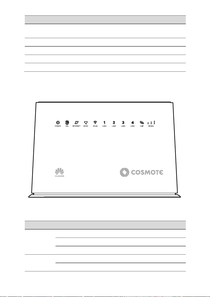
1.3. Indicators
Picture 1-2 front side
Indicator Status Description
POWER Green on The HA35 is powered on.
Red Blinking Self-checking failed after the HA35 is powered on.
Off The HA3 5 is pow er ed off or faulty.
DSL Green on The HA35 is activated through DSL.
Green Blinking The HA35 is being activated through DSL.
Version 2.1 (May 2016) 8
Page 9

Indicator Status Description
Off The DSL port is not activated successfully.
The HA35 is powered off.
INTERNET Green on The HA35 is working in routing mode.
No data is being transmitted.
Green Blinking The HA35 is co nnected to the Internet, and dat a is
being transmitted.
Off The HA35 is working in routing mode, but the
connection has not been set up.
The HA35 is powered off.
MODE Steady on Cyan: the HA35 is registered to the LTE network.
Blue: the HA35 is registered to the WCDMA network.
Red Blinking There is no SIM card or the SIM card is faulty.
The SIM card is locked.
The SIM card is unavailable.
Off There is no wireless service.
The HA35 is powered off.
WLAN Green on The WLAN connection is set up, but n o data is being
transmitted.
Green Blinking The WLAN connec tion is set up, and data is bei ng
transmitted.
The WPS is in InProgress or Error status.
Off The WLAN function is disabled.
The HA35 is powered off.
LAN1–LAN4 Green on The HA35 is connected to a device properly.
Green Blinking Data is being transm itte d bet ween the HA35 a nd the
connected device.
Off No connection is set up on the port.
The HA35 is powered off.
VoIP G re en on The HA35 is regi ster ed wi th a S IP (S essi on Initi atio n
Protocol) server, but no data is being transmitted.
Green Blinking The HA35 is registering with a SIP server.
The VoIP connection is set up, and data is being
transmitted.
Version 2.1 (May 2016) 9
Page 10

Indicator Status Description
Off The HA35 is not registered with a SIP server.
The HA35 is powered off.
SIGNAL Green on Indicates the WCDMA/LTE signal strength of the
HA35.
Off There is no WCDMA/LTE signal.
The HA35 is powered off.
Table 1-2 indicators
Version 2.1 (May 2016) 10
Page 11

Hardware Installation 2.
2.1. Selecting an Installation Location
Place the HA35 on a well -ventilated even surf ace without expos ure to direct sunlig ht. For
the best possible performance, take note of the following:
Make sure there are no obstacl es, such as concr ete or wooden walls, between t he
computer and HA35.
Ensure that the com puter and HA35 are far from electric appliances that generate
strong magnetic or electric fields, such as microwave ovens.
Version 2.1 (May 2016) 11
Page 12
When configuring the HA35 for the first time, use an Et hernet cable to connect the
2.2. Installing the HA35 on a Hybrid Broadband Network
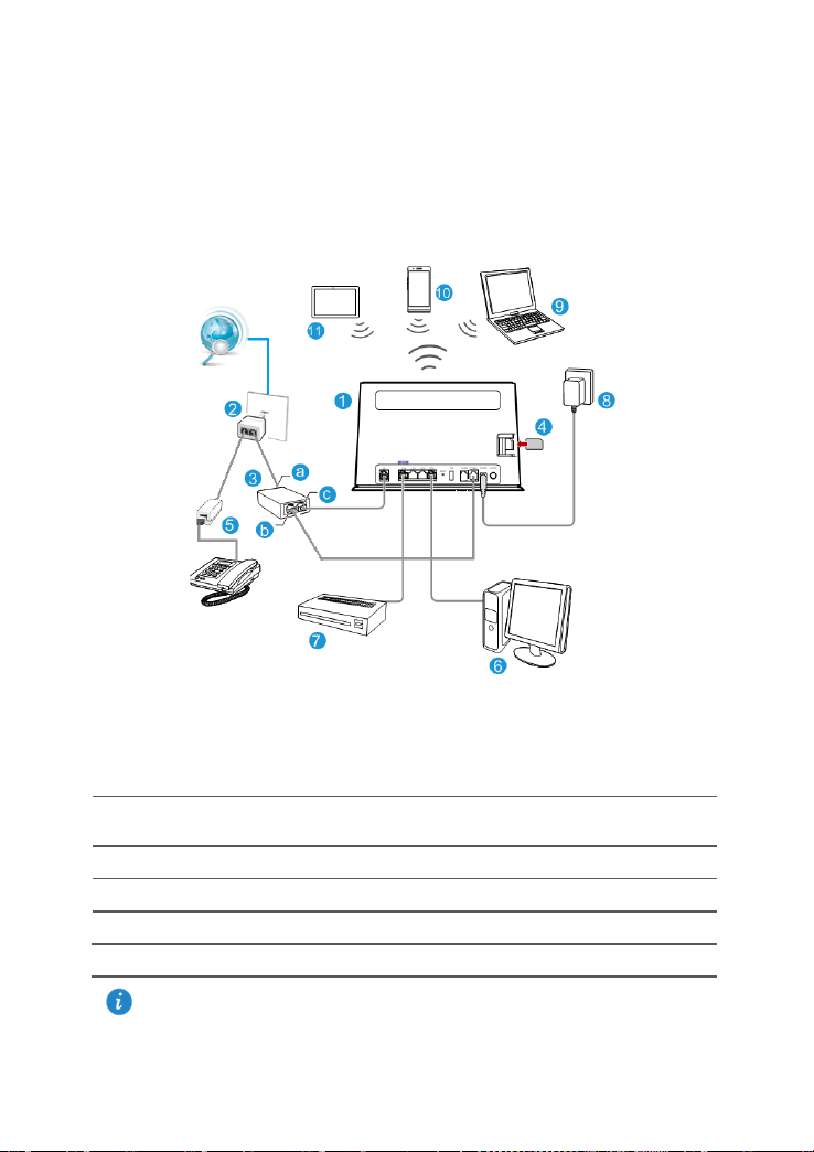
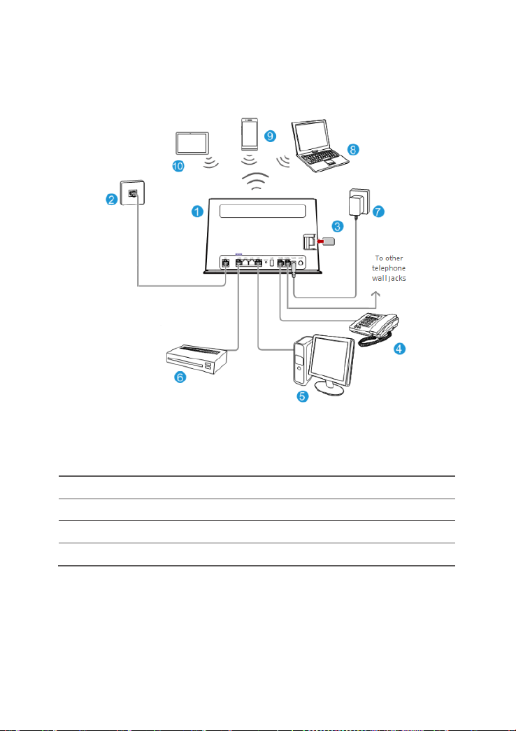
2.2.1. PSTN or Broadband Telephone Line with one voice
channel and a 3G/4G connection
Connect your devices in the sequence indicated in the following figure.
Picture 2-1 connect devices in hybrid broadband network
(PSTN Line)
1 HA35 2 Telephone wall jack &
1 to 2 RJ-11 Y adapter
4 SIM card 5 Telephone & Filter 6 Desktop computer
7 Set-top Box 8 Power adapter 9 Laptop computer
10 Smart Phone 11 Pad
a LINE port b PHONE port c MODEM port
HA35 to a computer.
Version 2.1 (May 2016) 12
3 Splitter
Page 13
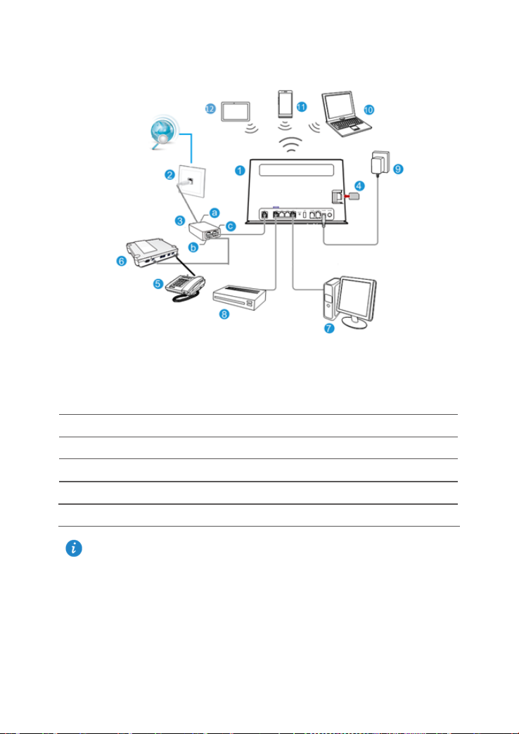
2.2.2. ISDN Line and 3G/4G connection
Connect your devices in the sequence indicated in the following figure.
Picture 2-2 connect devices in hybrid broadband network
(ISDN Line)
1 HA35 2 Telephone wall jack 3 Splitter
4 SIM card 5 Telephone 6 ISDN (NT1) Device
7 Desktop computer 8 Set-top Box 9 Power adapter
10 Laptop computer 11 Smart Phone 12 Pad
a LINE port b PHONE port c MODEM port
When configuring the HA35 for the first time, use an Ethernet cable to connect the HA35
to a computer.
Version 2.1 (May 2016) 13
Page 14
2.2.3. Broadband Telephone Line with the intervention of
an electrician in the internal home wiring (i.e. legacy
ISDN wiring) and a 3G/4G connection
Picture 2-3 connect devices in hybrid broadband network
(intervention of an electrician in the internal home wiring)
1 HA35 2 Telephone wall jack 3 SIM card
4 Telephone 5 Desktop computer 6 Set-top Box
7 Power adapter 8 Laptop computer 9 Smart Phone
10 Pad
Version 2.1 (May 2016) 14
Page 15

2.3. Installing the HA35 on a DSL Broadband Network
2.3.1. PSTN or Broadband Telephone Line with one voice
channel
In some communi ties, Interne t servic e provi ders use tele phone lines to provi de bro adband
access services.
If you have su bscribed to digital subs criber line (DSL) broadb and, you can connect th e
HA35 to a telephone port for Internet access.
Connect your devices in the sequence indicated in the following figure.
Picture 2-4 connect devices in DSL broadband network
(PSTN Line)
1 HA35 2 Telephone wall jack &
1 to 2 RJ-11 Y adapter
4 Telephone & Filter 5 Desktop computer 6 Set-top Box
7 Power adapter 8 Laptop computer 9 Smart Phone
10 Pad
a LINE port b PHONE port c MODEM port
Version 2.1 (May 2016) 15
3 Splitter
Page 16

2.3.2. ISDN Line
Picture 2-5 connect devices in DSL broadband network
(ISDN Line)
1 HA35 2 Telephone wall jack 3 Splitter
4 ISDN (NT1) Device 5 Telephone 6 Desktop computer
7 Set-top Box 8 Power adapter 9 Laptop computer
10 Smart Phone 11 Pad
a LINE port b PHONE port c MODEM port
Version 2.1 (May 2016) 16
Page 17

2.3.3. Broadband Telephone Line with the ntervention of an electrician in the internal home wiring (i.e. legacy ISDN wiring)
Picture 2-6 connect devices in DSL broadband network
(with the intervention of electrician in the internal wiring)
1 HA35 2 Telephone wall jack 3 Telephone
4 Desktop computer 5 Set-top Box 6 Power adapter
7 Laptop computer 8 Smart Phone 9 Pad
Version 2.1 (May 2016) 17
Page 18
3
5
6
4
7
8
1
2
Do not connect the HA35 to the telep hone wal l outlet (or any P ubl i c Switched Telephone
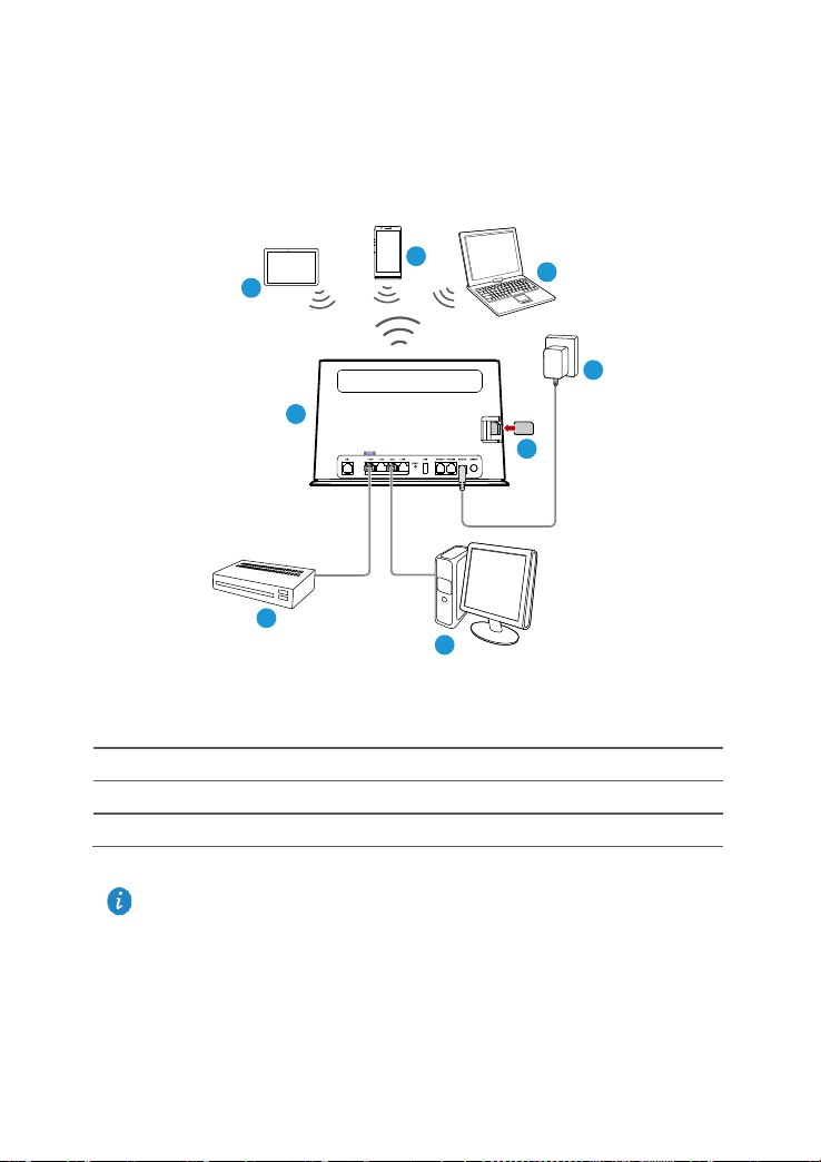
2.4. Installing the HA35 on a 3G/4G Network
If you use the SIM card t o access the Internet, you can insert the SIM car d into the SIM
card slot on the HA35.
Connect your devices in the sequence indicated in the following figure.
Picture 2-7 connect devices in 3G/4G network
1 HA35 2 Desktop computer 3 Set-top Box
4 SIM card 5 Power adapter 6 Laptop computer
7 Smart Phone 8 Pad
Version 2.1 (May 2016) 18
• Insert and remove the SIM card when the HA35 is powered off.
•
Network), because doing so could damage the HA35 due to excessive heat.
Page 19

2.5. Powering On
To power on the HA35, press the POWER button.
After the HA35 is powered on, the POWER indicator turns on. If the indicators do not
behave as expected, ensure that everything is plugged in correctly .
Version 2.1 (May 2016) 19
Page 20
Setting Network Parameters 3.
3.1. Setting the Computer IP Address
Before logging i n to the HA 35 web m anagem ent pag e, se t the IP address of the comp uter
that will be used for the login.
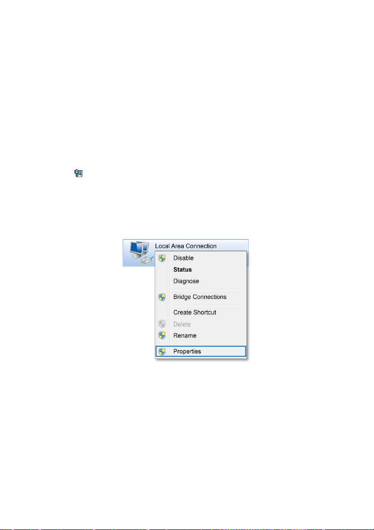
3.1.1. Obtain an IP address automatically
1. Click in the lower right corner of your desktop. Choose Open Network and
Sharing Center .
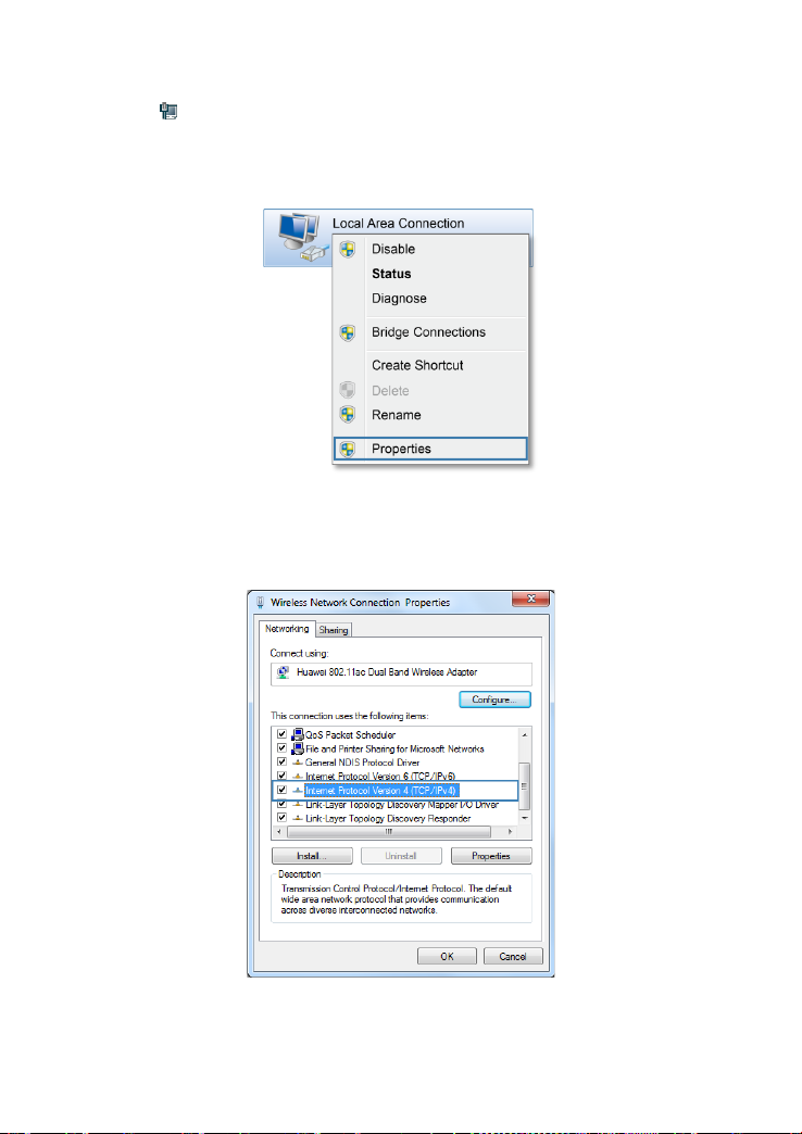
2. Choose Change adapter settings. Right-click Local Area Connection and choose
Properties.
Picture 3-1 local area connection
Version 2.1 (May 2016) 20
Page 21
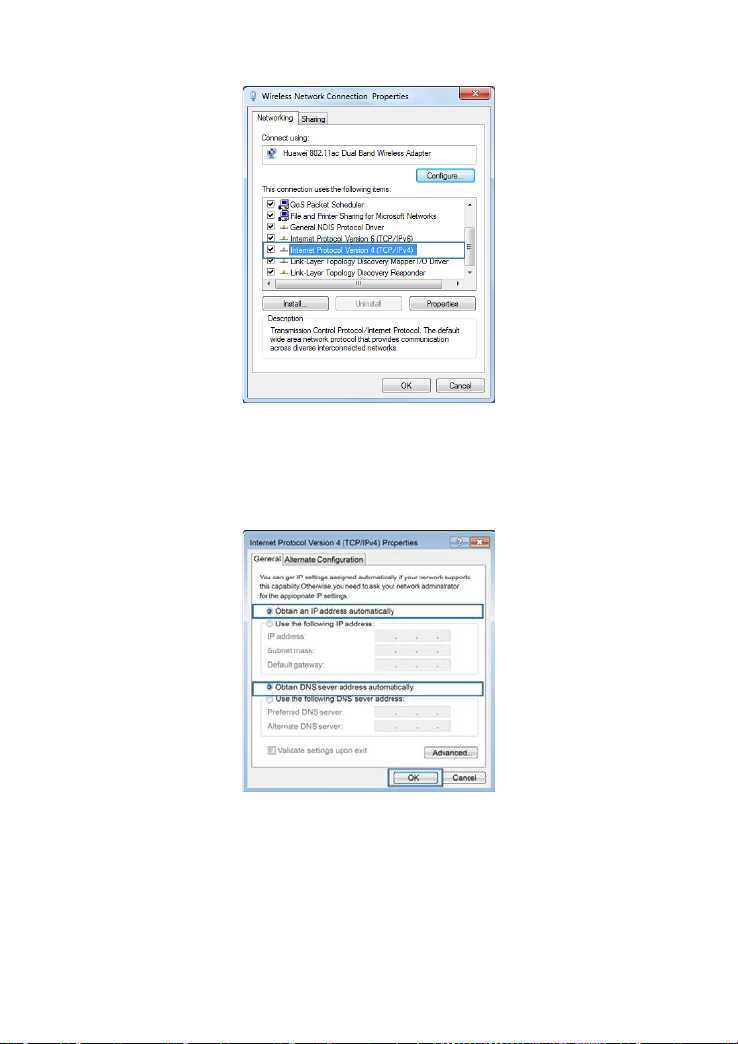
3. Double-click Internet Protocol Version 4 (TCP/IPv4).
Picture 3-2 wireless network connection properties
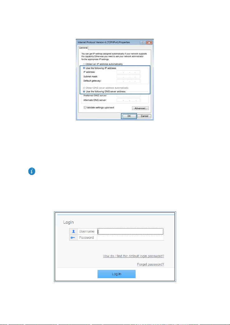
4. Select Obtain an IP address automatically and Obtain DNS server address
automatically. Click OK.
Picture 3-3 internet protocol version 4 properties
Version 2.1 (May 2016) 21
Page 22
3.1.2. Set a static IP address
1. Click in the lower right corner of your desktop. Choose Open Network and
Sharing Center .
2. Choose Change adapter settings. Right-click Local Area Connection and choose
Properties.
Picture 3-4 local area connection
3. Double-click Internet Protocol Version 4 (TCP/IPv4).
Picture 3-5 wireless network connection properties
Version 2.1 (May 2016) 22
Page 23
for the login is connected to the HA35 and has been configured to automatically obtain an
4. Select Use the fol lowing IP addres s. Set IP ad dress to 192.168.1.*, Subnet m ask to
255.255.255.0, and D efaul t gat ewa y to admi. Click OK to return to the previous dialo g
box and click OK.
Picture 3-6 internet protocol version 4 properties
3.2. Logging In to the Web Management Page
The HA35 provides an intuitive web management page where you c an view or set the
HA35 parameters.
Before you log in to the HA35 web management page, ensure that the computer used
IP address or assigned with a static IP address.
1. Open a browser. In the address box, enter 192.168.1.1. Press Enter.
2. Enter the login user name (admin by default) and pass word (the password printed on
the HA35's cover). Click Log in.
Picture 3-7 log in to the Web Management Page
Version 2.1 (May 2016) 23
Page 24

To protect against unauthorized access, change the password after the first login.
where
rrect user name or password three
If you do not perform any operations after logging in to the system for five minutes, you
3. Enter your current password, and a new password. R e-enter the new password to
confirm it, and click Save.
Picture 3-8 account management
•
After modifying the password successfully, this page will jump to the login page,
you can use the new password to log in.
• The system will be locked if you enter inco
consecutive times. One minute later, it will be unlocked.
•
will exit the system and the system automatically returns to the login interface.
3.3. Setting Network Access Parameters
3.3.1. Accessing the Network through the Hybrid gateway
When you install the HA35 for the first time, you need to configure the HA35.
To configure the HA35 through the setup wizard, do as follows:
1. Log in to the web management page.
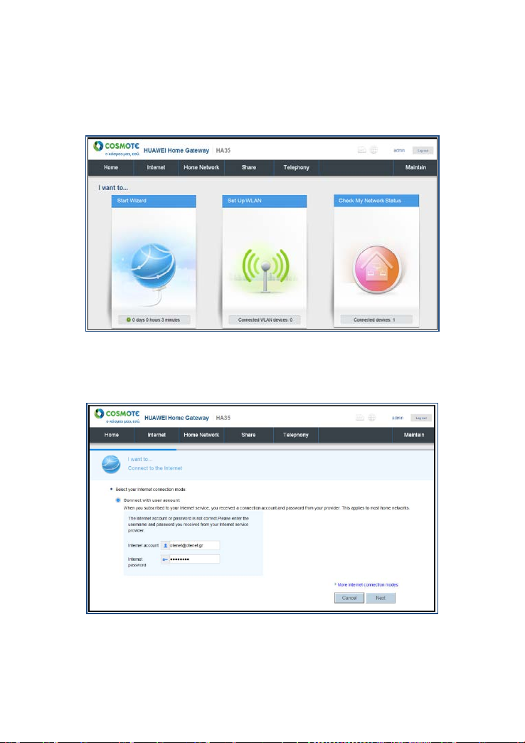
2. Choose Home tab, click Start Wizard.
Picture 3-9 home
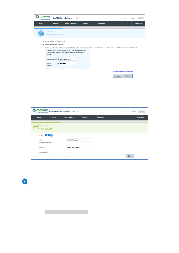
3. Enter the parameters provided by your ISP and click Next
Version 2.1 (May 2016) 24
Page 25
(in the case where the
. Just jump to
Picture 3-10 set internet connection
4. Enter your desired SSID (WLAN name) and key and click Save.
Picture 3-11 set SSID and key
If your SIM card does not need to verify the PIN for I nternet access
customer does not receive any PIN from the operator), ski p step 5 - step 9
step 10.
5. Insert a SIM card into the HA35's SIM card slot.
6. Choose Internet tab, click Internet Settings.The different usa ge sc e na rios will appear,
as shown in Picture 3-12 internet setting s.
Version 2.1 (May 2016) 25
Page 26
Picture 3-12 internet settings
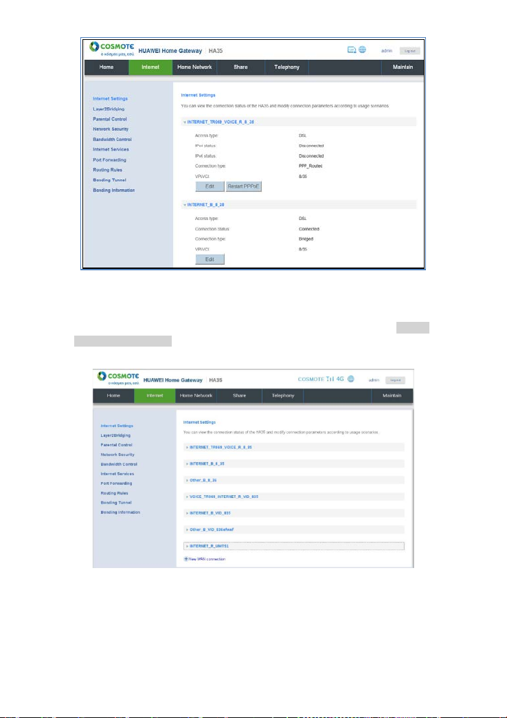
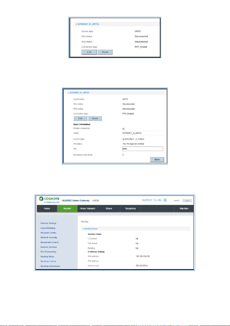
7. Scroll down to find the INTERNET_R_UMTS1 usage scenario, as shown i n Picture
3-13 internet settings 2.
Picture 3-13 internet settings 2
8. Choose INTERNET_R_UMTS1 tab, click Edit.
Version 2.1 (May 2016) 26
Page 27
Picture 3-14 3G/4G vlan
9. Enter the PIN that was provided by your SIM card operator in the PIN text box. Click
Save.
Picture 3-15 set PIN
10. Choose Home tab, click Internet > Bonding Tunnel. If LTE\DSL\Bonding all displayed
UP, it means that your HA35 is working in Hybrid mode.
Picture 3-16 bonding tunnel
Version 2.1 (May 2016) 27
Page 28
3.3.2. Accessing the Network through DSL
When you install the HA35 for the first time, you need to configure the HA35.
To configure the HA35 through the setup wizard, do as follows:
1. Log in to the web management page.
2. Choose Home tab, click Start Wizard.
Picture 3-17 home
3. Enter the parameters provided by your ISP and click Next.
Picture 3-18 set internet connection
4. Enter your desired SSID (WLAN name) and key and click Save
Version 2.1 (May 2016) 28
Page 29

(in
Picture 3-19 set SSID and key
3.3.3. Accessing the Network through the SIM card
Insert the SIM card t o the HA35 so that your device can access the Internet through the
3G/4G uplink service.
If your SIM card does not need to verify the PIN for Internet access, skip this section
the case where the customer does not receive any PIN from the operator).
To set up a dial-up connection for Internet acc ess:
1. Insert a SIM card into the HA35's SIM card slot.
2. Log in to the web management page.
3. Choose Internet tab, click Internet Settings. The different usage scenarios will appear,
as shown in Picture 3-20 internet settings.
Picture 3-20 internet settings
4. Scroll down to find the INTERNET_R_UMTS1 usage scenario, as shown i n Picture
3-21 internet settings 2.
Version 2.1 (May 2016) 29
Page 30

Picture 3-21 internet settings 2
5. Choose INTERNET_R_UMTS1 tab, click Edit.
Picture 3-22 3G/4G vlan
6. Enter the PIN that was p rovided by your S IM card opera tor in the PIN te xt box. Click
Save.
Picture 3-23 set PIN
After you complete the preceding setti ngs, check th e status of the Internet indic ator light.
When the Internet indicator light turns steady green, you can start browsing the Internet.
Version 2.1 (May 2016) 30
Page 31

. To better secure your
3.4. Configuring a Wireless Account
After you Log in to th e web management page, you will see a co nfiguration wizard pa ge
used to configure the wireless account.
1. Log in to the web management page.
2. Choose Home tab, click Set Up WLAN, ent er your desired SSID (W LAN name) and
key and cli ck Save.
Picture 3-24 set SSID and key
To obtain the default SSID and key, check the label on the bottom
WLAN, promptly change the SSID and key.
3.5. Check My Network Status
After you Log in to th e w eb m anag eme nt pa ge, you w ill s ee a page use d to check network
status.
1. Log in to the web management page.
Version 2.1 (May 2016) 31
Page 32

Picture 3-25 home
2. Choose Home ta b, click Che ck My Ne twork Sta tus, and check your network status i n
this page.
Internet icon color The HA35 is connected to the Internet.
gray The HA35 is disconnected from the
Internet.
Device icon (WLAN Device/Ethernet
Device/Phone Device/USB Device)
color The device is connected to the HA35.
gray The device is disconnected from the
HA35.
Table 3-1 connected devices to the HA35 router
Version 2.1 (May 2016) 32
Page 33

Picture 3-26 network status
Wireless Connection Setup 4.
4.1. Setting Up a Wireless Connection Using the
WPS Button
Push the WPS button onc e, t o q uickl y set up a wirel ess c onnecti on betwee n the H A35 a nd
any WPS-capable devic e.
Before you set up a wireless con nection using the WPS button, veri f y the foll o wi ng:
The wireless netwo rk securit y mode of the HA35 is WPA2-PSK or WPA-PSK/WPA2–
PSK.
The wireless device (la ptop, tabl et, or mobi le phone) to connect to the HA35 is W PS-
capable.
1. Press the WPS button on the wir eless devic e to sta rt the WPS negotiati on. For d etails,
see the user guide for the wireless device.
2. Within 2 minutes, press and hold the WPS button on the HA35 for 1 second or more.
When the WP S indicator of the H A35 is on an d then off, a co nnection bet ween the HA35
and wireless device has been set up.
Version 2.1 (May 2016) 33
Page 34

You can also use the tool built into the network adapter to set up a wireless connecti on.
4.2. Manually Setting Up a Wireless Connection
The wireless configuration software provided by Windows is used as an example to
describe how to set up a wireless connection.
For details, see the network adapter's user guide.
Before setting up a wireless connection, record the WLAN name and password of the HA35.
The default WLAN name and password are printed on the HA35 cover label.
4.2.1. On Windows 7
1. Click in the lower right corner of your desk top .
2. From the wireless network list, select the WLAN provided by the HA35. Click Connect.
Picture 4-1 connect Wi-Fi
3. In the displayed dialog box, enter the WLAN password and click OK.
Picture 4-2 Wi-Fi key
4. In the wireless network list, check the WLAN connection status. If the status is
Connected, the computer is wirelessly connected to the HA35.
Picture 4-3 Wi-Fi connected
Version 2.1 (May 2016) 34
Page 35

WLAN Configuration 5.
5.1. Enabling and Disabling the WLAN on the
HA35
The following two methods are available to enable and disable the WLAN on the HA35.
5.1.1. Using the WLAN Button
Press the WLAN butt on in the HA35 to enable or disa ble the W LAN. To ascertain whether
the WLAN is enabled, view the WLAN indicator.
5.1.2. Using the Web Management Page
1. Log in to the web management page.
2. Choose Home Network tab.
3. In the navigation tree, choose WLAN Settings.
Picture 5-1 WLAN basic settings
4. Select Basic Settings configuration page.
5. Set Enable WLAN 2.4 GHz to enabl e.
6. Click Save.
5.2. Changing Your WLAN Name and Password
WLAN access requi res the WLAN na me and password. To improve your WLA N security,
regularly change your WLAN name and password.
1. Log in to the web management page.
2. Choose Home Network tab.
3. In the navigation tree, choose WLAN Settings.
4. Select WLAN Encryption configuration page.
5. In SSID, enter a new WLAN name.
6. In WPA pre-shared key, enter a new WLAN password.
7. Click Save.
Version 2.1 (May 2016) 35
Page 36

Picture 5-2 WLAN Encryption
After the SSID and key had been changed, your computer should use the new ones
to establish a wireless connection to the HA35.
5.3. WLAN Advanced Settings
You can see the Advanced Settings page in WLAN Settings tab, though you can, usually,
keep the default values.
1. Log in to the web management page.
2. Choose Home Network tab.
3. In the navigation tree, choose WLAN Settings (see Picture 5-1 WLAN basic settings).
4. Select Advanced Settings configuration page.
5. Select your desired configuration.
6. Click Save.
Picture 5-3 WLAN Advanced Settings
Version 2.1 (May 2016) 36
Page 37

Network Security 6.
6.1. Improving WLAN Security
6.1.1. Hiding the WLAN Name
After you hide t he WLAN name or SSID, anyone wh o wi she s to connect to th e WLAN must
enter the correct WLAN name. This measure helps improve WLAN security.
1. Log in to the web management page.
2. Choose Home Network tab.
3. In the navigation tree, choose WLAN Settings.
4. Select WLAN Encryption configuration page.
5. Set Enable AP isolation to prevent connections between computers in the same
WLAN network that use the same SSID
6. Set Hide Broadcast to hide the WLAN name. This option also disables WPS.
7. Set Show passw ord to view the password in the WPA pre-shared key text box which
normally is hidden with bull ets
8. Click Save.
Picture 6-1 WLAN Encryption
Version 2.1 (May 2016) 37
Page 38

After the password used for accessing a WLAN is changed, you need to e nter the new
password when connecting a PC to the WLAN.
6.1.2. Using High Security Encryption Modes
Adopting high secu rity encryption mod es protects against un authorized acces s as well as
data interception on networks.
To improve WLAN security without s acrificing working efficiency, use WPA-PSK/WPA2–
PSK and TKIP+AES. This step also prevents W LAN unavailability caused by network
adapters' incompatibility with the selected security mode.
1. Log in to the web management page.
2. Choose Home Network tab.
3. In the navigation tree, choose WLAN Settings.
4. Select WLAN Encryption configuration page.
5. Select the Security mode that you prefer.
6. Select the WPA/WPA2 (strong) or WPA2 (very strong) encryption mode that you
prefer.
7. In WPA pr e-shared key text box, enter the new WLAN password that you want to
specify (see Picture 5-2 WLAN Encryption).
8. Click Save.
Picture 6-2 WLAN Encryption
6.1.3. Enable the WPS Function
After the WP S function is turne d on, you can safel y access the wireless network without
entering a wireless net work name and password.
1. Log in to the web management page.
2. Choose Home Network tab.
3. In the navigation tree, choose WLAN Access (see Picture 5-1 WLAN basic settings).
4. Select the WLAN WPS configuration page.
Version 2.1 (May 2016) 38
Page 39

5. Set Enable WPS to enable.
6. Under the expanded WPS configuration m enu , sel ect th e WPS mode you want to use.
Picture 6-3 WPS by push button
7. WPS by push button (PBC) Enable the WPS function by pressing the WPS button on
the HA35.
8. WPS by client PIN (PIN) Get the pin code from a pin client and then enter it in the PIN
code text box. Click Connect.
Picture 6-4 WPS by client PIN
9. WPS by AP-PIN ( AP -PIN) Click PIN to get the pin code automatically filled-in into the
AP-PIN text box and then enter the same pin code on the pin client e.g. AP (Access
Point).
Version 2.1 (May 2016) 39
Page 40

10. Click Save.
Picture 6-5 WPS by AP-PIN
Version 2.1 (May 2016) 40
Page 41

6.2. Allowing Only Specified Computers to
Access Your WLAN
To prevent unauthori zed acces s to your W LAN, you can specify whic h device s are allowed
to access your WLAN.
1. Connect a computer and the HA35 via wireless.
2. Log in to the web management page.
3. Choose Home Network tab.
4. In the navigation tree, choose WLAN Access (see Picture 5-1 WLAN basic settings).
5. Select WLAN Access Rules configuration page.
6. Set Only allow specific computers in the WLAN to enable the parameter.
7. In Managed LAN devices, click Select all to apply the settings to all connected
devices to the HA35. Or click Add device, to select a specific device.
8. Click Save.
Picture 6-6 WLAN access rules
Picture 6-7 WLAN access rules 2
Version 2.1 (May 2016) 41
Page 42

6.3. Controlling Computer Internet Access
You can prohibit certain PCs from accessing the Internet or allow only certain PCs to
access the Internet. In addition, you can set the period during which the PCs are not
allowed to access the Internet.
1. Log in to the web management page.
2. Choose Internet tab.
3. In the navigation tree, choose Parental Control.
4. Select Time Rules configuration page.
5. Click New time rule parameter.
Picture 6-8 parental control
6. In the Rule n ame text box accordi ng to Picture 6-9 tim e rules below, enter the filtering
rule name that you want.
7. In the Internet access allowed text box, specify the time period that the Parental
Control settings are applied.
Picture 6-9 time rules
Version 2.1 (May 2016) 42
Page 43

8. In Apply to, click Select all to apply the settings to all connected devices to the HA35.
9. Or click Add device, to select a specific device.
Picture 6-10 time rules
10. Click Save.
6.4. Filtering Out Inappropriate Websites
Use URL filtering to prevent certain websites from being accessed.
1. Log in to the web management page.
2. Choose Internet tab.
3. In the navigation tree, choose Parental Control.
4. Select the URL Filter configuration page.
5. Click New URL filter.
Picture 6-11 URL filter
Version 2.1 (May 2016) 43
Page 44

6. In the URL to block text box, enter the Web site address that will be blocked.
7. Click Manually specify devices to enable the parameter.
8. In Ap ply to, click Select all to appl y the settings to all the con nected devices to the
HA35.
Picture 6-12 URL filter
Or click Add device, to s elec t a specif i c devi ce w he re acc es s will be denied to the blocked
Web site address.
Picture 6-13 URL filter – block a device
9. Click Save.
Version 2.1 (May 2016) 44
Page 45

6.5. Configuring the Firewall
The preset protective levels of the firewall are as follows:
Level Description
High
Low
6.5.1. Recommended Firewall Level
To better protect your privacy and prevent the HA35 from malici ous network attacks, it is
recommended that you set the firewall level to High, so that th e LAN compu ters can only
browse the web and downl oad files using an FTP server, while p rohibiting Interne t users
access to the HA35.
6.5.2. Configuring the Firewall
The HA35 provid es a firewall to help secure its WLAN and any devices connected to it. Set
the firewall level based on site requirements to quickly configure the firewall.
1. Log in to the web management page.
2. Choose Internet tab.
3. In the navigation tree, choose Network Security.
4. Select the Firewall configuration pa ge.
5. In Firewall level, select the firewall level that you prefer according to Table 6-1 firewall .
6. Click Save.
When you set the firewall level of the router to High, only the FTP
packets are allowed to pass through.
When you set the firewall level of the router to Low, the active packets
from the LAN to the WAN are allowed to pass through.
Table 6-1 firewall
Version 2.1 (May 2016) 45
Page 46

Picture 6-14 firewall
ICMP Flood: The attacker send s plenty of ICMP packets t o the specific target withi n a
short time period t o request responses, caus ing the target system undul y burdened and
unable to process legitimate transmissions.
SYN Flood: The TCP /IP protocol st ack only pe rmits a limited number of T CP connecti ons
due to resource restricti ons. SYN Flood attacks uti lize this feature. Th e attacker forges a
SYN packet whose s ource address is forged or none xistent, and initia tes a connection t o
the server. Upon receipt of this pac k et, the server replies wit h a SYN-ACK packet . Bec au se
there is no receiver of the SYN-ACK pack et, a half-connection is est ablished. If the attacker
sends large numbers of such packets, a lot of half-connections are established on the
attacked host and the resources of the attacked host are exhausted; therefore, normal
users cannot acc ess the host until th e half-connections expi re. In some implem entations
where connections c an be created withou t restrictions, SYN Floo d has similar influences
that consume the system resources such as the memory.
ARP attack: In ARP attacks, th roug h t he vuln erabi lity of ARP, the attacker makes hos ts o n
a LAN unable to acces s the Internet by forging data to r efresh the dynamic AR P table.
Alternatively, the attacker causes network breakdown or data disclosure by spoofi ng to
steal sensitive information.
6.6. Configure an ACL
After ACL is enabled, you can limit th e access rights of unauthorized users and prevent
network resources from being used improperly.
1. Log in to the web management page.
2. Choose Internet tab.
3. In the navigation tree, choose Network Security.
4. Select the ACL configuration page.
5. Click New ACL.
Version 2.1 (May 2016) 46
Page 47

6. In Service type, select the service type for the access rule that you want to enable.
7. In Access direction, select LAN to apply the ACL to the traffic entering the LAN
interface, or select WAN to apply the ACL to the traffic entering the WAN interface.
8. Click the Choose devices parameter to select the device or devices where the ACL will
be applied.
9. In Block for, click S elec t all to apply the s etti ngs to all connected devices to the H A35.
Or click the device that you want to activate the ACL. Click Add device, to select
another device.
10. Click Save.
Picture 6-15 ACL
Picture 6-16 ACL 2
Version 2.1 (May 2016) 47
Page 48

6.7. Configure DMZ
After DMZ is enabl ed, the computer that i s configured as a D MZ host is exposed to t he
Internet. For exampl e, when building a server, you can c onfigure the compute r providing
external services as a DMZ host, which helps protect other computers on the home
network.
1. Log in to the web management page.
2. Choose Internet tab.
3. In the navigation tree, choose Network Security.
4. Select the DMZ configuration page.
5. In Host address, select the device that you want to act as a DMZ host, or click Add
device to add a new DMZ host.
6. Set Enable DMZ to enable the capability.
7. Click Save.
Picture 6-17 DMZ
6.8. Configure Application Filter
To enable the application filt er function on a s pecified computer, you can block netwo rk
attacks from applications to the specified computer.
1. Log in to the web management page.
2. Choose Internet tab.
3. In the navigation tree, choose Network Security.
4. Select the Application Fil ter c on fi gu ra ti on pa ge.
5. Click New application filter.
Version 2.1 (May 2016) 48
Page 49

Picture 6-18 application filter
6. In Filter name, enter a rule name for the application filter.
7. In Block, select the application you want to filter, or click Add application to add a new
port application.
8. In Block for, click Select all to apply the settings to all conn ected devices to the H A35.
Or click the dev ice that you want to activat e the Applicati on fil ter. Or click Add de vice,
to select a specific device.
9. Click Save.
Picture 6-19 application filter 2
Version 2.1 (May 2016) 49
Page 50

Picture 6-20 application filter 3
6.9. Configure Port Forwarding
You can set forwarding rules on th e H A35 so that users c an easi l y acc ess s erv er r es o ur ces
provided by your computer (such as personal websites and FTP servers) from the Internet.
6.9.1. Configure Port Mapping
By setting a port forwarding rule, you can let an Internet user to access a local computer.
1. Log in to the web management page.
2. Choose Internet tab.
3. In the navigation tree, choose Port Forwarding.
4. Select the Port Mapping c o nfig ur at io n pag e.
5. Click New port mapping.
Version 2.1 (May 2016) 50
Page 51

Picture 6-21 port mapping
6. Picture 6-22 port mapping 2 shows the Mapping name text box, to enter a name for the
port forwarding rule.
7. In Application, sel ect the applicati on type you want to set, or click Add port mappin g
application to add a new application type.
8. In Internal host, select a loc al compu ter yo u want to set , or cli ck Add de vice to add a
new local computer.
9. Click Save.
Picture 6-22 port mapping 2
Version 2.1 (May 2016) 51
Page 52

6.9.2. Configure Port Trigger
By setting port triggering, when the LAN has client-initiated requests from an Internet server,
the application trigg ers a port or ports to initiate a connection, th ereby triggering HA35 to
open the appropriate ports to ensure the normal use of the application.
1. Log in to the web management page.
2. Choose Internet tab.
3. In the navigation tree, choose Port Forwarding.
4. Select the Port Trigger configuration page.
5. Click New port trigger.
Picture 6-23 port trigger
6. Picture 6-24 port trigger 2 shows the Trigger name text box, to enter a name for the
port triggering rule.
7. In Application, select the application type you want to set, or click Add port trigger
application to add a new application type.
8. Click Save.
Picture 6-24 port trigger 2
Version 2.1 (May 2016) 52
Page 53

Internet Services 7.
7.1. Dynamic DNS
The Dynamic Domain Name System (DD NS) dyn amical ly ma ps an IP addres s to a dom ain
name. After DDNS is enabled, the HA35 sends the dynamic IP address of your computer to
the DDNS server. The DD NS serve r then ma ps the upd ated IP address to a fixed domai n
name. Internet users can use the fixed domain name to access resources that your
computer provides, wi tho ut tra c ing the IP addres s of your com pu ter.
1. Log in to the web management page.
2. Choose Internet tab.
3. In the navigation tree, choose Internet Ser vices.
Picture 7-1 dynamic DNS
4. Set Enable DDNS to enable the fea tu r e.
5. Picture 7-2 dynamic DNS 2 shows how to select the supported Provider.
6. Enter the Host name and D om ain name that you have obtained from the domain
name administrative or ganization.
7. Enter the Username and Password that you have registered on the DDNS server.
8. Click Save.
Version 2.1 (May 2016) 53
Page 54

Picture 7-2 dynamic DNS 2
7.2. Simple Network Time Protocol
The Simple Network Time Protocol (SNTP) synchronizes clocks of computers on the
Internet. After SNTP is en abled, the H A35 obtai ns the sta ndard time fr om an Intern et time
server to synchronize to the system time.
1. Log in to the web management page.
2. Choose Internet tab.
3. Picture 7-3 simple network time protocol shows the navigatio n tree to choose Internet
Services.
4. Choose the Primary NTP server and Secondary NTP ser ver .
5. Choose the Local time zone name.
6. Click Save.
Version 2.1 (May 2016) 54
Page 55

Picture 7-3 simple network time protocol
After this function is enabled, the HA35 corrects the system time according to your settings.
7.3. Multicast management
After multicast m anagement is enabled, the HA 35 receives m ulticast data o n the Internet
through the confi gured multicast proxy and forwards multicast data onl y to the terminal
devices that want to receive the multicast data, such as an IPTV STB.
1. Log in to the web management page.
2. Choose Internet tab.
3. Picture 7-4 multicast management shows the navigation tree, to choose Internet
Services.
4. Set Enable IGMP prox y (for IPv4) or Enable MLD proxy (for IPv6) to enable the
feature.
5. Choose the WAN connection.
6. Click Save.
Version 2.1 (May 2016) 55
Page 56

Picture 7-4 multicast management
IP Telephony 8.
8.1. Introduction to IP Telephony
IP telephony, namely voice over Internet Protocol (VoIP), is also called broadband
telephony or Internet telephony. It utilizes Internet Protocol (IP) net work technologies to
implement voice c ommunication. During a VoIP call, voice si gnals are digiti zed, encoded,
packetized, and transmi tted as pack ets over a net work. O n the receivi ng side, the packets
are then decoded, and digital signals are converted to reproduce the original voice streams,
which can be heard b y the cal led pa rty. Different from tradi tion al PS TN call s, VoIP calls are
transported over IP network s, meaning voice streams are tra nsmitted over users' exist ing
broadband Internet. This makes full use of broadband resources.
8.2. Configuring VoIP
The HA35 su pports VoIP. You can place VoIP calls after your phon e is connected to the
Phone port on the HA35.
To use the HA35 to place VoIP calls, ask your network service provider to activate VoIP
services for you. By default, your network service provider will have all related
parameters, such as the VoIP account and address, set for you. You will not need to
configure any settings to place VoIP calls.
Choose Telephony -->VoIP to displ ay the VoIP provider page, as sho wn in Picture 8-1
VoIP providers.
Version 2.1 (May 2016) 56
Page 57

Picture 8-1 VoIP providers
Click on “View” in Picture 8-1 VoIP providers to see the informati on of the VoIP provider as
shown in Picture 8-2 VoIP providers 2. This informati on is filled in automatically by the
system and cannot be changed by the user.
Picture 8-2 VoIP providers 2
To configure voice services, do as follows:
1. Configure a VoIP number.
a. Picture 8-1 VoIP providers shows how to choose Telephony > VoIP > VoIP
Accounts .
b. Click on VoIP Acc ounts to dis play the Vo IP configuratio n page (see Picture 8 -3 VoIP
accounts)
c. Select the VoIP provider name from the drop-down list box.
d. Enter the SIP phone number.
e. Enter the SIP Username and Password.
Version 2.1 (May 2016) 57
Page 58

f. Click Enable to enable the VoIP account.
g. Click Save to save the settings.
Picture 8-3 VoIP accounts
The parameters of th e SIP account , ac cordi ng to Picture 8-3 VoIP accounts, are com plet ed
automatically b y the IMS system in a few minutes after the synchronization of the VoIP
service.
2. Associate your telephone to the VoIP number.
a. Picture 8-1 VoIP p roviders shows how to choose Telephony > Telephone to display
the telephony page (see Picture 8-4 telephon e).
b. Associate your telephone to the VoIP number.
Picture 8-4 telephone
8.3. Placing a VoIP Call
Once your network service provider has activated VoIP services for you, you will be
assigned a VoIP account, which is also your VoIP call number.
Before placing a VoIP call, ensur e that the HA35 has connect ed to the net work. W hen the
call is establish ed, your VoIP call number is displ a yed on the called party's phone.
For VoIP call tariffs, contact your network service provider.
Version 2.1 (May 2016) 58
Page 59

you connect a USB device to t he HA35, verify that the input vol tage and current of t he
USB Device 9.
9.1. USB Storage Device
USB storage devices use their USB ports to exchange data with other devices.
9.2. You can connect a USB storage device to your HA35 and access the USB device from your computer.
Both the USB drive and removable hard disk can connect to your HA35.
Your HA35 supports the following file systems for reading and writing.
FAT32/FAT
NTFS
HFS+
Ext2/3
9.3. Connecting a USB Device
After you connect a U SB device to your HA 35, computers or oth er devices connect ed to
the HA35 network can access and share t he data or applications p rovided by the USB
device.
If
USB device do not exceed 5 V/0.5 A. Otherwise, the HA35 may malfunction.
You can connect the following USB devices to your HA35:
USB storage device
USB printer
9.3.1. Setting the FTP Access Permission
To avoid unauthorized access to the US B storage device, you can set the FTP access
permission on your HA35. This allo ws only authori zed users to access the USB storage
device.
9.3.2. Accessing to FTP Server Through the User Name and
Password
1. Connect the portable storage device to the HA35's USB port.
2. Enable the FTP server.
a. Log in to the web management page.
Version 2.1 (May 2016) 59
Page 60

b. Choose Share > Storage Share.
Picture 9-1 share service settings
c. In Service Settings, select Enable FTP for the FTP server.
d. Click Save to save the settings.
Picture 9-2 share service settings 2
3. Set the user name and password of the portable storage device.
a. Select User Settings configuration page.
b. Click New USB user.
Picture 9-3 share user settings
c. In Username and Password, enter a Username and Password for the FT P server,
and re-enter the Password to confirm it.
d. In Directory mode, choose a file sharing path.
e. In Privilege, select the desired right.
Version 2.1 (May 2016) 60
Page 61

f. Click Save to save the settings.
Picture 9-4 share user settings 2
9.3.3. Accessing a USB Storage Device Using FTP
You can access a USB storage device through the FTP server.
To access a USB storage device using FT P, connect the USB storage devic e to your HA 35
and set the FTP login parameters.
1. Open a browser on your computer.
2. In the address box, enter ftp://192.168.1.1. Press Enter.
3. In the Login dialog box, enter the login user name and password you set in the HA35's
Storage Share page, as shown in Picture 9-1 share service settings and Picture 9-4
share user settings 2 (A nonymous users select the an on ymo us di re ctly).
4. Click Login.
Once you pass the au thentic ation, th e directo ry and file s in the U SB stora ge devic e will be
displayed.
9.3.4. Setting the Samba Access Permission
To prevent unauthorized users f rom accessing data stored in USB devi c es, you can set the
Samba access perm ission fo r the HA 35. Aft er this p ermissi on is set, only au thoriz ed users
can access data stored in USB devices.
1. Connect the portable storage device to the HA35's USB port.
Version 2.1 (May 2016) 61
Page 62

2. Enable the samba server.
a. Log in to the web management page.
b. Choose Share > Storage Share.
c. In Service Settings, select Enable SAMBA for samba server.
d. Click Save to save the settings.
Picture 9-5 FTP service settings
3. Set the user name and password of the portable storage device.
a. Select User Settings configuration page, as shown in Picture 9-6 FTP user settings .
b. Click New USB user.
Picture 9-6 F TP user settings
As shown in Picture 9-7 FT P user settings 2, In Username and Password, enter a user
name and password for the samba server, and re-enter the password to confirm it.
c. In Directory mode, choose a file sharing path that is a directory.
d. In Privilege, select the desired right.
e. Click Save to save the settings.
Version 2.1 (May 2016) 62
Page 63

Picture 9-7 F TP user settings 2
9.3.5. Accessing Data Using Samba
Using Samba, you can securely and easily access data stored in USB devices by
accessing shared network directories.
You have connected a USB device to the HA35 and set its access perm ission.
If the access permission of the USB device is set, your identity will be authenticated. During
the authenticatio n, follo w the o nscreen instructi ons. W hen th e authenti cation i s succes sful,
you will be able to access data stored in the USB device.
9.4. Configuring Multimedia Sharing
You can customize the multimedia share function. For example, you can configure the
HA35 to share only multimedia files in the specified directory.
1. Connect the USB storage device to the HA35's USB port.
2. Log in to the web management page.
3. Choose Share > Multimedia Share.
4. Select Multimedia Sharing conf ig ur ation page.
5. Set Enable DMS to enable.
6. Set Customize sharing directories to enable.
7. Click New directory, select the directory in the USB storage device that you selected.
8. Click Save.
Version 2.1 (May 2016) 63
Page 64

Picture 9-8 multimedia sharing
9.5. Sharing a USB Printer
HA35 supports USB printers. After you con nect a USB printer to your HA35 through the
USB port, you can access the printer from the Internet or internal network.
1. Connect the USB cable of the printer to the USB port on the HA35.
2. Add a Network Printer.
9.5.1. On Windows 7
1. Choose Start > Devices and Printers.
2. Choose Add a printer.
3. Choose Add a network, wireless or Bluetooth printer.
4. Click The printer that I want isn't listed.
5. Choose Select a shared printer by name and enter the printer address in the text box.
myprinter is the customized name of the printer to add. Click Next.
6. Select the model of the printer you want or click Hard Disk to manually install the
printer drive.
7. Click OK.
After you complete the preceding settings, open the files you want to print on your
computer. Then you can choose the printer just installed to print your files.
Version 2.1 (May 2016) 64
Page 65

Maintenance Guide 10.
10.1. Changing the IP Address Used to Log In to
the Web Management Page
The IP address used to log in t o the H A35 we b mana geme nt page is t he HA 35 IP addr ess.
For security or oth er purposes (for ins tance, if the default HA3 5 IP address conflicts with
that of another device on the same network), you can change the HA35 IP address.
1. Log in to the web management page.
2. Choose Home Network tab.
3. In the navigation tree, choose LAN Interface.
4. Select LAN Interface Settings configuration pag e.
5. In IP address, enter a new IP address (Such as: 192.168.1.64).
6. Click Save.
Picture 10-1 change log in IP address
Use the new IP address to log in to the web management page.
10.2. Setting the DHCP Server IP range
The DHCP Server is enabled by defaul t .
1. Log in to the web management page.
2. Choose Home Network tab.
3. In the navigation tree, choose LAN Interface.
4. Select DHCP Server configuration page.
5. Enter the Start IP address and End IP address. (Such as: 2 and 254).
6. Click Save.
Version 2.1 (May 2016) 65
Page 66

Picture 10-2 set the DHCP server IP addresses
10.3. RA Settings
Router Advertis ement (RA) enables a neig hboring compute r to quickly determine w hether
there is an available router.
1. Log in to the web management page.
2. Choose Home Network tab.
3. In the navigation tree, choose LAN Interface.
4. Select RA Settings configuration page.
5. In RA mode, choose Automatic.
6. In ULA mode, choose Disable, because there is no need to use Unique Local
Addersses (ULA), unless it is really needed in your network.
7. Click Save.
Picture 10-3 RA settings
Version 2.1 (May 2016) 66
Page 67

10.4. IPv6 DHCP Server
If your computer supports IPv6, it can be assigned an IPv6 address by the IPv6 DHCP
Server.
1. Log in to the web management page.
2. Choose Home Network tab.
3. In the navigation tree, choose LAN Interface.
4. Select IPv6 DHCP Server configuration page.
5. Set IPv6 DHCP Server to enable.
6. In Configuration mode, choose Auto-configure subnet.
7. Click Save.
Picture 10-4 IPv6 DHCP server
10.5. Changing the Web Management Page
Password
The correct pass word is re quir ed to log in t o the web m ana gemen t pag e. R egular chan ges
to the web manageme nt page password can effectiv ely prevent unauthori zed users from
logging in and modifying important parameters.
1. Log in to the web management page.
2. Choose Maintain tab.
3. In the navigation tree, choose Account Management.
4. Select Modify Login Password configuration page.
5. Click Edit.
6. In Current password, enter the currently used password.
7. In New password, enter a new password.
8. In Confirm password, enter the new password again.
9. Click Save.
Version 2.1 (May 2016) 67
Page 68

button on the rear panel of the HA35 for over 6 seconds. T he user name and
Picture 10-5 m odify log in password
After the password is c ha nged, the login page is dis played. Enter your new pa s swor d t o lo g
in.
If you forget the password, yo u can restore the default settings by pr essing and holding
the Reset
password used for logging in to t he web management page are then restored to their
default values. After the HA35 is restore d to its default setti ngs, all user customized data
will be lost. Perform this operation with caution.
10.6. Rebooting Device
The HA35 supports reboot through the web management page.
To avoid any damage to the HA35, do not power off the HA35 when it is being rebooted.
1. Log in to the web management page.
2. Choose Maintain tab.
3. In the navigation tree, choose Device Managemen t.
4. Select Reboot configuration page.
5. Click Reboot.
6. In the displayed dialog box, click OK.
Picture 10-6 reboot
After the HA35 is rebooted, the login page is displayed. Reenter to log in.
Version 2.1 (May 2016) 68
Page 69

restored to its default settings, change the computer IP address so that it
10.7. Restoring Default Settings
10.7.1. Using the Reset Button
If you forget the login pa ss word to the web man agem ent pag e or c ould not access the web
management page , use the reset b utton on the HA3 5 rear p anel to res tore t he HA3 5 to its
default settings. Perform this operation with caution. After the HA35 is restored to its default
settings, all custom data and sett ings will be lost, and the pass word will be restored to its
default value.
1. Press the HA35 power button to power the HA35 on.
2. Press and hold the reset button for 6 seconds or more.
The HA35 will restart, which will cau se t em po rary network interruptions .
After the HA35 is
is in the same network segment as the 192.168.1.1 default IP address.
10.7.2. Using the Configuration Tool
If the HA35 paramet er settings were configur ed incorre ctly, log in to the web management
page to restore the HA35 t o its defa ult settin gs. Perform this operati on with c aution. After
the HA35 is restor ed to it s de fa ul t se tt i ngs, all c u stom d at a an d se tt in gs wil l b e los t, an d the
password will be restored to it s defa ul t val ue .
1. Log in to the web management page.
2. Choose Maintain tab.
3. In the navigation tree, choose Device Managemen t.
4. Select Factory Restore configuration page.
5. Click Restore.
6. In the displayed dialog box, click OK.
Picture 10-7 restore
10.8. Upgrading Firmware
The HA35 supports firmware upgrades through the web management page. Before
upgrading the fi rmware, pleas e download t he latest firm ware of the HA 35 at the Hua wei's
official website.
To avoid any damage to the HA35, do not power off the HA35 when it is being upgraded.
Version 2.1 (May 2016) 69
Page 70

1. Log in to the web management page.
2. Choose Maintain tab.
3. In the navigation tree, choose Device Managemen t.
4. Select Firmware Update confi gur ation page.
5. Click Browse..., and select the latest firmware you download at the Huawei's official
website.
6. Click Upgrade.
Picture 10-8 firmware update
After the firmware is upgraded, the login page is displayed. Reenter to log in.
10.9. Using Ping Tool Diagnose Network
HA35 supports the Ping functio n. You can check the connec tion between the HA35 and
other hosts (includi ng network equipment) connec tion, such as the connectivit y or delay
between the HA35 and other hosts.
1. Log in to the web management page.
2. Choose Maintain tab.
3. In the navigation tree, choose Tools.
4. Select Ping configuration page.
5. In Target address, enter the IP address or domain name you want to test.
6. Click Detect.
Version 2.1 (May 2016) 70
Page 71

Picture 10-9 ping tool
10.10. Using Tracert Tool Diagnose Network
Tracert function is used to detect the number of other routers that passed when the HA35 is
connected to the test host.
1. Log in to the web management page.
2. Choose Maintain tab.
3. In the navigation tree, choose Tools.
4. Select Traceroute configuration page.
5. In Target address, enter the IP address or domain name you want to test.
6. Click Detect.
Picture 10-10 tracert tool
Version 2.1 (May 2016) 71
Page 72

Reference Operations 11.
11.1. Setting Dial-Up Connection Parameters
When the HA35 work s in Bridge mode you need to perform t his operation. O therwise you
do not need to perform this oper atio n.
Before setting di al-up connection para m eters, verify that the H A3 5 i s c or rectly connected to
your computer and you hav e the dial-u p connec tion accou nt nam e and pas sword pr ovided
by your Internet ser vi ce p rovider (ISP). T hi s sec t io n d em on s tr ates how to set up a Point-toPoint Protocol over Ethernet (PPPoE) connection on Windows.
On Windows 7
1. Choose Start > Control Panel > Network and Internet > Network and Sharing
Center.
Picture 11-1 network and sharing center
2. Under Change your networki ng set ti ngs, click S et u p a new connect io n o r network.
Picture 11-2 change your networking settings
3. In the Set Up a Conne ctio n or Ne two rk wi nd ow, s elect C onne ct t o th e I nter net and
click Next.
Version 2.1 (May 2016) 72
Page 73
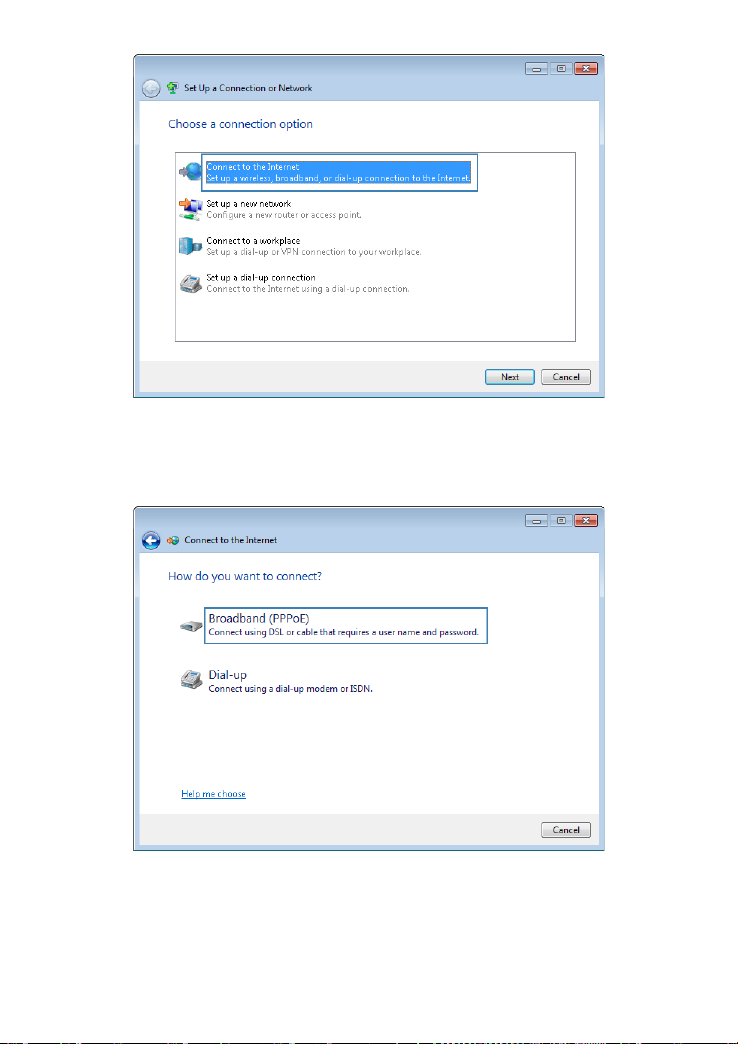
Picture 11-3 set up a conne c tion or network
4. Click Broadband (PPPoE).
Picture 11-4 connect t o inter net
Version 2.1 (May 2016) 73
Page 74

5. In User name and Password, enter the dial-up connection account name and
password provided by your ISP. In Connection nam e, name the dial-u p connection.
Select or deselect Allow other people to use this connection. Then click Connect.
Picture 11-5 connect t o inter net 2
6. Return to the Network and Sharing Center page. Click Change a dapter settings.
Right-click the icon for the dial-up connection you just set up and choose Create
Shortcut from the shortcut menu. In the displayed dialog box, click Yes.
Picture 11-6 create shortcut
After you successfull y set up a PPPoE conn ection, a dial-up c onnection icon is di splayed
on your computer deskto p.
To connect to the Internet, double -click the dial-u p connecti on ico n. In t he displ ayed dial og
box, click Connect.
Version 2.1 (May 2016) 74
Page 75

11.2. Enabling Wireless Configuration on
Windows
If the setup of the wirel ess conn ection bet ween your c omputer a nd the HA 35 failed, verify
that wireless configuration is enabled on Windows.
On Windows 7 or Windows Vista
1. Right-click Computer and choos e Manage from the shortcut menu.
2. In the left panel of the Computer Management window, choose Computer
Management (Local) > Services and Applications > Services.
3. In the right panel of the Computer Management window, right-click WLAN
AutoConfig and choose Properties from the shortcut menu.
4. In the displayed dialog box, check that Service status is Started.
5. Click OK to close the dialog box. Then close the Computer Management window.
11.3. Checking the Computer MAC Address
The MAC address, al so k nown as th e ph ysical a ddress , is a unique i de ntifi er assi gne d to a
network adapter. A MAC address co ntains six groups of two hexadecimal digits, such as
2C-41–38–8D-75–8D. This section demonstrates how to check your computer's MAC
address.
On Windows 7
1. Choose Start > Control Panel > Network and Internet > Network and Sharing
Center > Change adap ter settings. Right-click Local Area Connec tion and choose
Status from the shortcut menu.
Picture 11-7 local area connection
Version 2.1 (May 2016) 75
Page 76

2. Click Details.
Picture 11-8 local area connection details
3. In Network C onnecti on Deta ils, find the line similar to Physical Address 7 0-F3–95–
0C-49–4E. The 70-F3–95–0C-49–4E string is your computer's MAC address.
Picture 11-9 physical address
Version 2.1 (May 2016) 76
Page 77

during thunderstorms, as the signal strength may be unsteady and
FAQs 12.
12.1. What Can I Do If I Cannot Open the Web
Management Page?
1. Open Internet Explorer. Choose Tools > Internet Options > Connections > LAN
settings, and ensure that all check boxes are deselected.
2. Check that the computer IP address is 192.168.1.*. (* is any integer from 64 to 253.)
3. Check that the cables are securely connected to the HA35.
If the problem persists, restore the HA35 to its default settings.
12.2. What Can I Do If the HA35 Cannot Access
the Internet through a Wireless Network
Adapter Sometimes or If the WLAN
Connection Is Unsteady?
This is probabl y bec ause t he HA 35 h as it s cabl es c onnect ed l oosel y, is placed too cl ose to
electronic appliances with intensive interference, or is too far from the computer. Verify that:
1. The power and telephone cables are correctly connected to the HA35.
2. Your computer and the HA35 are far from electric appliances that generate strong
magnetic or electric fields, such as microwave ovens, refrigerators, and cordless
telephones.
3. The HA35 is in an open area, and there are no obstacles, such as concrete or wooden
walls, between the HA35 and the computer.
4. The HA35 is close to the computer.
5. The angle between the HA35 and the computer is appropriate.
Do not use the HA35
the HA35 itself may be damaged due to lightning strikes.
12.3. What Can I Do If I Cannot Access the
Internet?
1. Check that the Power indicator on the HA 35 is steadily on. If the Power indic ator is off ,
perform further checks as follows:
a. Check that the HA35 is turned on.
b. Check that elec tricit y comes f rom the s ocket and t hat th e power i nput from the sock et
meets the requirement s described on the label of the HA 35's power adapter. If the
Version 2.1 (May 2016) 77
Page 78

voltage is unst able, for exampl e, if the v oltage is too high or too l ow, do not us e the
HA35. Wait until the voltage recovers, and then use the HA35.
c. Check that the HA35 is securely connected to the socket using its power adapter.
If the Power indicator is still off, contact an authorized maintenance center.
2. After powering on the HA35 , wait for about 3 m inutes. Then check whether the DSL
indicator turns steadily on.
a. Check that the telephone line is correctly and securely connected, especially the
connection between the telephone line and the splitter.
b. Check that the HA35 and telep hone line are loc ated far from a ny electric ap pliances
that generate strong magnetic or electric fields. Replace the telephone line when
necessary.
If the DSL indicator is still off, contact your network service provider.
3. Check whether the LAN indicator is on. If the LAN indicator is off, perform further
checks as follows:
a. Check that the network adapter on your computer is enabled.
b. Check that the network cable between the HA35 and the computer is securely
connected. Remov e and then insert the net work cable or replace t he network cable
when necessary.
If the LAN indicator is still off, contact an authorized maintenance center.
4. Check that the driver for the network adapter is correctly installed. The following
example uses a comp uter runnin g t he W indows XP oper atin g syst em to ch eck wheth er
the driver for the network adapter is installed:
a. Right-click My Computer, and choose Manage from the displayed shortcut menu.
b. In the Computer Management window, click Device Manager.
c. In the right pane of the Computer Management window, click Networ k ad ap t er s.
If no network adapter is found or if a questio n mark (?) or an exclamatio n mark (!) is
displayed next to the network adapter icon, the driver for the network adapter is not
correctly installed. Re-install the driver.
5. Check that PPP dial-up software is installed and parameters are set correctly. For
details about parameter settings, see the user guide for the PPP dial-up software.
6. Check that you have entered the correct user name and password required by the PPP
dial-up software. T he user name and pass word are provided b y your network servi ce
provider.
7. Check that you can use the P PP dial-up softw are to set up dial -up connection. If the
dial-up connection fails, perform further checks as follows:
a. Close the PPP dial-up softwar e, and power off the HA35. Af ter 5 minutes, power on
the HA35, and use the PPP dial-up software to dial again.
b. Restore the HA35 to its default settings.
If the problem persists, contact your network service provider.
Version 2.1 (May 2016) 78
Page 79

8. Check that the proxy server of the browser is correctly configured. The following
example uses Inte rn et Explorer on t he Windows XP operating system to che ck whether
the proxy server of the browser is correctly configured:
a. Launch Internet Explorer.
b. Choose Tools > Internet Options.
c. In the Internet Options dialog box, click the Connections tab.
d. In the Local Area Network (LAN) settings area, click LAN Settings.
e. In the Proxy server area of the Local Area Netw ork (LAN) Settings dia log box,
check that the Us e a proxy server for your LAN (Th ese settings wi ll not apply to
dial-up or VPN conn ections). check box is cleared.
9. Try to access more websites to check whethe r the HA35 c an acces s these w ebsites. If
the problem persists, contact your network service provider.
12.4. I Often Need to Restart the HA35 to Display
Web Pages. What Can I Do?
Verify the following:
1. Cables are securely connected to HA35 ports. Otherwise, network stability may suffer.
2. Your computer and the HA35 are far from electric appliances that generate strong
magnetic or electric fields, such as microwave ovens, refrigerators, and cordless
telephones.
If the problem persists, contact your Internet Service Provider.
12.5. What Is the Difference Between Wireless
MAC Address Filtering and MAC Address
Filtering?
• Wireless MAC address fi lteri ng: contr ols whethe r a com pute r ca n conn ect to t he HA3 5
over the WLAN.( Please refer to page 41)
• MAC address filtering: controls whether a computer connected to the HA35 can access
the Internet. ( Please refer to page 42)
12.6. Can I Change the WLAN Password?
Yes. To improve your WLAN security, regularly change your WLAN password.
Version 2.1 (May 2016) 79
Page 80

Appendix 13.
13.1. Technical Specifications
Item Specifications
Power supply 12 V DC, 2.5 A
Power consumption < 13 W
Ambient operating
temperature
Ambient humidity 5% to 95% RH (non-condensing)
Dimensions (H x W x D) 160.8 mm x 255.5 mm x 50 mm (6.33 in. x 10.06 in. x
Weight About 512 g
DSL standard ADSL standard
Wireless transmission rate 802.11b Up to 11 Mbit/s
USB type USB 2.0
0°C to 40°C
1.97 in.), antenna excluded
ITU G.992.1(G.dmt)
ITU G.992.3
ITU G.992.5
ADSL2 standard ITU G.992.3
(G.dmt.bis)
ADSL2+ standard ITU G.9 92. 5
(G.dmt.bitplus)
VDSL2 ITU G.993.2 VDSL2
VDSL2 Profiles for 8a,
8b, 8c, 8d, 12a, 12b,
17a
VDSL Vectoring
802.11g Up to 54 Mbit/s
802.11n (2T2R antenna
technology)
Up to 300 Mbit/s
Table 13-1 technical specifications
Version 2.1 (May 2016) 80
Page 81

13.2. Default Settings
Parameter Default Value
LAN port IP address 192.168.1.1
LAN port subnet mask 255.255.255.0
User name to log in to the web
configuration page
Password to log in to the web
configuration page
WLAN name Labeled on the product cover
WLAN password Labeled on the product cover
DHCP Supported
WLAN Supported
Table 13-2 default settings
admin
Labeled on the product cover
Version 2.1 (May 2016) 81
Page 82

For More Help 14.
Please visit http://consumer.huawei.com/en/support/hotline for recently updated h otlin e and
email address in your country or region.
Version 2.1 (May 2016) 82
Page 83

Legal Notice 15.
Copyright © Huawei Technologies Co., Ltd. 2016. All rights reserved.
No part of this m anual may be reproduc ed or transmitted in any form or by any me ans
without prior written consent of Huawei Technologies Co., Ltd. and its affiliates ("Huawei").
The product desc ribed in this manual ma y include cop yrighted software of Huawei and
possible licensors. Customers shall not in any manner reproduce, distribute, modify,
decompile, disas semble, decrypt, extract, reverse engineer, lease, assig n, or sublicense
the said software, unless such restri ctions are prohibit ed by appli cabl e laws or such acti ons
are approved by respective copyright holders.
Trademarks and Permissions
, , and are trademarks or registered trademarks of Huawei
Technologies Co., Ltd.
®
, the Wi-Fi CERTIFIED logo, and the Wi-Fi logo are trademarks of Wi-Fi Alliance.
Wi-Fi
Other trademark s , pr odu ct, service and com p an y n am es m entioned may be the property o f
their respective owners.
Notice
Some features of the product and its accessories descri bed herein rely on the software
installed, capaciti es and settings of loc al network, and therefo re may not be activated o r
may be limited by local network operators or network service providers.
Thus, the descripti ons herein ma y not exactly match th e product or its ac cessories which
you purchase.
Huawei reserves the rig ht to chan ge or mo dify an y informatio n or spec ificatio ns contain ed
in this manual without prior notice and without any liability.
DISCLAIMER
ALL CONTENTS OF THIS MANUAL ARE PROVIDED "AS IS". EXCEPT AS REQUIRED
BY APPLICABLE LAWS, NO WARRANTIES OF ANY KIND, EITHER EXPRESS OR
IMPLIED, INCLUDING BUT NOT LIMITED TO, THE IMPLIED WARRANTIES OF
MERCHANTABILITY AND FITNESS FOR A PARTICULAR PURPOSE, ARE MADE IN
RELATION TO THE ACCURACY, RELIABILITY OR CONTENTS OF THIS MANUAL.
TO THE MAXIMUM EXTENT PERMITTED BY APPLICABLE LAW, IN NO EVENT SHALL
HUAWEI BE LIABLE FOR ANY SPECIAL, INCIDENTAL, INDIRECT, OR
CONSEQUENTIAL DAMAGES, OR LOSS OF PROFITS, BUSINESS, REVENUE, DATA,
GOODWILL SAVINGS OR ANTICIPATED SAVINGS REGARDLESS OF WHETHER SUCH
LOSSES ARE FORSEEABLE OR NOT.
THE MAXIMUM LIABILITY (THIS LIMITATION SHALL NOT APPLY TO LIABILITY FOR
PERSONAL INJURY TO THE EXTENT APPLICABLE LAW PROHIBITS SUCH A
LIMITATION) OF HUAWEI ARISING FROM THE USE OF THE PRODUCT DESCRIBED IN
Version 2.1 (May 2016) 83
Page 84

THIS MANUAL SHALL BE LIMITED TO THE AMOUNT PAID BY CUSTOMERS FOR THE
PURCHASE OF THIS PRODUCT.
Import and Export Regulations
Customers shall c omply with all applicable export or im port laws and regulations and be
responsible to obtain all neces sary governm ental permits a nd licenses i n order to e xport,
re-export or import the product mentioned in this manual including the software and
technical data therein.
Privacy Policy
To better understand how we protect your personal information, ple ase see the privacy
policy at http://consumer.huawei.com/privacy-policy.
Version 2.1 (May 2016) 84
Page 85

Acronyms and Abbreviations 16.
ACL Access Control List
ADSL Asymmetrical Digital Subscriber Line
ADSL2+ Asymmetrical Digital Subscriber Line 2 plus
ARP Address Resolution Protocol
DC Direct Current
DHCP Dynamic Host Configuration Protocol
DMZ Demilitarized Zone
DNS Domain Name System
DSL Digital Subscriber Line
FTP File Transfer Protocol
HTTP Hyper Text Transport Protocol
IEEE Institute of Electrical and Electronics Engineers
ICMP Internet Control Message Protocol
IGMP Internet Group Management Protocol
IP Internet Protocol
LAN Local Area Network
LTE Long Term Evolution
MIMO Multiple-input Multiple-output
MLD Multicast Listener Discovery
PC Personal Com p uter
PIN Personal Identification Number
PPP Point-to-Point Protocol
PSTN Public Switched Telephone Network
PVC Permanent Virtual Circuit
QoS Quality of Service
RA Router Advertisement
SIM Subscriber Identity Module
SIP Session Initiation Protocol
SYN synchronous
TCP Transmission Control Protocol
Version 2.1 (May 2016) 85
Page 86

UMTS Universal Mobile Telecommunicati ons System
URL Uniform Resource Locator
USB Universal Serial Bus
VDSL2 Very High Speed Digital Subscribe Line 2
VoIP Voice over IP
WAN Wide Area Network
WCDMA Wideband Code Division Multiple Access
WLAN Wireless Local Area Network
WPA Wi-Fi Protected Access
WPS Wi-Fi Protected Setup
Version 2.1 (May 2016) 86
Page 87

List of Pictures 17.
Picture 1-1 ports and buttons ..................................................... 7
Picture 1-2 front side .................................................................. 8
Picture 2-1 connect devices in hybrid broadband network
(PSTN Line) ............................................................................. 12
Picture 2-2 connect devices in hybrid broadband network
(ISDN Line) .............................................................................. 13
Picture 2-3 connect devices in hybrid broadband network
(intervention of an electrician in the internal home wiring) ...... 14
Picture 2-4 connect devices in DSL broadband network
(PSTN Line) ............................................................................. 15
Picture 2-5 connect devices in DSL broadband network
(ISDN Line) .............................................................................. 16
Picture 2-6 connect devices in DSL broadband network
(with the intervention of electrician in the internal wiring) ........ 17
Picture 2-7 connect devices in 3G/4G network ....................... 18
Picture 3-1 local area connection ............................................ 20
Picture 3-2 wireless network connection properties ................ 21
Picture 3-3 inter net protoc o l vers ion 4 proper t ies .................... 21
Picture 3-4 local area connection ............................................ 22
Picture 3-5 wireless network connection properties ................ 22
Picture 3-6 inter net protoc o l vers ion 4 proper t ies .................... 23
Picture 3-7 log in to the Web Management Page .................... 23
Picture 3-8 account management ............................................ 24
Picture 3-9 home ..................................................................... 24
Picture 3-10 set internet connection ........................................ 25
Version 2.1 (May 2016) 87
Page 88

Picture 3-11 set SSID and key ................................................. 25
Picture 3-12 internet settings ................................................... 26
Picture 3-13 internet settings 2 ................................................ 26
Picture 3-14 3G/4G vl an .......................................................... 27
Picture 3-15 set PIN ................................................................. 27
Picture 3-16 bonding tunnel ..................................................... 27
Picture 3-17 hom e ................................................................... 28
Picture 3-18 set internet connection ........................................ 28
Picture 3-19 set SSID and key................................................. 29
Picture 3-20 internet settings ................................................... 29
Picture 3-21 internet settings 2 ................................................ 30
Picture 3-22 3G/4G vl an .......................................................... 30
Picture 3-23 set PIN ................................................................. 30
Picture 3-24 set SSID and key................................................. 31
Picture 3-25 hom e ................................................................... 32
Picture 3-26 network status ..................................................... 33
Picture 4-1 connect Wi-Fi ........................................................ 34
Picture 4-2 Wi-Fi key ............................................................... 34
Picture 4-3 Wi-Fi connected .................................................... 34
Picture 5-1 WLAN basic settings ............................................. 35
Picture 5-2 WLAN Encryption .................................................. 36
Picture 5-3 WLAN Advanced Settings ..................................... 36
Picture 6-1 WLAN Encryption .................................................. 37
Picture 6-2 WLAN Encryption .................................................. 38
Picture 6-3 W PS by push button.............................................. 39
Picture 6-4 WPS by client PIN ................................................. 39
Version 2.1 (May 2016) 88
Page 89

Picture 6-5 WPS by AP-PIN ..................................................... 40
Picture 6-6 WLAN access rules ............................................... 41
Picture 6-7 WLAN access rules 2 ............................................ 41
Picture 6-8 parental control ...................................................... 42
Picture 6-9 time rules ............................................................... 42
Picture 6-10 time rules ............................................................. 43
Picture 6-11 URL filter .............................................................. 43
Picture 6-12 URL filter .............................................................. 44
Picture 6-13 URL filter – block a device ................................... 44
Picture 6-14 firewall ................................................................. 46
Picture 6-15 ACL ...................................................................... 47
Picture 6-16 ACL 2 ................................................................... 47
Picture 6-17 DMZ ..................................................................... 48
Picture 6-18 application filter ................................................... 49
Picture 6-19 application filter 2 ................................................ 49
Picture 6-20 application filter 3 ................................................ 50
Picture 6-21 port mapping ....................................................... 51
Picture 6-22 port m appi ng 2 .................................................... 51
Picture 6-23 port trigger ........................................................... 52
Picture 6-24 port trigger 2 ........................................................ 52
Picture 7-1 dynamic DNS ........................................................ 53
Picture 7-2 dynamic DNS 2 ..................................................... 54
Picture 7-3 simple network time protocol ................................. 55
Picture 7-4 multicast management .......................................... 56
Picture 8-1 VoIP providers ....................................................... 57
Picture 8-2 VoIP providers 2 .................................................... 57
Version 2.1 (May 2016) 89
Page 90

Picture 8-3 VoIP accounts ....................................................... 58
Picture 8-4 telephone ............................................................... 58
Picture 9-1 share service settings ........................................... 60
Picture 9-2 share service settings 2 ........................................ 60
Picture 9-3 share user settings ................................................ 60
Picture 9-4 share user settings 2 ............................................. 61
Picture 9-5 FTP service settings .............................................. 62
Picture 9-6 FTP user settings .................................................. 62
Picture 9-7 FTP user settings 2 ............................................... 63
Picture 9-8 multimedia sharing ................................................ 64
Picture 10-1 change log in IP address ..................................... 65
Picture 10-2 set the DHCP server IP addresses ..................... 66
Picture 10-3 RA settings .......................................................... 66
Picture 10-4 IPv6 DHCP server ............................................... 67
Picture 10-5 modify log in pass word ........................................ 68
Picture 10-6 reboot .................................................................. 68
Picture 10-7 restore ................................................................. 69
Picture 10-8 firmware update................................................... 70
Picture 10-9 ping tool ............................................................... 71
Picture 10-10 tracert tool ......................................................... 71
Picture 11-1 network and sharing center ................................. 72
Picture 11-2 change your networking settings ......................... 72
Picture 11-3 set up a connection or network ........................... 73
Picture 11-4 connec t to inte rnet ............................................... 73
Picture 11-5 connect to internet 2 ............................................ 74
Picture 11-6 create shortcut ..................................................... 74
Version 2.1 (May 2016) 90
Page 91

Picture 11-7 local area connection ........................................... 75
Picture 11-8 local area connection details ............................... 76
Picture 11-9 physical address .................................................. 76
Version 2.1 (May 2016) 91
Page 92

List of Tables 18.
Table 1-1 ports and buttons ....................................................... 8
Table 1-2 indicators .................................................................. 10
Table 3-1 connected devices to the HA35 router..................... 32
Table 6-1 firewall ...................................................................... 45
Table 13-1 technical specifications .......................................... 80
Table 13-2 default settings ....................................................... 81
Version 2.1 (May 2016) 92
 Loading...