


Huawei AR532 Router & AR-DCM-Pa
User Manual
Issue
01
Date
2016-09-20
HUAWEI TECHNOLOGIES CO., LTD.

Issue 01 (2016-09-20)
Huawei Proprietary and Confidential
Copyright © Huawei Technologies Co., Ltd.
i
Copyright © Huawei Technologies Co., Ltd. 2016. All rights reserved.
No part of this document may be reproduced or transmitted in any form or by any means without prior
written consent of Huawei Technologies Co., Ltd.
Trademarks and Permissions
and other Huawei trademarks are trademarks of Huawei Technologies Co., Ltd.
All other trademarks and trade names mentioned in this document are the property of their respective
holders.
Notice
The purchased products, services and features are stipulated by the contract made between Huawei and
the customer. All or part of the products, services and features described in this document may not be
within the purchase scope or the usage scope. Unless otherwise specified in the contract, all statements,
information, and recommendations in this document are provided "AS IS" without warranties, guarantees or
representations of any kind, either express or implied.
The information in this document is subject to change without notice. Every effort has been made in the
preparation of this document to ensure accuracy of the contents, but all statements, information, and
recommendations in this document do not constitute a warranty of any kind, express or implied.
Huawei Technologies Co., Ltd.
Address:
Huawei Industrial Base
Bantian, Longgang
Shenzhen 518129
People's Republic of China
Website:
http://www.huawei.com
Email:
support@huawei.com
Huawei AR532 Router & AR-DCM-Pa
User Manual
About This Document
Issue 01 (2016-09-20)
Huawei Proprietary and Confidential
Copyright © Huawei Technologies Co., Ltd.
ii
Intended Audience
Symbol
Description
Indicates an imminently hazardous situation
which, if not avoided, will result in death or
serious injury.
This document describes the AR532 hardware structure and provides installation instructions,
covering the equipment appearance and specifications, installation preparations, equipment
installation procedure, and cable connection.
This document is intended for:
Hardware installation engineers
Onsite maintenance engineers
About This Document
Symbol Conventions
The symbols that may be found in this document are defined as follows.
Huawei AR532 Router & AR-DCM-Pa
User Manual
About This Document
Issue 01 (2016-09-20)
Huawei Proprietary and Confidential
Copyright © Huawei Technologies Co., Ltd.
iii
Symbol
Description
Indicates a potentially hazardous situation
which, if not avoided, could result in death
or serious injury.
Indicates a potentially hazardous situation
which, if not avoided, may result in minor
or moderate injury.
Huawei AR532 Router & AR-DCM-Pa
User Manual
About This Document
Issue 01 (2016-09-20)
Huawei Proprietary and Confidential
Copyright © Huawei Technologies Co., Ltd.
iv
Symbol
Description
Indicates a potentially hazardous situation
which, if not avoided, could result in
equipment damage, data loss, performance
deterioration, or unanticipated results.
NOTICE is used to address practices not
related to personal injury.
Calls attention to important information,
best practices and tips.
NOTE is used to address information not
related to personal injury, equipment
damage, and environment deterioration.
Change History
Changes between document issues are cumulative. The latest document issue contains all the
changes made in earlier issues.
Issue 01 (2016-09-20)
This issue is the first official release.

Huawei AR532 Router & AR-DCM-Pa
User Manual
Contents
Issue 01 (2016-09-20)
Huawei Proprietary and Confidential
Copyright © Huawei Technologies Co., Ltd.
v
Contents
About This Document .................................................................................................................... ii
1 Hardware Description .................................................................................................................. 1
1.1 Chassis .......................................................................................................................................................................... 1
1.1.1 Version Mapping ........................................................................................................................................................ 1
1.1.2 Appearance ................................................................................................................................................................ 1
1.1.3 Indicator Description ................................................................................................................................................. 3
1.1.4 Interface Description.................................................................................................................................................. 5
1.1.5 Technical Specifications ............................................................................................................................................ 7
1.2 Modules ........................................................................................................................................................................ 8
1.2.1 PLC Module............................................................................................................................................................... 8
2 Hardware Installation ................................................................................................................ 11
2.1 Preparations ................................................................................................................................................................ 11
2.1.1 Safety Precautions ................................................................................................................................................... 11
2.1.2 Checking the Installation Environment ................................................................................................................... 12
2.1.3 Preparing Installation Tools ..................................................................................................................................... 13
2.2 Installing an AR532 Router ........................................................................................................................................ 14
2.2.1 Installing the Router in a Three-Meter Box ............................................................................................................. 14
2.2.2 (Optional) Installing a PLC Module in the Router................................................................................................... 17
Huawei AR532 Router & AR-DCM-Pa
User Manual
1 Hardware Description
Issue 01 (2016-09-20)
Huawei Proprietary and Confidential
Copyright © Huawei Technologies Co., Ltd.
1
About This Chapter
Router Model
Software Version
AR532
V200R008C20 and later versions
1.1 Chassis
1.2 Modules
1.3 Cables
1 Hardware Description
1.1 Chassis
1.1.1 Version Mapping
Table 1-1 lists the mapping between the AR532 router and software versions.
Table 1-1 Mapping between the AR532 router and software versions
1.1.2 Appearance
Figure 1-1 shows the appearance of the AR532 router.
Huawei AR532 Router & AR-DCM-Pa
User Manual
1 Hardware Description
Issue 01 (2016-09-20)
Huawei Proprietary and Confidential
Copyright © Huawei Technologies Co., Ltd.
2
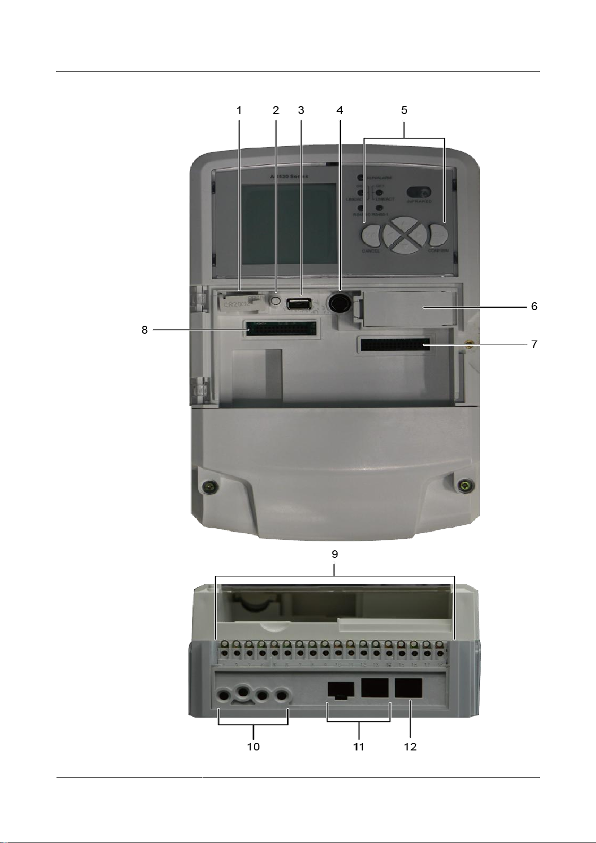
Figure 1-1 AR532 appearance

Huawei AR532 Router & AR-DCM-Pa
User Manual
1 Hardware Description
Issue 01 (2016-09-20)
Huawei Proprietary and Confidential
Copyright © Huawei Technologies Co., Ltd.
3
1
Coin battery holder
NOTE
To prevent short circuiting of the coin
battery, use insulated tweezers to replace
the battery.
2
Cover open sensor
3
USB interface
4
PS/2 (RS232 interface)
5
Operation keys
6
Backup battery holder
NOTE
To ensure optimal performance of the
battery, it is recommended that the battery
be used within a temperature range of
-10°C to +60°C (14°F to 140°F).
7
3G module slot
8
PLC/RF module slot
9
Auxiliary terminals
NOTE
Terminals 15 to 18 (A1, B1, A2, B2) are
used for RS485 interfaces.
10
AC power socket
11
GE combo interface
12
GE electrical interface
Related Documents
Video: (video)Huawei AR532 Introduction
1.1.3 Indicator Description
Figure 1-2 shows indicators on the AR532 router.

Huawei AR532 Router & AR-DCM-Pa
User Manual
1 Hardware Description
Issue 01 (2016-09-20)
Huawei Proprietary and Confidential
Copyright © Huawei Technologies Co., Ltd.
4
Figure 1-2 Indicators on the AR532
Numbe
r
Indicator
Color
Description
1
RUN/ALM
Red and
green
Slow blinking green: The system is running
properly.
Fast blinking green: The system is powering on
or is restarting.

Huawei AR532 Router & AR-DCM-Pa
User Manual
1 Hardware Description
Issue 01 (2016-09-20)
Huawei Proprietary and Confidential
Copyright © Huawei Technologies Co., Ltd.
5
Numbe
r
Indicator
Color
Description
Steady red: A fault that affects services has
occurred. The fault cannot be rectified
automatically and requires manual intervention.
Off: The system software is not running or is
resetting.
2/4
GE electrical
interface
indicators
(GE0 and
GE1)
Green
Steady on: A link has been established on the
corresponding GE electrical interface.
Blinking: Data is being transmitted or received
on the corresponding GE electrical interface.
Off: No link is established on the corresponding
GE electrical interface.
3/5
RS485
interface
indicators
(RS4850 and
RS4851)
Orange
Steady on: The corresponding RS485 link is
available, but the interface is not connected or is
not transmitting or receiving data.
Fast blinking: The corresponding RS485 link is
available and is transmitting or receiving data.
Off: The corresponding RS485 link is not
configured or has failed.
Attribute
Description
Connector type
TYPE-A
Standards compliance
USB 2.0
Working mode
Host
1.1.4 Interface Description
USB Interface
Do not remove the USB flash drive during a USB-based deployment. Otherwise, the system
will restart.
The USB interface supports USB 2.0 devices and provides upload and download speeds of
480 Mbit/s. You can use the USB interface to upload or download configuration and
application files to the flash memory. Table 1-2 lists USB interface attributes.
Table 1-2 USB interface attributes

Huawei AR532 Router & AR-DCM-Pa
User Manual
1 Hardware Description
Issue 01 (2016-09-20)
Huawei Proprietary and Confidential
Copyright © Huawei Technologies Co., Ltd.
6
GE Electrical Interface
Attribute
Description
Connector type
RJ45
Standards compliance
IEEE802.3, IEEE802.3u, IEEE802.3ab
Interface attribute
MDI/MDIX
NOTE
MDI stands for medium dependent interface,
an Ethernet interface connection mode.
Ethernet interfaces of most network interface
cards (NICs) are MDI interfaces.
MDIX stands for medium dependent
interface crossover, a version of MDI. MDIX
interfaces are usually used on HUB or LAN
switch.
Frame format
Ethernet_II, Ethernet_SAP, Ethernet_SNAP
Network protocol
IP
Cable type
Ethernet Cable
Attribute
Description
Connector type
SMA
Standards compliance
3GPP TS 134 121-1
Frequency bands supported
UMTS: 2100/900 (MHz)
EDGE/GPRS/GSM: 1900/1800/900/850
(MHz)
Rate
GSM CS:
Uplink: 9.6 kbit/s
Downlink: 9.6 kbit/s
GPRS/EDGE: Multi-slot Class 12, Class B
WCDMA CS:
A GE electrical interface (10/100/1000 Mbit/s auto-sensing) transmits and receives Ethernet
services at 10 Mbit/s, 100 Mbit/s, or 1000 Mbit/s. Table 1-3 lists GE electrical interface
attributes.
Table 1-3 GE electrical interface attributes
3G-WCDMA Antenna Interface
The 3G-WCDMA antenna interface connects to a 3G-WCDMA antenna to receive and
transmit 3G signals. Table 1-4 lists 3G-WCDMA antenna interface attributes.
Table 1-4 3G-WCDMA antenna interface attributes

Huawei AR532 Router & AR-DCM-Pa
User Manual
1 Hardware Description
Issue 01 (2016-09-20)
Huawei Proprietary and Confidential
Copyright © Huawei Technologies Co., Ltd.
7
Attribute
Description
Uplink: 64 kbit/s
Downlink: 64 kbit/s
WCDMA PS:
Uplink: 384 kbit/s
Downlink: 384 kbit/s
HSDPA: downlink rate of 3.6 Mbit/s
Network protocol
GSM/GPRS/EDGE/WCDMA/HSDPA
Antenna type
3G Whip Antenna
Item
Description
System parameters
Processor
Dual-core, 700 MHz
Memory
256 MB
Flash memory
512 MB
Dimensions and weight
Dimensions (W x
D x H)
290 mm x 180 mm x 95 mm (11.42 in. x 7.09 in. x 3.74 in.)
Weight
2.5 kg (5.51 lb)
Power specifications
Rated input voltage
Single-phase: 100 V to 240 V AC
GE Combo Interface
A GE combo interface consists of an optical Ethernet interface and an electrical Ethernet
interface on the panel. The two interfaces have only one internal forwarding interface. The
electrical and optical interfaces are multiplexed, and only one of them can work at a time.
When one of the Ethernet interfaces is working, the other interface is shut down.
A GE electrical interface (10/100/1000 Mbit/s auto-sensing) transmits and receives
services at 10 Mbit/s, 100 Mbit/s, or 1000 Mbit/s.
The GE optical interface (100/1000 Mbit/s auto-sensing) transmits and receives services
at 100 Mbit/s or 1000 Mbit/s.
By default, a combo interface works as an electrical interface and uses an Ethernet cable to transmit and
receive data.
1.1.5 Technical Specifications
Table 1-5 lists the technical specifications of the AR532 router.
Table 1-5 AR532 technical specifications

Huawei AR532 Router & AR-DCM-Pa
User Manual
1 Hardware Description
Issue 01 (2016-09-20)
Huawei Proprietary and Confidential
Copyright © Huawei Technologies Co., Ltd.
8
Item
Description
range Three-phase: 173 V to 415 V AC
Maximum input
voltage range
Single-phase: 90 V to 290 V AC
Three-phase: 304 V to 456 V AC
Power consumption
Maximum power
consumption
12.5 W
Environment parameters
Operating
environment
temperature
-25°C to +70°C (-13°F to +158°F)
NOTE
The operating temperature cannot exceed 65°C (149°F) when a 3G module is
used in the router.
Storage
temperature
-40°C to +85°C (-40°F to +185°F)
Operating relative
humidity
5% to 95%, noncondensing
Operating altitude
< 5000 m (16404 ft.)
1.2 Modules
1.2.1 PLC Module
Appearance
Figure 1-3 shows the appearance of a PLC module.
Figure 1-3 PLC module appearance

Huawei AR532 Router & AR-DCM-Pa
User Manual
1 Hardware Description
Issue 01 (2016-09-20)
Huawei Proprietary and Confidential
Copyright © Huawei Technologies Co., Ltd.
9
Panel
Number
Item
Color
Description
1
PWR
indicator
Green
Steady on: The system power supply is normal.
Off: The system power is off.
2
TX
indicator
Green
Startup stage: blinks at variable frequencies.
Operation stage: shows the currently working
frequency band and serial number identifier
(SNID) of the PLC module in the same way.
Show the SNID: The indicator keeps on for
500 ms and then off for 500 ms. The number
of alternations between the on and off states
depends on the SNID value.
After showing the SNID, the indicator stays
off for 5s.
Show the working frequency band: The
indicator keeps on for 2s and then off for 2s.
This process lasts for 4s to 16s, depending on
the frequency band used.
− Band 0: The indicator turns on once.
− Band 1: The indicator turns on twice.
− Band 2: The indicator turns on three times.
− Band 3: The indicator turns on four times.
After showing the working frequency band,
the indicator stays off for 5s, and then starts to
Figure 1-4 shows the panel of a PLC module.
Figure 1-4 Panel of a PLC module

Huawei AR532 Router & AR-DCM-Pa
User Manual
1 Hardware Description
Issue 01 (2016-09-20)
Huawei Proprietary and Confidential
Copyright © Huawei Technologies Co., Ltd.
10
Number
Item
Color
Description
show the SNID again.
3
RX
Green
Startup stage: blinks at variable frequencies.
Operation stage: steady on when data is being
received and off when no data is received.
Part Number
Module Name
Description
50030153
AR-DCM-Pa
PLC module
Ordering Information
To place an order, contact the Huawei local office.
Table 1-6 provides the ordering information.
Table 1-6 Ordering information

Huawei AR532 Router & AR-DCM-Pa
User Manual
2 Hardware Installation
Issue 01 (2016-09-20)
Huawei Proprietary and Confidential
Copyright © Huawei Technologies Co., Ltd.
11
About This Chapter
2.1 Preparations
2.2 Installing an AR532 Router
2 Hardware Installation
2.1 Preparations
2.1.1 Safety Precautions
Before you start the installation procedure, read all safety precautions described in this
document and observe any warning labels affixed to the equipment. Doing so will ensure your
safety and protect the equipment from damage.
Safety precautions provided in this document may not cover every eventuality, so remain
mindful of safety at all times.
Only trained and qualified personnel should be allowed to install, operate or maintain the
equipment.
General Safety Guidelines
Always take precautions against ESD whenever you handle the equipment. For example,
wear ESD gloves or an ESD wrist strap. To avoid electric shock or burn, remove
conductive objects like jewelry and watch.
After installing the equipment in a cabinet or rack, connect a ground cable to the
equipment. The ground cable must be connected first and disconnected last.
Environmental Safety

Huawei AR532 Router & AR-DCM-Pa
User Manual
2 Hardware Installation
Issue 01 (2016-09-20)
Huawei Proprietary and Confidential
Copyright © Huawei Technologies Co., Ltd.
12
Do not install the equipment in an environment with flammable or explosive gases or smoke.
Item
Requirement
Heat dissipation
There must be more than 50 mm clearance around the
equipment for heat dissipation.
Cleanness
The equipment must be installed in a clean, dry, well
ventilated site.
Electrical Safety
Install the equipment in a dry environment away from sources of water.
The installation site must be well ventilated to ensure normal operation of the equipment.
Contact with high-voltage power can be fatal. Misoperations on high-voltage facilities
may result in fire, electric shock, or other accidents.
Never install or remove the equipment and power cables while the power is on. The
electric arc or spark generated between a power cable and conductor may cause fire or eye
damage.
To protect personal and equipment safety, ground the equipment before connecting it to a
power source.
Mechanical Safety
Protect the equipment from collision during transportation and unpacking.
If damage is found on the shell of the equipment, which may be caused by collision during
movement or installation, contact the equipment supplier immediately. Do not power on
the equipment in this case.
Place the equipment on a shelf in your warehouse. Do not stack more than 10 boxes of
routers or more than 10 unpacked routers together.
2.1.2 Checking the Installation Environment
Before the installation, ensure that the environment in the installation site meets operation
requirements of the equipment.
The following table lists requirements for the installation environment.

Huawei AR532 Router & AR-DCM-Pa
User Manual
2 Hardware Installation
Issue 01 (2016-09-20)
Huawei Proprietary and Confidential
Copyright © Huawei Technologies Co., Ltd.
13
Item
Requirement
The installation site must be free from leaking or
dripping water, heavy dew, and humidity.
Temperature and humidity
Operating temperature: -25°C to +70°C (-13°F to
+158°F)
Operating relative humidity: 5% to 95%
(noncondensing)
NOTE
If the relative humidity exceeds 70%, use dehumidifiers or
dehumidifying air conditioners.
Corrosive gases avoidance
There must be no acidic, alkaline, or other corrosive gases
in the installation site.
Surge protection
Deploy signal cables on internal walls. Do not route
cables aerially in outdoor environments.
Keep signal cables away from power cables and surge
protection devices.
Electromagnetic
environment
See Electromagnetism Requirements for the Equipment
Room.
Tool
Function
Picture
Flat-head
screwdriver
Used to turn
slotted-head screws
and bolts.
Phillips
screwdriver
Used to turn
cross-head screws and
bolts.
Marker
Used to draw lines
and mark labels.
Diagonal
pliers
Used to cut insulation
tubes and cable ties.
2.1.3 Preparing Installation Tools
The following table lists the tools used for the installation.

Huawei AR532 Router & AR-DCM-Pa
User Manual
2 Hardware Installation
Issue 01 (2016-09-20)
Huawei Proprietary and Confidential
Copyright © Huawei Technologies Co., Ltd.
14
2.2 Installing an AR532 Router
2.2.1 Installing the Router in a Three-Meter Box
Tools and Accessories
Three-meter box (purchased separately)
Three-phase four-pin power cable
M4 screws (two)
Flat-head screwdriver
Phillips screwdriver
The three-phase four-pin power cable and M4 screws are included in the accessory package of the
three-meter box.
Procedure
Step 1 Use a Phillips screwdriver to loosen the screws at two sides of the lower protection cover on
the AR532 router, and then remove the cover.

Huawei AR532 Router & AR-DCM-Pa
User Manual
2 Hardware Installation
Issue 01 (2016-09-20)
Huawei Proprietary and Confidential
Copyright © Huawei Technologies Co., Ltd.
15
Step 2 Hang the AR532 router on the screw in the meter box by the mounting hole at the back of the
router, and use two M4 screws to secure the router in the meter box.
Step 3 Remove power cable cover and connect the three-phase four-pin power cable to the AR532
router and circuit breaker.
The power terminals on the AR532 router are La, Lb, Lc, and N from left to right.

Huawei AR532 Router & AR-DCM-Pa
User Manual
2 Hardware Installation
Issue 01 (2016-09-20)
Huawei Proprietary and Confidential
Copyright © Huawei Technologies Co., Ltd.
16
Step 4 Install the power cable cover, and then the lower protection cover to the AR532 router.

Huawei AR532 Router & AR-DCM-Pa
User Manual
2 Hardware Installation
Issue 01 (2016-09-20)
Huawei Proprietary and Confidential
Copyright © Huawei Technologies Co., Ltd.
17
----End
2.2.2 (Optional) Installing a PLC Module in the Router
Tools and Accessories
PLC module (purchased separately)
Phillips screwdriver
Procedure
Step 1 Use a Phillips screwdriver to loosen the screw at the right side of the upper protection cover
on the AR532 router, open the upper protection cover, and install the PLC module into the
router.

Huawei AR532 Router & AR-DCM-Pa
User Manual
2 Hardware Installation
Issue 01 (2016-09-20)
Huawei Proprietary and Confidential
Copyright © Huawei Technologies Co., Ltd.
18
Step 2 Close the upper protection cover, install the lower protection cover, and tighten screws on
them.

Huawei AR532 Router & AR-DCM-Pa
User Manual
2 Hardware Installation
Issue 01 (2016-09-20)
Huawei Proprietary and Confidential
Copyright © Huawei Technologies Co., Ltd.
19
-
This device complies with part 15 of the FCC Rules. Operation is subject to the following two
conditions: (1) This device may not cause harmful interference, and (2) this device must
accept any interference received, including interference that may cause undesired operation.
Changes or modifications not expressly approved by the party responsible for compliance
could void the user's authority to operate the
equipment.
---End
 Loading...