


Huawei AP8030DN & AP8130DN
Hardware Installation and
Maintenance Guide
Issue
Date 2015-05-18
HUAWEI TECHNOLOGIES CO., LTD.
03

Copyright © Huawei Technologies Co., Ltd. 2015. All rights reserved.
No part of this document may be reproduced or transmitted in any form or by any means without prior written
consent of Huawei Technologies Co., Ltd.
Trademarks and Permissions
and other Huawei trademarks are trademarks of Huawei Technologies Co., Ltd.
All other trademarks and trade names mentioned in this document are the property of their respective holders.
Notice
The purchased products, services and features are stipulated by the contract made between Huawei and the
customer. All or part of the products, services and features described in this document may not be within the
purchase scope or the usage scope. Unless otherwise specified in the contract, all statements, information,
and recommendations in this document are provided "AS IS" without warranties, guarantees or representations
of any kind, either express or implied.
The information in this document is subject to change without notice. Every effort has been made in the
preparation of this document to ensure accuracy of the contents, but all statements, information, and
recommendations in this document do not constitute a warranty of any kind, express or implied.
Huawei Technologies Co., Ltd.
Address: Huawei Industrial Base
Bantian, Longgang
Shenzhen 518129
People's Republic of China
Website: http://enterprise.huawei.com
Issue 03 (2015-05-18) Huawei Proprietary and Confidential
Copyright © Huawei Technologies Co., Ltd.
i
Huawei AP8030DN & AP8130DN
Hardware Installation and Maintenance Guide About This Document
About This Document
Intended Audience
This document describes hardware features of the AP8030DN and AP8130DN and provides
basic installation methods.
This document is intended for:
l Network planning engineers
l Hardware installation engineers
l Commissioning engineers
l Onsite maintenance engineers
l System maintenance engineers
Symbol Conventions
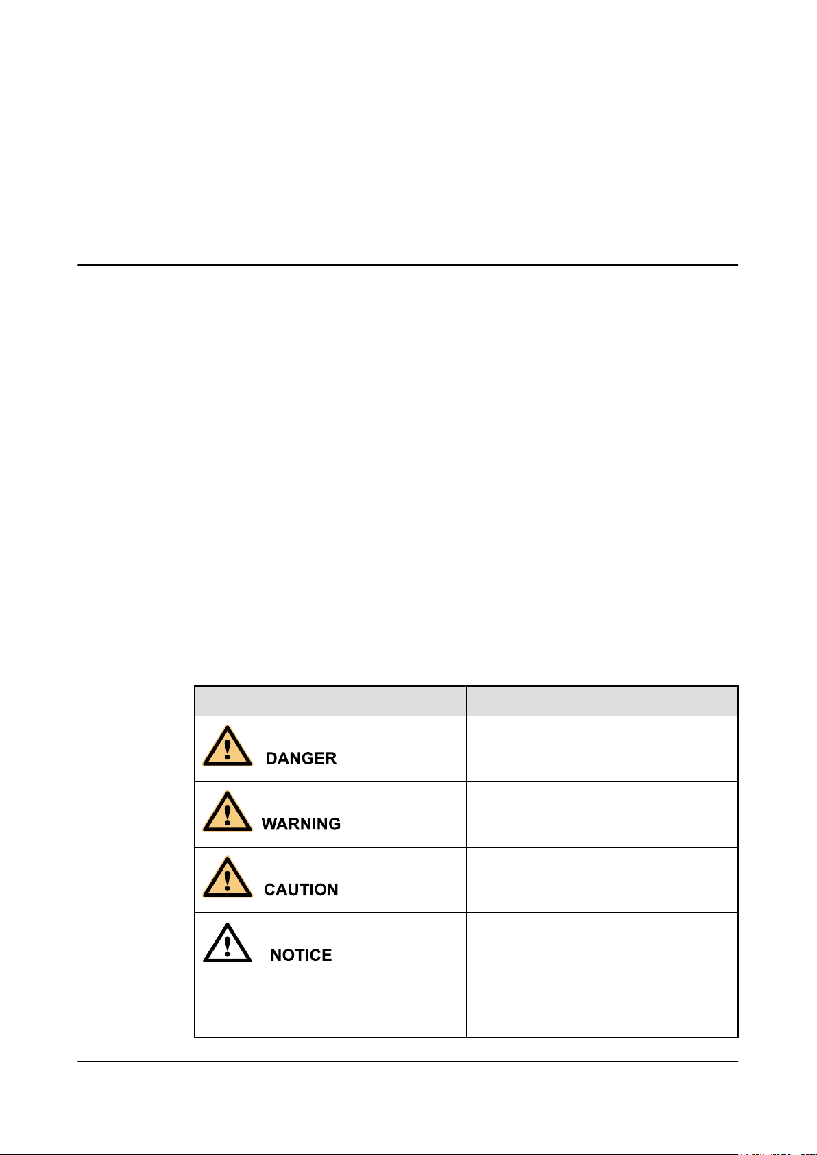
The symbols that may be found in this document are defined as follows.
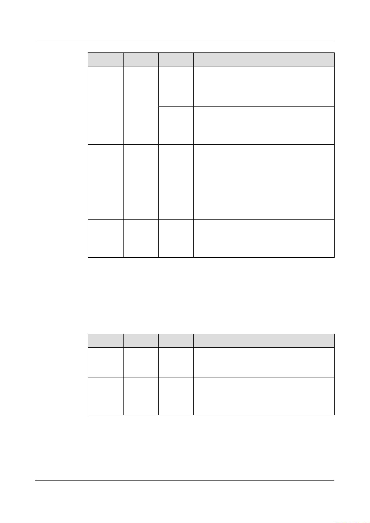
Symbol Description
Indicates an imminently hazardous situation
which, if not avoided, will result in death or
serious injury.
Indicates a potentially hazardous situation
which, if not avoided, could result in death or
serious injury.
Indicates a potentially hazardous situation
which, if not avoided, may result in minor or
moderate injury.
Indicates a potentially hazardous situation
which, if not avoided, could result in
equipment damage, data loss, performance
deterioration, or unanticipated results.
NOTICE is used to address practices not
related to personal injury.
Issue 03 (2015-05-18) Huawei Proprietary and Confidential
Copyright © Huawei Technologies Co., Ltd.
ii

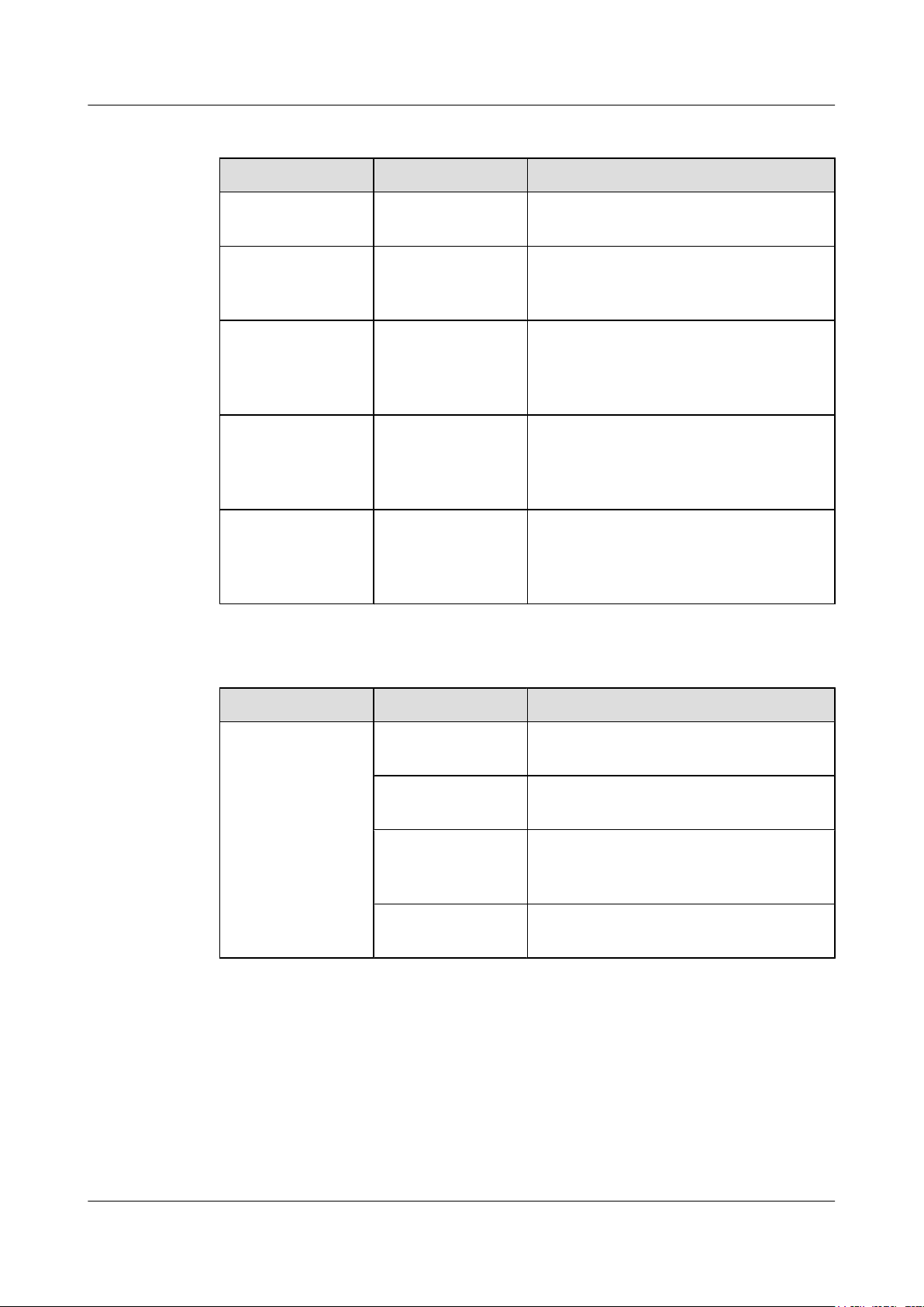
NOTE
Huawei AP8030DN & AP8130DN
Hardware Installation and Maintenance Guide
Symbol Description
Change History
Changes between document issues are cumulative. The latest document issue contains all
changes made in previous issues.
Issue 03 (2015-05-18)
This version has the following updates:
About This Document
Calls attention to important information, best
practices and tips.
NOTE is used to address information not
related to personal injury, equipment damage,
and environment deterioration.
The following information is modified:
l Updated the mounting bracket.
l Optimized the cabling diagram.
l Added the command to check AP running status in V200R006C00.
l Added descriptions about PoE fault troubleshooting.
Issue 02 (2014-12-05)
This version has the following updates:
The following information is modified:
l Installation of the angle adjusting component with AP8030DN is added.
The following information is added:
l 1.4 Ordering Information.
Issue 01 (2014-08-20)
Initial commercial release
Issue 03 (2015-05-18) Huawei Proprietary and Confidential
Copyright © Huawei Technologies Co., Ltd.
iii

Huawei AP8030DN & AP8130DN
Hardware Installation and Maintenance Guide
Contents
Contents
About This Document.....................................................................................................................ii
1 AP8130DN & AP8030DN Overview..........................................................................................1
1.1 Device Structure.............................................................................................................................................................2
1.2 Indicator Description......................................................................................................................................................4
1.3 Basic Specifications........................................................................................................................................................7
1.4 Ordering Information......................................................................................................................................................8
2 AP Installation.............................................................................................................................10
2.1 Preparing for Installation..............................................................................................................................................11
2.2 Installation Flowchart...................................................................................................................................................12
2.3 Unpacking the Equipment............................................................................................................................................13
2.4 Determining the Installation Position...........................................................................................................................14
2.5 Installing the AP...........................................................................................................................................................16
2.5.1 Wall Mounting...........................................................................................................................................................16
2.5.2 Pole Mounting...........................................................................................................................................................23
2.6 Connecting Cables........................................................................................................................................................28
2.6.1 Connecting RF Cables...............................................................................................................................................28
2.6.2 Connecting Optical Fibers and Network Cables.......................................................................................................30
2.6.3 Connecting Ground Cables........................................................................................................................................33
2.6.4 Installing Outdoor Antennas......................................................................................................................................36
2.7 Installing the Security Lock..........................................................................................................................................39
2.8 Checking the AP After Installation..............................................................................................................................40
2.9 Powering on the AP......................................................................................................................................................40
3 Logging In to the AP...................................................................................................................41
3.1 Logging In to the AP Through the Console Port..........................................................................................................42
3.2 Logging In to the AP Using STelnet............................................................................................................................42
3.3 Logging In to the AP Using Telnet..............................................................................................................................43
3.4 Logging In to the AP Using a Web Client....................................................................................................................44
4 Hardware Failures.......................................................................................................................46
4.1 An device Fails to Be Powered On...............................................................................................................................47
4.2 An Optical Interface Cannot Turn Up..........................................................................................................................47
5 Appendix.......................................................................................................................................49
Issue 03 (2015-05-18) Huawei Proprietary and Confidential
Copyright © Huawei Technologies Co., Ltd.
iv

Huawei AP8030DN & AP8130DN
Hardware Installation and Maintenance Guide Contents
5.1 On-site Cable Assembly and Installation.....................................................................................................................50
5.1.1 Cable Assembly Precautions.....................................................................................................................................50
5.1.2 Assembling Power Cables.........................................................................................................................................51
5.1.3 Assembling Ethernet Cables......................................................................................................................................59
5.1.4 Installing Cable Accessories......................................................................................................................................73
5.1.5 Replacing the Mold of the Crimping Pliers...............................................................................................................89
5.2 Environmental Requirements for Device Operation....................................................................................................92
5.2.1 Environmental Requirements for an Equipment Room............................................................................................92
5.2.2 Requirements for Power Supply..............................................................................................................................100
5.3 Equipment Grounding Specifications.........................................................................................................................103
5.3.1 General Grounding Specifications...........................................................................................................................103
5.3.2 Grounding Specifications for an Equipment Room................................................................................................103
5.3.3 Grounding Specifications for Devices.....................................................................................................................103
5.3.4 Grounding Specifications for Communications Power Supply...............................................................................104
5.3.5 Grounding Specifications for Signal Cables...........................................................................................................105
5.3.6 Specifications for Laying Out Grounding Cables...................................................................................................105
5.4 Engineering Labels for Cables...................................................................................................................................106
5.4.1 Introduction to Labels..............................................................................................................................................106
5.4.2 Engineering Labels for Optical Fibers.....................................................................................................................114
5.4.3 Engineering Labels for Network Cables.................................................................................................................117
5.4.4 Engineering Labels for User Cables........................................................................................................................118
5.4.5 Engineering Labels for Power Cables.....................................................................................................................119
5.5 Guide to Using Optical Modules................................................................................................................................122
5.6 Fault Tag.....................................................................................................................................................................125
Issue 03 (2015-05-18) Huawei Proprietary and Confidential
Copyright © Huawei Technologies Co., Ltd.
v

Huawei AP8030DN & AP8130DN
Hardware Installation and Maintenance Guide 1 AP8130DN & AP8030DN Overview
1 AP8130DN & AP8030DN Overview
About This Chapter
Huawei AP8030DN and AP8130DN is the latest-generation 802.11ac outdoor access point (AP)
that supports 3x3 MIMO. The AP is physically hardened and features enhanced outdoor
coverage performance. It supports 2.4 GHz and 5 GHz frequency bands, complies with IEEE
802.11a/b/g/n/ac, and can work as wireless bridges. The AP can provide services simultaneously
on the 2.4 GHz and 5 GHz frequency bands to support more access users. It provides
comprehensive service support capabilities and features high reliability, high security, simple
network deployment, automatic AC discovery and configuration, and real-time management
and maintenance, which meets requirements of outdoor deployment.
Huawei AP8030DNs and AP8130DNs comply with IP67 dustproof and waterproof protection
standards, applicable to coverage scenarios (for example, squares, pedestrian streets, and
amusement parks) and bridging scenarios (for example, wireless harbors, data backhaul, video
surveillance, and train-to-ground backhaul).
1.1 Device Structure
1.2 Indicator Description
1.3 Basic Specifications
1.4 Ordering Information
To place an order, contact the Huawei local office.
Issue 03 (2015-05-18) Huawei Proprietary and Confidential
Copyright © Huawei Technologies Co., Ltd.
1
GE0/PoE
GE1 SFP
SYS
Link/ACT1
Wireless1
Link/ACT0
Wireless0
Link/ACT2
1 3
2
9
Console
Default
6
7
8
5G
GE0/PoE
GE1
SFP
SYS
2.4G/5G
Link/ACT1
Wireless1
Link/ACT0
Wireless0
Link/ACT2
1 3
2
4 5
10 9
10
2.4G/5G
2.4G/5G 5G
5G
5
4
10
Huawei AP8030DN & AP8130DN
Hardware Installation and Maintenance Guide 1 AP8130DN & AP8030DN Overview
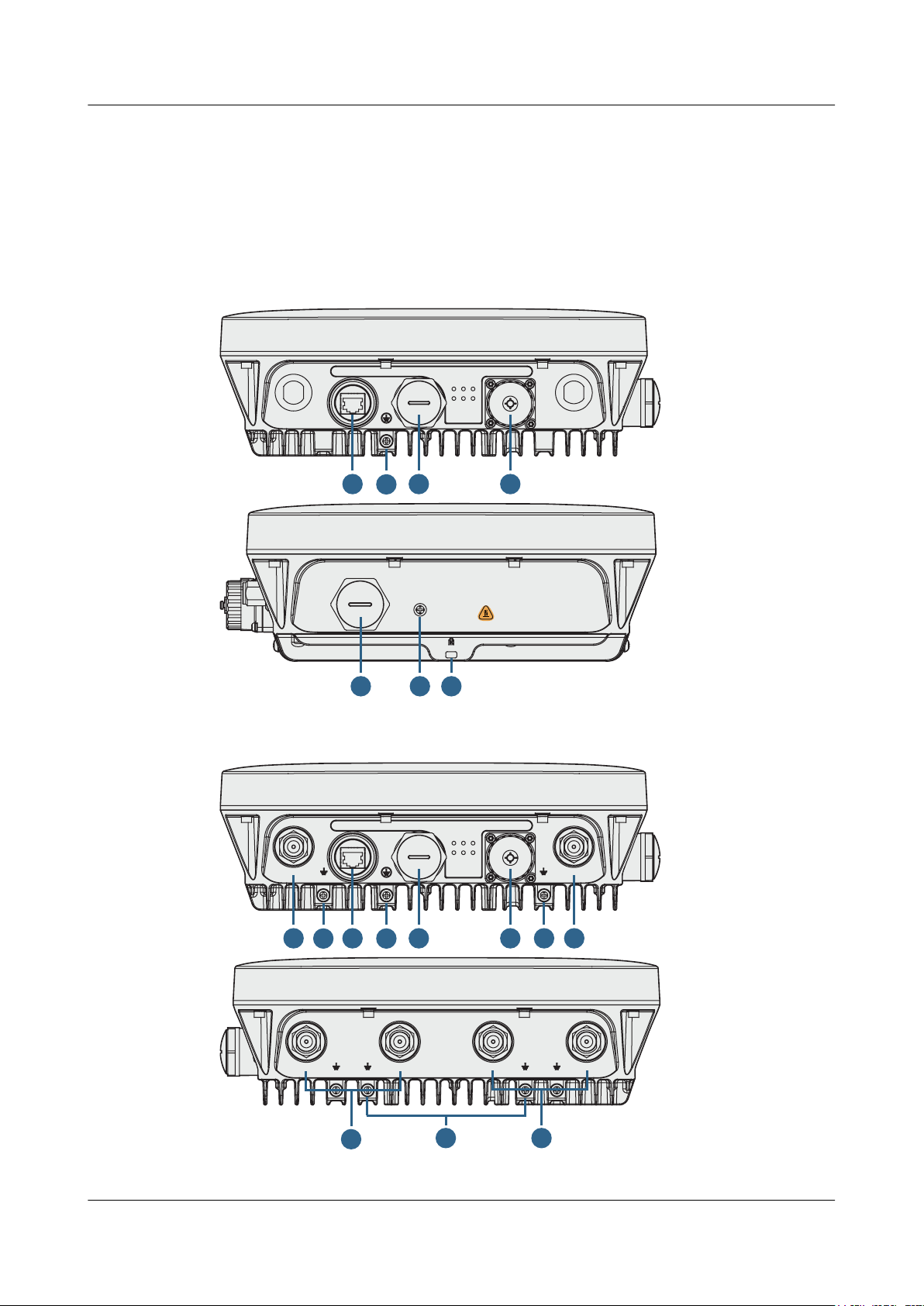
1.1 Device Structure
Figure 1-1 and Figure 1-2 shows the appearance of the AP8030DN and AP8130DN.
Figure 1-1 AP8030DN appearance
Figure 1-2 AP8130DN appearance
Issue 03 (2015-05-18) Huawei Proprietary and Confidential
Copyright © Huawei Technologies Co., Ltd.
2
Console
Default
6
7
8
Huawei AP8030DN & AP8130DN
Hardware Installation and Maintenance Guide
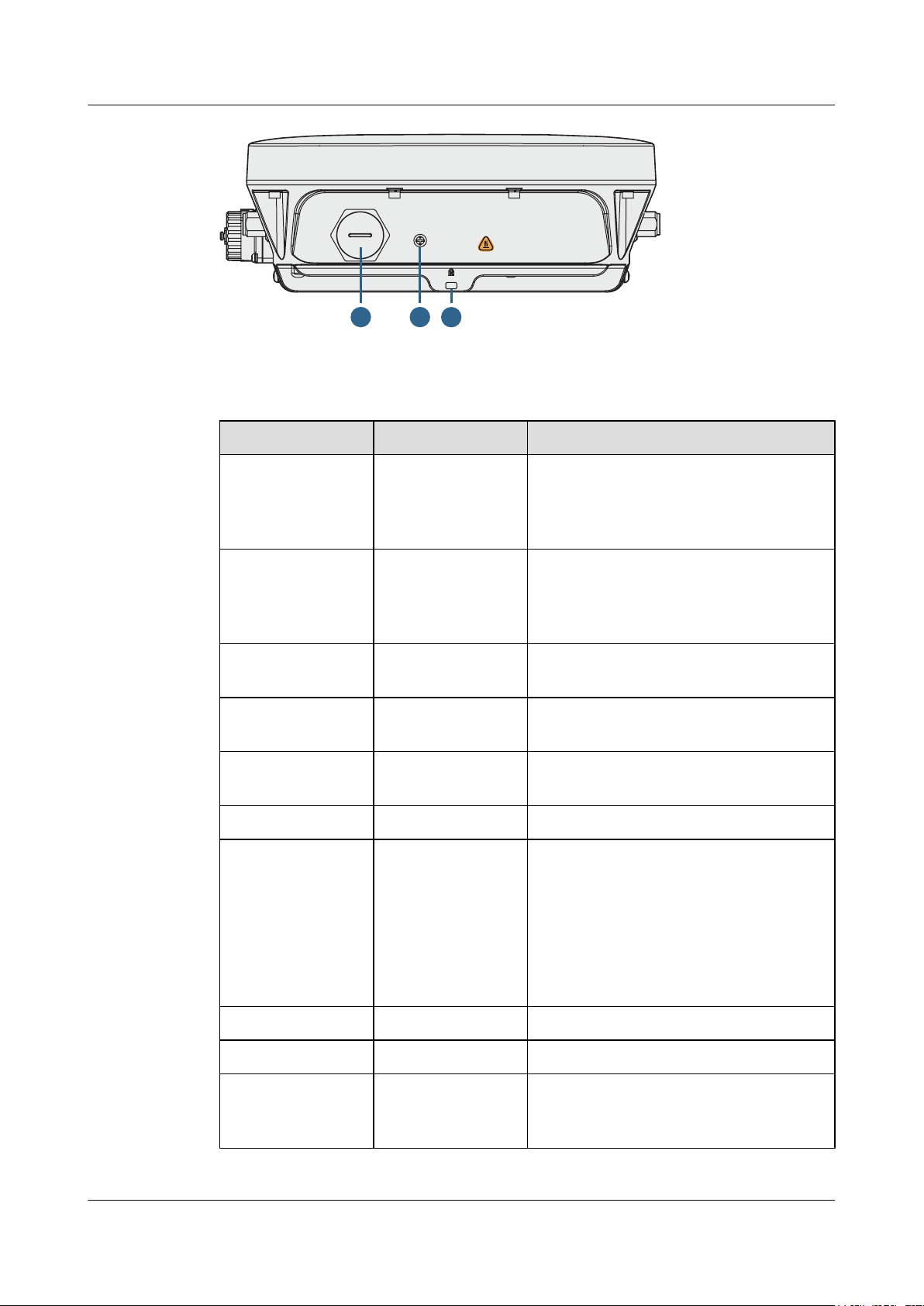
Table 1-1 describes interfaces on the AP8030DN and AP8130DN.
Table 1-1 Descriptions of interfaces
No. Name Description
1 GE0/PoE 10/100/1000M bit/s interface: connects to the
1 AP8130DN & AP8030DN Overview
wired Ethernet. The interface can connect to
a PoE power supply to provide power for the
AP.
2 GE1 10/100/1000M bit/s interface: connects to the
wired Ethernet. The interface can't connect to
a PoE power supply to provide power for the
AP.
3 SFP Connects an optical fiber to the AP. An
optical module must be installed first.
4 5G antenna interface Connects a 2.4GHz antenna to the AP to send
and receive service signals.
5 2.4G or 5G antenna
interface
Connects a 2.4GHz or 5GHz antenna to the
AP to send and receive service signals.
6 Console Console: Console interface
7 Default Reset button: restores factory settings and
restarts the AP if you hold down the Reset
button for more than 3 seconds.
NOTE
The Reset button is protected by a waterproof
screw. Before pressing the Reset button, remove
the waterproof screw. Keep the screw properly and
install it again after pressing the Reset button.
8 Security slot Connects to a security lock.
9 Device ground screw Connects a ground cable to the AP.
10 Ground screw for the
surge protective
Connects the AP to the ground point of an
external surge protective device.
device
Issue 03 (2015-05-18) Huawei Proprietary and Confidential
Copyright © Huawei Technologies Co., Ltd.
3
GE1
SYS
Link/A C T1
Wire less1
Link/A C T0
Wire less0
Link/A C T2
Huawei AP8030DN & AP8130DN
Hardware Installation and Maintenance Guide 1 AP8130DN & AP8030DN Overview
NOTE
The AP8130DN offers two internal DB9 ports, which have similar functions as external GE ports. In device
usage, you are advised to connect the device through the GE ports but not the DB9 ports.
CAUTION
There is a scald warning label attached on the device, warning you not to touch the device after
the device has been operating for a long time.
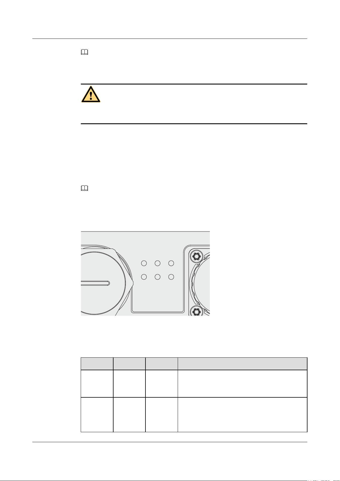
1.2 Indicator Description
The AP8030DN and AP8130DN provides multiple indicators: SYS indicator, Link/ACT
indicator, and Wireless indicator. The following tables describe indicators on the AP8030DN
and AP8130DN.
NOTE
SYS indicator
l Indicator colors may vary slightly at different temperature.
l After a Fit AP is powered on, you can run the led off command on the AC to turn off all AP indicators.
To restore the indicators to normal working status, run the led on command. Indicators on a Fat AP
cannot be turned off using the led off command.
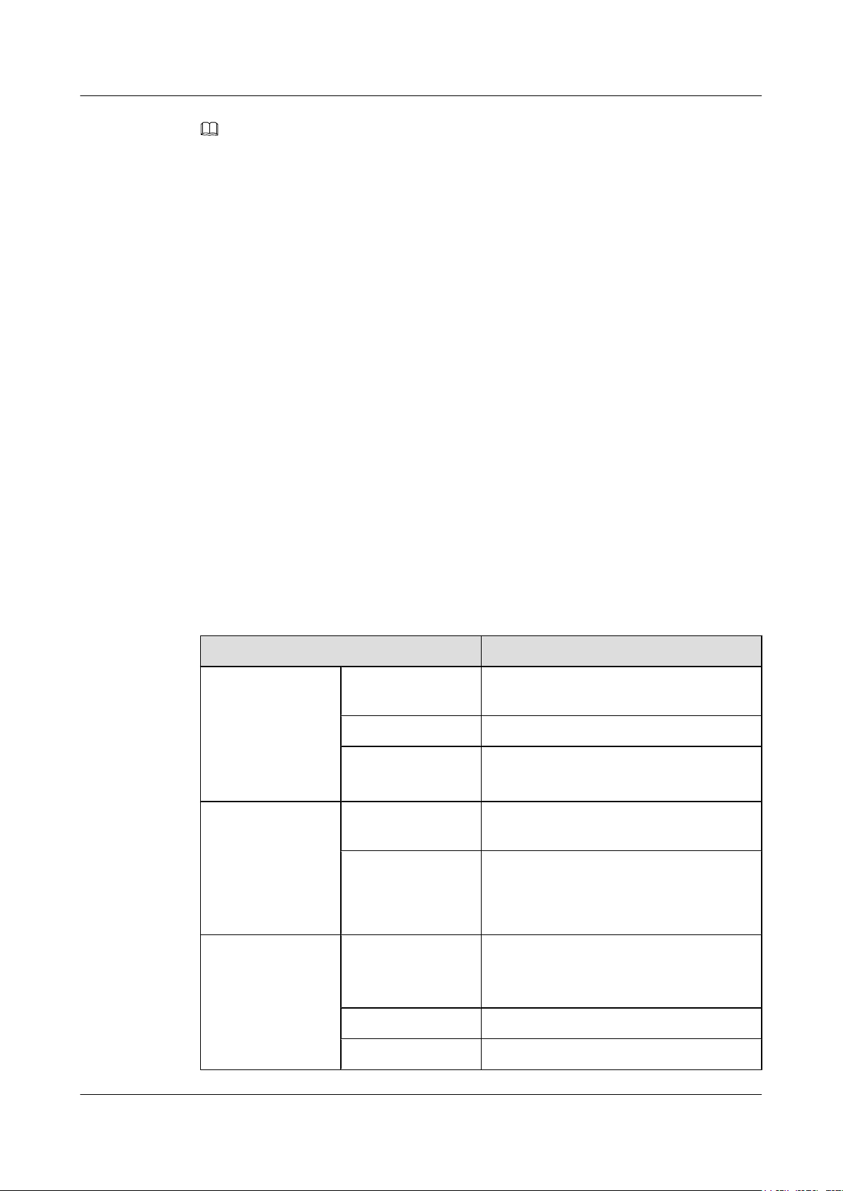
Table 1-2 Descriptions about the SYS indicator
Type Color Status Description
Default
status after
power-on
Software
startup
Issue 03 (2015-05-18) Huawei Proprietary and Confidential
status
Green Steady on The AP is just powered on and the software is not
started yet.
Green Steady on
after
blinking
once
Copyright © Huawei Technologies Co., Ltd.
After the system is reset and starts uploading the
software, the indicator blinks green once. Until the
software is uploaded and started, the indicator
remains steady green.
4
Huawei AP8030DN & AP8130DN
Hardware Installation and Maintenance Guide
Type Color Status Description
1 AP8130DN & AP8030DN Overview
Running
status
Alarm Green Blinking
Fault Red Steady on A fault that affects services has occurred, such as a
Green Blinking
once every
2s (0.5 Hz)
Blinking
once every
5s (0.2 Hz)
once every
0.25s (4
Hz)
l The system is running properly, the Ethernet
connection is normal, and STAs are associated
with the AP.
l The system enters the Uboot CLI.
The system is running properly, the Ethernet
connection is normal, and no STA is associated with
the AP. The system is in low power consumption
state.
l The software is being upgraded.
l After the software is uploaded and started, the AP
working in Fit AP mode requests to go online on
the AC and maintains this state until it goes
online successfully on the AC (before the
CAPWAP link is established).
l The AP working in Fit AP mode fails to go online
on the AC (the CAPWAP link disconnects).
DRAM detection failure or system software loading
failure. The fault cannot be automatically rectified
and must be rectified manually.
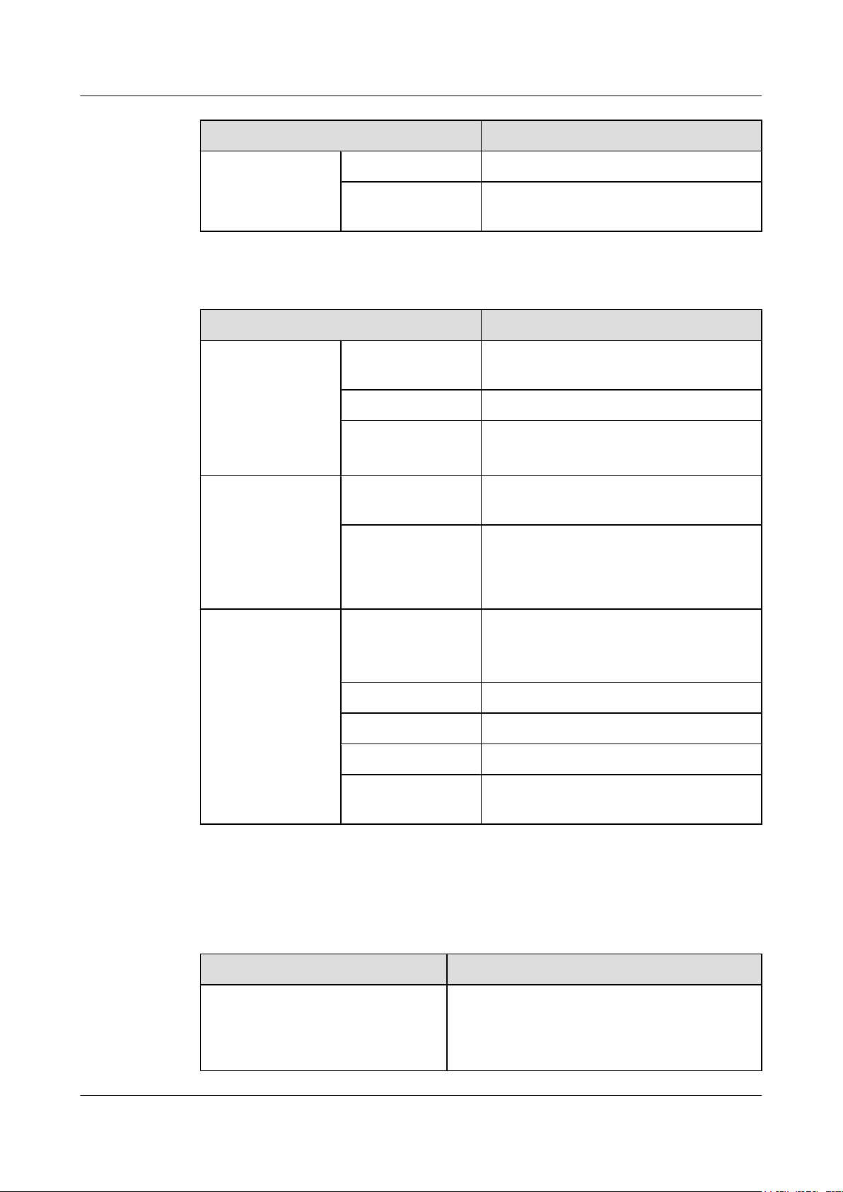
Link/ACT indicators
Link/ACT indicators consist of Link/ACT0, Link/ACT1, and Link/ACT2, showing link status
of interfaces GE0/PoE, GE1, SFP respectively.
Table 1-3 Descriptions about the Link/ACT indicators
Type Color Status Description
LINK Green Steady on The system is running properly, the Ethernet
ACT Green Blinking The system is running properly, the Ethernet
Wireless indicators
connection is normal, and no data is being
transmitted.
connection is normal, and the AP is transmitting
data. The indicator blinks more quickly when more
data is being transmitted.
Wireless indicators consist of Wireless0 and Wireless1, showing wireless link status of the 5
GHz and 2.4/5 GHz radio interfaces respectively.
Issue 03 (2015-05-18) Huawei Proprietary and Confidential
Copyright © Huawei Technologies Co., Ltd.
5
Huawei AP8030DN & AP8130DN
Hardware Installation and Maintenance Guide
Table 1-4 Traffic volume indicator
Color Status Description
Yellow/green Off Radios are disabled, and no STA is connected
Yellow/green Steady on The AP has STAs connected to the 2.4 GHz
Green Blinking The AP has STAs connected to the 2.4 GHz
Yellow Blinking The AP has STAs connected to the 5 GHz
1 AP8130DN & AP8030DN Overview
to the AP.
radio or 5 GHz radio, but no data is being
transmitted.
radio and is transmitting data. The indicator
blinks more quickly when more data is being
transmitted.
radio and is transmitting data. The indicator
blinks more quickly when more data is being
transmitted.
Yellow/green Blinking
alternatively
The AP has STAs connected to both the 2.4
GHz radio and 5 GHz radio. The indicator
blinks more quickly when more data is being
transmitted.
Table 1-5 Wireless bridge indicator
Color Status Description
Yellow/green Off The AP is not transmitting or receiving data
or the signal strength is extremely low.
Blinking once every
2s (0.5 Hz)
Blinking green once
every 0.25 seconds (4
The AP is transmitting or receiving data
normally, and the signal strength is low.
The AP is transmitting or receiving data
normally, and the signal strength is medium.
Hz)
Steady on The AP is transmitting or receiving data
normally, and the signal strength is high.
Issue 03 (2015-05-18) Huawei Proprietary and Confidential
Copyright © Huawei Technologies Co., Ltd.
6
Huawei AP8030DN & AP8130DN
Hardware Installation and Maintenance Guide 1 AP8130DN & AP8030DN Overview
NOTE
When the WDS/mesh function is enabled on an AP, the blinking frequency of its Wireless LED indicates
the receive signal strength on the WDS/mesh connection by default. After you connect an AP to a WDS/
mesh network, you can run the wifi-light { signal-strength | traffic } command on the AC to make the
Wireless LED blinking frequency indicate receive signal strength or service traffic rate.
l wifi-light signal-strength:
l If the mesh function is enabled on the AP, the blinking frequency of the Wireless LED reflects
the weakest signal strength of all neighboring APs.
l If WDS is enabled on an AP, the blinking frequency of the Wireless LED reflects the strength
of signals received from a WDS AP.
l If the AP works in leaf mode, the blinking frequency of the Wireless LED reflects the strength
of signals received from a middle AP.
l If the AP works in middle mode, the blinking frequency of the Wireless LED reflects the
strength of signals received from a root AP.
l If the AP works in root mode, the blinking frequency of the Wireless LED reflects the weakest
signal strength of middle APs.
l wifi-light traffic: allows the Wireless LED to reflect the service traffic volume on the radio.
The Fat AP does not support WDS/Mesh functions; therefore, the Wireless indicator of the Fat AP does
not indicate the signal strength.
1.3 Basic Specifications
Table 1-6 and Table 1-7 provides basic specifications of the AP8030DN and AP8130DN.
Table 1-6 Basic Specifications of the AP8030DN
Item Description
Technical
specifications
Power specifications Power input PoE power supply: -48 V DC (in compliance
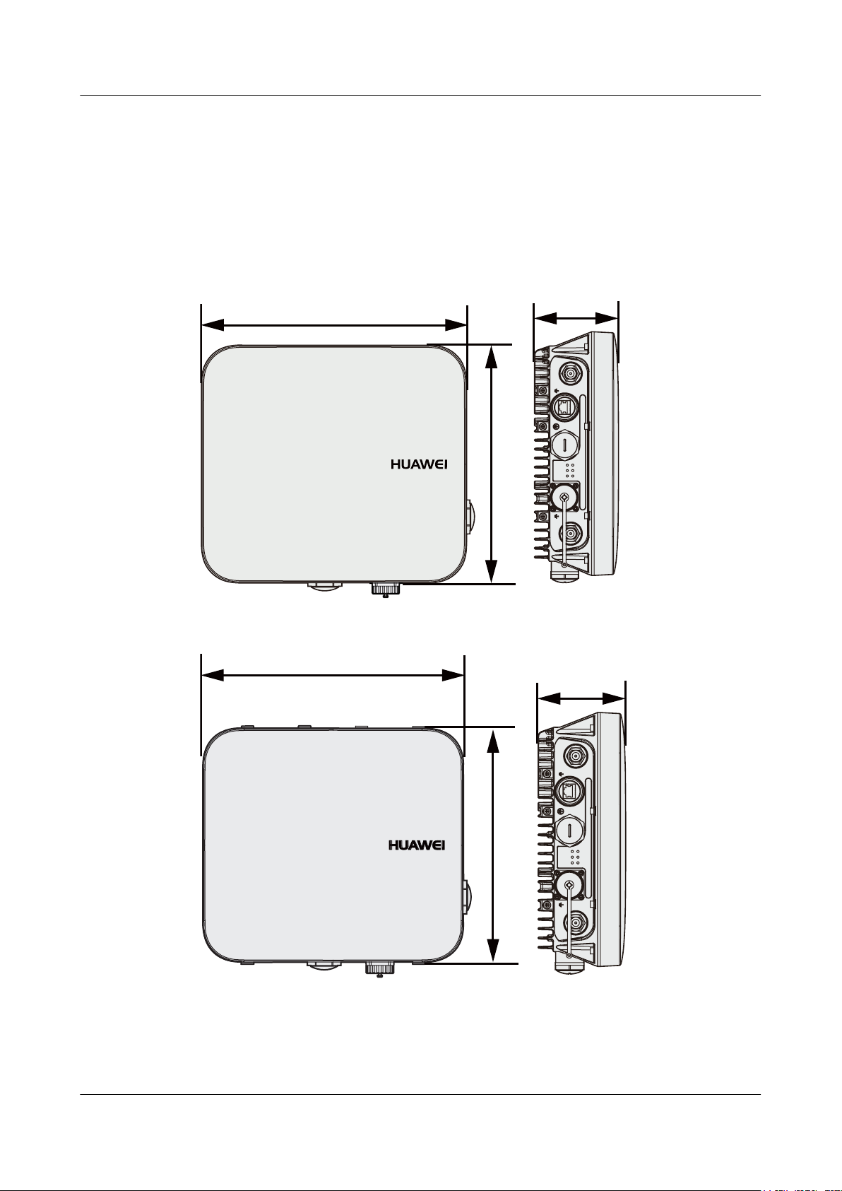
Dimensions (H x W xD)100 mm x 290 mm x 260 mm
Weight 3.6 kg
System memory
l 256 MB DDR3
l 64 MB Flash
with IEEE 802.3at)
Maximum power
consumption
20.1 W
NOTE
The actual maximum power consumption depends
on local laws and regulations.
Environment
specifications
Operating
temperature
-60 m to +1800 m: -40°C to +60°C
1800 m to 5000 m: Temperature decreases by
1°C every time the altitude increases 220 m.
Storage temperature -40°C to +70°C
Operating humidity 0% to 100% (non-condensing)
Issue 03 (2015-05-18) Huawei Proprietary and Confidential
Copyright © Huawei Technologies Co., Ltd.
7
Huawei AP8030DN & AP8130DN
Hardware Installation and Maintenance Guide 1 AP8130DN & AP8030DN Overview
Item Description
IP rating IP67
Atmospheric
pressure
Table 1-7 Basic Specifications of the AP8130DN
Item Description
Technical
specifications
Power specifications Power input PoE power supply: -48 V DC (in compliance
Dimensions (H x W xD)100 mm x 290 mm x 260 mm
Weight 4.0 kg
System memory
Maximum power
consumption
53 kPa to 106 kPa
l 256 MB DDR3
l 64 MB Flash
with IEEE 802.3at)
22.4 W
NOTE
The actual maximum power consumption depends
on local laws and regulations.
Environment
specifications
Operating
temperature
Storage temperature -40°C to +70°C
Operating humidity 0% to 100% (non-condensing)
IP rating IP67
Atmospheric
pressure
1.4 Ordering Information
To place an order, contact the Huawei local office.
Part Number Description
02350ALD Assembling
-60 m to +1800 m: -40°C to +60°C
1800 m to 5000 m: Temperature decreases by
1°C every time the altitude increases 220 m.
53 kPa to 106 kPa
Components,AP8030DN,AP8030DN,AP8030DN
Mainframe(11ac,General AP Outdoor,3x3 Double
Frequency,Built-in Antenna)
Issue 03 (2015-05-18) Huawei Proprietary and Confidential
Copyright © Huawei Technologies Co., Ltd.
8

Huawei AP8030DN & AP8130DN
Hardware Installation and Maintenance Guide 1 AP8130DN & AP8030DN Overview
Part Number Description
02359462 Assembling
Components,AP8130DN,AP8130DN,AP8130DN
Mainframe(11ac,General AP Outdoor,3x3 Double
Frequency,External Antenna)
Issue 03 (2015-05-18) Huawei Proprietary and Confidential
Copyright © Huawei Technologies Co., Ltd.
9

Huawei AP8030DN & AP8130DN
Hardware Installation and Maintenance Guide 2 AP Installation
2 AP Installation
About This Chapter
2.1 Preparing for Installation
2.2 Installation Flowchart
2.3 Unpacking the Equipment
2.4 Determining the Installation Position
2.5 Installing the AP
2.6 Connecting Cables
2.7 Installing the Security Lock
2.8 Checking the AP After Installation
2.9 Powering on the AP
Issue 03 (2015-05-18) Huawei Proprietary and Confidential
Copyright © Huawei Technologies Co., Ltd.
10
Huawei AP8030DN & AP8130DN
Hardware Installation and Maintenance Guide 2 AP Installation
2.1 Preparing for Installation
This section describes safety precautions and tool preparations for AP installation.
Safety Precautions
l Take proper measures to prevent injuries and device damage.
l Place the device in a dry and flat position away from any liquid and prevent the device from
slipping.
l Keep the device clean.
l Do not put the device and tools in the aisles.
CAUTION
Only the qualified personnel are permitted to install and remove the device and its accessories.
Before installation and operation, read the safety precautions carefully.
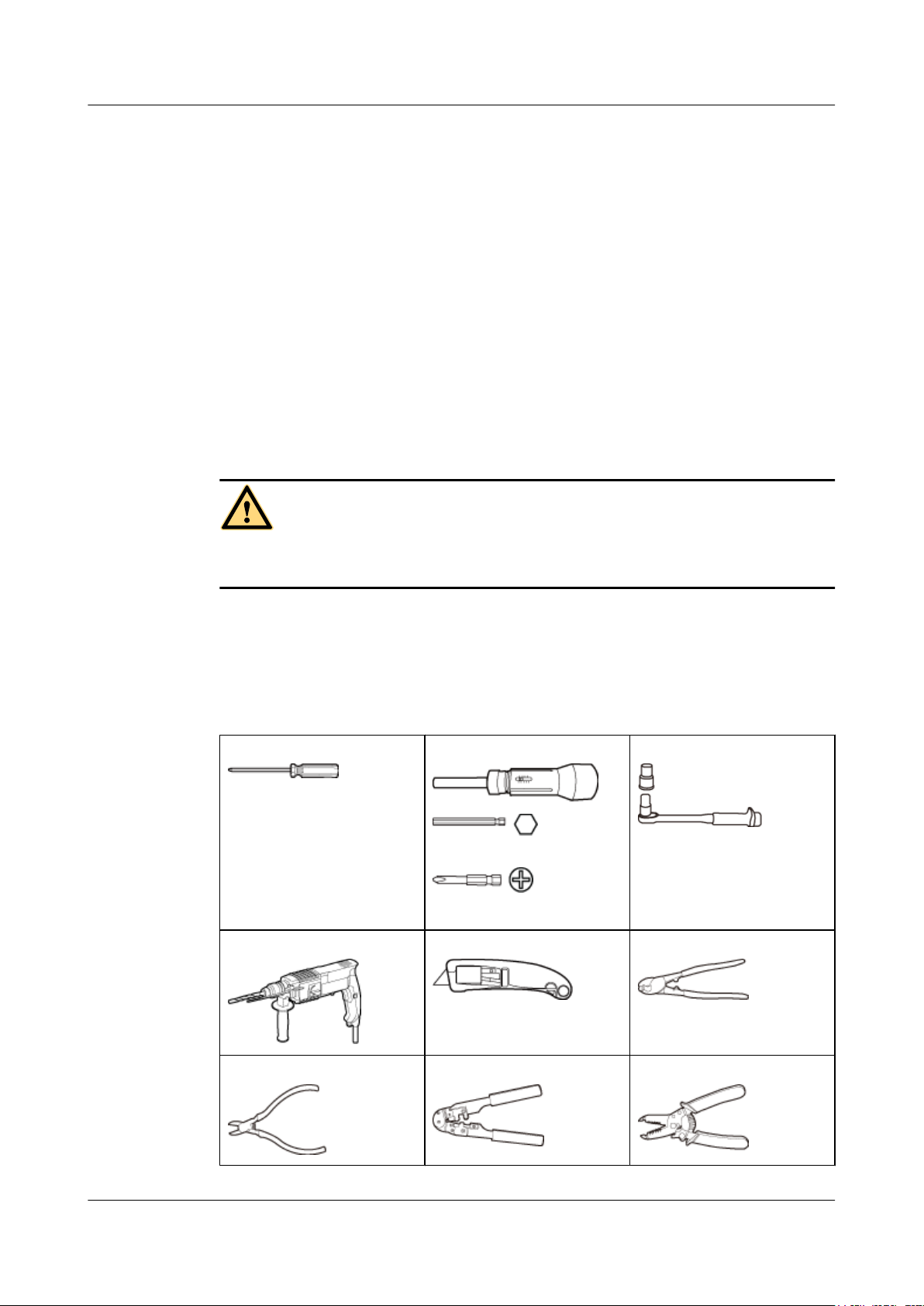
Tool Preparation
To install the APs, prepare tools listed in Table 2-1.
Table 2-1 Tools
Phillips screwdriver (M4)
Hammer drill (φ8) Utility knife Cable cutter
Torque screwdriver
3mm/5mm
(M3-M6)
Torque socket (M6)
Diagonal pliers RJ45 crimping tool Wire stripper
Issue 03 (2015-05-18) Huawei Proprietary and Confidential
Copyright © Huawei Technologies Co., Ltd.
11
Huawei AP8030DN & AP8130DN
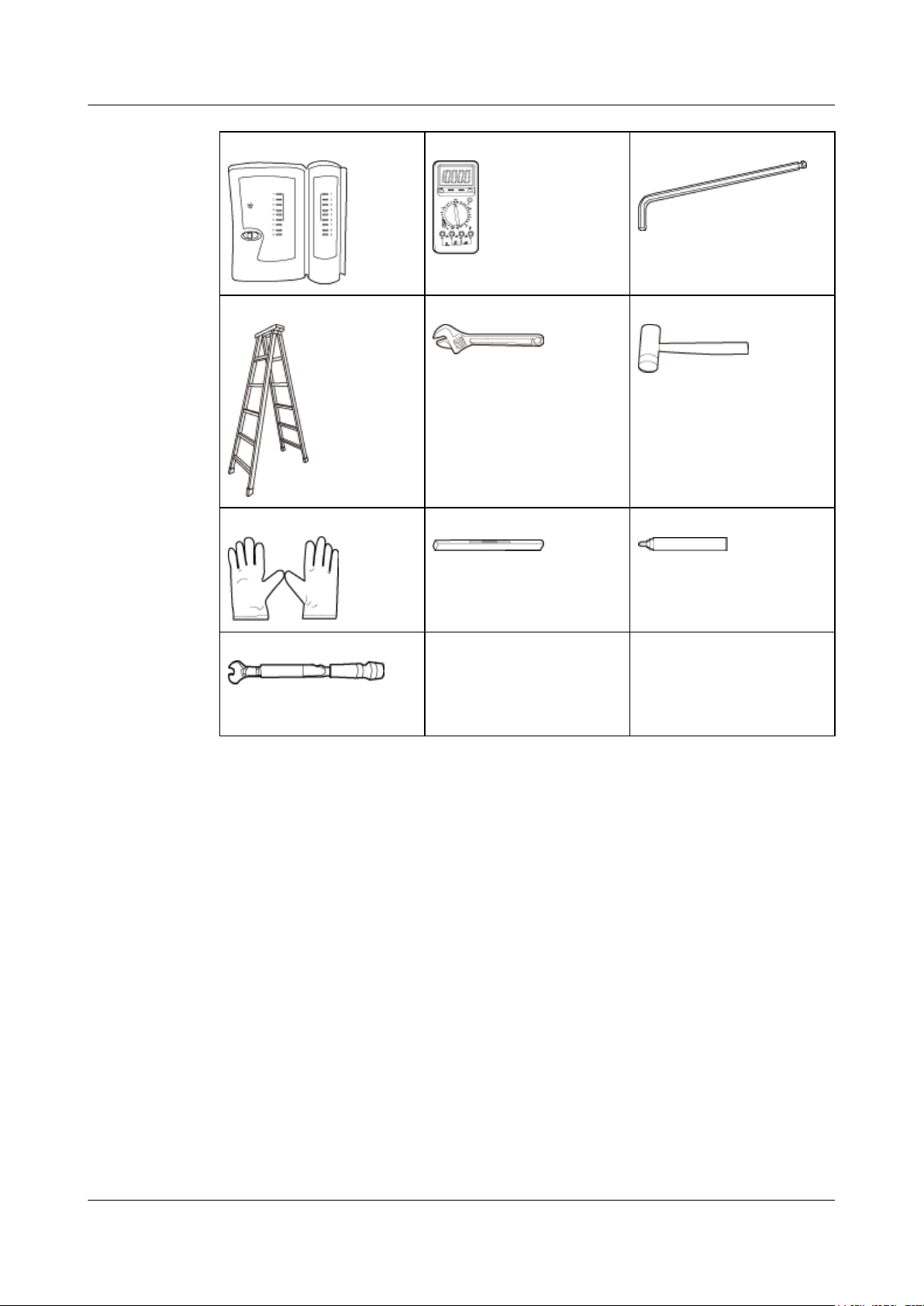
Hardware Installation and Maintenance Guide 2 AP Installation
Network cable tester Multimeter Inner hexagon wrench (M6)
Ladder Adjustable wrench Rubber mallet
ESD gloves Level Marker
Torque wrench
(Use an N-type open-end
torque wrench.)
2.2 Installation Flowchart
Figure 2-1 shows the flowchart for installing an AP8130DN.
Issue 03 (2015-05-18) Huawei Proprietary and Confidential
Copyright © Huawei Technologies Co., Ltd.
12
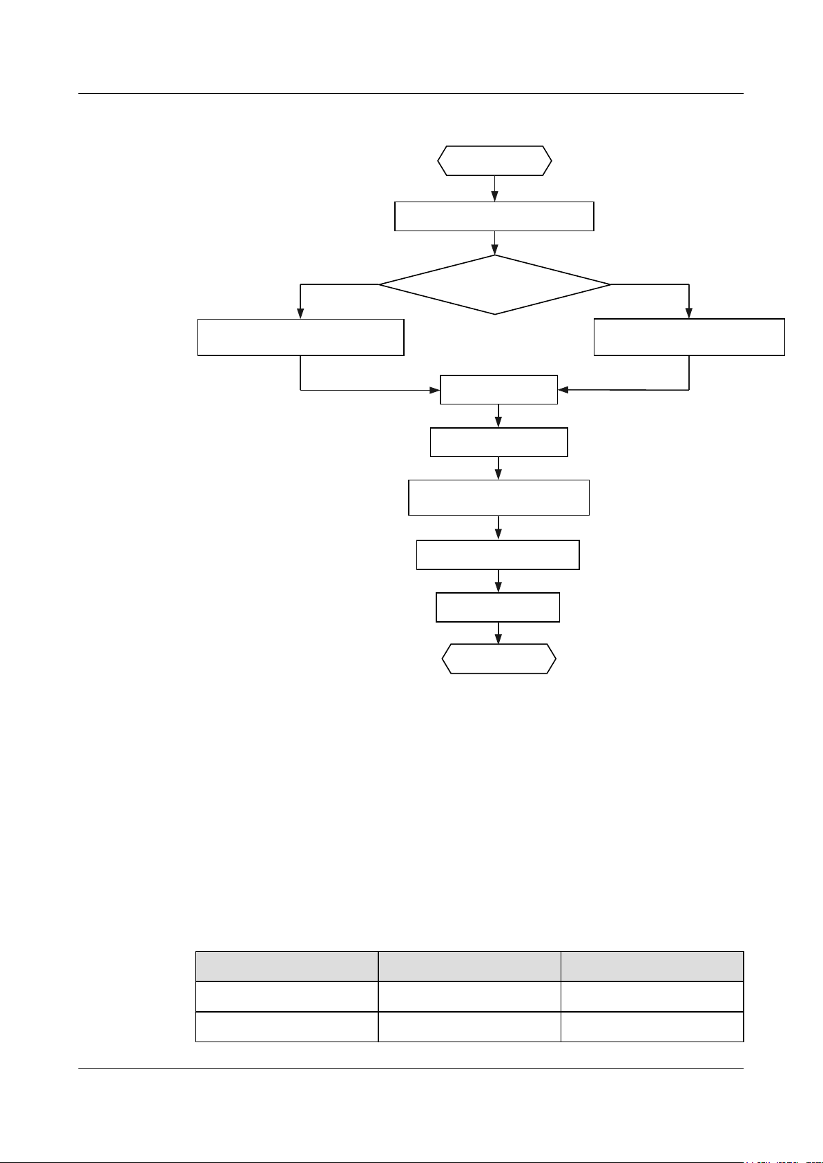
Determine the
installation location
Start
Check before installation
Fix the wall-mounting
Bracket against the wall
Fix the wall-mounting
Bracket against the pole
Install the AP
Connect the cable
Connect the security lock
to the lock hole
Power on the AP
Check after installation
End
Against the wall
Against the pole
Huawei AP8030DN & AP8130DN
Hardware Installation and Maintenance Guide 2 AP Installation
Figure 2-1 Installation flowchart
2.3 Unpacking the Equipment
Before unpacking the carton, ensure that the packing carton is intact and not damaged or soaked.
Stop unpacking if the equipment is rusted or soggy. Then, investigate causes and contact the
supplier.
After unpacking, check items in the carton against the packing list. If any item is missing, contact
the supplier or agent.
Usually, the packing carton contains all items listed in the packing list shown in Table 2-2.
Table 2-2 Packing list
No. Item Quantity
1 AP device 1
2 Mounting bracket 1
Issue 03 (2015-05-18) Huawei Proprietary and Confidential
Copyright © Huawei Technologies Co., Ltd.
13
Huawei AP8030DN & AP8130DN
Hardware Installation and Maintenance Guide
No. Item Quantity
3 PG connector 2
2 AP Installation
4 M4x12 hexagon socket head
cap screw
5 Expansion bolt 2
6 Hose clamp 2
7 OT terminal
8 Casting Adjustable-degree
1
solid
9 Quick Start Guide 1
Pay attention to the following:
l Only the AP8030DN carton contains the casting adjustable-degree solid.
l Figures in the document are for reference only and may be different from actual devices.
l Remove the protective film on the AP surface before installation to prevent electrostatic
discharge.
4
l M4: 2
l M6: 1
l M8: 1
1
2.4 Determining the Installation Position
When determining the AP installation position, comply with the following rules:
l Do not install the AP in the place with high temperature, dust, noxious gas, or unstable
voltage, or in the place near flammable or explosive materials and interference sources such
as a large radar station, radio station, and transformer station.
l Install the AP in a site that is free from leaking or dripping water, heavy dew, and humidity,
and take protective measures to prevent water from flowing into the equipment along the
cable.
l Install the AP in a hidden position that does not affect daily lives and work of residents.
l Make the engineering design by fully considering such factors as hydrology, geology,
earthquake, electric power, and traffic. The selected site should comply with the
environment design specifications of communications equipment.
The AP8030DN and AP8130DN can be installed against a pole or a wall. The AP must be
installed by professional installation personnel, and the installation position is determined
according to the site survey.
Figure 2-2 and Figure 2-3 shows dimensions of the AP8030DN and AP8130DN.
Issue 03 (2015-05-18) Huawei Proprietary and Confidential
Copyright © Huawei Technologies Co., Ltd.
14
290
100
*
*(3R(
*( 6)3
6<6
**
/LQN$&7
:LUHOHVV
/LQN$&7
:LUHOHVV
/LQN$&7
260
100
*
*(3R(
*( 6)3
6<6
**
/LQN$&7
:LUHOHVV
/LQN$&7
:LUHOHVV
/LQN$&7
260
290
Huawei AP8030DN & AP8130DN
Hardware Installation and Maintenance Guide
Figure 2-2 Dimensions of an AP8030DN (unit: mm)
2 AP Installation
Figure 2-3 Dimensions of an AP8130DN (unit: mm)
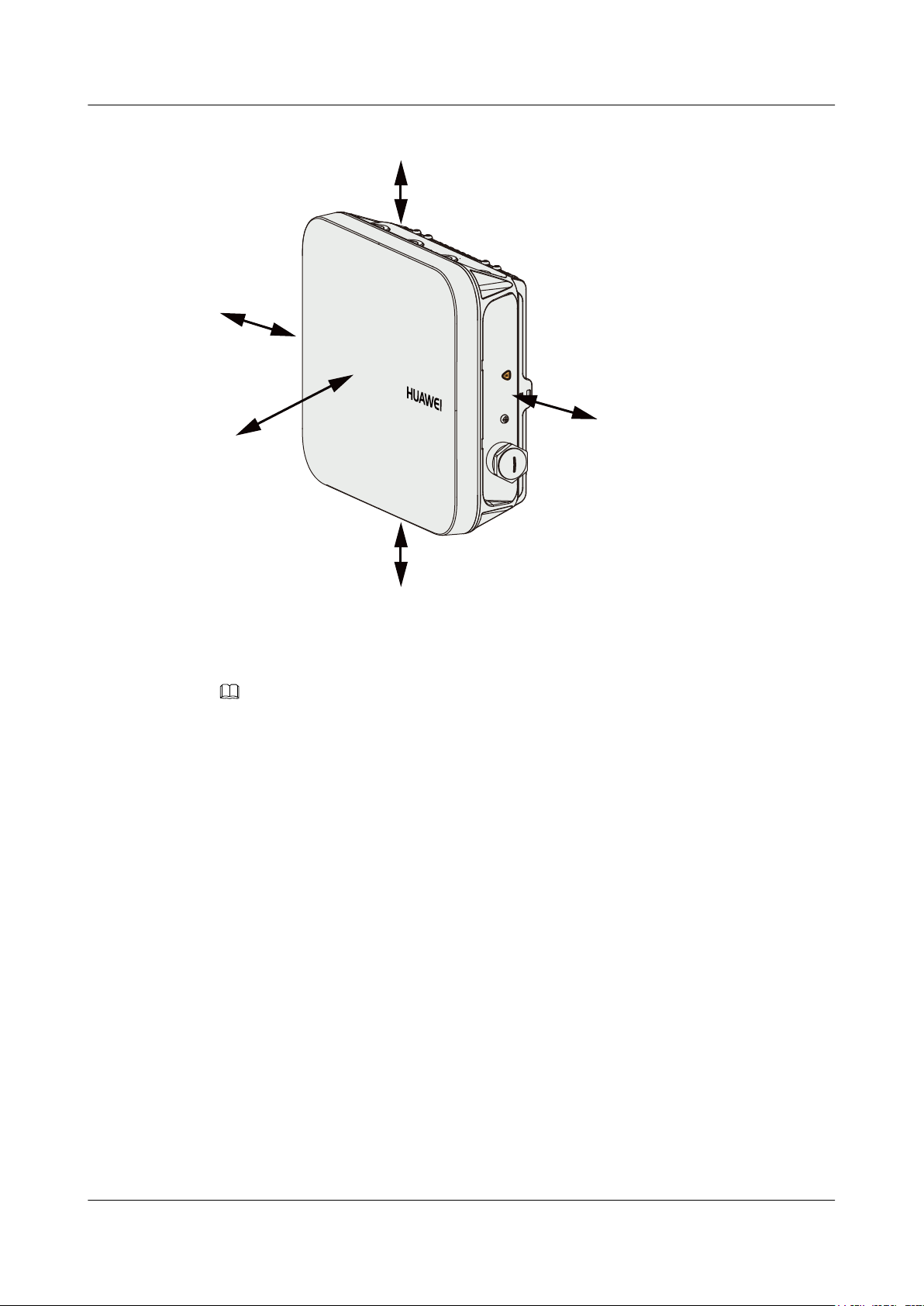
The AP8030DN and AP8130DN have the same space requirements. Figure 2-4 shows space
requirements for installing an AP8130DN.
Issue 03 (2015-05-18) Huawei Proprietary and Confidential
Copyright © Huawei Technologies Co., Ltd.
15
'HIDXOW
≥500
≥1000
≥500
≥200
≥200
Huawei AP8030DN & AP8130DN
Hardware Installation and Maintenance Guide
Figure 2-4 Space requirements for installing an AP8130DN (unit: mm)
2 AP Installation
2.5 Installing the AP
NOTE
If the AP surface is covered with protective film, remove it before installation.
2.5.1 Wall Mounting
Wall mounting requires use of the mounting bracket and matching expansion bolts. The
AP8030DN installation requires use of the angle adjusting component but the AP8130DN does
not.
l Installing an AP8030DN
l Installing an AP8130DN
Installing an AP8030DN
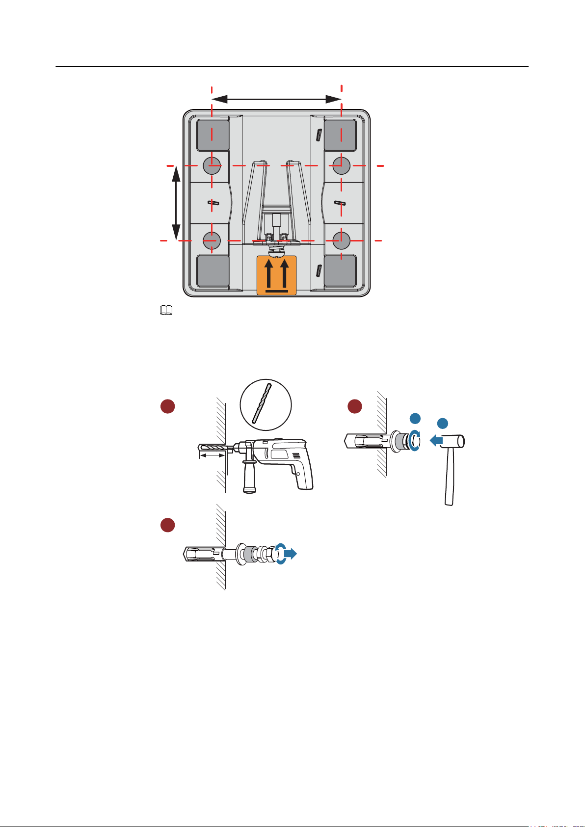
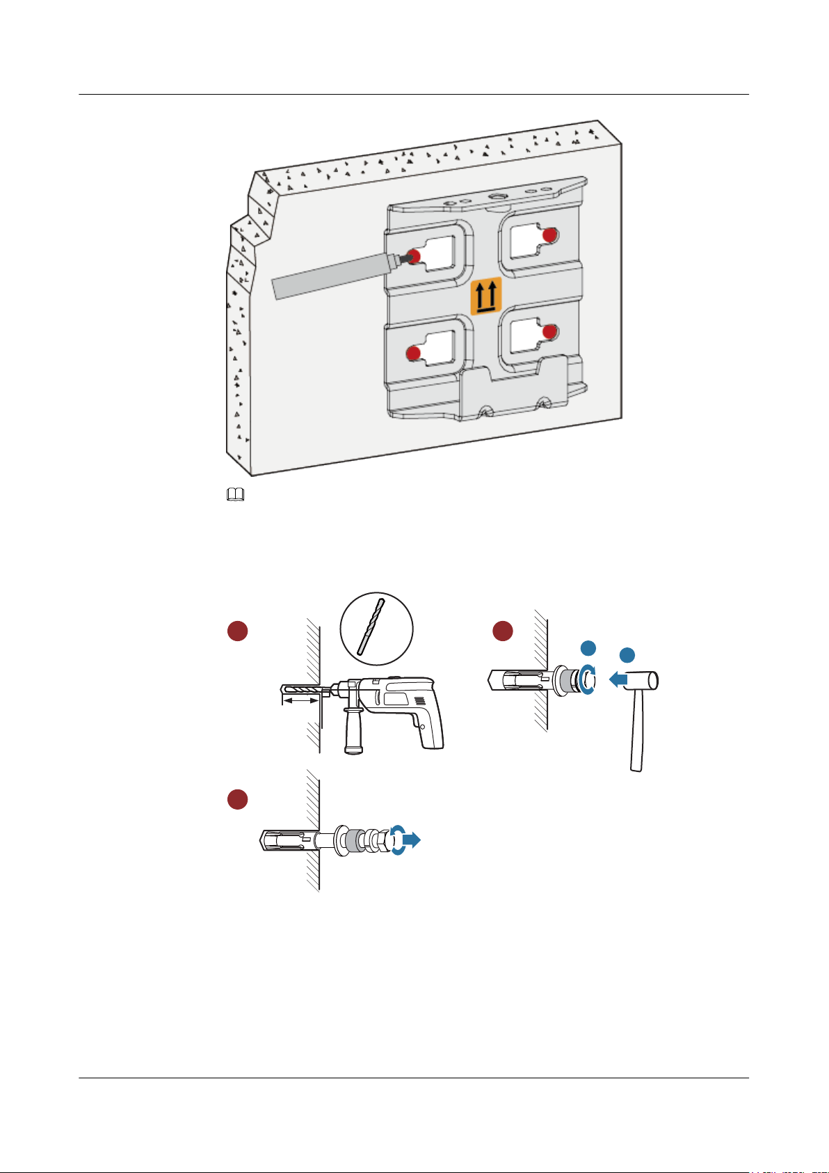
1. Fix the mounting bracket to the wall, adjust the installation position, and use the marker to
mark the drilling positions where expansion bolts are installed, as shown in the following
figure.
Issue 03 (2015-05-18) Huawei Proprietary and Confidential
Copyright © Huawei Technologies Co., Ltd.
16
64mm
37mm
90
DŽ
Ø8
35mm~40mm
a
b
1 2
3
Huawei AP8030DN & AP8130DN
Hardware Installation and Maintenance Guide
NOTE
Usually, the device can be fixed by installing two expansion bolts at diagonal positions.
2. Use an 8 mm drill bit to drill 35 mm to 40 mm deep holes in the drilling positions and
hammer the expansion bolts into the installation holes until the flat washers are completely
attached to the wall. Then, remove the nut, spring washer, and flat washer in order.
2 AP Installation
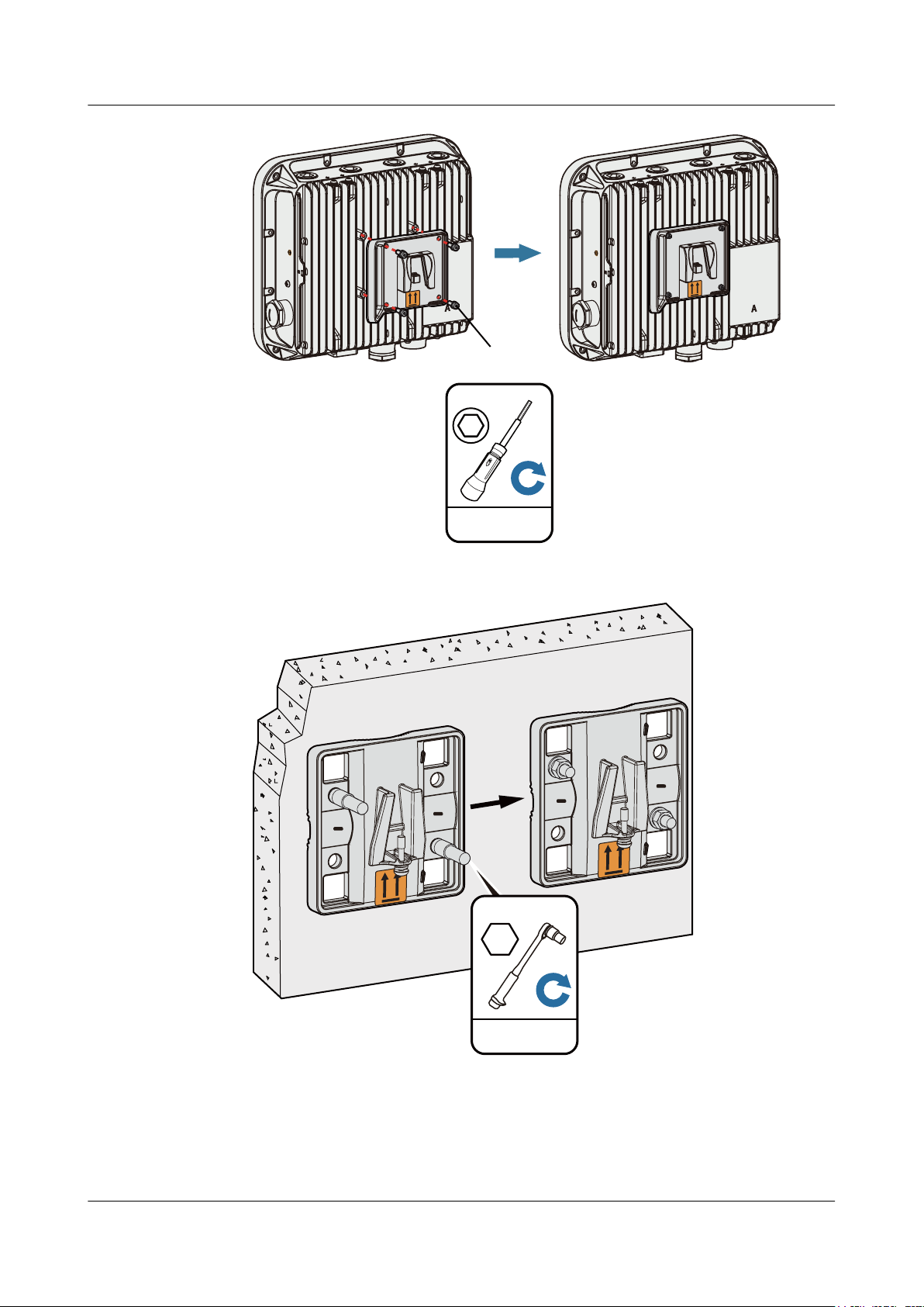
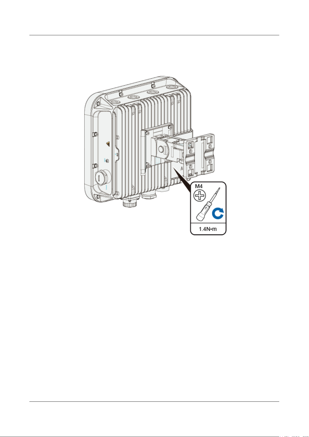
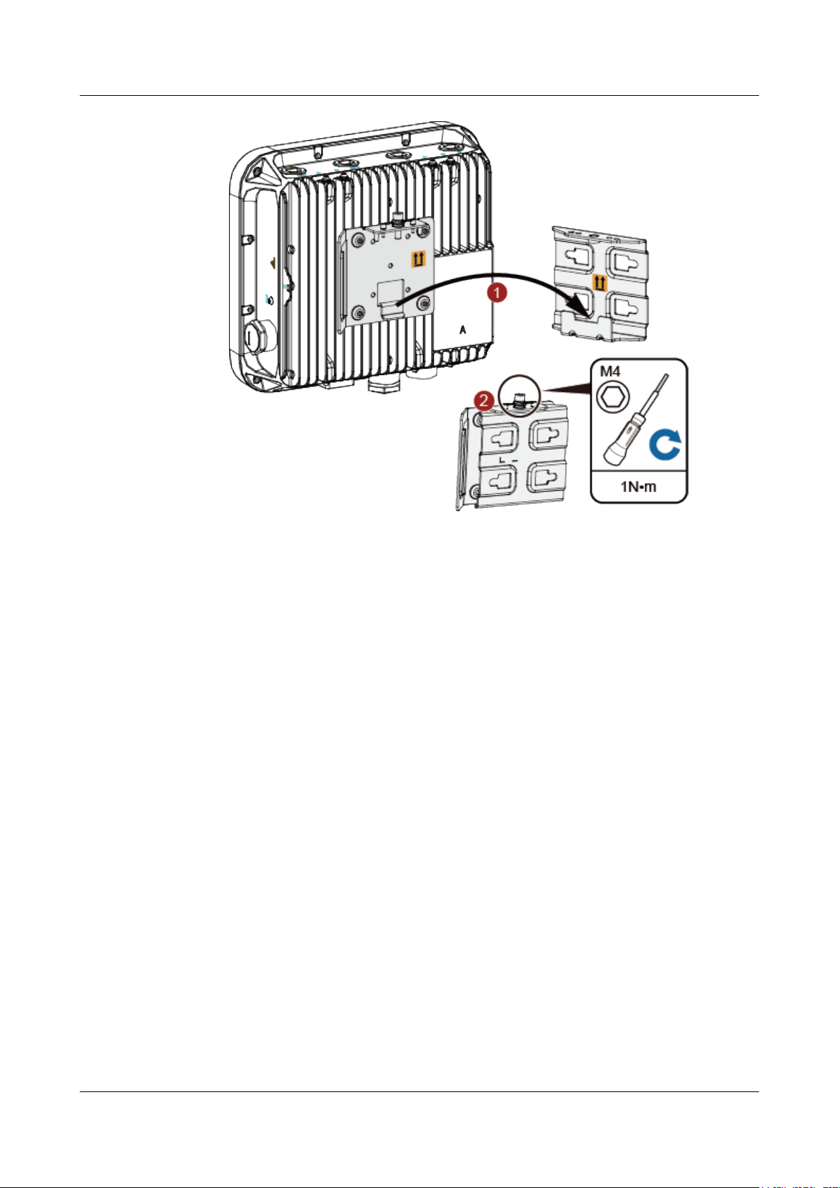
3. Use four M4x12 hexagon socket head cap screws to fasten the AP-side module of the
mounting bracket to the AP.
Issue 03 (2015-05-18) Huawei Proprietary and Confidential
Copyright © Huawei Technologies Co., Ltd.
17
**
**
*
*
'HIDXOW
**
**
*
*
'HIDXOW
Hexagon socket
head cap screw
1N•m
M4
5N•m
M6
Huawei AP8030DN & AP8130DN
Hardware Installation and Maintenance Guide
2 AP Installation
4. Hang the wall-side module of the mounting bracket on the expansion bolts and use a wrench
to fasten the flat washers, spring washers, and nuts in order.
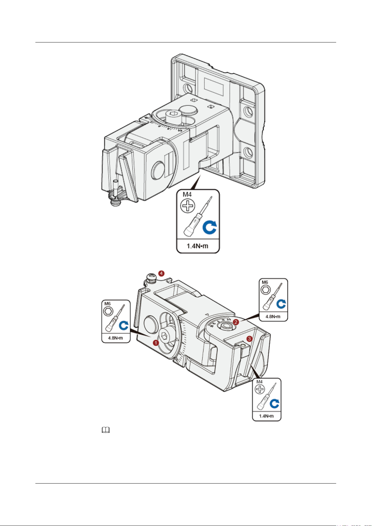
5. Hang the angle adjusting component on the mounting bracket and use a Phillips screwdriver
to tighten the screw at position 3, with a tightening torque of 1.4N*m.
Issue 03 (2015-05-18) Huawei Proprietary and Confidential
18
Copyright © Huawei Technologies Co., Ltd.
Huawei AP8030DN & AP8130DN
Hardware Installation and Maintenance Guide
2 AP Installation
6. Loosen the screws at position 1 and position 2 using an M6 hex key.
NOTE
The screw at position 4 does not need to be loosened.
l To adjust the horizontal angle of the AP, use the M6 hex key to remove the screw at
position 2, lift the angle adjusting component vertically, and adjust the angle adjusting
component horizontally.
Issue 03 (2015-05-18) Huawei Proprietary and Confidential
Copyright © Huawei Technologies Co., Ltd.
19
Huawei AP8030DN & AP8130DN
Hardware Installation and Maintenance Guide 2 AP Installation
l To adjust the vertical angle of the AP, use the M6 hex key to loosen the screw at position
1, install the AP, and adjust the vertical angle with the weight of the AP.
7. Hang the AP with the AP-side mounting bracket module to the wall-side mounting bracket
module and tighten the screws to secure the AP.
Installing an AP8130DN
1. Fix the mounting bracket to the wall, adjust the installation position, and use the marker to
mark the drilling positions where expansion bolts are installed, as shown in the following
figure.
Issue 03 (2015-05-18) Huawei Proprietary and Confidential
Copyright © Huawei Technologies Co., Ltd.
20
90
DŽ
Ø8
35mm~40mm
a
b
1 2
3
Huawei AP8030DN & AP8130DN
Hardware Installation and Maintenance Guide
2 AP Installation
NOTE
Usually, the device can be fixed by installing two expansion bolts at diagonal positions.
2. Use an 8 mm drill bit to drill 35 mm to 40 mm deep holes in the drilling positions and
hammer the expansion bolts into the installation holes until the flat washers are completely
attached to the wall. Then, remove the nut, spring washer, and flat washer in order.
Issue 03 (2015-05-18) Huawei Proprietary and Confidential
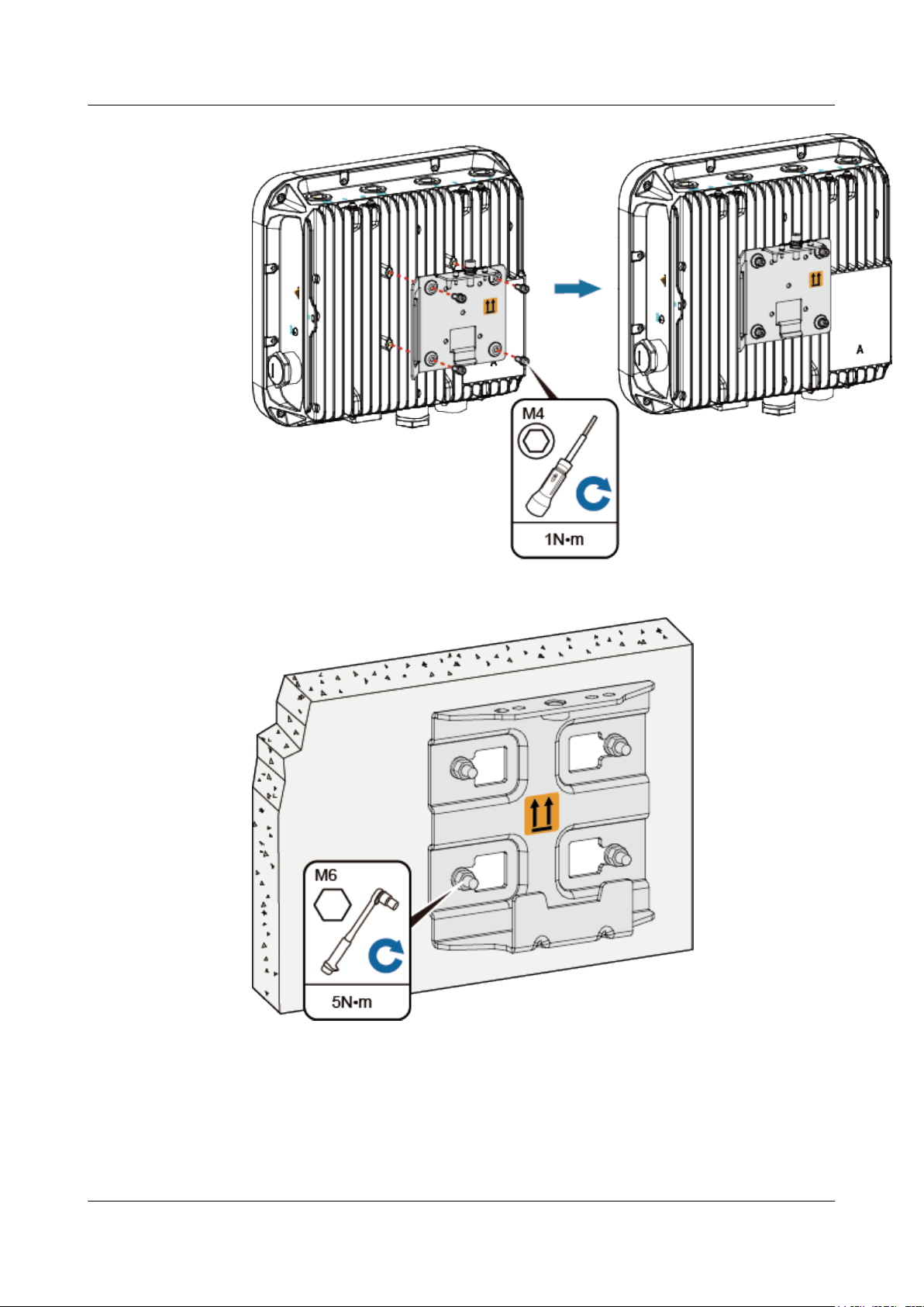
3. Use four M4x12 hexagon socket head cap screws to fasten the AP-side module of the
mounting bracket to the AP.
Copyright © Huawei Technologies Co., Ltd.
21
Huawei AP8030DN & AP8130DN
Hardware Installation and Maintenance Guide
2 AP Installation
4. Hang the wall-side module of the mounting bracket on the expansion bolts and use a wrench
to fasten the flat washers, spring washers, and nuts in order.
5. Hang the AP with the AP-side mounting bracket module to the wall-side mounting bracket
module and tighten the screws to secure the AP.
Issue 03 (2015-05-18) Huawei Proprietary and Confidential
Copyright © Huawei Technologies Co., Ltd.
22
Huawei AP8030DN & AP8130DN
Hardware Installation and Maintenance Guide
2 AP Installation
2.5.2 Pole Mounting
An outdoor AP must be installed on a pole with a diameter of 48 mm to 114 mm and the thickness
must be at least 2.5 mm. The AP8030DN installation requires use of the angle adjusting
component but the AP8130DN does not.
l Installing an AP8030DN
l Installing an AP8130DN
Installing an AP8030DN
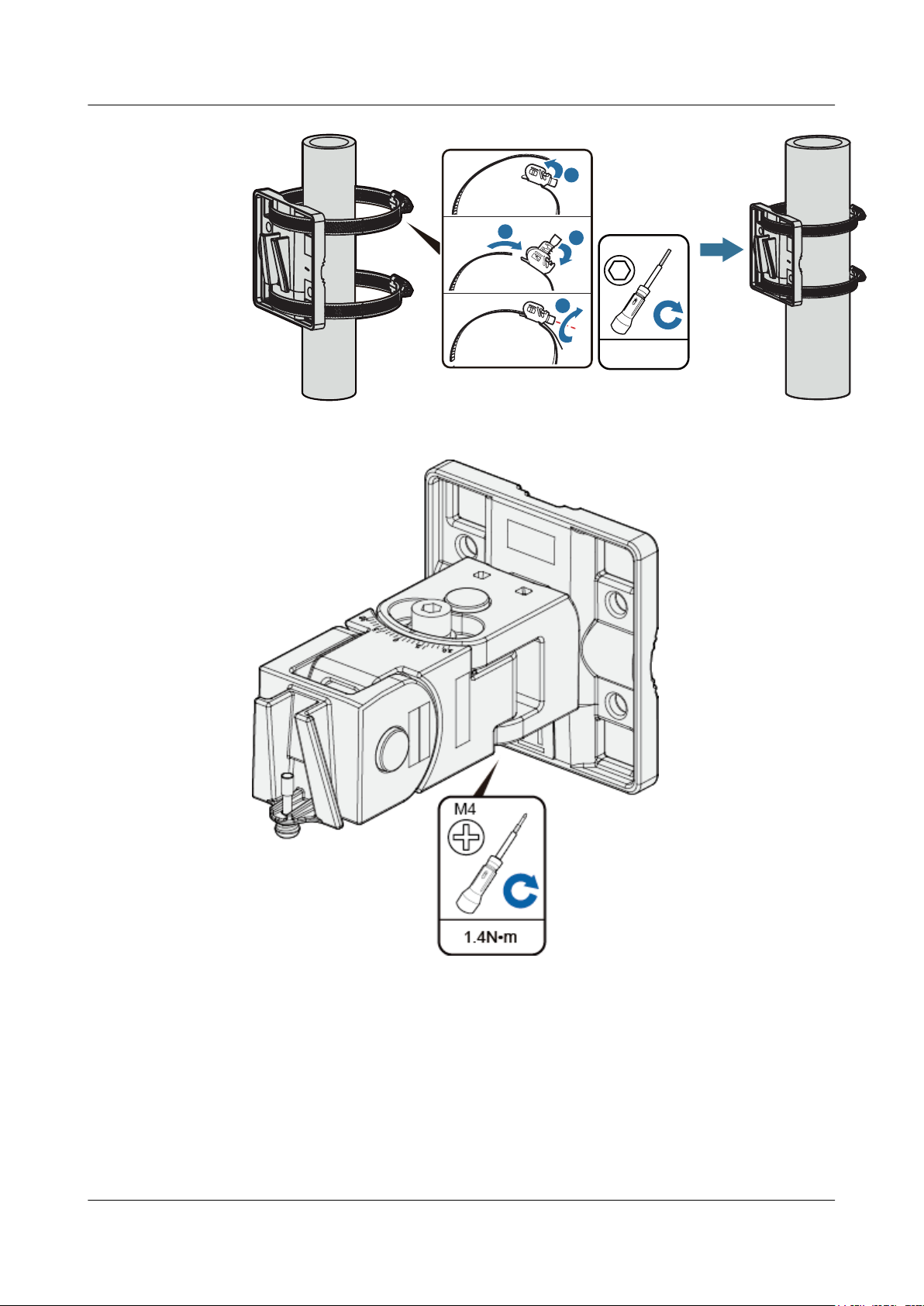
1. Determine the AP installation position and attach the mounting bracket on the pole using
the hose clamp.
a. Use the M6 hex torque screwdriver to loosen screws on the hose clamp and lift the
lid.
b. Slide the hose clamp through the hole of the mounting bracket, attach it to the pole,
and close the hose clamp.
c. Close the lid.
d. Use the hex torque screwdriver to tighten the screws with a torque of 5 N•m.
Issue 03 (2015-05-18) Huawei Proprietary and Confidential
Copyright © Huawei Technologies Co., Ltd.
23
5N•m
M6
a
b
c
d
Huawei AP8030DN & AP8130DN
Hardware Installation and Maintenance Guide
2. Hang the angle adjusting component on the mounting bracket and use a Phillips screwdriver
to tighten the screw at position 3, with a tightening torque of 1.4N•m.
2 AP Installation
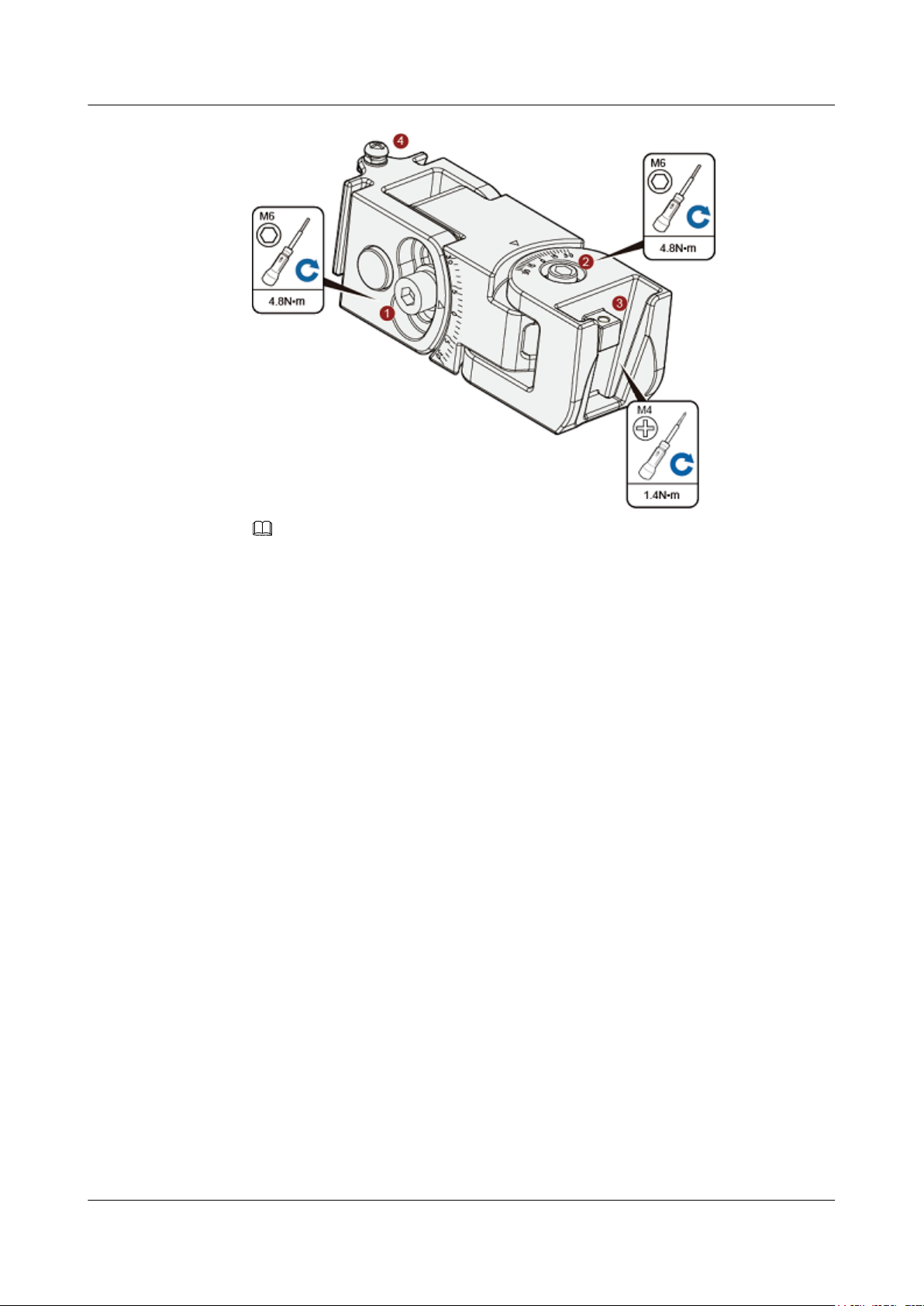
3. Loosen the screws at position 1 and position 2 using an M6 hex key.
Issue 03 (2015-05-18) Huawei Proprietary and Confidential
Copyright © Huawei Technologies Co., Ltd.
24
Huawei AP8030DN & AP8130DN
Hardware Installation and Maintenance Guide 2 AP Installation
NOTE
The screw at position 4 does not need to be loosened.
l To adjust the horizontal angle of the AP, use the M6 hex key to remove the screw at
position 2, lift the angle adjusting component vertically, and adjust the angle adjusting
component horizontally.
l To adjust the vertical angle of the AP, use the M6 hex key to loosen the screw at position
1, install the AP, and adjust the vertical angle with the weight of the AP.
4. Hang the AP with the AP-side mounting bracket module to the wall-side mounting bracket
module and tighten the screws to secure the AP.
Issue 03 (2015-05-18) Huawei Proprietary and Confidential
Copyright © Huawei Technologies Co., Ltd.
25

Huawei AP8030DN & AP8130DN
Hardware Installation and Maintenance Guide 2 AP Installation
Installing an AP8130DN
Mounting an AP on a vertical pole
1. Determine the AP installation position and attach the mounting bracket on the pole using
the hose clamp.
a. Use the M6 hex torque screwdriver to loosen screws on the hose clamp and lift the
lid.
b. Slide the hose clamp through the hole of the mounting bracket, attach it to the pole,
and close the hose clamp.
c. Close the lid.
d. Use the hex torque screwdriver to tighten the screws with a torque of 5 N•m.
Issue 03 (2015-05-18) Huawei Proprietary and Confidential
Copyright © Huawei Technologies Co., Ltd.
26

Huawei AP8030DN & AP8130DN
Hardware Installation and Maintenance Guide
2 AP Installation
2. Hang the AP with the AP-side mounting bracket module to the wall-side mounting bracket
module and tighten the screws to secure the AP.
Mounting an AP on a horizontal pole
The procedure for installing the AP against a horizontal pole is similar to the procedure for
installing the AP against a vertical pole.
Issue 03 (2015-05-18) Huawei Proprietary and Confidential
Copyright © Huawei Technologies Co., Ltd.
27

Feed line Feed line Feed line Feed line
Feed line Feed line
Optical fiber Network cable
Huawei AP8030DN & AP8130DN
Hardware Installation and Maintenance Guide
2.6 Connecting Cables
Figure 2-5 AP8130DN external cable arrangement
2 AP Installation
2.6.1 Connecting RF Cables
Issue 03 (2015-05-18) Huawei Proprietary and Confidential
Copyright © Huawei Technologies Co., Ltd.
28

Huawei AP8030DN & AP8130DN
Hardware Installation and Maintenance Guide 2 AP Installation
RF cable deployment requirements
l It is recommended that you connect a 50 ohm RF load to an idle antenna interface and wrap
the RF load with insulation tape and waterproof tape. Huawei offers 50 ohm RF loads for
you to purchase.
l Wrap the RF cable using one-layer PVC insulation tape, three-layer waterproof adhesive
tape, and then three-layer PVC insulation tape.
l Before wrapping the waterproof tape, stretch the tape evenly until the tape turns 1/2 as wide
as before. Wrap each layer of tape tightly and ensure that each layer covers more than 50%
of the layer below it.
l Wrap the three-layer tape from bottom to top, from top to bottom, and then from bottom
to top.
l Bend radius requirements: RG-8U RF cable: > 150 mm; 1/2" RF cable: > 50 mm; 7/8" RF
cable: > 250 mm. One inch equals to 25.4 mm.
NOTICE
Tighten the nut of the AP's RF connector with a maximum torque of 1.2 N•m.
RF cable connections
1. Antenna interfaces of the AP provides a 5 KA surge protection capability. Generally, no
additional surge protective device needs to be installed, and the RF cables are directly
connected to the antenna interfaces.
2. If a higher surge protection capability is required, the customer can purchase a surge
protective device. When installing the surge protective device, ensure that it is connected
to a ground cable.
Issue 03 (2015-05-18) Huawei Proprietary and Confidential
Copyright © Huawei Technologies Co., Ltd.
29

Huawei AP8030DN & AP8130DN
Hardware Installation and Maintenance Guide
2.6.2 Connecting Optical Fibers and Network Cables
Connecting optical fibers
2 AP Installation
NOTE
The device can transmit upstream data over optical fibers. The optical fiber is connected to the device using
fiber connectors (purchased independently).
The following figure shows components of an optical fiber connector.
Figure 2-6 Components of an optical fiber connector
(1) Optical fiber
(2) Support (3) Rubber ring (4) External connector shell
1. Select an optical cable of a proper length based on onsite cabling.
2. Remove the waterproof block from the rubber ring of the connector, as shown in the
following figure.
Issue 03 (2015-05-18) Huawei Proprietary and Confidential
Copyright © Huawei Technologies Co., Ltd.
30

Huawei AP8030DN & AP8130DN
Hardware Installation and Maintenance Guide
Figure 2-7 Removing the waterproof block
3. Assemble the connector on the optical fiber.
a. Assemble the external connector shell and support, as shown in the following figure.
2 AP Installation
Figure 2-8 Assembling the connector (1)
b. Put the rubber ring on the optical fiber and insert it into the support in compliance
with the direction indicated on the ring, as shown in the following figure.
Figure 2-9 Assembling the connector (2)
NOTE
Ensure that the arrow on the rubber ring points to the support.
4. Remove the sealing cover of the optical fiber port on the device and insert the optical fiber
into the port. Turn the support to find the correct optical fiber installation slot and push the
support forward (together with the rubber ring) until the optical fiber is installed to the
Issue 03 (2015-05-18) Huawei Proprietary and Confidential
Copyright © Huawei Technologies Co., Ltd.
31

Huawei AP8030DN & AP8130DN
Hardware Installation and Maintenance Guide 2 AP Installation
correct position. Rotate the external connector shell clockwise until the red ring is not
visible, as shown in the following figure.
Figure 2-10 Connecting optical fibers
NOTICE
l Connect the optical fiber correctly; otherwise, the optical fiber may be damaged.
l Bundle the optical fibers with binding tapes every 1 m.
Connecting network cables
1. Use a shielded straight-through cable. Cut the cable into a proper length based on the
distance between the AP and the PSE device, strip the cables on both ends, and crimp the
wires into RJ45 connectors.
2. Make a network cable onsite according to pin assignment in Table 2-3. Otherwise, the
communication quality is affected even if devices can be connected.
Table 2-3 Pin assignment
X1 Pin Wire Color X2 Pin
1 White and orange 1
2 Orange 2
3 White and green 3
4 Blue 4
5 White and blue 5
6 Green 6
Issue 03 (2015-05-18) Huawei Proprietary and Confidential
Copyright © Huawei Technologies Co., Ltd.
32

b
c
d
a
d
c
b
a
Huawei AP8030DN & AP8130DN
Hardware Installation and Maintenance Guide
X1 Pin Wire Color X2 Pin
7 White and brown 7
8 Brown 8
NOTE
Actually, APs use shielded straight-through network cables, which are connected in the same way
as unshielded network cables.
3. Put the network cable through waterproof PG connectors. Connect the RJ45 connector to
the ETH/PoE interface on the AP and secure the waterproof PG connector. See figures b,
c, and d.
Figure 2-11 Connecting network cables
2 AP Installation
NOTE
l The network cables used are shielded straight-through cables.
l Ensure that the RJ45 connector is correctly connected to the AP. Otherwise, the network cable
may be damaged. Before removing the network cable from the AP, remove the waterproof PG
connector first and then remove the RJ45 connector.
l The cable cannot exceed 100 meters.
2.6.3 Connecting Ground Cables
Grounding is a key step in device installation. The ground cable of a device must be correctly
connected to protect the device from lightning, electromagnetic interference, and electrostatic
charges. Outdoor APs support built-in surge protection on all interfaces, but the surge protection
works only when the outdoor APs are grounded.
Issue 03 (2015-05-18) Huawei Proprietary and Confidential
Copyright © Huawei Technologies Co., Ltd.
33

Huawei AP8030DN & AP8130DN
Hardware Installation and Maintenance Guide
Requirements for laying out ground cables
l The ground cables must be connected to a group of ground bars.
l The bend radius of the ground cables must be larger than or equal to five times the cable
diameter.
l The ground cables must be buried underground or routed indoors and cannot be led into
the equipment room aerially.
l Both ends of the external conductor of the coaxial cable and those of the shield layer of the
shielded cable should have good electric contact with the metal shell of the equipment they
connect to.
l Ground cables must be separated from signal cables to reduce interference between them.
l Do not add any switch or fuse on the ground cable.
l Do not use another device for an electrical connection with the ground cable.
l All metal components in the shell must be securely connected to the ground terminal.
Ground cable connections
2 AP Installation
1. Cut the ground cable into a proper length and use the M4 OT terminal to connect to the
AP. The OT terminal used to connect to the ground terminal depends on site requirements.
NOTE
To tighten the screws with a torque on the ground bar,
l M4: 1.4N•m.
l M6: 4.8N•m.
l M8: 12N•m.
2. The equipment functions properly when the ground resistance is less than 10 ohms.
Grounding shielded network cables
Using shielded network cables can improve surge protection performance of the AP. To connect
the cable, cut the shield layer open, connect the cable to the ground clip, and wrap the cable with
waterproof and ESD tapes.
Issue 03 (2015-05-18) Huawei Proprietary and Confidential
Copyright © Huawei Technologies Co., Ltd.
34

Huawei AP8030DN & AP8130DN
Hardware Installation and Maintenance Guide
1. Determine the position for installing the ground clip on the cable based on the actual cable
route.
2. Use a utility knife to strip the sheath off the network cable for about 32 mm (1.26in.) to
expose the shield layer.
NOTICE
Do not damage the shield layer when stripping the sheath off the cable.
2 AP Installation
3. Install the ground clip on the shield layer of the cable, and then use a screwdriver to tighten
the screws on the ground clip.
(1) Ground cable
4. Wrap three layers of waterproof tape and three layers of polyvinyl chloride (PVC) insulation
tape at the ground clip.
(2) Ground clip (3) Network cable
Issue 03 (2015-05-18) Huawei Proprietary and Confidential
Copyright © Huawei Technologies Co., Ltd.
35

Huawei AP8030DN & AP8130DN
Hardware Installation and Maintenance Guide
NOTICE
l Wrap the tape around the clip from bottom up, then from top down, and finally from
bottom up. Do not cut the tape until all the three layers of the tape are already wrapped.
When wrapping tape, be sure that each layer of tape overlaps more than 50% of the
preceding layer.
l The degree between the ground cable and the network cable cable is not greater than
15°. When the network cable is routed vertically, the ground cable must be routed
downwards.
2 AP Installation
(1) Waterproof tape (2) PVC insulation
tape
5. Connect the ground cable to an external ground bar.
(3) Network cable (4) Ground cable
2.6.4 Installing Outdoor Antennas
Two types of outdoor antennas are available: directional outdoor antenna and omnidirectional
outdoor antenna. Omnidirectional antennas can be directly installed on APs.
Installing a directional outdoor antenna against a pole
Pay attention to the following points when installing a directional antenna:
1. An outdoor antenna must be installed on a pole with a diameter of 30 mm to 50 mm and
the thickness must be at least 2.5 mm. A 50 mm diameter pole made of round steel is usually
used.
2. Weld the lightning rod on the top of the antenna pole.
3. Install the antenna pole on a parapet or concrete bed on the roof of the building.
4. Use a 40 mm x 4 mm flat steel to connect the antenna pole to an earth mat.
5. Secure the directional outdoor antenna on the pole with an antenna support.
6. Keep the pole vertical to the ground during the installation.
Issue 03 (2015-05-18) Huawei Proprietary and Confidential
Copyright © Huawei Technologies Co., Ltd.
36

Outdoor
directional
antenna
Parapet
Lightning rod
Antenna support
Pole
Flat steel
Connected to
the earth mat
Parapet height > 1.2 m
Parapet height < 1.2 m
No parapet
Steel wire
Concrete
bed
Huawei AP8030DN & AP8130DN
Hardware Installation and Maintenance Guide 2 AP Installation
See Figure 2-12 below for how a directional outdoor antenna is installed on a pole.
l If the roof of the building is surrounded by parapets of no less than 1.2 m high, fix the pole
on a parapet with expansion screws, and then fix the directional outdoor antenna on the
pole with an antenna support.
l If the roof of the building is surrounded by parapets of less than 1.2 m high, fix the pole on
a parapet and on the ground with expansion screws, and then fix the directional outdoor
antenna on the pole with an antenna support.
l If there is no parapet around the roof, fix the pole on the ground or a concrete bed with
expansion screws and steel wires, and then fix the directional outdoor antenna on the pole
with an antenna support.
Figure 2-12 Installing a directional outdoor antenna against a pole
Figure 2-13 shows outdoor AP installation scenarios.
Issue 03 (2015-05-18) Huawei Proprietary and Confidential
Copyright © Huawei Technologies Co., Ltd.
37

Huawei AP8030DN & AP8130DN
Hardware Installation and Maintenance Guide 2 AP Installation
Figure 2-13 Outdoor AP installation scenarios
Installing an omnidirectional outdoor antenna against a pole
Pay attention to the following points when installing an omnidirectional antenna:
1. An outdoor antenna must be installed on a pole with a diameter of 30 mm to 50 mm and
the thickness must be at least 2.5 mm. A 50 mm diameter pole made of round steel is usually
used.
2. The top of pole must be aligned with the hose clamp at the bottom of the antenna.
3. The antenna must be installed at a proper height to provide sufficient signal coverage, and
the top of the antenna must be within the 45 degrees protection angle of the lighting rod.
4. Do no weld a lightning rod directly on the antenna pole (there should not be metal subjects
within 1 m around an omnidirectional antenna). Instead, install an independent lightning
rod between two omnidirectional antenna poles. Adjust the height of the lightning rod to
ensure that the omnidirectional antennas are covered in the protection angle.
Figure 2-14 shows installation of an omnidirectional outdoor antenna.
Issue 03 (2015-05-18) Huawei Proprietary and Confidential
Copyright © Huawei Technologies Co., Ltd.
38

Protection
angle
Omnidirectional
antenna
Hose clamp
Antenna pole
Lightning rod
>1.0m
Lock hole
Security lock
Console/RSSI
Default
Huawei AP8030DN & AP8130DN
Hardware Installation and Maintenance Guide 2 AP Installation
Figure 2-14 Installing an omnidirectional outdoor antenna
2.7 Installing the Security Lock
NOTE
If antennas are installed on a metal pole such as a steel pole, you do not need to install a lightening rod, as
shown on the right in Figure 2-14.
There is a security slot on the AP. You can lock the AP to an immovable object to prevent the
AP against theft. The detailed procedures are as follows:
1. Fasten the cable of the security lock to an immovable object around.
2. Insert the security lock into the security slot and lock it.
Issue 03 (2015-05-18) Huawei Proprietary and Confidential
Copyright © Huawei Technologies Co., Ltd.
39

Huawei AP8030DN & AP8130DN
Hardware Installation and Maintenance Guide
NOTE
You need to purchase the security lock separately.
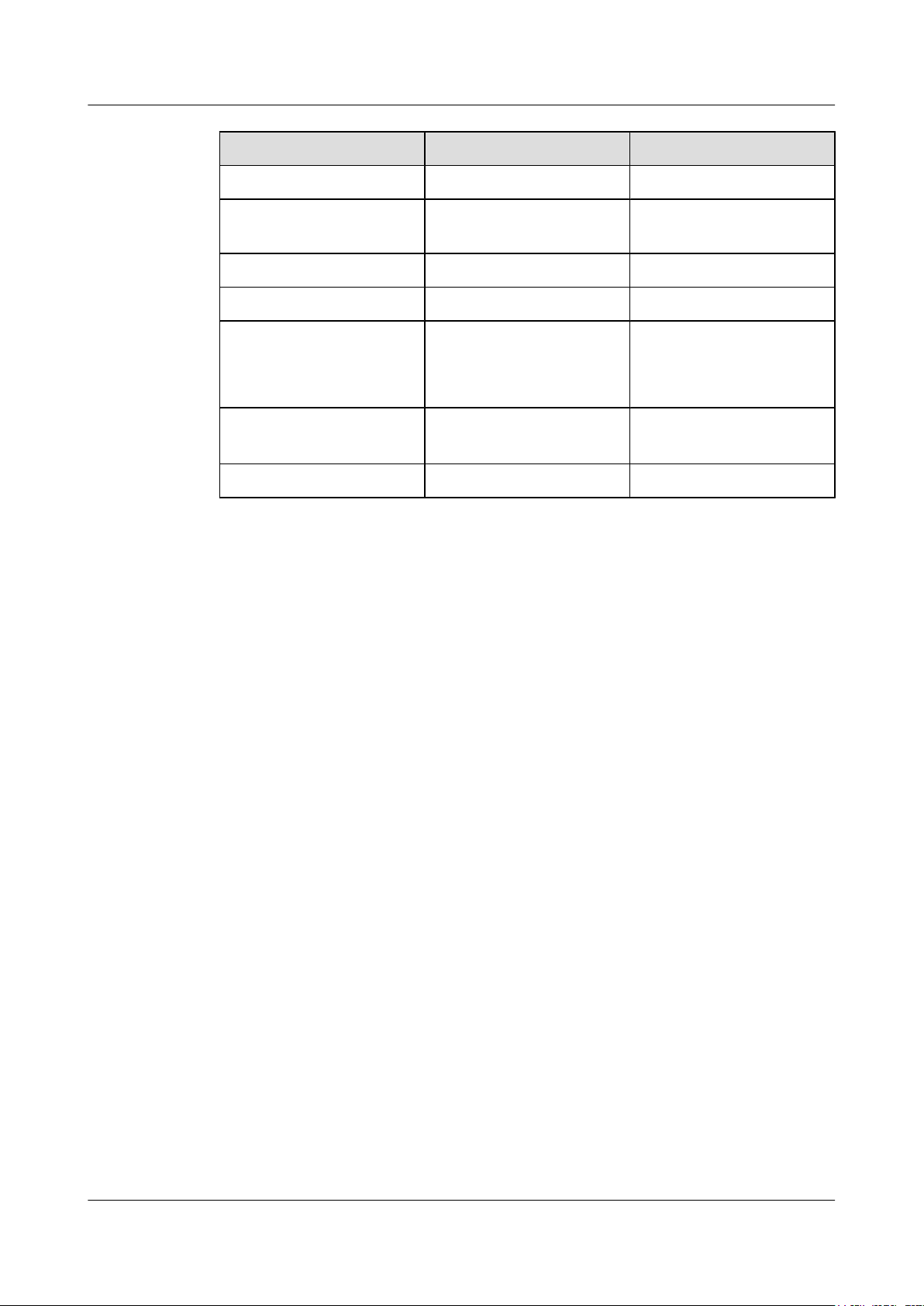
2.8 Checking the AP After Installation
Table 2-4 shows the items to be checked after AP installation is complete.
Table 2-4 AP installation checklist
No. Check Item
1 The AP is installed by strictly following the design draft. The installation
position meets space requirements, with maintenance space reserved.
2 The AP is securely installed.
3 Waterproof caps are installed on idle interfaces and securely fastened.
4 The power cables and PGND cables are intact and not spliced.
2 AP Installation
5 Terminals of the power cables and PGND cables are welded or cramped
firmly.
6 All power cables or PGND cables are not short-circuited or reversely
connected and must be intact with no damage.
7 The power cables and ground cables are separated from other cables and
bundled separately.
8 The working ground, protection ground, and surge protection ground share
the same group of ground bars.
9 Connectors of signal cables are complete, intact, and tightly connected.
The signal cables are not damaged or broken.
10 Labels on cables, feeders, or jumpers are clear and correct.
2.9 Powering on the AP
After the AP installation is complete, observe indicators on the AP to determine the system
running status. For details, see 1.2 Indicator Description.
NOTE
Do not frequently power on and off an AP.
Issue 03 (2015-05-18) Huawei Proprietary and Confidential
Copyright © Huawei Technologies Co., Ltd.
40

Huawei AP8030DN & AP8130DN
Hardware Installation and Maintenance Guide 3 Logging In to the AP
3 Logging In to the AP
About This Chapter
After an AP is powered on, you can log in to the AP using the following method:
Version Telnet server STelnet server
V200R003C00 and earlier
versions
V200R005C00 and later
versions
3.1 Logging In to the AP Through the Console Port
3.2 Logging In to the AP Using STelnet
3.3 Logging In to the AP Using Telnet
3.4 Logging In to the AP Using a Web Client
Enable Enable
Disable Enable
Issue 03 (2015-05-18) Huawei Proprietary and Confidential
Copyright © Huawei Technologies Co., Ltd.
41

Huawei AP8030DN & AP8130DN
Hardware Installation and Maintenance Guide
3 Logging In to the AP
3.1 Logging In to the AP Through the Console Port
This section describes how to log in to the AP through the console port. After logging in to the
AP, you can configure the AP using commands.
1. Connect a PC to the AP using a console cable. Connect the RJ45 connector to the console
port of the AP and the DB9 connector to the serial port of a PC.
NOTE
If your PC's operating system provides terminal simulation software (like HyperTerminal in
Windows 2000/XP), you do not need to install additional terminal simulation software. If the PC
runs on an operating system without terminal simulation software (like Windows 7), install thirdparty terminal simulation software on the PC by referring to user manual or online help.
2. Start the terminal simulation software, create a connection, select a serial port, and set
communication parameters as follows.
l Bits per second (B): 9600
l Data bits (B): 8
l Parity (P): None
l Stop bits (S): 1
l Flow control (F): None
3. Press Enter until the command line prompt of the user view, such as <Enterprise AP>, is
displayed. Then, you enter the user configuration interface. You can run commands to
configure the AP. Enter a question mark (?) whenever you need help.
3.2 Logging In to the AP Using STelnet
This section describes how to log in to the AP using STelnet. After logging in to the AP, you
can configure the AP using commands.
Before logging in to the device through STelnet, complete the following tasks:
l Starting the device properly
l Preparing network cables used to connect device interfaces.
l Configuring the PC's IP address and subnet mask. The IP address must be on the network
segment 169.254.0.0/16 but cannot be 169.254.1.1. 169.254.1.100 is recommended. The
subnet mask is 255.255.0.0.
NOTE
l Ensuring that the IP address 169.254.1.1 and subnet mask 255.255.0.0 have been configured on VLANIF
1 of the device before the delivery, and GE0/0/0 has been added to VLAN 1 by default.
l Before the device is delivered, the STelnet service has been configured on the device. The STelnet interface
number is 22, and the default user name and password are respectively admin and admin@huawei.com.
Use the SSH client software to log in to the device through STelnet from a terminal. The
third-party software PuTTY is used as an example here.
1. After the device is powered on, connect the PC's network interface to GE0/0/0 of the device
using network cables.
Issue 03 (2015-05-18) Huawei Proprietary and Confidential
Copyright © Huawei Technologies Co., Ltd.
42

Huawei AP8030DN & AP8130DN
Hardware Installation and Maintenance Guide
NOTE
Ping 169.254.1.1 from the PC to check whether the device can be pinged successfully. If the ping
operation fails, check whether the PC's IP address is correct or replace the network cable.
2. Use the PuTTY software to log in to the device, enter the device IP address, and select the
SSH protocol type.
Figure 3-1 PuTTY Configuration page
3 Logging In to the AP
3. Click Open. Enter the user name and password at the prompt, and press Enter. You have
logged in to the device. (The following information is only for reference.)
login as: admin
Sent username "admin"
admin@169.254.1.1's password:
<Huawei>
NOTE
It is recommended that you change the initial user name and password after login.
3.3 Logging In to the AP Using Telnet
Issue 03 (2015-05-18) Huawei Proprietary and Confidential
Copyright © Huawei Technologies Co., Ltd.
43

Huawei AP8030DN & AP8130DN
Hardware Installation and Maintenance Guide
This section describes how to log in to the AP using Telnet. After logging in to the AP, you can
configure the AP using commands.
NOTE
The Telnet protocol poses a security risk, and therefore the STelnet V2 protocol is recommended.
1. Connect a PC to the ETH/PoE interface of the AP using a network cable.
2. Configure a static IP address for the PC. The IP address must be in the same network
segment as the AP's IP address. After completing the configuration, ping the AP's IP address
from the PC. If the ping operation succeeds, the connection is set up successfully. If the
ping operation fails, check whether the network cable is faulty.
NOTE
l The IP address 169.254.1.1 and subnet mask 255.255.0.0 have been configured on VLANIF 1 of the
AP before the delivery, and GE0/0/1 has been added to VLAN 1 by default.
l If the AP working in Fit AP mode is online on the AC, the DHCP server automatically assigns an IP
address to the AP. You can remotely log in to the AC on a local terminal and run the following
command to check the AP's IP address:
l For V200R005C30 and earlier versions: display ap-run-info id ap-id
l For V200R006C00: display ap run-info ap-name ap-name
3. Enter the command line interface on the PC. For example, in Windows XP, choose Start
> Run and enter cmd in the displayed dialog box.
3 Logging In to the AP
4. Use Telnet to log in to the AP.
5. Enter the default user name and password. The default user name is admin, and the default
password is admin@huawei.com. If the user view is displayed, you have logged in
successfully. You are advised to change the user name and password on your first login.
NOTE
You can run the quit command to exit from the Telnet window. When the system fails to exit from the
Telnet window:
l If you logged in to the AP from an AC or a switch, press Ctrl+T to return to the AC or switch view.
This operation does not affect AP services.
l If you logged in to the AP from a PC, directly close the Telnet window. This operation does not affect
AP services.
3.4 Logging In to the AP Using a Web Client
Pre-configuration Tasks
Before configuring users to log in to the AP using HTTP, complete the following task:
Configure reachable routes between the terminal and the AP.
Issue 03 (2015-05-18) Huawei Proprietary and Confidential
Copyright © Huawei Technologies Co., Ltd.
44

Huawei AP8030DN & AP8130DN
Hardware Installation and Maintenance Guide 3 Logging In to the AP
NOTE
l The web management system is enabled on the AP before delivery. The default IP address of the web
management system is 169.254.1.1 and the mask is 255.255.0.0. The web management system provides
a default user account, with the user name admin and password admin@huawei.com. You are advised
to change the user name and password on your first login. Assign your PC an IP address on the same
network segment as the default IP address of the web management system, and connect the PC to the
GE interface. Start the web browser on the PC and visit http://169.254.1.1 to log in to the web
management system.
l You can only log in to the FAT AP using the web platform.
Procedure
Step 1 Open a web browser on a PC, and enter the management address in the format of http://
169.254.1.1 in the address bar. Ensure that the PC and AC can communicate with each other.
Then press Enter. Set the language, user name, and password. The HTTPS login URL is
displayed in the address box indicating that the system has gone to the HTTPS login page.
NOTE
You can also enter https://IP address in the address box to log in to the AP using HTTPS. HTTPS ensures
security of login information during login and security of data exchanged during subsequent operations.
Step 2 Click Login or press Enter. The web system home page is displayed. You can manage and
maintain the equipment. For details, see the Huawei Wireless Access Points Web-based
Configuration.
----End
Issue 03 (2015-05-18) Huawei Proprietary and Confidential
Copyright © Huawei Technologies Co., Ltd.
45

Huawei AP8030DN & AP8130DN
Hardware Installation and Maintenance Guide 4 Hardware Failures
4 Hardware Failures
About This Chapter
This section describes common methods for troubleshooting typical hardware faults.
4.1 An device Fails to Be Powered On
4.2 An Optical Interface Cannot Turn Up
Issue 03 (2015-05-18) Huawei Proprietary and Confidential
Copyright © Huawei Technologies Co., Ltd.
46

Huawei AP8030DN & AP8130DN
Hardware Installation and Maintenance Guide
4.1 An device Fails to Be Powered On
Fault Description
The SYS indicator of a device is off.
Possible Causes
l The power sourcing equipment does not support the PoE function or is faulty.
l The power sourcing equipment is incorrectly configured (the PoE function is disabled or
the power-off time range is improperly set).
l The line is faulty (the network cable or distribution frame is damaged).
l The AP is faulty.
Troubleshooting Procedure
1. Check whether the power sourcing equipment supports PoE or is faulty.
2. Check whether the configuration on the power sourcing equipment causes PoE power
supply errors, such as the PoE function is disabled or the power-off time range is incorrectly
set.
3. Check whether the network cable or distribution frame is faulty.
4. If the device still cannot be powered on, the device itself is faulty. Contact Huawei technical
support engineers or Huawei agent and ask them to replace the device.
4 Hardware Failures
4.2 An Optical Interface Cannot Turn Up
Fault Description
After an optical interface is connected to a remote device through an optical fiber, its LINK
indicator is off.
Possible Causes
l The optical fiber is faulty.
l The optical module on the optical interface cannot meet the requirements.
Troubleshooting Procedure
1. Replace the optical fiber and optical module and check whether the optical interface can
turn Up. Ensure that the optical module meets the following requirements.
2. Determine optical module attributes.
l The optical module has passed Huawei certification.
l The transmission speed of the optical module is the same as the interface speed.
l The wavelength of the optical module is the same as that of the remote optical module.
l The transmission distance of the optical module is suitable for the actual distance
between the two devices.
Issue 03 (2015-05-18) Huawei Proprietary and Confidential
Copyright © Huawei Technologies Co., Ltd.
47

Huawei AP8030DN & AP8130DN
Hardware Installation and Maintenance Guide 4 Hardware Failures
NOTE
l The transmission distance of an optical module is 10 km, 15 km, 20 km, 40 km, or 80 km.
The optical modules with a longer transmission distance have a higher transmit power. If an
optical module with a long transmission distance is used for short-distance transmission, the
optical interface cannot turn Up because the transmit power is too high. The high transmit
power may even burn the receiver of the remote optical module. To reduce the transmit power
in this situation, use an optical attenuator between the optical module and optical fiber.
l Optical modules with different speeds are available, for example, 155 Mbit/s, 622 Mbit/s,
and 1.25 Gbit/s. It is recommended that you use an optical module with the same speed as
the optical interface to ensure efficient optical transmission.
3. If the interface remains Down, contact Huawei technical support.
Issue 03 (2015-05-18) Huawei Proprietary and Confidential
Copyright © Huawei Technologies Co., Ltd.
48

Huawei AP8030DN & AP8130DN
Hardware Installation and Maintenance Guide 5 Appendix
5 Appendix
About This Chapter
5.1 On-site Cable Assembly and Installation
5.2 Environmental Requirements for Device Operation
5.3 Equipment Grounding Specifications
5.4 Engineering Labels for Cables
5.5 Guide to Using Optical Modules
5.6 Fault Tag
Issue 03 (2015-05-18) Huawei Proprietary and Confidential
Copyright © Huawei Technologies Co., Ltd.
49

Huawei AP8030DN & AP8130DN
Hardware Installation and Maintenance Guide
5.1 On-site Cable Assembly and Installation
5.1.1 Cable Assembly Precautions
Checking the Appearance of Cables
l If the cable jacket or insulation is visibly dirty, clean it before assembly.
l If the jacket or insulation of a cable has visible damage, irreparable scuffing, or other
defects, do not use the cable.
l If the shield layer of a cable is damaged, do not use the cable.
l If the cable jacket or insulation cracks after the cable is bent or twisted, discard this cable
and check whether other cables have the same problem. If other cables have the same
problem, replace these cables.
5 Appendix
Checking the Appearance of Connectors
l Do not use connectors with visible defects, damage, rust or scuffing.
l Do not use connectors if their shells or pins have exposed part or uneven plating, or their
pins are lost, broken, or bent.
l Do not use connectors that have dirt on their pins or in their jacks or if there are conductors
between pins or between pins and the shell.
Precautions for Assembly
l Use dedicated tools or tools delivered by Huawei and follow the methods given here during
assembly.
l Hold terminals of cables instead of pulling the cables when installing or removing cable
components.
l Take the following precautions when cutting or stripping cables:
– Make cables slightly longer than necessary.
– Coil cables longer than 2 m (6.56 ft) after cutting. Bind and fasten the coils using
bundling ropes. The inner diameters of the coils should be larger than 20 times the outer
diameters of the cables.
– When stripping the jackets of cables, avoid damaging the shield layers (braid or
aluminum foil), insulation, core conductors, and other jackets that do not need to be
stripped.
– After assembling cables, cut all visible cross sections of jackets to ensure that the cross
sections are arranged neatly.
– Do not touch the core conductors of cables with your hands. Terminate exposed
conductors in a timely way after stripping off insulation so that the surface of the
conductors does not become oxidized.
l Take the following precautions when crimping and connecting cables or connectors:
Issue 03 (2015-05-18) Huawei Proprietary and Confidential
Copyright © Huawei Technologies Co., Ltd.
50

Huawei AP8030DN & AP8130DN
Hardware Installation and Maintenance Guide
– The terminals and conductors should be connected tightly after they are crimped. They
should not be moved or turned.
– Cut all the exposed copper wires.
– Try to avoid a second crimping of sleeves.
– Keep all the conductors clean and aligned.
NOTE
The connectors, cables, and tools provided by different vendors may be different. The figures in this
document are only for your reference.
5.1.2 Assembling Power Cables
Assembling the OT Terminal and Power Cable
Context
Figure 5-1 shows the components of an OT terminal and a power cable.
5 Appendix
Procedure
Step 1 Based on the cross-sectional area of the cable conductor, strip a length of insulation coating C
Figure 5-1 Components of an OT terminal and a power cable
A Heat-shrinkable tubing
to expose the conductor D of length L1, as shown in Figure 5-2. The recommended values of
L1 are listed in Table 5-1.
B. Bare crimping terminal C. Insulation D. Conductor
Issue 03 (2015-05-18) Huawei Proprietary and Confidential
Copyright © Huawei Technologies Co., Ltd.
51

Huawei AP8030DN & AP8130DN
Hardware Installation and Maintenance Guide
Figure 5-2 Stripping a power cable (OT terminal)
5 Appendix
NOTICE
l When you strip a power cable, do not damage the conductor of the cable.
l If the bare crimping terminal is not provided by Huawei, the value of L1 is 1 mm (0.04 in.)
to 2 mm (0.08 in.) greater than the value of L.
Table 5-1 Mapping between the cross-sectional area of the conductor and the value of L1
CrossSectional Area
of Conductor
(mm2(in.2))
1 (0.002) 7 (0.28) 10 (0.015) 11 (0.43)
1.5 (0.002) 7 (0.28) 16 (0.025) 13 (0.51)
2.5 (0.004) 7 (0.28) 25 (0.039) 14 (0.55)
4 (0.006) 8 (0.31) 35 (0.054) 16 (0.63)
6 (0.009) 9 (0.35) 50 (0.077) 16 (0.63)
Value of L1 (mm
(in.))
Cross-Sectional
Area of Conductor
(mm2(in.2))
Value of L1 (mm
(in.))
NOTE
If you are proficient in assembling OT terminals and power cables, you can obtain the value of L1 by
comparing the part to be crimped with the power cable.
Step 2 Put the heat-shrinkable (A) tubing onto the bare crimping terminal, as shown in Figure 5-3.
Issue 03 (2015-05-18) Huawei Proprietary and Confidential
Copyright © Huawei Technologies Co., Ltd.
52

Huawei AP8030DN & AP8130DN
Hardware Installation and Maintenance Guide
Figure 5-3 Putting the heat shrink tubing onto the bare crimping terminal
Step 3 Put the OT terminal B onto the exposed conductor, and ensure that the OT terminal is in good
contact with the insulation coating C, as shown in Figure 5-3.
5 Appendix
NOTICE
After the conductor is fed into the OT terminal, the protruding part of the conductor, or L2 in
Figure 5-3, must not be longer than 2 mm (0.08 in.).
Step 4 Crimp the joint parts of the bare crimping terminal and the conductor, as shown in Figure 5-4.
NOTE
The shapes of crimped parts may vary with the crimping dies.
Figure 5-4 Crimping the joint parts of the bare crimping terminal and the conductor (OT
terminal)
Issue 03 (2015-05-18) Huawei Proprietary and Confidential
Copyright © Huawei Technologies Co., Ltd.
53

Huawei AP8030DN & AP8130DN
Hardware Installation and Maintenance Guide
Step 5 Push the heat shrink tubing (A) towards the connector until the tube covers the crimped part,
and then heat the tube by using a heat gun, as shown in Figure 5-5.
Figure 5-5 Heating the heat shrink tubing (OT terminal)
5 Appendix
NOTICE
Stop heating the shrink tubing when the connector is securely locked in the shrink tubing. Do
not heat the shrink tubing too long to damage the insulation coating.
----End
Assembling the JG Terminal and Power Cable
Context
Figure 5-6 shows the components of a JG terminal and a power cable.
Figure 5-6 Components of a JG terminal and a power cable
A. JG terminal
Issue 03 (2015-05-18) Huawei Proprietary and Confidential
B. Heat-shrinkable tube C. Insulation layer of a power cable D. Conductor of a power cable
Copyright © Huawei Technologies Co., Ltd.
54

Huawei AP8030DN & AP8130DN
Hardware Installation and Maintenance Guide
Procedure
Step 1 Based on the cross-sectional area of the cable conductor, strip a part of the cable. The L-long
conductor is exposed, as shown in Figure 5-7. The recommended values of L are listed in Table
5-2.
NOTICE
l When you strip a power cable, do not damage the conductor of the cable.
l If the bare crimping terminal is not provided by Huawei, you can adjust the value of L as
required.
Figure 5-7 Stripping a power cable (JG terminal)
5 Appendix
Table 5-2 Mapping between the cross-sectional area of the conductor and the value of L
Cross-Sectional Area of Conductor
(mm2(in.2))
16 (0.025) 13 (0.51)
25 (0.039) 14 (0.55)
35 (0.054) 16 (0.63)
50 (0.077) 16 (0.63)
Step 2 Put the heat shrink tubing onto the bare crimping terminal, as shown in Figure 5-8.
Value of L (mm(in.))
Issue 03 (2015-05-18) Huawei Proprietary and Confidential
Copyright © Huawei Technologies Co., Ltd.
55

Huawei AP8030DN & AP8130DN
Hardware Installation and Maintenance Guide 5 Appendix
Figure 5-8 Putting the heat shrink tubing onto the bare crimping terminal
Step 3 Put the bare crimping terminal onto the exposed conductor, and ensure that the bare crimping
terminal is in good contact with the insulation of the power cable, as shown in Figure 5-8.
Step 4 Crimp the joint parts of the bare crimping terminal and the conductor, as shown in Figure 5-9.
Figure 5-9 Crimping the joint parts of the bare crimping terminal and the conductor (JG terminal)
Step 5 Push the heat shrink tubing towards the connector until the tube covers the crimped part, and
then heat the tube by using a heat gun, as shown in Figure 5-10.
Figure 5-10 Heating the heat shrink tubing (JG terminal)
Issue 03 (2015-05-18) Huawei Proprietary and Confidential
Copyright © Huawei Technologies Co., Ltd.
56

Huawei AP8030DN & AP8130DN
Hardware Installation and Maintenance Guide 5 Appendix
----End
Assembling the Cord End Terminal and the Power Cable
Context
Figure 5-11 shows the components of a cord end terminal and a power cable.
Figure 5-11 Components of a cord end terminal and a power cable
Procedure
Step 1 Based on the cross-sectional area of the cable conductor, strip a part of the insulation. The L1-
A. Cord end terminal
long conductor is exposed, as shown in Figure 5-12. The recommended values of L1 are listed
in Table 5-3.
B. Insulation layer of a power cable C. Conductor of a power cable
NOTICE
When you strip a power cable, do not damage the conductor of the cable.
Figure 5-12 Stripping a power cable (cord end terminal)
Issue 03 (2015-05-18) Huawei Proprietary and Confidential
Copyright © Huawei Technologies Co., Ltd.
57

Huawei AP8030DN & AP8130DN
Hardware Installation and Maintenance Guide
Table 5-3 Mapping between the cross-sectional area of the conductor and the value of L1
5 Appendix
CrossSectional Area
of Conductor
(mm2(in.2))
1 (0.002) 8 (0.31) 10 (0.015) 15 (0.59)
1.5 (0.002) 10 (0.39) 16 (0.025) 15 (0.59)
2.5 (0.004) 10 (0.39) 25 (0.039) 18 (0.71)
4 (0.006) 12 (0.47) 35 (0.054) 19 (0.75)
6 (0.009) 14 (0.55) 50 (0.077) 26 (1.02)
Step 2 Putting the cord end terminal onto the conductor, and ensure that the conductor is aligned with
the edge of the cord end terminal, as shown in Figure 5-13.
Value of L1 (mm
(in.))
Cross-Sectional
Area of Conductor
(mm2(in.2))
Value of L1 (mm
(in.))
NOTICE
After the conductor is fed into the cord end terminal, the protruding part of the conductor must
not be longer than 1 mm (0.04 in.).
Figure 5-13 Put the cord end terminal onto the conductor
Step 3 Crimp the joint parts of the cord end terminal and the conductor, as shown in Figure 5-14.
Issue 03 (2015-05-18) Huawei Proprietary and Confidential
Copyright © Huawei Technologies Co., Ltd.
58

Huawei AP8030DN & AP8130DN
Hardware Installation and Maintenance Guide
Figure 5-14 Crimping the cord end terminal and the conductor
Step 4 Check the maximum width of the tubular crimped terminal. The maximum width of a tubular
crimped terminal is listed in Table 5-4.
5 Appendix
Table 5-4 Maximum width of a tubular crimped terminal
Cross-Sectional Area of Tubular
Terminal (mm2(in.2))
0.25 (0.0004) 1 (0.04)
0.5 (0.0008) 1 (0.04)
1.0 (0.0015) 1.5 (0.06)
1.5 (0.0023) 1.5 (0.06)
2.5 (0.0039) 2.4 (0.09)
4 (0.006) 3.1 (0.12)
6 (0.009) 4 (0.16)
10 (0.015) 5.3 (0.21)
16 (0.025) 6 (0.24)
25 (0.039) 8.7 (0.34)
35 (0.054) 10 (0.39)
Maximum Width of Crimped Terminal
W1 (mm(in.))
----End
5.1.3 Assembling Ethernet Cables
Assembling the Shielded RJ45 Connector and Ethernet Cable
Issue 03 (2015-05-18) Huawei Proprietary and Confidential
Copyright © Huawei Technologies Co., Ltd.
59

Huawei AP8030DN & AP8130DN
Hardware Installation and Maintenance Guide
Context
Figure 5-15 shows the components of an RJ45 connector and a shielded Ethernet cable.
Figure 5-15 Shielded RJ45 connector and cable
5 Appendix
Procedure
Step 1 Fit the jacket of the connector onto the Ethernet cable, as shown in Figure 5-16.
A. Jacket of connector B. Metal shell of connector C. Wire holder of connector D. Plug of connector
E. Jacket of Ethernet cable F. Shield layer of Ethernet cable G. Twisted-pair wires -
Figure 5-16 Fit the jacket of the connector onto the Ethernet cable
Step 2 Remove a 30 mm (1.18 in.) long section of the jacket, cut off the nylon twine inside the jacket,
and cut a no more than 5 mm (0.20 in.) cleft in the jacket, as shown in Figure 5-17.
Issue 03 (2015-05-18) Huawei Proprietary and Confidential
Copyright © Huawei Technologies Co., Ltd.
60

Huawei AP8030DN & AP8130DN
Hardware Installation and Maintenance Guide
NOTICE
l When you remove a section of the jacket, do not damage the shield layer of the twisted-pair
cable.
l When you remove the shield layer, do not damage the insulation of the twisted-pair cable.
Figure 5-17 Removing the jacket of a twisted-pair cable (unit: mm (in.))
5 Appendix
Step 3 Fit the metal shell onto the twisted-pair cable. The shield layer is covered by the metal shell, as
shown in Figure 5-18.
Figure 5-18 Fitting the metal shell onto the twisted-pair cable
Step 4 Fit the metal shell onto the twisted-pair cable until the shield layer is covered completely. Along
the edge of the metal shell, cut off the aluminum foil shield layer and ensure that there is no
surplus copper wire. The exposed twisted-pair cable is about 20 mm (0.79 in.) long, as shown
in Figure 5-19.
Issue 03 (2015-05-18) Huawei Proprietary and Confidential
Copyright © Huawei Technologies Co., Ltd.
61

C
G
White-Green
Green
White-Orange
Orange
Blue
White-Blue
White-Brown
Brown
Huawei AP8030DN & AP8130DN
Hardware Installation and Maintenance Guide
Figure 5-19 Removing the shield layer of a twisted-pair cable (unit: mm (in.))
Step 5 Based on the colors, lead the four pairs of twisted-pair wires through the wire holder, as shown
in Figure 5-20 and Figure 5-21.
Figure 5-20 Leading wires through the wire holder
5 Appendix
Figure 5-21 Cable locations in a wire holder
Step 6 Align the four pairs of cables in the holder, as shown in Figure 5-22. The connections between
the wires and the pins are shown in Figure 5-23 and listed in Table 5-5.
Issue 03 (2015-05-18) Huawei Proprietary and Confidential
Copyright © Huawei Technologies Co., Ltd.
62

Brown
White-Brown
Green
White-Blue
Blue
White-Green
Orange
White-Orange
Pin 8
Pin 1
Huawei AP8030DN & AP8130DN
Hardware Installation and Maintenance Guide 5 Appendix
Figure 5-22 Four pairs of cables on a wire holder
Figure 5-23 Connections between wires and pins
Issue 03 (2015-05-18) Huawei Proprietary and Confidential
Table 5-5 Connections between wires and pins (using a straight-through cable as an example)
Matching Pins of Wires Wire Color
1 White-Orange
2 Orange
3 White-Green
4 Blue
5 White-Blue
6 Green
7 White-Brown
63
Copyright © Huawei Technologies Co., Ltd.

Huawei AP8030DN & AP8130DN
Hardware Installation and Maintenance Guide
Matching Pins of Wires Wire Color
8 Brown
Step 7 Cut off the surplus cables along the lower edge of the wire holder, as shown in Figure 5-24.
Figure 5-24 Cutting off surplus cables
5 Appendix
Step 8 Put the connector body onto the wire holder and turn the metal shell by 90°, as shown in Figure
5-25.
NOTE
Ensure that the wire holder is in good contact with the connector body.
Figure 5-25 Put the connector body onto the wire holder
Step 9 Push the metal shell towards the connector body until the wire holder and the connector body
are engaged completely. Crimp the connector, as shown in Figure 5-26.
Issue 03 (2015-05-18) Huawei Proprietary and Confidential
Copyright © Huawei Technologies Co., Ltd.
64

Huawei AP8030DN & AP8130DN
Hardware Installation and Maintenance Guide
Figure 5-26 Crimping the connector
Step 10 Push the jacket towards the metal shell until the metal shell is covered. This completes the
assembly of one end of the cable, as shown in Figure 5-27.
Figure 5-27 Pushing the metal shell
5 Appendix
Step 11 To complete the assembly of the other end, repeat Step 1 through Step 10.
----End
Assembling an Unshielded RJ45 Connector and Ethernet Cable
Context
Figure 5-28 shows the components of an unshielded RJ45 connector and cable.
Issue 03 (2015-05-18) Huawei Proprietary and Confidential
Copyright © Huawei Technologies Co., Ltd.
65

A
B
C
C
16
White-Orange
White-Green
Orange
Blue
White-Blue
Green
White-Brown
Brown
Pin 8
Pin 1
Huawei AP8030DN & AP8130DN
Hardware Installation and Maintenance Guide
Figure 5-28 Components of an unshielded RJ45 connector and cable
A. Plug of connector B. Jacket C. Twisted-pair wires
Procedure
5 Appendix
Step 1 Remove a 16-mm (0.63 in.) long section of the jacket, as shown in Figure 5-29.
NOTICE
When you remove the shield layer, do not damage the insulation of the twisted-pair cable.
Figure 5-29 Removing the jacket of a twisted-pair cable (unit: mm (in.))
Step 2 Align the four pairs of wires and cut the ends neatly, as shown in Figure 5-30. The connections
between the wires and the pins are listed in Table 5-6.
Figure 5-30 Connections between wires and pins (unit: mm (in.))
Issue 03 (2015-05-18) Huawei Proprietary and Confidential
Copyright © Huawei Technologies Co., Ltd.
66

Huawei AP8030DN & AP8130DN
Hardware Installation and Maintenance Guide
Table 5-6 Connections between wires and pins (using a straight-through cable as an example)
Matching Pins of Wires Wire Color
1 White-Orange
2 Orange
3 White-Green
4 Blue
5 White-Blue
6 Green
7 White-Brown
8 Brown
5 Appendix
Step 3 Feed the cable into the plug, and crimp the connector, as shown in Figure 5-31.
NOTE
When inserting the cable, check from the side or bore of the plug to ensure that the cable is completely
seated in the plug.
Figure 5-31 Crimping the connector
Step 4 To complete the assembly of the other end, repeat Step 1 through Step 3.
----End
Checking the Appearance of Contact Strips
Context
l To ensure proper contact between the crimped wires and the wire conductors, the heights
and sizes of the contact strips must be standard and the same.
Issue 03 (2015-05-18) Huawei Proprietary and Confidential
Copyright © Huawei Technologies Co., Ltd.
67

Huawei AP8030DN & AP8130DN
Hardware Installation and Maintenance Guide
l The contact strips must be parallel to each other, with an offset less than ± 5°. The top
margin of a strip must be parallel to the axis of the connector, with an offset less than ±
10°.
l To ensure conduction, the surface of the contact strips must be clean.
l The contact strips must be in good contact with the RJ45 socket. The plastic separators
must remain intact and be aligned.
l The contact strip blade must extend beyond the ends of the wires. The ends of the wires
must be in contact with the edge of the RJ45. The distance between them must be less than
0.5 mm (0.02 in.).
Procedure
Step 1 Hold the crimped connector, with the front side facing you, and check whether the contact strips
are of the same height. The height should be 6.02 ± 0.13 mm (0.237 ± 0.005). If a measuring
tool is not available, you can compare the connector with a standard connector. Figure 5-32
shows an unqualified piece, and Figure 5-33 shows a qualified piece.
NOTE
All unqualified pieces must be crimped again.
5 Appendix
Figure 5-32 Contact strips of different heights
Figure 5-33 Contact strips of the same height
Issue 03 (2015-05-18) Huawei Proprietary and Confidential
Copyright © Huawei Technologies Co., Ltd.
68
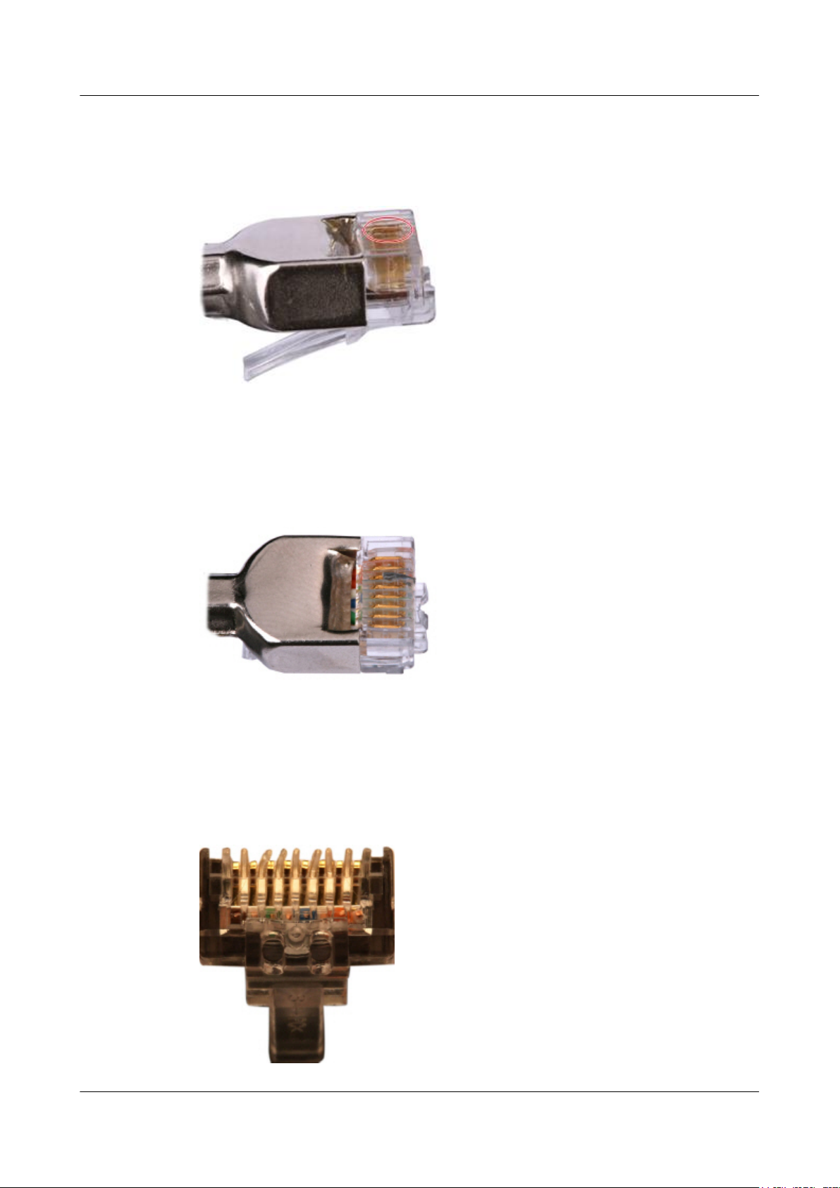
Huawei AP8030DN & AP8130DN
Hardware Installation and Maintenance Guide 5 Appendix
Step 2 Hold an RJ45 connector and turn it 45°. Observe the top edges of the metal contact strips. Figure
5-34 shows an unqualified piece.
Figure 5-34 Unparallel contact strips of different heights
Step 3 Check whether the contact strips are clean. If they are not clean and the dirt cannot be removed,
replace it with a new RJ45 connector. Figure 5-35 shows an unqualified piece.
Figure 5-35 Dirt on a contract strip
Step 4 Check whether the contact strips and the plastic separators are well aligned and intact. If a
separator is skew and cannot be fixed, replace it with a new RJ45 connector. Figure 5-36 shows
an unqualified piece.
Figure 5-36 Skew plastic separators
Issue 03 (2015-05-18) Huawei Proprietary and Confidential
Copyright © Huawei Technologies Co., Ltd.
69

Huawei AP8030DN & AP8130DN
Hardware Installation and Maintenance Guide
Step 5 Hold the connector with the side facing towards you, and check whether you can see the cross-
sections of the wires. Ensure that the ends of the wires are in good contact with the edge of the
RJ45, and that the contact strip blade extends beyond the ends of the wires and is crimped with
the wires. If not, replace the connector. Figure 5-37 shows an unqualified piece.
Figure 5-37 Wires not in good contact with the edge of the RJ45
5 Appendix
----End
Testing the Connection of Assembled Cables
Context
Huawei provides two types of Ethernet cables: straight-through cables and crossover cables.
l Straight-through cables are connected in a one-to-one manner. They are used to connect
terminals such as a computer or switch to network devices. Table 5-7 lists the connections
of core wires in a straight-through cable.
Table 5-7 Connections of core wires in a straight-through cable
RJ45 Connector 1 RJ45 Connector 2 Core Wire Color Twisted or Not
2 2 Orange Twisted
1 1 Orange-White
6 6 Green Twisted
3 3 Green-White
4 4 Blue Twisted
5 5 Blue-White
8 8 Brown Twisted
7 7 Brown-White
Issue 03 (2015-05-18) Huawei Proprietary and Confidential
Copyright © Huawei Technologies Co., Ltd.
70

Pin8
Pin1
Huawei AP8030DN & AP8130DN
Hardware Installation and Maintenance Guide
l Crossover cables are connected in a crossover manner. They are used to connect terminals
such as two computers or switches. Table 5-8 lists the connections of core wires in a
crossover cable.
Table 5-8 Connections of core wires in a straight crossover cable
RJ45 Connector 1 RJ45 Connector 2 Core Wire Color Twisted or Not
6 2 Orange Twisted
3 1 Orange-White
2 6 Green Twisted
1 3 Green-White
4 4 Blue Twisted
5 5 Blue-White
8 8 Brown Twisted
5 Appendix
Procedure
Step 1 Feed both connectors of the cable into the ports of the cable tester.
Step 2 After the connectors are properly inserted, turn on the tester. If the indicators from 1 to G turn
7 7 Brown-White
Figure 5-38 shows the pins of an RJ45 connector.
Figure 5-38 Pins of an RJ45 connector
on simultaneously, you can infer that the pins work normally and the wires are correctly
connected.
NOTE
Turn the switch to the S position to slow down lighting of the indicators so that you can see the indicators
more clearly, as shown in Figure 5-39.
Issue 03 (2015-05-18) Huawei Proprietary and Confidential
Copyright © Huawei Technologies Co., Ltd.
71

Huawei AP8030DN & AP8130DN
Hardware Installation and Maintenance Guide
Figure 5-39 Testing the conduction and connections of wires
5 Appendix
Step 3 Gently shake the connector and repeat Step 2 to check whether the metal contact strips are in
good contact with the core wires and Ethernet ports, as shown in Figure 5-40.
Figure 5-40 Checking the reliability
The procedure for testing a crossover cable is the same as that for testing a straight-through cable
except for the sequence in which the indicators turn on. You need to refer to the wire connections
of a crossover cable.
The Ethernet cable is qualified if the indicators turn on in the following sequence:
At the master (left) section of the tester, the indicators turn on in the sequence of 1-8-G. At the
slave (right) section of the tester, the indicators turn on in the sequence of 3-6-1-4-5-2-7-8-G.
Otherwise, the Ethernet cable is unqualified.
Issue 03 (2015-05-18) Huawei Proprietary and Confidential
Copyright © Huawei Technologies Co., Ltd.
72

Huawei AP8030DN & AP8130DN
Hardware Installation and Maintenance Guide 5 Appendix
NOTE
If a tester is not available, you can use a multimeter to perform a simple test, as shown in Figure 5-41.
Figure 5-41 Testing the connection of an Ethernet cable
----End
5.1.4 Installing Cable Accessories
Precautions for Installing Cable Accessories
Tools
NOTE
The illustrations in this document may differ from actual situations, but the installation methods remain
the same. For example, in this document, the adapters of cable connectors have separate interfaces. In the
actual situation, the adapters may have interfaces fixed on equipment.
Use dedicated tools provided or specified by Huawei and follow the installation procedure
described here.
Bending Radius
Unless otherwise specified, bending radiuses (R) of cables or fibers must meet the requirements
listed in Table 5-9.
Table 5-9 Bending radiuses of cables or fibers
Cable or Fiber Bending Radius (R)
Ordinary cable
In normal cases, R ≥ 2d. When the cable is
connected with a connector, R ≥ 5d.
Issue 03 (2015-05-18) Huawei Proprietary and Confidential
Copyright © Huawei Technologies Co., Ltd.
73

Huawei AP8030DN & AP8130DN
Hardware Installation and Maintenance Guide
Cable or Fiber Bending Radius (R)
5 Appendix
Fiber
NOTE
The letter d indicates the diameter of a cable or fiber.
Precautions for Installation
l Hold the terminals of cables instead of pulling the cables when installing or removing the
cable components.
l Do not insert a connector forcibly when the connector is blocked. Pull out the connector
by using a dedicated tool. Install the connector again after you check that the pins are
inserted properly.
l Before tightening screws on cable connectors, ensure that the connectors are properly
connected to their adapters. Tighten the screw with appropriate force using a flat-head or
Phillips screwdriver instead of bare hands or an electric screwdriver. If the screw cannot
be screwed into the tapped hole, find out the reason and try again. Do not screw it with too
much force, or the screw or adapter may be damaged.
l When removing densely aligned cables or fiber connectors, use dedicated pliers such as
cable-pulling pliers and fiber-pulling pliers.
R ≥ 40 mm (1.57 in.); Bending angle > 90°
l Do not twist, bend, stretch, or extrude fibers during installation.
l Cover the fiber connectors that are not in use by using dustproof caps. Remove the dustproof
caps before using the fiber connectors.
Requirements for Cable Routing
l To protect cables, remove the burrs in the cable through-holes or install protective rings in
the holes.
l To ease the connection and to avoid stress, keep slack at cable joints. After connecting
multiple cables to a connector that has multiple interfaces, keep the cables slack to avoid
stress generation.
l Bind or clean cables gently because cable distortion affects signal quality.
l Keep cables away from moveable components such as doors.
l Sharp objects must not be touched in cable wiring to ensure that cables are not damaged.
l To protect power cables, power cables of the active and standby power modules are laid
separately.
Installing Power Adapters
Installing the OT Terminal
Issue 03 (2015-05-18) Huawei Proprietary and Confidential
Copyright © Huawei Technologies Co., Ltd.
74

Huawei AP8030DN & AP8130DN
Hardware Installation and Maintenance Guide
Procedure
l Install an OT terminal.
1. Align the hole of the OT terminal (conductor upward) with a connecting hole, as shown
in Figure 5-42.
Figure 5-42 Aligning the OT terminal with a connecting hole
5 Appendix
NOTE
When you install an OT terminal, the crimping sleeve is installed as shown in Figure 5-43,
where A is correct and B is wrong.
Figure 5-43 Installing an OT terminal, showing the orientation of crimping sleeve
2. Place the spring washer and flat washer in turn, mount a matching screw, and fasten
it clockwise, as shown in Figure 5-44.
Issue 03 (2015-05-18) Huawei Proprietary and Confidential
Copyright © Huawei Technologies Co., Ltd.
75

Huawei AP8030DN & AP8130DN
Hardware Installation and Maintenance Guide
Figure 5-44 Installing two terminals back to back
NOTICE
5 Appendix
Ensure that the OT terminal is not in contact with other terminals or metal components.
3. Move the cable slightly and ensure that it is securely connected, as shown in Figure
5-45.
Figure 5-45 Installed OT terminal
l Install two OT terminals on a post.
Before you install two OT terminals on a post, ensure that the two terminals can be installed
on the post and that the electrical connecting pieces have a large contact area. Two OT
terminals can be installed using any of these methods:
– Bend the upper OT terminal at a 45- or 90-degree angle, as shown in Figure 5-46.
– Cross the two terminals, as shown in Figure 5-47.
Issue 03 (2015-05-18) Huawei Proprietary and Confidential
Copyright © Huawei Technologies Co., Ltd.
76

Huawei AP8030DN & AP8130DN
Hardware Installation and Maintenance Guide
Figure 5-46 Bending the upper OT terminal at a 45- or 90-degree angle
Figure 5-47 Crossing two terminals
5 Appendix
NOTICE
If the two terminals are different in size, place the smaller one above the bigger one. A
maximum of two terminals can be installed on a post.
l To remove an OT terminal, loosen the screw in the counterclockwise direction.
----End
Installing the Cord End Terminal
Procedure
Step 1 Hold a cord end terminal upright and place it on a terminal jack, as shown in Figure 5-48. To
ensure bump contact and dense connection, place the plain side of the terminal outwards.
Issue 03 (2015-05-18) Huawei Proprietary and Confidential
Copyright © Huawei Technologies Co., Ltd.
77

Huawei AP8030DN & AP8130DN
Hardware Installation and Maintenance Guide
Figure 5-48 Placing a terminal on a terminal jack vertically
Step 2 Insert the terminal into the jack vertically, and fasten the terminal by turning the matching screw
in the clockwise direction, as shown in Figure 5-49.
5 Appendix
Figure 5-49 Feeding the terminal into the jack
NOTICE
l
Ensure that the exposed section of the terminal should be less than 2 mm (0.079 in.) in length.
l Do not press the insulation of the terminal.
l Insert only one terminal into one jack.
Step 3 Move the cable slightly and ensure that it is securely connected.
Step 4 Before you remove a cord end terminal, loosen the screw in the counterclockwise direction.
----End
Installing Ethernet Adapters
Issue 03 (2015-05-18) Huawei Proprietary and Confidential
Copyright © Huawei Technologies Co., Ltd.
78

Huawei AP8030DN & AP8130DN
Hardware Installation and Maintenance Guide
Installing a Shielded Ethernet Connector
Procedure
Step 1 Hold the male and female connectors, with the male connector facing the female connector, as
shown in Figure 5-50.
Figure 5-50 Holding the male and female shielded connectors
5 Appendix
Step 2 Insert the male connector into the female connector, as shown in Figure 5-51.
Figure 5-51 Feeding the male shielded connector into the female shielded connector
Step 3 When you hear a click, the cable connector is completely inserted in the port. (The clip on the
cable connector pops up to fix the connector in the port.) Pull the connector slightly and ensure
that it is securely connected, as shown in Figure 5-52.
Issue 03 (2015-05-18) Huawei Proprietary and Confidential
Copyright © Huawei Technologies Co., Ltd.
79

Huawei AP8030DN & AP8130DN
Hardware Installation and Maintenance Guide
Figure 5-52 Installed shielded Ethernet connector
Step 4 To remove an Ethernet connector, press the locking key and pull out the connector, as shown in
Figure 5-53.
5 Appendix
Figure 5-53 Removing an shielded Ethernet connector
----End
Installing an Unshielded Ethernet Connector
Procedure
Step 1 Hold the male and female connectors, with the male connector facing the female connector, as
shown in Figure 5-54.
Issue 03 (2015-05-18) Huawei Proprietary and Confidential
Copyright © Huawei Technologies Co., Ltd.
80

Huawei AP8030DN & AP8130DN
Hardware Installation and Maintenance Guide 5 Appendix
Figure 5-54 Holding the male and female unshielded connectors
Step 2 Feed the male connector into the female connector, as shown in Figure 5-55.
Figure 5-55 Feeding the male connector into the female unshielded connector
Step 3 A crisp click indicates that the connector is locked by the locking key. Pull the connector slightly
and ensure that it is securely connected. Figure 5-56 shows an installed Ethernet connector.
Figure 5-56 Installed unshielded Ethernet connector
Issue 03 (2015-05-18) Huawei Proprietary and Confidential
Copyright © Huawei Technologies Co., Ltd.
81

Huawei AP8030DN & AP8130DN
Hardware Installation and Maintenance Guide
Step 4 To remove an Ethernet connector, press the locking key and pull out the connector, as shown in
Figure 5-57.
Figure 5-57 Removing an unshielded Ethernet connector
5 Appendix
----End
Installing Fiber Connectors
Context
NOTICE
l After you remove the dustproof cap, ensure that the fiber pins are clean and install them as
soon as possible.
l When you disassemble fiber connectors, you must use a dedicated tool if the connectors are
densely installed.
Cleaning Fiber Connectors
Procedure
Step 1 Clean the pins of a fiber connector by using lint-free cotton and alcohol.
Step 2 Clean the pins again by using dust-free cotton. If necessary, clean the pins by using an air gun.
Ensure that the pins are free from any fiber or debris.
----End
Issue 03 (2015-05-18) Huawei Proprietary and Confidential
Copyright © Huawei Technologies Co., Ltd.
82

Huawei AP8030DN & AP8130DN
Hardware Installation and Maintenance Guide
Installing an FC Fiber Connector
Procedure
Step 1 Remove the dustproof cap of the FC connector and store it for future use.
Step 2 Align the core pin of the male connector with that of the female connector, as shown in Figure
5-58.
Figure 5-58 Aligning the male connector with the female connector
5 Appendix
Step 3 Align the male connector with the female connector and gently push the male connector until it
is completely seated in the female connector, as shown in Figure 5-59.
Figure 5-59 Feeding the male connector into the female connector
Step 4 Fasten the locking nut in the clockwise direction and ensure that the connector is securely
installed, as shown in Figure 5-60.
Issue 03 (2015-05-18) Huawei Proprietary and Confidential
Copyright © Huawei Technologies Co., Ltd.
83

Huawei AP8030DN & AP8130DN
Hardware Installation and Maintenance Guide
Figure 5-60 Fastening the locking nut
Step 5 To disassemble an FC fiber connector, loosen the locking nut counterclockwise, and gently pull
the male connector, as shown in Figure 5-61.
5 Appendix
Figure 5-61 Disassembling an FC fiber connector
----End
Installing an LC Fiber Connector
Procedure
Step 1 Remove the dustproof cap of the LC fiber connector and store it for future use.
Step 2 Align the core pin of the male connector with that of the female connector, as shown in Figure
5-62.
Issue 03 (2015-05-18) Huawei Proprietary and Confidential
Copyright © Huawei Technologies Co., Ltd.
84

Huawei AP8030DN & AP8130DN
Hardware Installation and Maintenance Guide
Figure 5-62 Aligning the male connector with the female connector
Step 3 Align the male connector with the fiber adapter and gently push the male connector until it is
completely seated in the fiber connector, as shown in Figure 5-63.
Figure 5-63 Feeding the male connector into the female connector
5 Appendix
Step 4 A clicking sound indicates that the male connector is locked, as shown in Figure 5-64.
Figure 5-64 Installed LC connector
Issue 03 (2015-05-18) Huawei Proprietary and Confidential
Copyright © Huawei Technologies Co., Ltd.
85

Huawei AP8030DN & AP8130DN
Hardware Installation and Maintenance Guide
Step 5 To disassemble an LC fiber connector, press the locking nut to release the locking clips from
the bore, and gently pull the male connector, as shown in Figure 5-65.
Figure 5-65 Disassembling an LC fiber connector
5 Appendix
----End
Installing the SC Fiber Connector
Procedure
Step 1 Remove the dustproof cap of the SC fiber connector and store it for future use.
Step 2 Align the core pin of the male connector with that of the female connector, as shown in Figure
5-66.
Figure 5-66 Aligning the male connector with the female connector
Step 3 Feed the fiber connector into the female connector, with your fingers holding the shell of the
fiber connector (not the pigtail). When you hear a click, the fiber connector is secured by the
Issue 03 (2015-05-18) Huawei Proprietary and Confidential
Copyright © Huawei Technologies Co., Ltd.
86

Huawei AP8030DN & AP8130DN
Hardware Installation and Maintenance Guide
clips (internal parts, not illustrated in the figure). Pull the fiber connector gently. If the connector
does not loosen, the installation is complete. See Figure 5-67.
Figure 5-67 Installed SC fiber connector
5 Appendix
Step 4 To disassemble an SC fiber connector, hold the shell of the connector (do not hold the fiber) and
gently pull the connector in the direction vertical to the adapter. Unlock the male connector, and
then separate it from the shell, as shown in Figure 5-68.
Figure 5-68 Disassembling an SC fiber connector
----End
Installing an MPO Connector
Procedure
Step 1 Remove the dustproof cap of the MPO fiber connector and store it for future use.
Step 2 Align the core pin of the male connector with that of the female connector, as shown in Figure
5-69.
Issue 03 (2015-05-18) Huawei Proprietary and Confidential
Copyright © Huawei Technologies Co., Ltd.
87
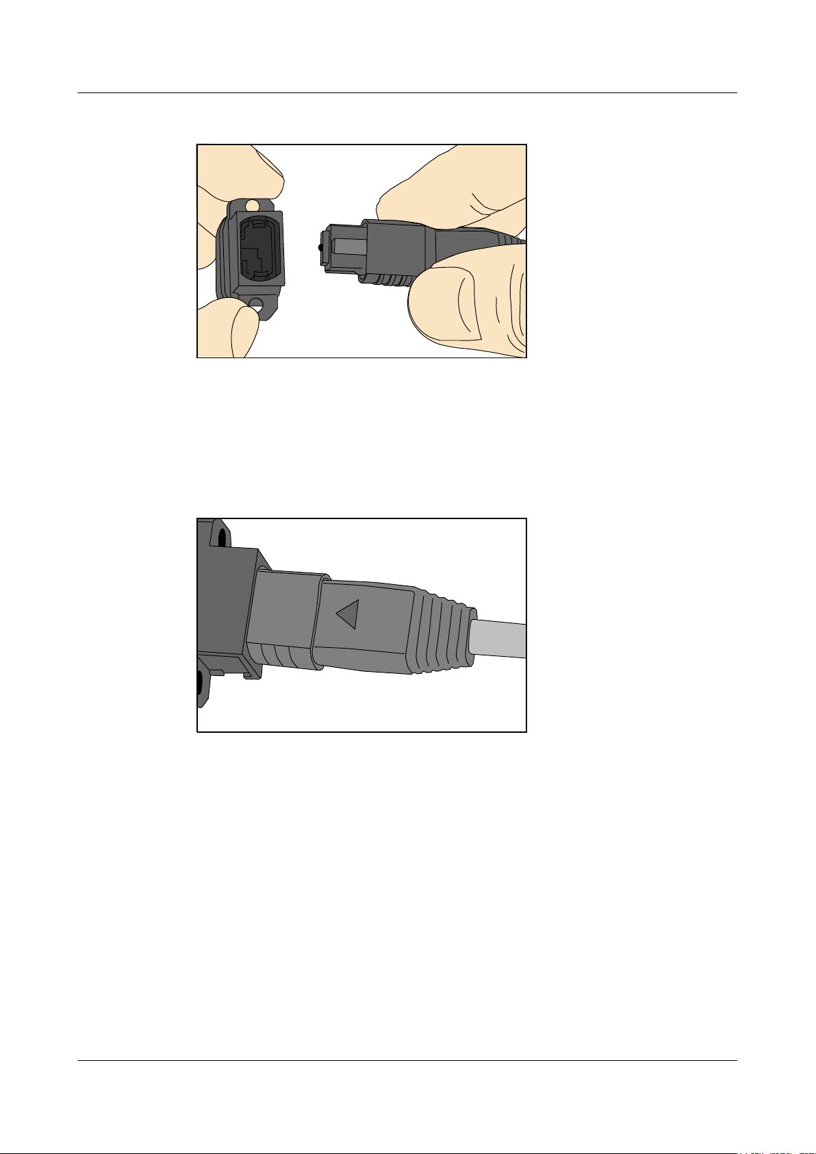
Huawei AP8030DN & AP8130DN
Hardware Installation and Maintenance Guide 5 Appendix
Figure 5-69 Aligning the male connector with the female connector
Step 3 Hold the shell labeled "PUSH" and feed the male connector into the female connector until you
hear a clicking sound. The male and female connectors are securely installed, as shown in Figure
5-70.
Figure 5-70 Installed MPO fiber connector
Step 4 To disassemble an MPO fiber connector, hold the shell labeled "PULL" and remove the male
connector, as shown in Figure 5-71.
Issue 03 (2015-05-18) Huawei Proprietary and Confidential
Copyright © Huawei Technologies Co., Ltd.
88

Huawei AP8030DN & AP8130DN
Hardware Installation and Maintenance Guide
Figure 5-71 Disassembling an MPO fiber connector
----End
5.1.5 Replacing the Mold of the Crimping Pliers
5 Appendix
Procedure
Step 1 Hold the handles of a pair of COAX crimping tools. Loosen the two fastening screws in the
Step 2 Hold the handles of the COAX crimping tools to open the self-locking mechanism. The jaw of
counterclockwise direction, as shown in Figure 5-72.
Figure 5-72 Loosening two fastening screws
the COAX crimping tools opens automatically, as shown in Figure 5-73.
Issue 03 (2015-05-18) Huawei Proprietary and Confidential
Copyright © Huawei Technologies Co., Ltd.
89

Huawei AP8030DN & AP8130DN
Hardware Installation and Maintenance Guide 5 Appendix
Figure 5-73 Pliers jaw opening automatically
Step 3 Remove the mould from the COAX crimping tools, as shown in Figure 5-74.
Figure 5-74 Removing the mould from the COAX crimping tools
Step 4 Place the mould to be installed into the jaw of the COAX crimping tools and align the screw
holes, as shown in Figure 5-75.
Issue 03 (2015-05-18) Huawei Proprietary and Confidential
Copyright © Huawei Technologies Co., Ltd.
90

Huawei AP8030DN & AP8130DN
Hardware Installation and Maintenance Guide
Figure 5-75 Installing a new mould in the COAX crimping tools
5 Appendix
NOTICE
Keep the short side of the mould inwards and the long side outwards, with the teeth of the mould
aligning from the larger size to the smaller size.
Step 5 Hold the handles of the COAX crimping tools tightly to match the mould and the jaw completely.
Align the screw holes, as shown in Figure 5-76.
Figure 5-76 Aligning the screw holes
Step 6 Hold the handles of the COAX crimping tools with one hand. Tighten the two fastening screws
in the clockwise direction. Figure 5-77 and Figure 5-78shows the mould installed in the COAX
crimping tools.
Issue 03 (2015-05-18) Huawei Proprietary and Confidential
Copyright © Huawei Technologies Co., Ltd.
91

Huawei AP8030DN & AP8130DN
Hardware Installation and Maintenance Guide
Figure 5-77 Mold installed in the COAX crimping tools
Figure 5-78 An installed mold
5 Appendix
----End
5.2 Environmental Requirements for Device Operation
5.2.1 Environmental Requirements for an Equipment Room
Requirements for Selecting a Site for an Equipment Room
When designing a project, consider the communication network planning and technical
requirements of the equipment. Also consider hydrographic, geological, seismic, power supply,
and transportation factors.
Construction, structure, heating and ventilation, power supply, lighting and fire fighting of the
equipment room should be designed by specialized construction designers to suit the
environmental requirements of devices. The equipment room should also follow local
regulations concerning the industrial construction, environmental protection, fire fighting, and
civil air defense. Construction must conform to government standards, regulations, and other
requirements.
Issue 03 (2015-05-18) Huawei Proprietary and Confidential
Copyright © Huawei Technologies Co., Ltd.
92

Huawei AP8030DN & AP8130DN
Hardware Installation and Maintenance Guide
The equipment room should be located at a place free from high temperature, dust, toxic gases,
explosive materials, or unstable voltage. Keep the equipment room away from significant
vibrations or strong noises, as well as power transformer stations.
The specific requirements for selecting a site for equipment room are as follows:
l The room should be located at a distance of at least 5 km (3.11 mi.) from heavy pollution
sources such as smelting and coal mines. It should be located at a distance of at least 3.7
km (2.30 mi.) from moderate pollution sources such as chemical, rubber, and galvanization
factories. It should be located at a distance of at least 2 km (1.24 mi.) from light pollution
sources such as packinghouses and tanyards. If these pollution sources cannot be avoided,
ensure that the equipment room is upwind of the pollution sources. In addition, adopt a
high-quality equipment room or protection products.
l The room should be located away from livestock farms, or in the upwind of the livestock
farms. Do not use an old livestock room or fertilizer warehouse as the equipment room.
l The equipment room must be far away from the residential areas. The equipment room that
is not far away from the residential areas must comply with equipment room construction
standards to avoid noise pollution.
l The doors and windows of the equipment room must be closed to keep an airtight room.
l Using steel doors to ensure sound insulation is recommended.
l No cracks or openings are allowed on the walls or floors. The outlet holes on the walls or
windows must be sealed. Walls must be constructed in the smooth, wear-resistant, dustproof
principles and produce the effect of flame retardant, sound insulation, heat absorption, dust
decrease, and electromagnetic shielding.
l The air vent of the room should be far from the exhaust of city waste pipes, big cesspools
and sewage treatment tanks. The room should be in the positive pressure state to prevent
corrosive gases from entering the equipment room and corroding components and circuit
boards.
l The room should be located far away from industrial and heating boilers.
l It is recommended that the room be on or above the second floor. If this requirement cannot
be met, the ground for equipment installation in the room should be at least 600 mm (23.62
in,) above the maximum flood level.
l The room should be at least 3.7 km (2.30 mi.) away from the seaside or salt lake. Otherwise,
the equipment room should be airtight with cooling facilities. In addition, alkalized soil
cannot be used as the construction material. Otherwise, equipment suitable for wet
conditions must be used.
l The equipment room should be strong enough to resist winds and downpours.
l The room should be located away from dusty roads or sand. If this is unavoidable, the doors
and windows of the equipment room must not face pollution sources.
l Do not place air conditioning vents near the equipment so that they blow directly on the
equipment because condensation may be blown into the equipment.
l Do not use decorative materials that contain sulfur in the equipment room.
5 Appendix
Equipment Room Layout
The equipment room is usually used to install mobile switching equipment, telecom transmission
equipment and power supply equipment as well as other auxiliary equipment. To ensure easy
maintenance and management, place the telecom equipment in different rooms. Figure 5-79
shows the layout of the equipment room.
Issue 03 (2015-05-18) Huawei Proprietary and Confidential
Copyright © Huawei Technologies Co., Ltd.
93

Control room Generator room
Transmission
room
Main communication
equipment room
Power distribution
room
Battery room
Substation room
Communication cable and optical cable
Power cable
Huawei AP8030DN & AP8130DN
Hardware Installation and Maintenance Guide 5 Appendix
Figure 5-79 Layout of the equipment room
Construction Requirements for the Equipment Room
The general layout principles of the equipment room are as follows:
l It should meet requirements for laying out and maintaining communication cables and
power cables.
l It should reduce the cabling distance, which eases cable maintenance, reduces potential
communication faults, and maximizes efficiency.
Table 5-10 shows the construction requirements for the equipment room.
Table 5-10 Construction requirements for the equipment room
Item Requirements
Area The smallest area of the equipment room can accommodate the equipment
with the largest capacity.
Net height The minimum height of the equipment room should not be less than 3 m
(9.84 ft). The minimum height of the equipment room is the net height
below overhead beams or ventilation pipes.
Floor The floor in the equipment room should be semi-conductive and dustproof.
A raised floor with an ESD covering is recommended. Cover the raised
floor tightly and solidly. The horizontal tolerance of each square meter
should be less than 2 mm (0.08 in.). If raised floors are unavailable, use a
static-electricity-conductive floor material, with a volume resistivity of 1.0
x 107 ohms to 1.0 x 10¹⁰ ohms. Ground this floor material or raised floor.
You can connect them to ground using a one megohm current-limiting
Load-bearing
resistor and connection line.
The floor must bear loads larger than 150 kg/m2 (0.21 bf/in.2).
capacity
Issue 03 (2015-05-18) Huawei Proprietary and Confidential
Copyright © Huawei Technologies Co., Ltd.
94
 Loading...