

Page 1

HP VISUALIZE J5000 /J7000
Owner’s Guide
HP VISUALIZE Computers
Manufacturing Part Number: A4978-90013
Edition E0299
© Copyright 1999 by Hewlett-Packard Company.
Page 2

Notice
UNIX is a registered trademark in the United States and other
countries, licensed exclusively through X/Open Company Limited.
The information contained in this document is subject to change without
notice.
Hewlett-Packard assumes no responsibility for the use or reliability of its
software on equipment that is not furnished by Hewlett-Packard.
This document contains proprietary information that is protected by
copy right. All rights reserved. No part of this document may be
photocopied, reproduced or translated to another language without the
prior written consent of Hewlett-Packard Company.
HEWLETT-PACKARD WARRANTY STATEMENT
HP PRODUCT DURATION OF WARRANTY
ISUALIZE J5000 /J7000 1 Year
HP V
1. HP warrantsHP hardware, accessories and supplies against defects in materials and workmanship
for the period specified above. If HP receives notice of such defects during the warranty period, HP
will, at its option, either repair or replace products which prove to be defective. Replacement
products may be either new or like-new.
2. HP warrants that HP software will not fail to execute its programming instructions, for the period
specified above, due to defects in material and workmanship when properly installed and used. If
HP receives notice of such defects during the warranty period, HP will replace software media
which does not execute its programming instructions due to such defects.
3. HP does not warrant that the operation of HP products will be uninterrupted or error free. If HP is
unable, within a reasonable time, to repair or replace any product to a condition as warranted, the
customer will be entitled to a refund of the purchase price upon prompt return of the product.
4. HP products may contain remanufactured parts equivalent to new in performance or may have
been subject to incidental use.
5. The warranty period begins on the date of delivery or on the date of installation if installed by HP.
If customer schedules installation or causes installation by HP to be delayed more than 30 days
after delivery, warranty begins on the 31st day from delivery.
6. Warranty does not apply to defects resulting from (a) improper or inadequate maintenance or
calibration, (b) software, interfacing, parts or supplies not supplied by HP, (c) unauthorized
modification or misuse, (d) operation outside of the published environmental specifications for the
product, or (e) improper site preparation or maintenance.
7. TO THE EXTENT ALLOWED BY LOCAL LAW, THE ABOVE WARRANTIES ARE EXCLUSIVE
AND NO OTHER WARRANTY OR CONDITION, WHETHER WRITTEN OR ORAL, IS
EXPRESSED OR IMPLIED AND HP SPECIFICALLY DISCLAIMS ANY IMPLIED
WARRANTIES OR CONDITIONS OF MERCHANTABILITY, SATISFACTORY QUALITY, AND
FITNESS FOR A PARTICULAR PURPOSE.
8. HP will be liable for damage to tangible property per incident up to the greater of $300,000 or the
actual amount paid for the product that is the subject of the claim, and for damages for bodily injury
or death, to the extent that all such damages are determined by a court of competent jurisdiction to
have been directly caused by a defective HP product.
2
Page 3

9. TO THE EXTENT ALLOWED BY LOCAL LAW, THE REMEDIES IN THIS WARRANTY
STATEMENT ARE CUSTOMER’S SOLE AND EXCLUSIVE REMEDIES. EXCEPT AS
INDICATED ABOVE, IN NO EVENT WILL HP OR ITS SUPPLIERS BE LIABLE FOR LOSS OF
DATA OR FOR DIRECT, SPECIAL, INCIDENTAL, CONSEQUENTIAL (INCLUDING LOST
PROFIT OR DATA), OR OTHER DAMAGE, WHETHER BASED IN CONTRACT, TORT, OR
OTHERWISE.
FOR CONSUMER TRANSACTIONS IN AUSTRALIA AND NEW ZEALAND: THE WARRANTY
TERMS CONTAINED IN THIS STATEMENT, EXCEPT TO THE EXTENT LAWFULLY
PERMITTED, DO NOT EXCLUDE, RESTRICT OR MODIFY AND ARE IN ADDITION TO THE
MANDATORY STATUTORY RIGHTS APPLICABLE TO THE SALE OF THIS PRODUCT TO
YOU.
RESTRICTED RIGHTS LENGEND. Use, duplication, or disclosure by
government is subject to restrictions as set forth in subdivision (c) (1) (ii)
of the Rights in Technical Data and Computer Software Clause at
DFARS 252.227.7013. Hewlett-Packard Co., 3000 Hanover St., Palo Alto,
CA 94304.
10 9 8 7 6 5 4 3 2 1
3
Page 4

4
Page 5

Contents
1. System Overview
System Requirements . . . . . . . . . . . . . . . . . . . . . . . . . . . . . . . . . . . . . . . .18
Product Description. . . . . . . . . . . . . . . . . . . . . . . . . . . . . . . . . . . . . . . . . .19
System Unit, Front View. . . . . . . . . . . . . . . . . . . . . . . . . . . . . . . . . . . . . .22
System LCD . . . . . . . . . . . . . . . . . . . . . . . . . . . . . . . . . . . . . . . . . . . . . .23
System Power Switch. . . . . . . . . . . . . . . . . . . . . . . . . . . . . . . . . . . . . . .23
Removable-Media Devices . . . . . . . . . . . . . . . . . . . . . . . . . . . . . . . . . . .23
System Unit Rear Panel Connectors . . . . . . . . . . . . . . . . . . . . . . . . . . . .24
Audio Connectors . . . . . . . . . . . . . . . . . . . . . . . . . . . . . . . . . . . . . . . . . .26
Keyboard Connectors . . . . . . . . . . . . . . . . . . . . . . . . . . . . . . . . . . . . . . .27
HP Parallel I/O Connector. . . . . . . . . . . . . . . . . . . . . . . . . . . . . . . . . . .27
802.3 Network Connectors. . . . . . . . . . . . . . . . . . . . . . . . . . . . . . . . . . .27
RS-232C Serial Input/Output Connectors . . . . . . . . . . . . . . . . . . . . . .28
SCSI Connectors. . . . . . . . . . . . . . . . . . . . . . . . . . . . . . . . . . . . . . . . . . .28
Power Cord Connectors . . . . . . . . . . . . . . . . . . . . . . . . . . . . . . . . . . . . .29
Keyboard and Mouse. . . . . . . . . . . . . . . . . . . . . . . . . . . . . . . . . . . . . . . . .30
Operating System Overview. . . . . . . . . . . . . . . . . . . . . . . . . . . . . . . . . . .31
Powering Up Your System. . . . . . . . . . . . . . . . . . . . . . . . . . . . . . . . . . . . .32
Getting Required Information. . . . . . . . . . . . . . . . . . . . . . . . . . . . . . . .33
Turning on the Power. . . . . . . . . . . . . . . . . . . . . . . . . . . . . . . . . . . . . . .35
Documentation . . . . . . . . . . . . . . . . . . . . . . . . . . . . . . . . . . . . . . . . . . . .36
Monitors. . . . . . . . . . . . . . . . . . . . . . . . . . . . . . . . . . . . . . . . . . . . . . . . . . .37
2. Changing Your Computer’s Hardware Configuration
Opening the System Unit . . . . . . . . . . . . . . . . . . . . . . . . . . . . . . . . . . . . .43
Removing the Front Panel. . . . . . . . . . . . . . . . . . . . . . . . . . . . . . . . . . .44
Opening the Top Cover. . . . . . . . . . . . . . . . . . . . . . . . . . . . . . . . . . . . . .46
Removing the Left and/or Right Panels . . . . . . . . . . . . . . . . . . . . . . . .47
5
Page 6

Contents
Reinstalling the Cover Panels . . . . . . . . . . . . . . . . . . . . . . . . . . . . . . . 48
Installing Memory . . . . . . . . . . . . . . . . . . . . . . . . . . . . . . . . . . . . . . . . . . 49
Installing DIMMs . . . . . . . . . . . . . . . . . . . . . . . . . . . . . . . . . . . . . . . . . 50
Installing a PCI-Type I/O Board . . . . . . . . . . . . . . . . . . . . . . . . . . . . . . . 55
Changing Your Monitor Type . . . . . . . . . . . . . . . . . . . . . . . . . . . . . . . . . 59
Setting the Monitor Type at Power-On . . . . . . . . . . . . . . . . . . . . . . . . 59
Setting the Monitor Type from the Boot Console Interface . . . . . . . . 59
CD Drive Installation. . . . . . . . . . . . . . . . . . . . . . . . . . . . . . . . . . . . . . . . 60
Verifying the CD Drive Operation . . . . . . . . . . . . . . . . . . . . . . . . . . . . 64
DDS Drive Installation . . . . . . . . . . . . . . . . . . . . . . . . . . . . . . . . . . . . . . 65
Verifying the DDS Tape Drive Operation . . . . . . . . . . . . . . . . . . . . . . 67
Floppy Drive Installation. . . . . . . . . . . . . . . . . . . . . . . . . . . . . . . . . . . . . 68
Verifying the Floppy Drive Configuration . . . . . . . . . . . . . . . . . . . . . . 71
3. Hot-Pluggable Hard Disk Drives
The Disk Drives . . . . . . . . . . . . . . . . . . . . . . . . . . . . . . . . . . . . . . . . . . . . 74
Removing a Hard Disk Drive . . . . . . . . . . . . . . . . . . . . . . . . . . . . . . . . 76
Putting a Disk Drive into its Tray . . . . . . . . . . . . . . . . . . . . . . . . . . . . 77
Inserting a Disk Drive . . . . . . . . . . . . . . . . . . . . . . . . . . . . . . . . . . . . . 79
The Hot-Plug Process. . . . . . . . . . . . . . . . . . . . . . . . . . . . . . . . . . . . . . . . 80
Replacing a Failed Disk Drive . . . . . . . . . . . . . . . . . . . . . . . . . . . . . . . 80
Hot-Plug Example. . . . . . . . . . . . . . . . . . . . . . . . . . . . . . . . . . . . . . . . . 81
The Hot-Plug Procedure . . . . . . . . . . . . . . . . . . . . . . . . . . . . . . . . . . . . 83
Checking the SCSI IDs . . . . . . . . . . . . . . . . . . . . . . . . . . . . . . . . . . . . . . 86
Using Device Files. . . . . . . . . . . . . . . . . . . . . . . . . . . . . . . . . . . . . . . . . 87
4. Using Your CD Drive
Operating the CD Drive. . . . . . . . . . . . . . . . . . . . . . . . . . . . . . . . . . . . . . 90
6
Page 7

Contents
The CD Drive . . . . . . . . . . . . . . . . . . . . . . . . . . . . . . . . . . . . . . . . . . . . .91
CD Media . . . . . . . . . . . . . . . . . . . . . . . . . . . . . . . . . . . . . . . . . . . . . . . .93
Loading and Unloading a CD in the disk Tray. . . . . . . . . . . . . . . . . . .94
Audio Control for the CD Drive . . . . . . . . . . . . . . . . . . . . . . . . . . . . . . . .95
Installing the xmcd Utility . . . . . . . . . . . . . . . . . . . . . . . . . . . . . . . . . .95
Using the xmcd Utility. . . . . . . . . . . . . . . . . . . . . . . . . . . . . . . . . . . . . .96
Mounting and Unmounting a CD. . . . . . . . . . . . . . . . . . . . . . . . . . . . . . .98
Mounting a CD Using SAM. . . . . . . . . . . . . . . . . . . . . . . . . . . . . . . . . .99
Unmounting a CD Using SAM . . . . . . . . . . . . . . . . . . . . . . . . . . . . . .100
5. Using Your Digital Data Storage (DDS) Tape Drive
DDS Tape Drive and Cassette Descriptions. . . . . . . . . . . . . . . . . . . . . .105
The DDS Drive . . . . . . . . . . . . . . . . . . . . . . . . . . . . . . . . . . . . . . . . . . .105
Data Cassettes . . . . . . . . . . . . . . . . . . . . . . . . . . . . . . . . . . . . . . . . . . .108
Setting the Write-Protect Tab on a Data Cassette. . . . . . . . . . . . . . .110
Operating the DDS Tape Drive. . . . . . . . . . . . . . . . . . . . . . . . . . . . . . . .111
Loading and Unloading a Data Cassette . . . . . . . . . . . . . . . . . . . . . .111
Using Device Files . . . . . . . . . . . . . . . . . . . . . . . . . . . . . . . . . . . . . . . .111
Archiving Data . . . . . . . . . . . . . . . . . . . . . . . . . . . . . . . . . . . . . . . . . . .112
Writing to a Data Cassette . . . . . . . . . . . . . . . . . . . . . . . . . . . . . . . . .112
Restoring Files from a Data Cassette to Your System . . . . . . . . . . . .113
Listing the Files on a Data Cassette. . . . . . . . . . . . . . . . . . . . . . . . . .113
Further Command Information. . . . . . . . . . . . . . . . . . . . . . . . . . . . . .114
Ordering Information . . . . . . . . . . . . . . . . . . . . . . . . . . . . . . . . . . . . . . .114
6. Using Your 3.5-Inch Floppy Disk Drive
Using the Floppy Diskette . . . . . . . . . . . . . . . . . . . . . . . . . . . . . . . . . . .117
Setting the Write-Protect Tab on a Diskette. . . . . . . . . . . . . . . . . . . .117
Inserting and Removing a Diskette. . . . . . . . . . . . . . . . . . . . . . . . . . .118
7
Page 8

Contents
Operating the Floppy Drive. . . . . . . . . . . . . . . . . . . . . . . . . . . . . . . . . . 119
Formatting a New Diskette . . . . . . . . . . . . . . . . . . . . . . . . . . . . . . . . 119
Transferring Data To and From a Floppy Diskette . . . . . . . . . . . . . 119
Listing the Files on a Floppy Diskette. . . . . . . . . . . . . . . . . . . . . . . . 121
For More Information. . . . . . . . . . . . . . . . . . . . . . . . . . . . . . . . . . . . . 121
Configuring the Floppy Driver. . . . . . . . . . . . . . . . . . . . . . . . . . . . . . 122
Ordering Information . . . . . . . . . . . . . . . . . . . . . . . . . . . . . . . . . . . . . 122
7. SCSI Connections
SCSI Bus Differences. . . . . . . . . . . . . . . . . . . . . . . . . . . . . . . . . . . . . . . 125
SCSI Restrictions . . . . . . . . . . . . . . . . . . . . . . . . . . . . . . . . . . . . . . . . . . 126
Cables . . . . . . . . . . . . . . . . . . . . . . . . . . . . . . . . . . . . . . . . . . . . . . . . . 126
Terminators. . . . . . . . . . . . . . . . . . . . . . . . . . . . . . . . . . . . . . . . . . . . . 128
Number of Devices Per SCSI Bus . . . . . . . . . . . . . . . . . . . . . . . . . . . 128
Considerations for Selecting SCSI Devices . . . . . . . . . . . . . . . . . . . . 128
SCSI Bus Length Constraints. . . . . . . . . . . . . . . . . . . . . . . . . . . . . . . . 130
Ultra Narrow Single-Ended SCSI Bus Length . . . . . . . . . . . . . . . . . 130
Ultra2 Wide Low-Voltage Differential SCSI Bus Length. . . . . . . . . 131
Assigning SCSI Device IDs . . . . . . . . . . . . . . . . . . . . . . . . . . . . . . . . . . 132
Assigning Ultra Narrow Single-Ended SCSI Device IDs . . . . . . . . . 133
Assigning Ultra2 Wide Low-Voltage Differential SCSI Device IDs. 134
Connecting to the SCSI Ports . . . . . . . . . . . . . . . . . . . . . . . . . . . . . . . . 135
System SCSI Port Connection . . . . . . . . . . . . . . . . . . . . . . . . . . . . . . 135
8. The Boot Console Interface
Boot Console Interface Features . . . . . . . . . . . . . . . . . . . . . . . . . . . . . . 138
Accessing the Boot Console Interface . . . . . . . . . . . . . . . . . . . . . . . . . . 141
Booting your Computer . . . . . . . . . . . . . . . . . . . . . . . . . . . . . . . . . . . . . 142
8
Page 9

Contents
Searching for Bootable Media. . . . . . . . . . . . . . . . . . . . . . . . . . . . . . . . .145
Resetting Your Computer . . . . . . . . . . . . . . . . . . . . . . . . . . . . . . . . . . . .146
Displaying and Setting Paths. . . . . . . . . . . . . . . . . . . . . . . . . . . . . . . . .147
Displaying and Setting the Monitor Type . . . . . . . . . . . . . . . . . . . . . . .149
The Monitor Command . . . . . . . . . . . . . . . . . . . . . . . . . . . . . . . . . . . .149
Displaying the Current Monitor Configuration. . . . . . . . . . . . . . . . . . .150
Setting the Monitor Type. . . . . . . . . . . . . . . . . . . . . . . . . . . . . . . . . . .151
Setting the Monitor Type at Power On. . . . . . . . . . . . . . . . . . . . . . . . . .153
Changing the Console to External Terminal . . . . . . . . . . . . . . . . . . . . .155
Displaying the Memory Configuration. . . . . . . . . . . . . . . . . . . . . . . . . .156
Memory Information Examples: 8-Slot J5000 . . . . . . . . . . . . . . . . . .157
Memory Information Examples: 16-Slot J7000 . . . . . . . . . . . . . . . . .159
Displaying the Status of the System I/O . . . . . . . . . . . . . . . . . . . . . . . .161
Setting the Auto Boot and Auto Search Flags . . . . . . . . . . . . . . . . . . . .162
Displaying and Setting the Security Mode. . . . . . . . . . . . . . . . . . . . . . .163
Displaying and Setting the Fastboot Mode . . . . . . . . . . . . . . . . . . . . . .164
Displaying the LAN Station Address . . . . . . . . . . . . . . . . . . . . . . . . . . .165
Displaying System Information . . . . . . . . . . . . . . . . . . . . . . . . . . . . . . .165
9. Troubleshooting
Common Problems and Solutions. . . . . . . . . . . . . . . . . . . . . . . . . . . . . .169
Dealing with a Boot Failure . . . . . . . . . . . . . . . . . . . . . . . . . . . . . . . . . .174
Memory Failures . . . . . . . . . . . . . . . . . . . . . . . . . . . . . . . . . . . . . . . . . . .175
LCD-Indicated Problems. . . . . . . . . . . . . . . . . . . . . . . . . . . . . . . . . . . . .176
Running System Verification Tests. . . . . . . . . . . . . . . . . . . . . . . . . . . . .177
9
Page 10

Contents
A. Safety and Regulatory Statements
Declaration of Conformity . . . . . . . . . . . . . . . . . . . . . . . . . . . . . . . . . . . 180
Emissions Regulations . . . . . . . . . . . . . . . . . . . . . . . . . . . . . . . . . . . . 181
Special Video Configuration Statements. . . . . . . . . . . . . . . . . . . . . . 182
VCCI Class 2 ITE . . . . . . . . . . . . . . . . . . . . . . . . . . . . . . . . . . . . . . . . 183
Laser Safety Statement (U.S.A. Only). . . . . . . . . . . . . . . . . . . . . . . . 184
Visible LEDs . . . . . . . . . . . . . . . . . . . . . . . . . . . . . . . . . . . . . . . . . . . . 184
Warnings and Cautions . . . . . . . . . . . . . . . . . . . . . . . . . . . . . . . . . . . 185
B. Environmental and Electrical Specifications
Environmental Specifications . . . . . . . . . . . . . . . . . . . . . . . . . . . . . . . . 188
Altitude . . . . . . . . . . . . . . . . . . . . . . . . . . . . . . . . . . . . . . . . . . . . . . . . 188
DC Magnetic Field Interference. . . . . . . . . . . . . . . . . . . . . . . . . . . . . 188
Temperature . . . . . . . . . . . . . . . . . . . . . . . . . . . . . . . . . . . . . . . . . . . . 188
Humidity (Non-condensing) . . . . . . . . . . . . . . . . . . . . . . . . . . . . . . . . 188
Leakage Current. . . . . . . . . . . . . . . . . . . . . . . . . . . . . . . . . . . . . . . . . 188
Shock . . . . . . . . . . . . . . . . . . . . . . . . . . . . . . . . . . . . . . . . . . . . . . . . . . 188
Vibration . . . . . . . . . . . . . . . . . . . . . . . . . . . . . . . . . . . . . . . . . . . . . . . 188
Electrical Specifications. . . . . . . . . . . . . . . . . . . . . . . . . . . . . . . . . . . . . 189
Power Requirements. . . . . . . . . . . . . . . . . . . . . . . . . . . . . . . . . . . . . . 189
Glossary
10
Page 11

Contents
11
Page 12

Contents
12
Page 13

Preface
This owner’s guide describes how to use your HP VISUALIZE J5000 or
J7000 computer.
This manual assumes that you have installed your computer as
described in the HP VISUALIZE J5000/J7000 Installation Card.
Audience
This guide is intended for HP VISUALIZE J5000/J7000 computer users.
Safety and Regulatory Statements
See Appendix A , “Safety and Regulatory Statements,” on page 179 for
the safety and regulatory statements that apply to the HP VISUALIZE
J5000/J7000 computer.
Installation Notice
Products designated in the applicable Hewlett-Packard price list as
customer-installable can be installed by computer-knowledgeable
customers who carefully read and follow the instructions provided.
Customers who elect to have the product installed by our field personnel
are charged the applicable field installation charge, as covered under the
standard terms and conditions. For more information, please contact
your local sales representative.
13
Page 14

Related Manuals
For more information, refer to one of the following documents:
• HP VISUALIZE J5000/J7000 Site Prep Guide
• HP VISUALIZE J5000/J7000 Installation Card
• Using HP-UX
• HP CDE Getting Started Guide and User’s Guide
• Managing Systems and Workgroups
• HP-UX System Administration Tasks
Note that most of the documents listed above can be viewed with a web
browser using this URL:
http://www.docs.hp.com
Revision History
The revision history for each edition of the manual is listed below:
Edition Revision History
E0299 First Printing
Problems, Questions, and Suggestions
If you have any problems or questions with our hardware, software, or
documentation, please contact either your HP Response Center or your
local HP representative.
14
Page 15

Documentation Conventions
Unless otherwise noted in the text, this guide uses the following symbolic
conventions.
Table 1 Documentation Conventions
user-supplied values Italic words or characters in syntax and command
descriptions represent “conceptual variables”—
whose values are indicated by the current context and
which you must supply. Italics are also used in text
for emphasis.
screen display Information that the system displays, commands that
you must use literally, and path names appear in this
typeface.
Enter Keycaps are presented with a special keycap font as
shown in the left column. (In this document, we refer
to the Enter key. On your keyboard, the key may be
labeled either Enter or Return.)
15
Page 16

Electrostatic Discharge (ESD) Precautions
Electrostatic discharges (static electricity) can damage the integrated
circuits on printed circuit boards and other internal devices. To prevent
such damage from occurring, observe the following precautions during
board unpacking and installation:
• Stand on a static-free mat.
• Wear a static strap to ensure that any accumulated electrostatic
charge is discharged from your body to ground.
• Connect all equipment together, including the static-free mat, static
strap, routing nodes, and peripheral units.
• Keep uninstalled printed circuit boards in their protective antistatic
bags.
• Handle printed circuit boards by their edges, once you have removed
them from their protective antistatic bags.
16
Page 17

1 System Overview
This chapter introduces the HP VISUALIZE J5000 and J7000 computers.
Its purpose is to familiarize you with your computer and its controls and
indicators.
17
Page 18
System Overview
System Requirements
System Requirements
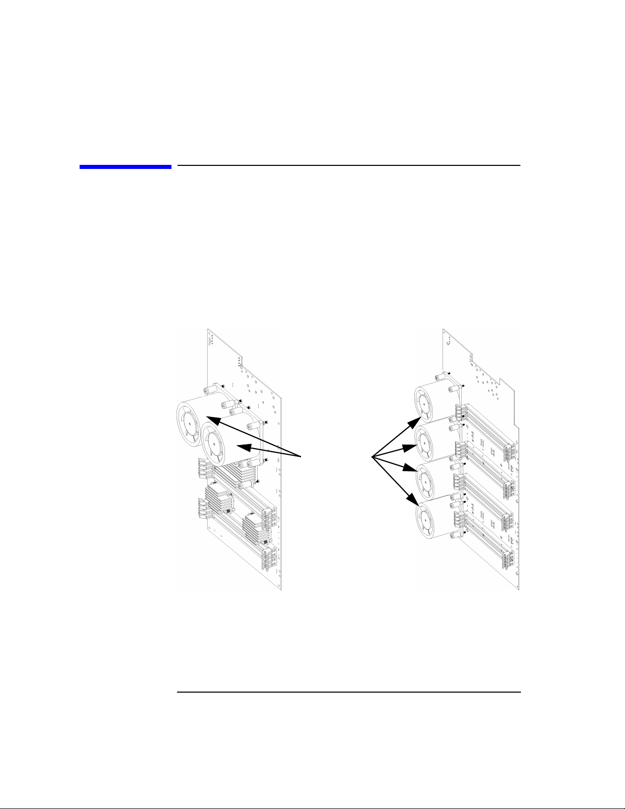
The HP VISUALIZE J5000 and J7000 computers are similar in may ways,
but the main way in which they differ is the number of processors: the
J5000 has two, and the J7000 has four. In addition to the label on the
front of the machine, you can also determine which machine you have by
counting the processors on the motherboard. Each one is cooled by a
cylindrical heat sink (a “turbocooler”) with dozens of airflow slots and an
integrated fan. The illustration below shows the two turbocoolers (and
hence two processors) of the J5000’s motherboard; the J7000 has four:
Figure 1-1 HP VISUALIZE J5000 /J7000 Processor-Count Difference
Processors with
integral turbocoolers
J5000
Instructions in this chapter assume that you are using the HP-UX 10.20
operating system with the Workstation Additional Core Enhancements
for HP-UX 10.20 (June1999). The J5000 requires just these two software
components; the J7000 may require an additional software component,
to be shipped when the J7000 itself is shipped.
18 Chapter1
J7000
Page 19

Product Description
To help you gain a better understanding of the J5000/J7000 computers,
the following table provides the computer’s key features.
Table 1-1 HP VISUALIZE J5000/J7000 Features
Computer Feature Description
Processors Two (in the J5000) or four (in the J7000)
440MHz PA8500 microprocessors with
0.5MB on-chip instruction cache and 1.0MB
on-chip data cache.
Operating System HP-UX 10.20 with the June 1999 Additional
Core Enhancements (ACE)
User Interface HP CDE graphical user interface
Compatibility Source- and binary-code compatible with the
C-Class and J-Class product families
System Overview
Product Description
Monitors List of compatible monitors:
• 19-inch, 1280×1024 color monitor
• 20-inch, 1280×1024 color monitor
• 21-inch, 1280×1024 color monitor
• 21-inch, 1600×1200 color monitor
Graphics Standard graphics:
•HPVISUALIZE-FX2 Pro
•HPVISUALIZE-EG
•HPVISUALIZE-FX6 Pro
Chapter 1 19
Page 20
System Overview
Product Description
Table 1-1 HP VISUALIZE J5000/J7000 Features
Computer Feature Description
Main Memory Using 256-MB DIMMs:
• J5000: Up to 2GB in 8 slots
• J7000: Up to 4GB in 16 slots
Using 512-MB DIMMs:
• J5000: Up to 4GB in 8 slots
• J7000: Up to 8GB in 16 slots
Internal Storage Devices Four hot-pluggable internal Ultra-2 Low
Voltage Differential (LVD) SCSI hard disk
drives, a standalone PC CD-ROM drive, and
a choice of either a PC floppy drive or a NSE
SCSI DDS tape drive.
Standard Network Ethernet IEEE 802.3 RJ45, UTP Twisted Pair
10/100 BaseT
Standard I/O More than 2GB/sec I/O bandwidth.
Standard computer I/O ports:
• Two Universal Serial Bus(USB) ports for
keyboard and mouse
• Two serial interface ports
• One parallel port (IEEE 1284)
• Ultra Narrow Single-Ended SCSI
• Wide Ultra-2 Low Voltage Differential
(LVD) SCSI
• Floppy interface
• ATAPI interface for CD-ROM
• Built-in 44KHz, 16-bit stereo audio ports
(line in, line out, microphone in, and
headphone out)
20 Chapter1
Page 21
Table 1-1 HP VISUALIZE J5000/J7000 Features
Computer Feature Description
System Overview
Product Description
PCI (Peripheral Connect
Interface) slots
Keyboard Universal Serial Bus (USB) keyboard
Mouse Universal Serial Bus (USB) mouse
Eight 64-bit slots in the following
arrangement:
1. 5V, 33MHz, bus 1, top slot (power only)
2. 5V, 33MHz, bus 2
3. 5V, 33MHz, bus 2
4. 3.3V, 66MHz, bus 3
5. 5V, 33MHz, bus 4
6. 5V, 33MHz, bus 4
7. 3.3V, 66MHz, bus 5
8. 5V, 33MHz, bus 4, bottom slot
Slots 4 and 7 (the 66-MHz slots) are the
primary FX Pro graphics slots.
Chapter 1 21
Page 22
System Overview
System Unit, Front View
System Unit, Front View
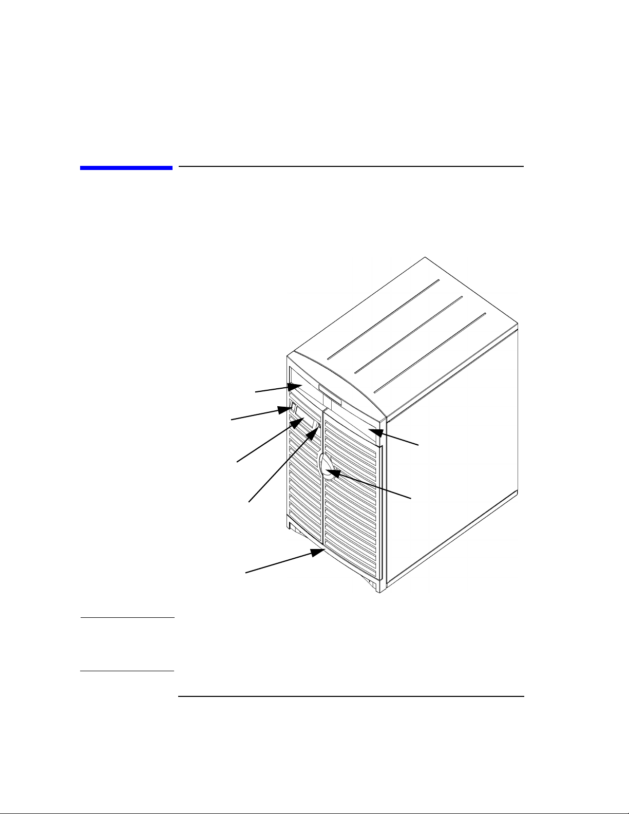
Before powering on your system, you should become familiar with the
system unit controls:
Figure 1-2 HP VISUALIZE J5000 /J7000 Front View
Floppy Drive or
DDS Drive Bay
Power Switch
CD Drive Bay
2-line, 16-character LCD
Panel lock
Lifting Ledge
Door Handle
CAUTION The Lifting Ledge is strong enough to use as a handhold when lifting the
unit. Note that the computer is designated for two-man lifting; it weighs
about 90 lbs. Do not attempt to lift it by yourself, or injury may result.
22 Chapter1
Page 23

System LCD
The Liquid Crystal Display (LCD) is located on the left side of the front
panel. The LCD displays messages about the state of the system,
including error codes (see “LCD-Indicated Problems” in the
Troubleshooting chapter for more details). The following symbols appear
in the LCD, representing the different system activities shown:
Figure 1-3 LCD Symbols
Operating System running
Disk access in progress
Receiving from network
Sending to network
System Power Switch
The power switch is used to turn the system unit on and off. The
workstations have a “soft power down” feature that shuts the system
down in a controlled manner. Hitting the power switch is identical to
logging in as root, and executing shutdown -q. Note that a soft power
down does not occur if you disconnect the power cord on the machine, or
if you disengage the power supply (by removing the interlocked
thumbscrew on the rear panel of the chassis).
System Overview
System Unit, Front View
Removable-Media Devices
Depending on your configuration, you can have a CD drive and your
choice of either a DDS tape drive or a floppy diskette drive.
NOTE You cannot have two of the same type of internal mass-storage device.
That is, you cannot have two CD drives, two floppy drives, or two DDS
drives, but you can have a CD drive and a floppy drive or a CD drive and
a DDS drive (you cannot have both a floppy drive and a DDS drive).
A description of each drive’s controls and indicators is in the chapter
describing that device, later in this document.
Chapter 1 23
Page 24

System Overview
System Unit Rear Panel Connectors
System Unit Rear Panel Connectors
This section describes the following connectors on the system unit’s rear
panel:
• Audio connectors (line in, line out, microphone and headphones)
• USB keyboard and mouse connectors
• HP parallel Centronics I/O connector
• 802.3 TP (Twisted Pair) LAN connector
• Two RS-232C serial I/O connectors
• Narrow Single-Ended (SE) SCSI connector
• Low-Voltage Differential (LVD) SCSI connector
• TOC (Transfer Of Control, or interrupt) button
• Power cord connector
NOTE To maintain FCC/EMI compliance, verify that all cables are fully seated
and properly fastened.
24 Chapter1
Page 25
System Unit Rear Panel Connectors
{
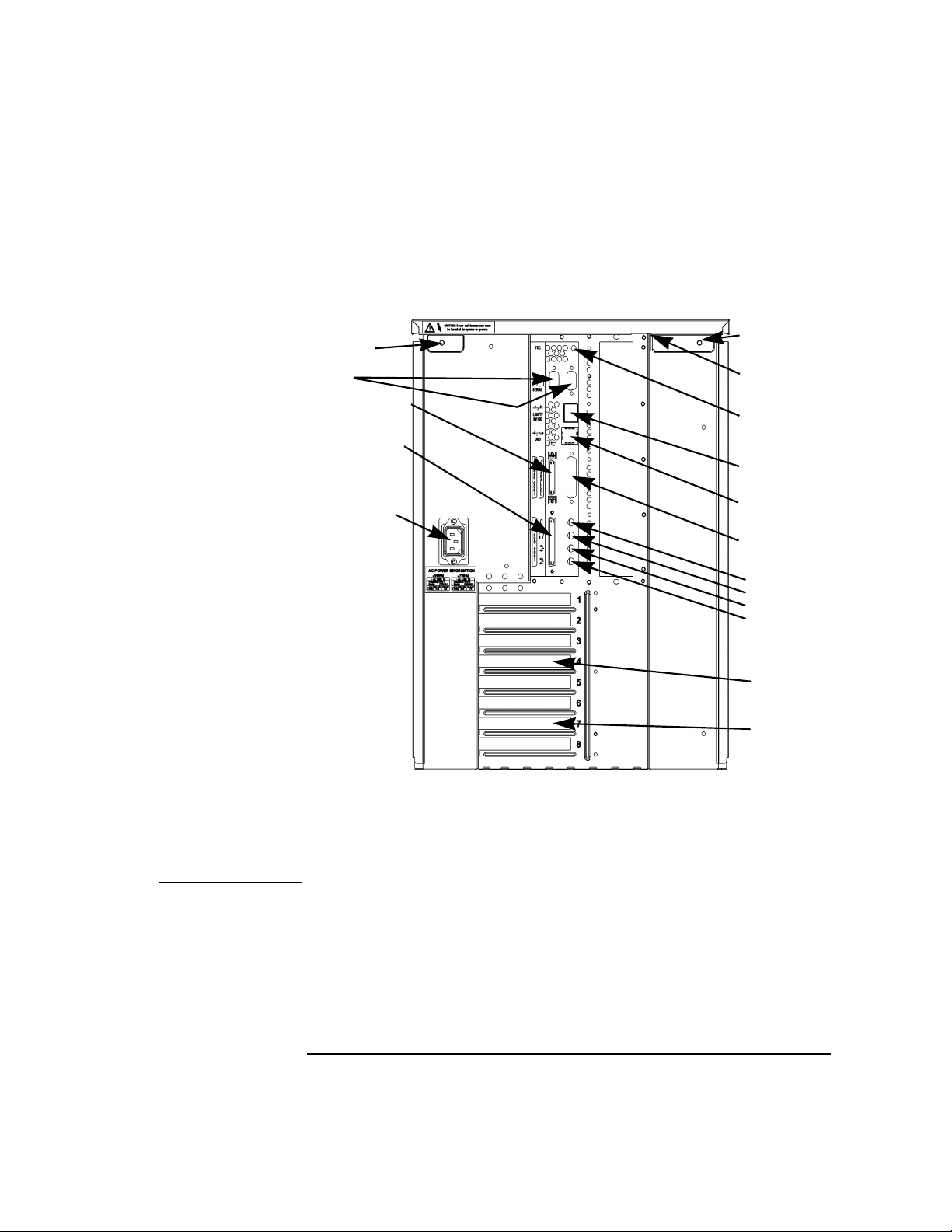
The illustration below shows the locations of the connectors on the
system unit’s rear panel.
Figure 1-4 System Unit Rear Panel Connectors
Power Supply
Interlock screw
(Torx T-15)
RS-232
System Overview
Thumbscrew
(T-15)
Security Tab
Narrow SE SCSI
Wide LVD SCSI
AC Power
(Auto-sensing)
I/O Slots
The two T-15 thumbscrews in the upper corners of the rear panel are the
keys to opening the machine: removing these two screws allows the top
panel to be removed, which in turn allows the left and right side panels
to be removed.
TOC/Interrupt
100Base-T
USB
Parallel
Audio:
Mic In
Headphones
Line out
Line in
Secondary
Graphics
Slot (Slot 4)
Primary
Graphics
Slot (Slot 7)
NOTE The upper-left thumbscrew (as seen from the back) is interlocked with
the power supply: loosening that screw disengages the power,
minimizing the shock danger while servicing. Make sure the interlocked
screw is firmly tightened when closing the unit, or the power supply
might still be disengaged.
Chapter 1 25
Page 26

System Overview
System Unit Rear Panel Connectors
Turning the power off with the power switch executes a clean shutdown,
but disengaging the power supply does not, so remember to power down
with the power switch!
Audio Connectors
Your computer has audio input and -output capability through an
internal speaker, as well as external input and output connectors on the
rear panel (see diagram of entire rear panel above, plus the close-up of
the audio connectors, below). The sound is 16-bit, 44kHz (CD-quality)
stereo sound.
Figure 1-5 Audio Connectors
Microphone (in)
Headphones (out)
Line Out
Line In
The audio connectors are standard stereo audio mini-jacks.
Hewlett-Packard recommends using gold-plated plugs available through
audio retailers for the best quality recording and playback through the
external connectors.
26 Chapter1
Page 27
A summary of the computer audio electrical specifications follows.
Table 1-2 Audio Electrical Specifications
Frequency Response 25Hz to 20kHz
Input Sensitivity/Impedance:
Line in
Microphone
Max Output
Level/Impedance Line out
Headphone
Speaker (internal)
Output Impedance
Line out
Headphone
Keyboard Connectors
The two USB connectors provide an interface for the keyboard and
mouse to the system (either connector can be used for either device).
Consult the documentation that accompanies each input device for
specific information concerning its use. Note that older non-USB
keyboards (PS-2 and HP-HIL keyboards) cannot be used with the J5000
and J7000.
System Overview
System Unit Rear Panel Connectors
2.0Vpk/47Kohm
22mVpk/1Kohm
2.8Vpp/47Kohm
2.75Vpp/50ohm
5.88Vpp/48ohm
619ohm
118ohm
HP Parallel I/O Connector
The 25-pin HP Parallel I/O interface uses Centronics interface protocols
to support peripheral devices such as printers and plotters. Consult the
documentation that accompanies each peripheral device for specific
information concerning its use.
802.3 Network Connectors
Your computer has built-in TP (Twisted Pair) connectors for the 802.3
(ethernet) or 100 BaseT network. Connections to ThinLAN networks
require an external transceiver. Your computer will automatically select
the correct network setting.
Chapter 1 27
Page 28

System Overview
System Unit Rear Panel Connectors
RS-232C Serial Input/Output Connectors
You can attach peripheral devices to the RS-232C Serial Input/Output
(SIO) ports on this computer. Peripheral devices include printers,
plotters, modems, and scanners. Consult the documentation that
accompanies each pointing or peripheral device for specific information
concerning its use.
The SIO ports are programmable; that is, you can choose attributes such
as bit rate, character length, parity, and stop bits either by selecting the
corresponding device file (in /dev), or by using SAM (the System
Administration Manager). The SIO ports are used as an interface for
serial asynchronous devices to the CPU. The ports operate at up to a
115.2Kbaud rate.
The table below shows the SIO connector pin listings. The serial
connectors are 9-pin D-sub connectors. Signal names are those specified
in the EIA RS-232 standard.
Table 1-3 Serial I/O Pins
Pin No. Signal Description
1 DCD Data Carrier Detect
2 RXD Receive Data
3 TXD Transmit Data
4 DTR Data Terminal Ready
5 GND Ground
6 DSR Data Set Ready
7 RTS Request To Send
8 CTS Clear To Send
9 RI Ring Indicator
SCSI Connectors
Use the Narrow Single-Ended SCSI connector and/or the Wide LVD
(Low-Voltage Differential) SCSI connectors to connect external SCSI
devices such as hard disk drives, optical disk drives, DDS-format tape
28 Chapter1
Page 29
System Overview
System Unit Rear Panel Connectors
drives and CD-ROM drives. Consult the documentation that
accompanies each SCSI device for specific information concerning its use.
Refer to the appendix “SCSI Connections” for information about
connecting SCSI devices to your computer.
WARNING Do not attach FWD SCSI devices to the LVD SCSI port, or
damage will occur.
NOTE When attaching external SCSI devices, be sure to terminate the last
device on each external SCSI bus. The terminators are included in a
small plastic bag that was shipped with your machine. Before powering
up your computer, make sure that the last external SCSI device in each
SCSI chain has a terminator.
If you have no external SCSI devices, install the terminators directory on
the connectors on the rear panel of the computer.
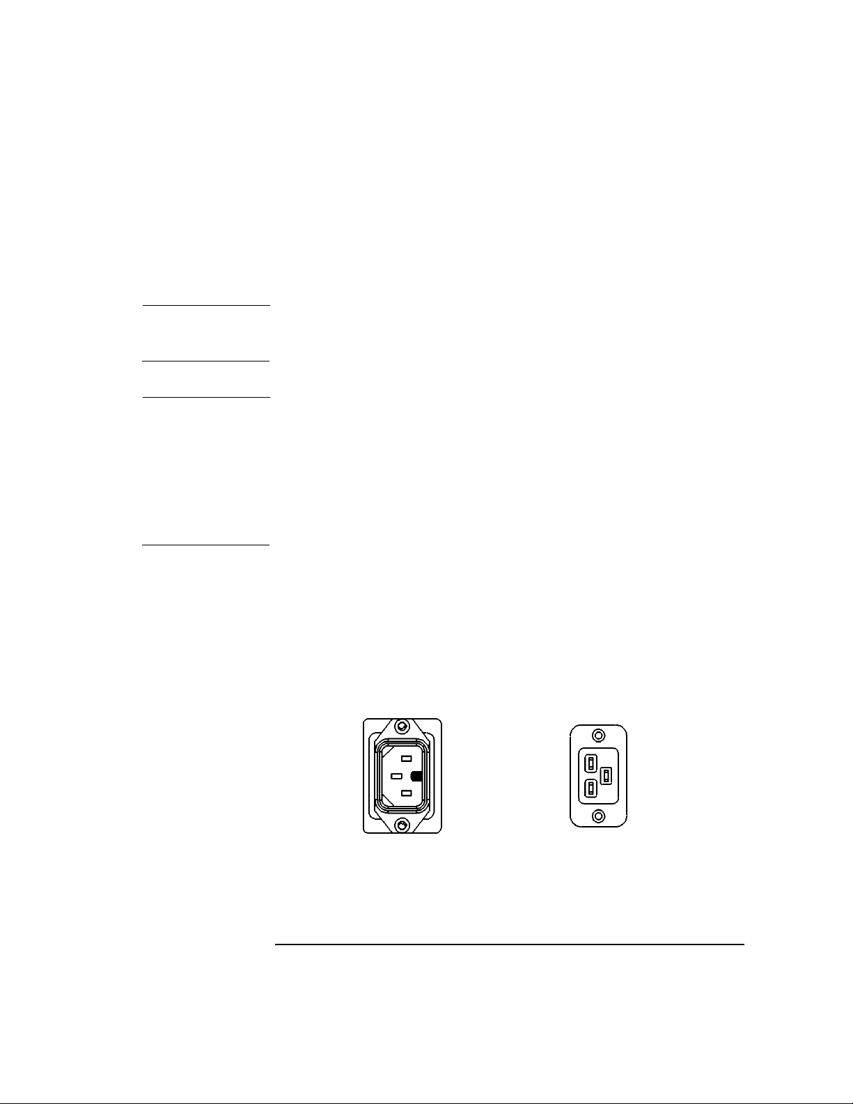
Power Cord Connectors
Plug the workstation’s power cord into the power cord connector to
provide AC power to the system. Note that the HP VISUALIZE J5000 and
J7000 have different types of power cords, because of their differing
power requirements:
Figure 1-6 Power Connectors
The power connector on the left is used on the J5000 (notice that it is a
keyed connector, requiring a 15-amp circuit), and the one on the right is
used on the J7000 because of its greater power demand (20 amps).
Chapter 1 29
Page 30

System Overview
Keyboard and Mouse
Keyboard and Mouse
At this printing, only the HP three-button USB mouse is supported as a
pointing device for the J5000 and J7000.
For general information on using three-button mice and on the various
cursor shapes associated with different areas of HP CDE while using a
mouse or other pointing device, see Using Your HP Workstation. Other
supported USB devices are the HP USB keyboard and HP USB hub.
Since the only USB devices supported at this time are keyboards and
mice, the USB hub’s main purpose is currently that of an “extension
cord” to allow a greater distance between the keyboard/mouse and the
computer.
The mouse and keyboard can be plugged into either USB port on the
back of the computer.
30 Chapter1
Page 31

System Overview
Operating System Overview
Operating System Overview
Your computer uses version 10.20 of the HP-UX operating system with
the June 1999 Workstation ACE (Addition Core Enhancements). Instant
Ignition systems (systems with preloaded software) have X-Windowsand
Hewlett-Packard’s graphical user interface HP CDE installed and
configured (see the HP CDE Getting Started Guide and User’s Guide for
details).
Please refer to the “Instant Ignition System Configuration Information”
sheet that came with your system for details on configuration.
If your Instant Ignition system does not have the kernel preconfigured
with all of the device drivers, you need to refer to the manual Managing
Systems and Workgroups to configure your kernel as appropriate for your
set of hardware and peripheral devices.
If you have any questions about Instant Ignition, refer to HP-UX System
Administration Tasks for more information.
Chapter 1 31
Page 32

System Overview
Powering Up Your System
Powering Up Your System
After you have connected the various parts of the computer—for details,
see the J5000/J7000 Installation Sheet that came with your computer—
you are ready to power up the system. At this point, there are two
possibilities:
• Your computer has been “ignited;” that is, the HP’s Instant Ignition
process has installed the operating system already. In this case, when
you power up the computer, you will be presented with a series of
questions asking you the machine’s hostname, IP address, subnet
mask, and other basic configuration questions (see next page for
details). When these are answered, the CDE login screen will appear.
• Your computer has not been “ignited;” that is, the HP’s Instant
Ignition process has not installed the operating system already. In
this case, you will need to install the operating system from the CDs
found in the HP-UX 10.20 Software for Workstations ACE (June
1999) media kit; for details, see the CD Booklet included with the
CDs. The ACE bundles reside on the IPR media, and are also
available from http://www.software.hp.com/ACE. When the
operation system (HP-UX 10.20) and the HP-UX 10.20 ACE (June
1998) are both installed, you’ll need to answer the questions noted
above for the ignited system. After the questions have been answered,
the CDE login screen will appear.
Once the CDE login screen appears, and you can log in as root—initially,
there is no password. When you have logged in, you will be able to create
other users’ accounts and do whatever other configuration and
installations you require to get the machine into its desired state. Use
the Help facility of SAM (the System Administration Manager) or see the
HP CDE Getting Started Guide and User’s Guide for instructions on
typical tasks.
32 Chapter1
Page 33

System Overview
Powering Up Your System
Getting Required Information
The start-up procedure for your workstation will require you to supply
the following information. Please have this information available before
you turn the workstation on for the first time.
NOTE If you are not the system administrator for your workstation, and
therefore do not know the information, ask your system administrator.
Here is the information you will need. You may want to fill in the blanks
so the answers will be readily available during the configuration phase.
• Host name: ___________________________________
The host name is sometimes called the “system name.”
• IP (Internet Protocol) address: _______________________________
You will need this address if you are connecting the workstation to a
local area network.
• Time zone: _________________
This is the time zone in which the workstation is located.
• Optional networking parameters
Ask your system administrator if you need to configure these
parameters.
Table 1-4 Networking Parameters
Subnetwork mask _____________
Network gateway IP address _____________
Local domain name _____________
DNS server host name _____________
DNS server IP address _____________
Network Information Service domain name _____________
Chapter 1 33
Page 34

System Overview
Powering Up Your System
• Optional font server parameters
You need to supply these parameters if you want the workstation to
obtain its fonts from a network server. Ask your system administrator
if you need to configure these parameters.
Table 1-5 Font-Server Parameters
Font server name _____________
Font server IP address _____________
34 Chapter1
Page 35

System Overview
Powering Up Your System
Turning on the Power
1. Turn on the monitor and any external peripherals (for example,
printers) connected to the workstation.
2. Turn on the workstation. The workstation will run a series of
self-tests.
3. After two or three minutes, a series of messages are displayed as
various hardware and software subsystems are activated. Unless
something is wrong with your system, you are not asked to respond to
these messages.
4. A series of windows appears requesting the information you gathered
in the previous section, such as your host name, IP address, and time
zone. Enter the information as it is requested.
NOTE You should enter the host name when requested; otherwise, you will get
an error message when you log in.
If you do not have other pieces of information, press Enter to use the
default value. You can provide missing information later by logging into
a terminal emulator window as superuser and executing this command:
/sbin/set_parms
5. The next question asks if you want to set a root password. The root
password is the password used for the account of the “superuser”—a
special user who has permission to perform all system administration
tasks. The username for the superuser is root.
6. When you have finished answering all of the questions, the
workstation completes its start-up sequence and displays the CDE
login screen.
7. Log into your first CDE session as root. For information on logging
into CDE, see the Common Desktop Environment User’s Guide.
Chapter 1 35
Page 36

System Overview
Powering Up Your System
NOTE You must log into the first session as root. This is because the system
contains no other user accounts. Once you are done with system
configuration, including the creation of other users’ accounts via SAM
(the System Administration Manager), you should log out as superuser
and log back in as one of the other users.
Documentation
The documentation for your system is located on the Instant Information
CD. To access this CD, you need to follow the special mounting
instructions that come with it.
36 Chapter1
Page 37

Monitors
You can use one of the following HP monitors with your computer:
• 19-inch, 1280×1024 color monitor (A4575A)
• 19-inch, 1600×1200 color monitor (A4575A)
• 21-inch, 1280×1024 color monitor (A4576A)
• 21-inch, 1600×1200 color monitor (A4576A)
Before using your monitor, you should become familiar with its controls,
connectors and indicators. For information on these controls and
indicators and on using your monitor, see the documentation that came
with the monitor. To confirm your graphics configuration, use SAM (the
System Administration Manager) as follows.
As root, run /usr/sbin/sam, and the following splash screen appears to
indicate that SAM is running:
Figure 1-7 SAM’s Splash Screen
System Overview
Monitors
Chapter 1 37
Page 38

System Overview
Monitors
After a few seconds of analyzing your hardware and software
configurations, the splash screen disappears, and another window
appears, which offers access to the various administration tasks:
Figure 1-8 SAM’s Main Menu
Double-click the “Display” icon, and something like the following appears
(of course, the actual devices on your machine are likely to be different):
Figure 1-9 X Server Configuration Screen
38 Chapter1
Page 39

Double-clicking on any of the icons that represent graphics devices (or
single-clicking and then selecting Describe... under the Actions menu) will
cause a monitor-description window to appear; for example:
Figure 1-10 Monitor Description Window
System Overview
Monitors
Other options under the Actions menu allow you to identify the physical
monitor associated with the logical monitor (by making the screen image
blink), and to change the monitor type and/or gamma-correction value.
By selecting X Server Configuration (under the List menu), you can see and
configure your graphics device in terms of X server parameters. For
example, when you double-click on any of the icons that represent
X-Windows screens (or single-click and then select Describe... under the
Actions menu), you’ll see information similar to the following:
Chapter 1 39
Page 40

System Overview
Monitors
Figure 1-11 X-Window Screen Description Window
As before, other options under the Actions menu allow you to identify the
physical monitor associated with the X-screen definition (again, by
making the screen image blink), and to change the default visual, screen
options, server options, etc.
40 Chapter1
Page 41

2 Changing Your Computer’s
Hardware Configuration
This chapter describes the procedures required to change your
computer’s hardware configuration.
41
Page 42

Changing Your Computer’s Hardware Configuration
The instructions in this chapter assume you are using the HP-UX 10.20
operating system with the Workstation Additional Core Enhancements
for HP-UX 10.20 (June 1999) and the HP CDE interface.
CAUTION When installing internal devices, always wear a properly grounded wrist
strap to avoid damaging components with electrostatic discharge (static
electricity).
Use the following tools to remove or replace hardware parts when
changing your configuration:
• Light-duty flat blade screwdriver with a 150mm (6-inch) blade
• Number 1 Posidriv driver
• T10, T15 and T20 Torx drivers
• Needle-nosed pliers
Also, read the ESD Precautions elsewhere in this guide.
NOTE Many of the HP-UX commands in this chapter will require that you
become superuser (root). If you cannot log in as root, contact your
system administrator.
To make access to the internal components easier, you may want to place
the computer on a table or workbench instead of leaving it on the floor.
CAUTION This computer is designated for two-man lifting; it weighs approximately
90 pounds. Do not attempt to lift it by yourself, or injury may result.
42 Chapter2
Page 43

Changing Your Computer’s Hardware Configuration
Opening the System Unit
Opening the System Unit
Some hardware-configuration operations, like installing and removing
hard disk drives, can be done simply by opening the door on the front of
the unit; the disk drives are accessible through the open door. Other
operations require a bit more access to the interior of the computer, so
more panels will need to be removed. Such operations include the
installation and removal of the following devices (along with a list of
which panels will need to be removed):
• CD drive (front panel, top cover)
• DDS drive (front panel, top cover)
• Floppy drive (front panel, top cover)
• Memory (top cover, left side)
• I/O cards (top cover, right side)
Before opening the front, top, left, or right panels of the unit, make sure
that the system is powered down and unplugged. Note: do not remove
the rear thumbscrews before powering down the unit, or the system power
will be interrupted due to the interlock.
1. Power off the system (either by executing shutdown -h as root and
then turning off the power, or by simply hitting the power switch,
which accomplishes the same thing), the monitor, and any peripheral
devices.
2. Unplug the power cord of the system unit and any peripheral devices
from AC wall outlets.
3. Attach the static-grounding wrist strap by following the instructions
on the package. Attach the sticky end of the wrist strap to bare metal
on the back panel of the system unit.
CAUTION Do not attempt to operate the computer with any of the front, top, or side
covers removed. In addition to maintaining FCC/EMI compliance, the
covers are needed to ensure proper airflow, and hence, sufficient system
cooling. Operating the unit without its covers in place may void the
warranty.
Chapter 2 43
Page 44
Changing Your Computer’s Hardware Configuration
Opening the System Unit
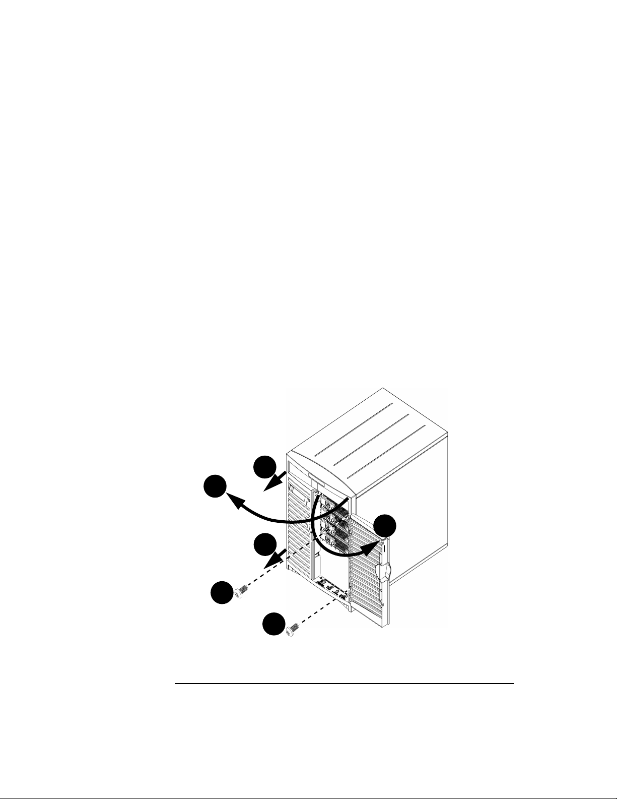
Removing the Front Panel
The front panel must be removed in order to install a CD drive, a DDS
tape drive, or a floppy drive—see their respective sections later in this
chapter for detailed instructions on the installation process for each type
of device. If you need to remove the front panel (the panel that contains
the door), perform the following steps:
1. Shut down and unplug the system as described above. Unlock the
door on the front of the unit, if necessary, and swing it open.
2. Remove the two panel-detach screws on the right edge of the panel,
visible after you open the door.
3. Swing (clockwise) the entire front panel open 45 to 90 degrees—the
hinges are on the left, as you look at the front of the unit.
4. Once you have swung the panel open on the hinges on the left, pull it
straight out to remove it.
Figure 2-1 Removing the Front Panel
4
3
1
4
2
2
To replace the front panel, perform the above steps in the reverse order.
44 Chapter2
Page 45

Changing Your Computer’s Hardware Configuration
Opening the System Unit
Figure 2-2 System Unit with Front Cover Panel Removed
Floppy Drive or
DDS Drive Bay
Panel hinge hole
LCD Connector
Power switch
System LCD
Removable
hard disk drives
Panel hinge holes
CD Drive
Panel-detach
screw holes
Once the front panel has been removed, a CD drive, DDS drive, and/or a
floppy drive can be installed or removed.
Chapter 2 45
Page 46

Changing Your Computer’s Hardware Configuration
Opening the System Unit
Opening the Top Cover
To open the top cover of the unit—to install or remove a
removable-media drive (i.e., a CD drive, a DDS tape drive, or a floppy
drive), DIMMs, or I/O cards, for example, or for other access to the inside
of the unit—follow these steps:
1. Shut down and unplug the system as described in “Opening the
System Unit” on page 43.
2. Remove the two thumbscrews in the top corners of the back panel.
The upper-left one (when looking at the back of the unit) has a
power-supply interlock, and removing the screw disengages the
power to the unit, reducing shock hazard during the configuration
process. Note that cutting off power via the power-supply interlock
does not do a clean shutdown like pressing the power switch does.
Figure 2-3 Removing the Thumbscrews
Thumbscrew
(with power-supply
interlock)
Thumbscrew
3. Slide the top panel an inch or two toward the rear of the machine,and
then remove it by lifting straight up. The top panel fits snugly, so you
may have to get a firm grip on it in order to slide it back.
46 Chapter2
Page 47
Changing Your Computer’s Hardware Configuration
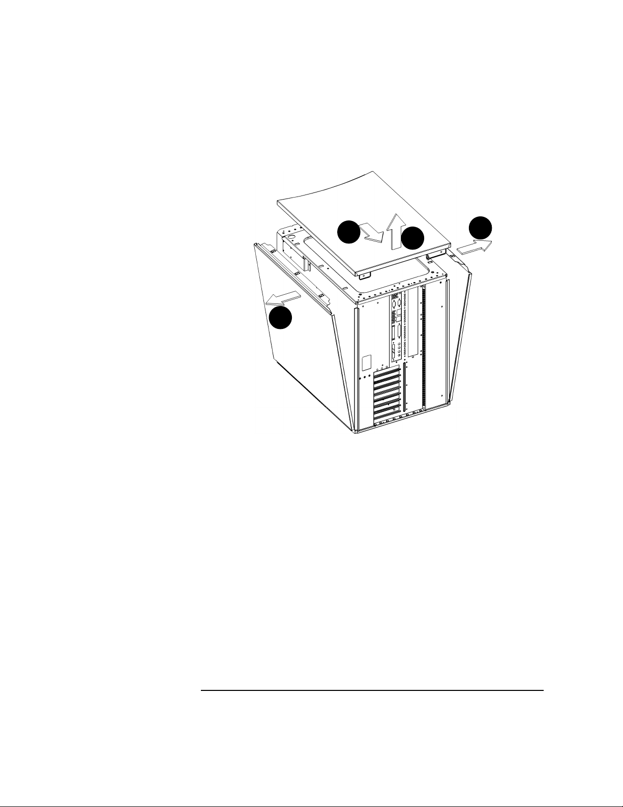
Figure 2-4 Removing the Top and Side Panels
Opening the System Unit
1
2
3
3
Removing the Left and/or Right Panels
In order to remove the left and/or right panels, you must first remove the
top panel, as described above. Then, the left and right panels are free to
tip out and away from the unit. The side panels stay in place after the
top panel is removed because of three locations on the friction-fit tab
running along the top edge of the side panels. After the desired side
panel has been tipped out and away from the chassis, as shown in the
illustration above, it can be lifted straight up.
The left panel (which on the right in the illustration above, since you are
looking at the back of the machine) must be removed to install or remove
memory (DIMMs), and the right panel (which on the left in the
illustration above, since you are looking at the back of the machine) must
be removed to install or remove I/O cards.
Chapter 2 47
Page 48

Changing Your Computer’s Hardware Configuration
Opening the System Unit
Reinstalling the Cover Panels
To replace the cover panels once you’ve taken them off, perform the
following steps:
1. Place the left- and right-side panels into their grooves in the bottom
edges of the left and right sides of the chassis, and then press the tops
of the side panels together firmly.
2. Place the top cover on the top of the chassis, about an inch of its back
edge protruding over the rear panel. Then, push it straight forward,
so its front edge slides underneath the lip of the front panel’s top
edge. The top panel fits snugly, so you may have to get a firm grip on
it in order to slide it forward.
3. Reinsert the two thumbscrews into the tabs in the upper corners of
the back panel of the chassis. Note that the upper left one (as looking
at the rear panel) is the power supply interlock screw, so make sure it
is tightened snugly, or the power supply may not engage.
48 Chapter2
Page 49
Changing Your Computer’s Hardware Configuration
Installing Memory
This section contains information regarding the installation of additional
memory. However, before continuing with this section, please take time
to read the following list of considerations:
• Use the procedure described in the chapter “The Boot Console
Interface” to determine the current memory configuration for your
computer. This should be done before trying to install additional
DIMMs (Dual Inline Memory Modules) into your computer.
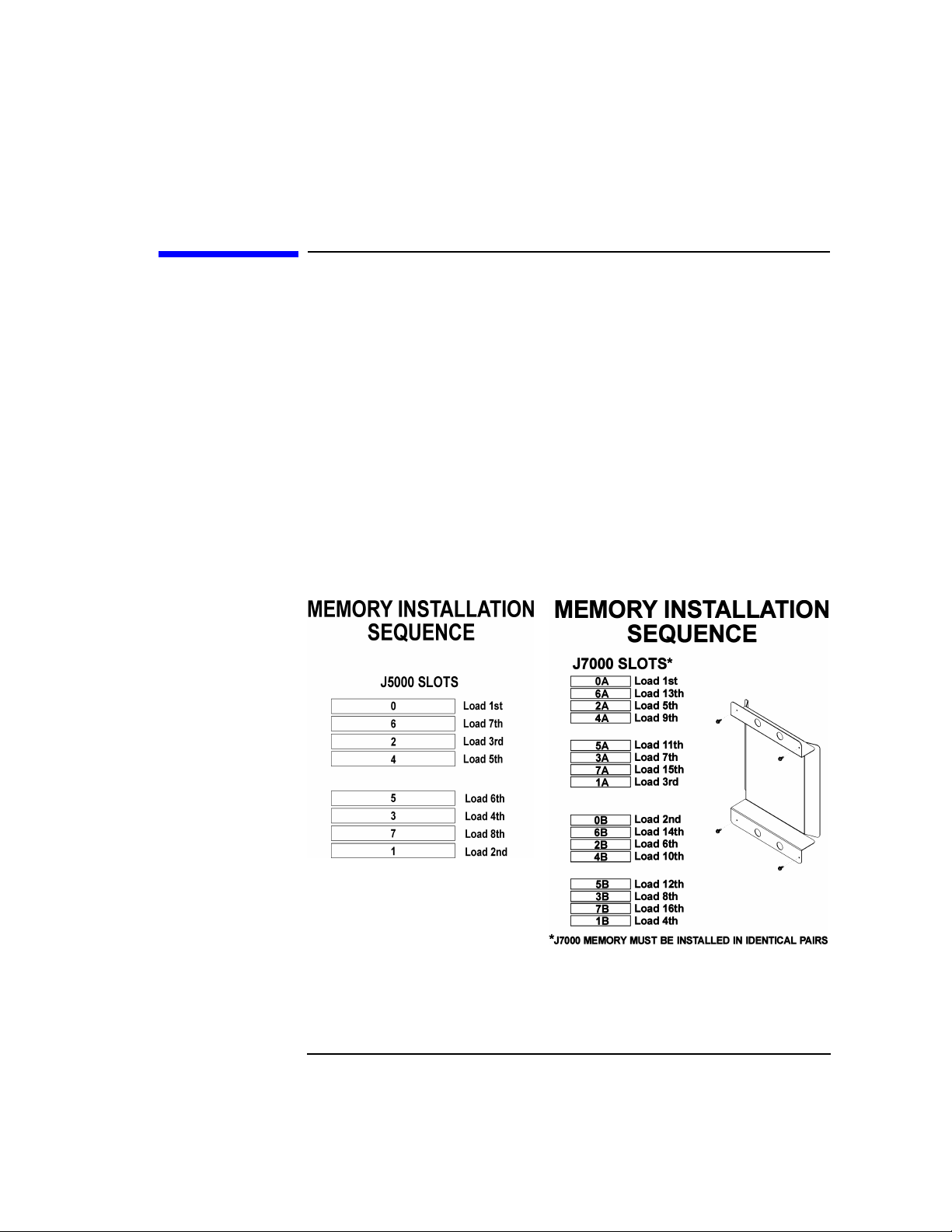
• Familiarize yourself with the order in which DIMMs must be
inserted; the order differs, depending on whether you have a J5000
(eight memory slots) or a J7000 (sixteen memory slots). This
information is on a label on the floor of the left side of the J5000, and
on the main air guide in the J7000. The labels look like this:
Figure 2-5 DIMM-Insertion Order for J5000 and J7000
Installing Memory
• For the J5000—the two-processor model—insert the DIMMs in the
sequence indicated in the left illustration above (or on the label inside
the left side of the machine). For the J7000—the four-processor
model—insert the DIMMs in pairs of equal memory size, and in the
Chapter 2 49
Page 50

Changing Your Computer’s Hardware Configuration
Installing Memory
order indicated in the right illustration above (or on the label on the
air guide). For details on the mechanics of inserting DIMMs, see the
following pages.
• When you have finished installing the additional DIMMs, use the
Boot Console Interface to verify that the computer recognizes them.
Installing DIMMs
Perform the following steps to add DIMMs to your computer.
1. Open the system unit according to the directions in “Opening the
System Unit” on page 43. You’ll need to remove the top panel and the
left side panel (looking from the front). Here is roughly what the
inside of a J5000 looks like: the DIMMs are accessible as soon as you
remove the side panel:
Figure 2-6 The J5000 DIMM Slots (as seen from the open left side)
DIMM Slots
The J7000, on the other hand, requires one additional step before the
DIMMs are accessible. Because it has twice the number of processors
as the J5000, the J7000 requires greater cooling capacity to prevent
components from overheating. This is effected, in part, by two
sheet-metal air guides that channel the airflow directly at the
processors’ turbocoolers. One of these air guides, in addition to
channeling the airflow to the processors, also hides the DIMM slots,
50 Chapter2
Page 51
Changing Your Computer’s Hardware Configuration
Installing Memory
so it must be removed before installing or removing DIMMs. Before
the air guide is removed, the open left side of the J7000 looks like
this:
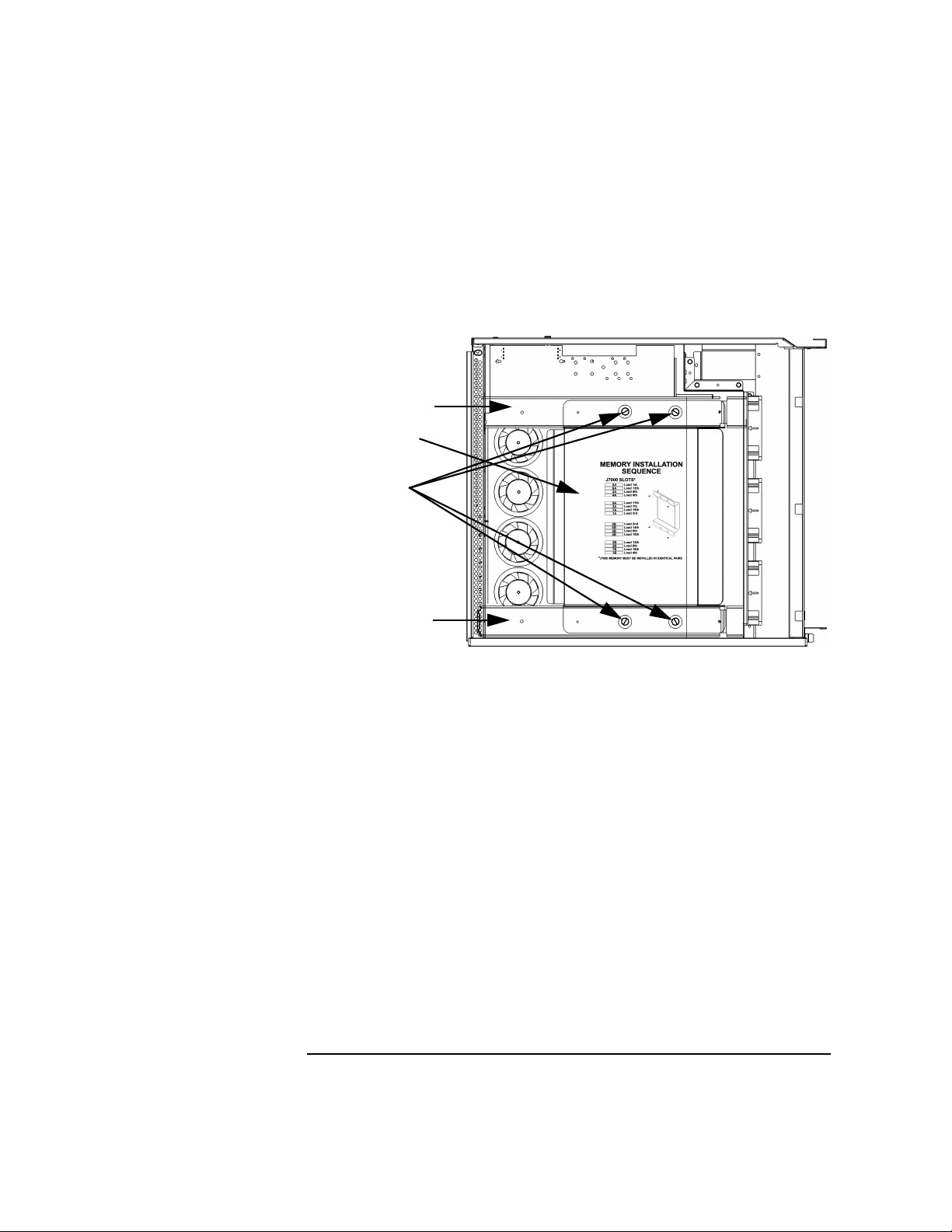
Figure 2-7 The J7000’s Open Left Side Before Removing Air Guide
Support Bar
Air Guide
Screws
Support Bar
Remove the four screws that secure the air guide to the support bars.
Be sure, as you remove the last screw, that you hold onto the air guide
so it doesn’t fall.
Chapter 2 51
Page 52
Changing Your Computer’s Hardware Configuration
Installing Memory
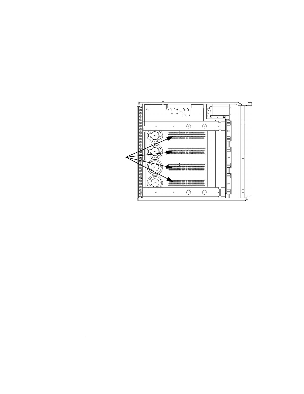
After the air guide is removed, the open left side of the J7000 looks
like this:
Figure 2-8 The J7000’s Open Left Side After Removing Air Guide
DIMM Slots
(16 total)
52 Chapter2
Page 53

2. Install DIMMs in the order indicated in Figure 2-5 on page 49, or on
the label on the floor of the chassis (the J7000 requires DIMMs to be
installed in pairs of the same size). Make sure the DIMM-removal
tabs are angled out—away from each other. The DIMMs are keyed;
that is, there are notches in the edge (see Figure 2-10, below) that
prevent the DIMM from being inserted upside down. Once the DIMM
is oriented correctly (the notches in the DIMM lining up with the
bumps in the slot), press firmly and evenly on each DIMM to ensure
that it seats properly; the DIMM-removal tabs will rotate to become
parallel as the DIMM is inserted:
Figure 2-9 Inserting a DIMM
White
DIMM-removal
tab
Changing Your Computer’s Hardware Configuration
Installing Memory
Black
DIMM-removal
tab
3. To remove a DIMM, push these tabs away from each other, and the
DIMM will be removed from its socket.
Figure 2-10 Removing a DIMM
White
Chapter 2 53
Black
Page 54

Changing Your Computer’s Hardware Configuration
Installing Memory
4. Re-install the air guide with the four screws removed earlier (so it
again looks like Figure 2-7 on page 51), close the system unit and
reconnect all cables.
5. Verify that this installation was successful by following the steps in
“Displaying the Memory Configuration” on page 156.
If you have only replaced a faulty DIMM, you must execute the pdt
clear command in the service menu of the Boot Console Interface.
Answer yes (Y) to the prompt “Continue? (Y/N) >
54 Chapter2
Page 55
Installing a PCI-Type I/O Board
The J5000/J7000 are extensible by means of I/O cards thatoffer a variety
of functionalities, and the kind of I/O cards supported are called PCI
(Peripheral Component Interconnect) cards. PCI cards can be 3.3-volt or
5-volt cards (or both; these are called “universal” cards), and they can
also be 32-bit or 64-bit cards, and 33MHz or 66MHz.
The graphics boards supported by the J5000/J7000 computers are the
HP VISUALIZE-FX2Pro and the HP VISUALIZE-FX6Pro. While these are
universal cards and will work in any slot, they should be used in slots 4
or 7 to obtain optimal performance.
Your J5000/J7000 computer’s PCI assembly has eight 64-bit slots in the
following arrangement (this information is also on the label on the floor
of the right side of the chassis):
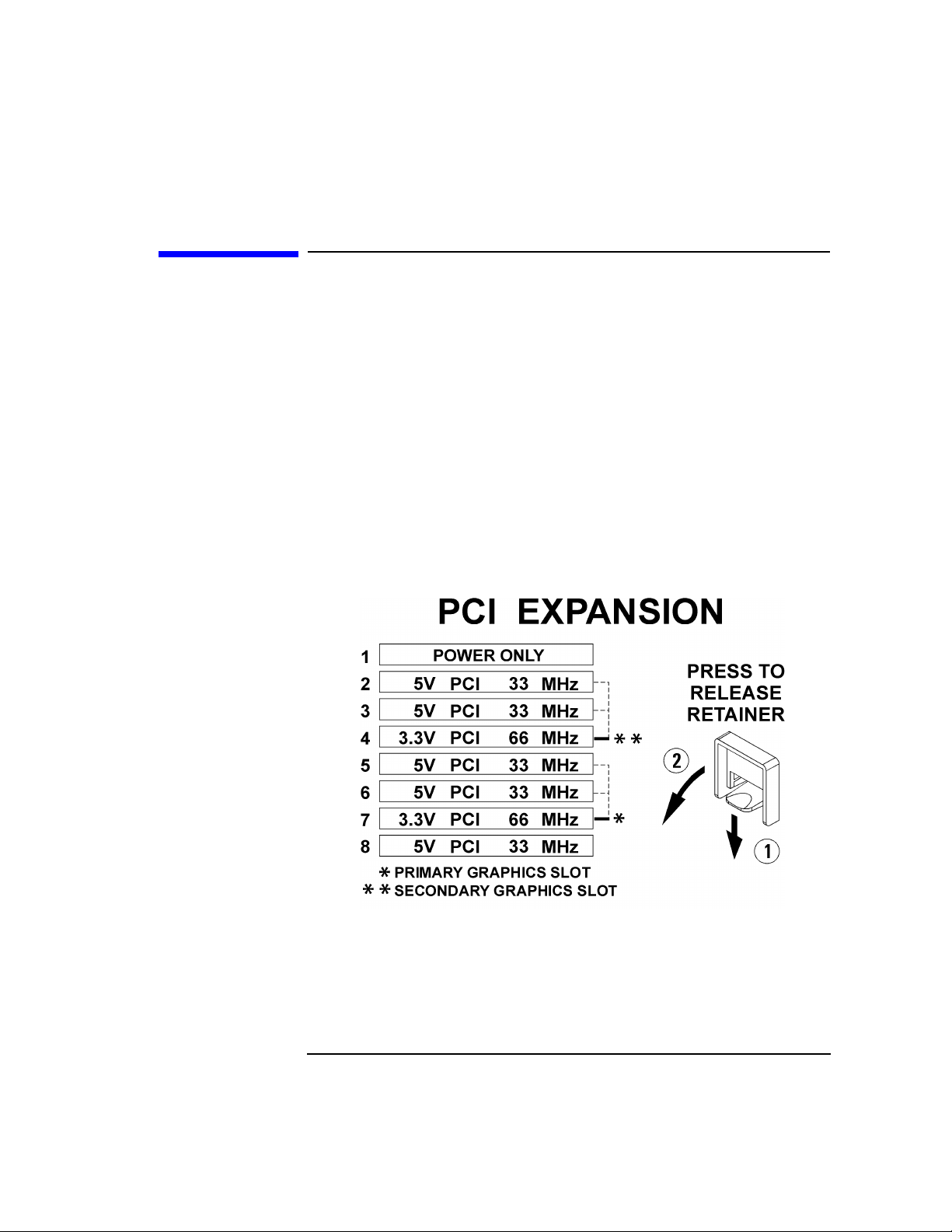
Figure 2-11 The PCI Slot Label
Changing Your Computer’s Hardware Configuration
Installing a PCI-Type I/O Board
As the illustration above indicates, graphics cards should be inserted
into the 66MHz slots in order to deliver maximum performance. Use Slot
7 first, and then Slot 4. Once Slots 7 and 4 are used, graphics cards can
be added to any slot that physically has room, except Slot 1. Slot1isa
power-only slot; that is, it doesn’t offer data communication to the card
inserted there. In other words, a two-board sandwich—main card in Slot
Chapter 2 55
Page 56
Changing Your Computer’s Hardware Configuration
Installing a PCI-Type I/O Board
2, drawing power and sending/receiving data, and daughter board in Slot
1, drawing only power—is supported. On the other hand, a standalone
card that draws power and sends/receives data would be supported in
Slot 2 but not Slot 1. Note that a two-card sandwich “in” Slot 7 means
that the bottom card is in Slot 7, and top card is in Slot 6.
For non-graphics cards, insert them in this order: Slot 2, then 8, 3, 5, and
finally 6. If Slots 7 and 4 are not needed for graphics cards, they can be
used for very-high-bandwidth general I/O.
CAUTION The J5000 and J7000 supply approximately 264 watts of power to the
PCI slots. Thus, if you use three HP VISUALIZE-FX6Pro cards
simultaneously (in Slots 7, 4, and 2), as in the HP VISUALIZE Center
configuration, there are some power constraints imposed on the
remaining slots. Each HP VISUALIZE-FX6Pro card, while electrically
connected to only one slot, takes the physical space of two, and each card
draws about 78 watts. So, three FX6Pro cards will occupy six of the eight
PCI slots and will draw 234 watts altogether, leaving only about 30 watts
for the remaining two slots combined, should you choose to use them. Do
not insert PCI cards that together draw more than 264 watts, or damage
to your computer may result.
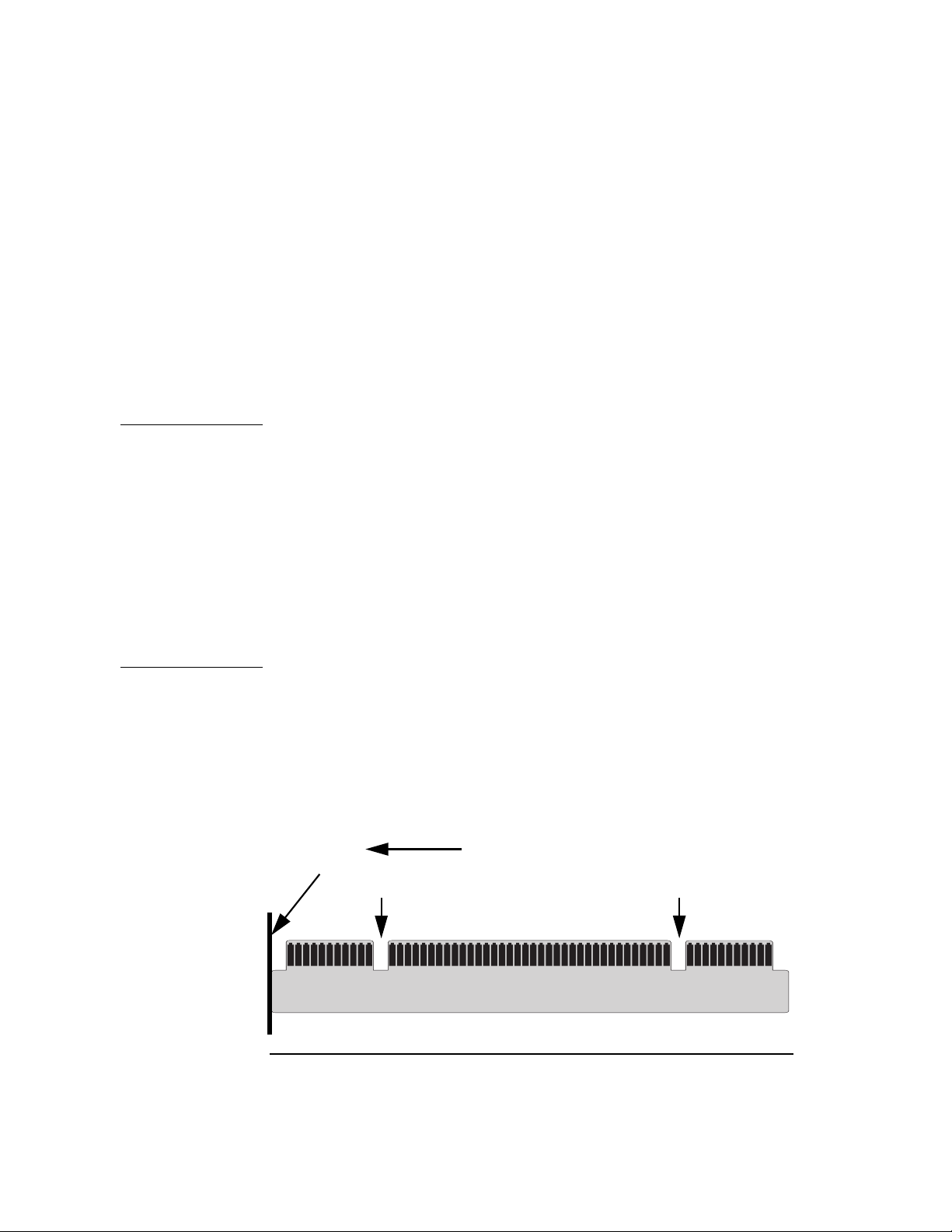
PCI card edge connectors have one or two small notches in them (see
illustration below). The 3.3-volt notch indicates that the card can operate
properly on 3.3 volts, and the 5-volt notch indicates that the card can
operate properly on 5 volts. As you might expect, notches in both
locations indicates that the card is a universal PCI card; that is, it will
operate properly on either voltage.
Figure 2-12 The PCI Edge Connector
PCI Card Backplate
3.3-volt notch
56 Chapter2
Back of the machine
5-volt notch
Page 57

Changing Your Computer’s Hardware Configuration
The illustration below shows the physical layout of the PCI slots:
Figure 2-13 PCI Slots in a J5000/J7000
Power Supply
PCI Card
Retaining Clip
PCI Card Slots
(Slot 7 is the
primary graphics
slot; Slot 4 is the
secondary)
PCI Card
Cooling Fan
Installing a PCI-Type I/O Board
Slot:
1
2
3
4
5
6
7
8
Follow these steps to install a PCI board into your computer:
1. Remove the top and right-side panels from your computer, as
described in the section “Opening the System Unit,” earlier in this
chapter.
2. Remove the PCI card retaining clip—the instructions for doing so are
on the label on the side of the power supply, right above the PCI slots.
This is a simple snap-on clip; no tools are required to remove it or
install it again. (Note: during re-installation of the retaining clip,
make sure the hook on the bottom of the clip fits into the hole on the
floor of the chassis.)
3. Determine the appropriate slot(s) for the card you are inserting.
Relevant information includes the voltage (3.3 or 5 volts) and the
speed (33 or 66 MHz). Again, when multi-card sets are inserted, it’s
the bottom card that goes into the indicated slot. Thus, to insert a
VISUALIZE FX6card (a two-card sandwich) “into” Slot 7, you’d put the
bottom card into Slot 7, and the top card into Slot 6.
Chapter 2 57
Page 58

Changing Your Computer’s Hardware Configuration
Installing a PCI-Type I/O Board
4. Remove the screw that secures the filler plate corresponding to the
slot into which you are installing the PCI card, and then remove the
filler plate itself, saving it for future use. The filler plate must be
removed in order for the PCI card’s connectors to be accessible from
outside the chassis.
5. Place the PCI board you are installing in the board guides and insert
firmly into the connector. You may have to push hard to seat the
board, but do not rock it from side to side during insertion, as this can
damage the connectors.Check to see that the board is evenly inserted
for proper seating.
6. Secure the board with the same screw that secured the filler plate.
7. Replace the PCI retainer clip to keep the boards from flexing or
vibrating during normal computer operation. If necessary because of
the width of the card, remove the black plastic extenders that are
attached to the retainer clip before attempting to replace it.
8. Replace the computer’s side panel and top cover, and replace the
thumbscrews that secure the top panel onto the computer.
9. After bootup, use SAM (the System Administration Manager) to
confirm that the computer recognizes the card. See the “Monitors”
section of the Overview chapter for an example of doing this for a
graphics card.
58 Chapter2
Page 59

Changing Your Computer’s Hardware Configuration
Changing Your Monitor Type
Changing Your Monitor Type
Your system ships from the factory preset to use a monitor with a specific
resolution and frequency. If you replace you monitor with a different
type, you must reconfigure your computer to support it.
There are two ways to configure your computer to support a different
monitor type. They are discussed in the subsequent sections.
Setting the Monitor Type at Power-On
If you replace your computer monitor with a different type of monitor,
and you have not set the computer’s graphics parameters by using the
Boot Console Interface’s monitor command, you can still configure your
computer’s new monitor type when you reboot the system.
To set the monitor type, do the following:
1. Press the Tab key after your keyboard’s lights flash during the boot
process to initiate the automatic monitor selection process. Your
system will query you for a new monitor type.
2. Select one of the monitor types listed on the screen and press Enter.
3. Answer yes (by pressing Y), to the system query to confirm your
selection. Note that if you do not make a selection, the system cycles
through the possible monitor types continuously until you do make
your selection.
Setting the Monitor Type from the Boot Console
Interface
To change your computer’s graphics parameters before you replace your
monitor, go to the section “Displaying and Setting the Monitor Type” in
the Boot Console Interface chapter.
To see how to examine and set your monitor’s attributes, see the
“Monitor” section in the Overview chapter.
Chapter 2 59
Page 60

Changing Your Computer’s Hardware Configuration
CD Drive Installation
CD Drive Installation
To install a CD drive, follow the steps below:
1. Using standard static-suppression practices (described in the Preface
of this document), remove the computer’s front panel, as described
in“Removing the Front Panel” on page 44, and top cover, as described
in “Opening the Top Cover” on page 46. Then lift out the CD bay’s
EMI (electromagnetic interference) cover—the thin piece of metal
above the CD drive bay, that is held in place by metal tabs along its
edge:
Figure 2-14 Removing the CD Drive Bay’s EMI Cover
CD drive bay’s
EMI cover
2. Remove the CD drive bracket from the main chassis.
3. Remove the filler panel from the bracket and save it for future use.
The screws will be used the mount the CD drive into the bracket.
60 Chapter2
Page 61

Changing Your Computer’s Hardware Configuration
CD Drive Installation
Figure 2-15 Removing the CD Drive Filler Panel
Filler panel must
be removed
before installing
the CD drive
4. Unpack the CD drive, avoiding shocks both mechanical and electrical.
That is, never let it drop onto the floor or even onto a desk; always set
it down gently. And take ESD (electrostatic discharge) precautions, so
static-electric sparks do not damage the electronic components.
CAUTION A drop of just a few inches onto a hard surface such as a desk or the floor
can generate large accelerations (hundreds of gees), which may damage
the device.
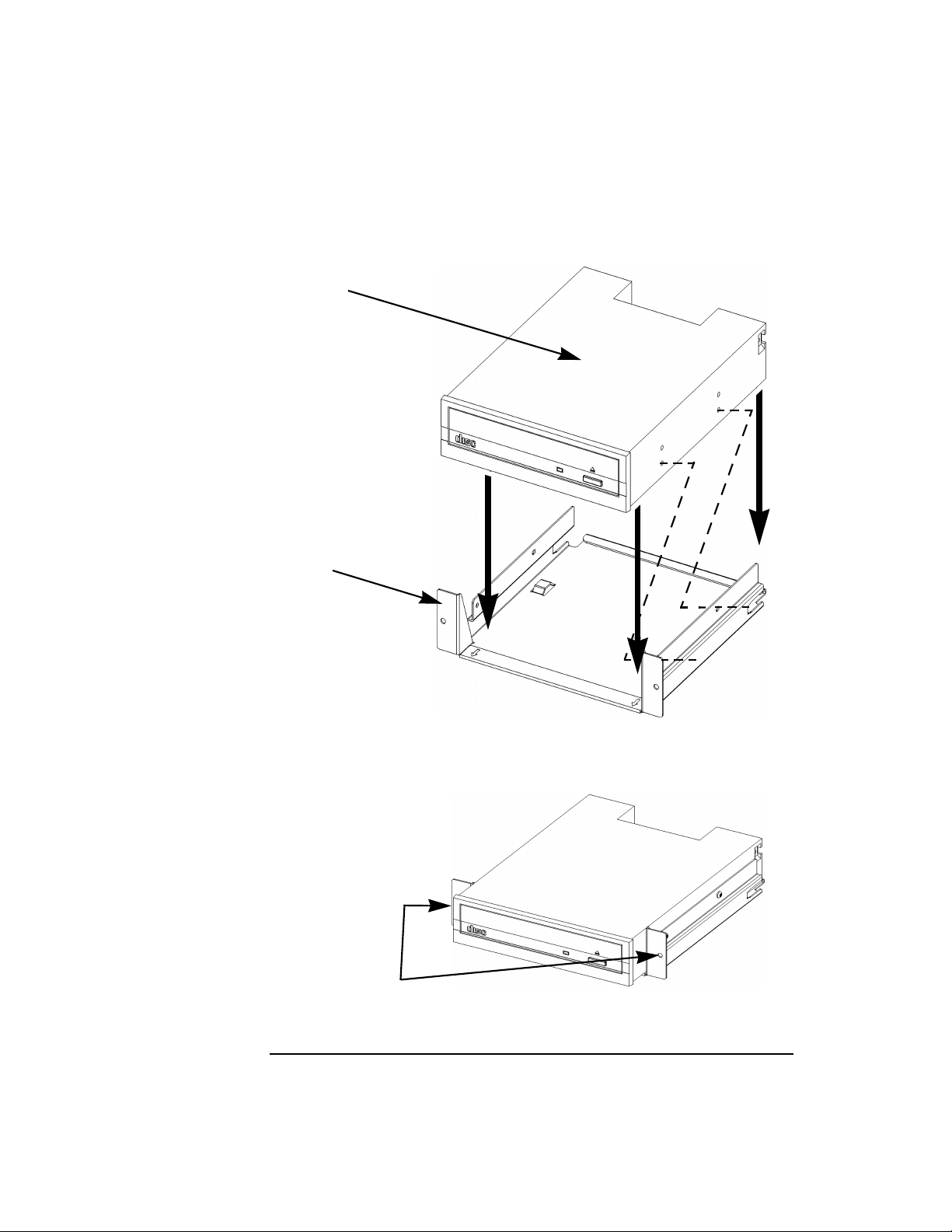
5. Install the CD drive into the bracket: the drive itself must be inserted
into the CD drive bracket as shown below, and secured by four Torx
T-10 screws (two on each side) driven into the holes indicated by the
dashed lines. These screws ship with the filler.
Chapter 2 61
Page 62
Changing Your Computer’s Hardware Configuration
CD Drive Installation
Figure 2-16 Inserting the CD Drive Into its Bracket
CD Drive
CD Drive Bracket
The assembly should now appear as follows:
Figure 2-17 The CD Drive in its Bracket
Secure the CD
drive assembly by
inserting screws here
62 Chapter2
Page 63

Changing Your Computer’s Hardware Configuration
CD Drive Installation
6. Slide the bracket, now containing the CD drive, halfway into the CD
drive bay.
7. Connect the power, audio, and ribbon cables into their respective
connectors, taking care to fold the ribbon cable neatly, so it won’t be
crushed during insertion.
8. Finish seating the CD drive bracket into the main chassis, taking
care not to pinch the cables as the CD drive is being pushed into the
bay. Insert the two screws through the front of the tray to secure the
assembly to the main chassis.
9. Replace the CD EMI cover, again taking care not to pinch the cables.
10.Replace the computer’s top panel and front panel.
11.After rebooting, use SAM (the System Administration Manager), or
the steps in the next section, to confirm that the CD drive is
recognized by the system.
Forinformation on normal usage, see the chapter“Using Your CD Drive.”
Chapter 2 63
Page 64

Changing Your Computer’s Hardware Configuration
CD Drive Installation
Verifying the CD Drive Operation
To verify that your workstation can communicate with the CD drive,
follow these steps:
1. In a terminal window, enter the following command:
/usr/sbin/ioscan -d sdisk Return
After a few moments the ioscan utility lists all of the SCSI I/O devices
it could find. The list appears similar to the following:
H/W Path Class Description
==================================================
10/0/14/0.0.0 disk TEAC CD-532E-B CDROM
10/0/15/1.6.0 disk SEAGATE ST39102LC
If ioscan does not see your CD drive it returns the following
message:
ioscan: No hardware found
2. If the system does not recognize the drive, see the Troubleshooting
chapter for hints on how to determine the problem and solve it.
64 Chapter2
Page 65

Changing Your Computer’s Hardware Configuration
DDS Drive Installation
DDS Drive Installation
NOTE Before opening the system unit to install a DDS drive, determine the
SCSI IDs currently in use on your computer, so as to avoid SCSI ID
conflicts.
To install a DDS drive, follow the steps below:
1. Using standard static-suppression practices (described in the Preface
of this document), remove the computer’s front panel, as described in
“Removing the Front Panel” on page 44, and top cover, as described
in “Opening the Top Cover” on page 46. Then remove the DDS-drive
bay’s EMI (electromagnetic interference) cover—the thin metal cover
that is snapped in place above the DDS drive bay.
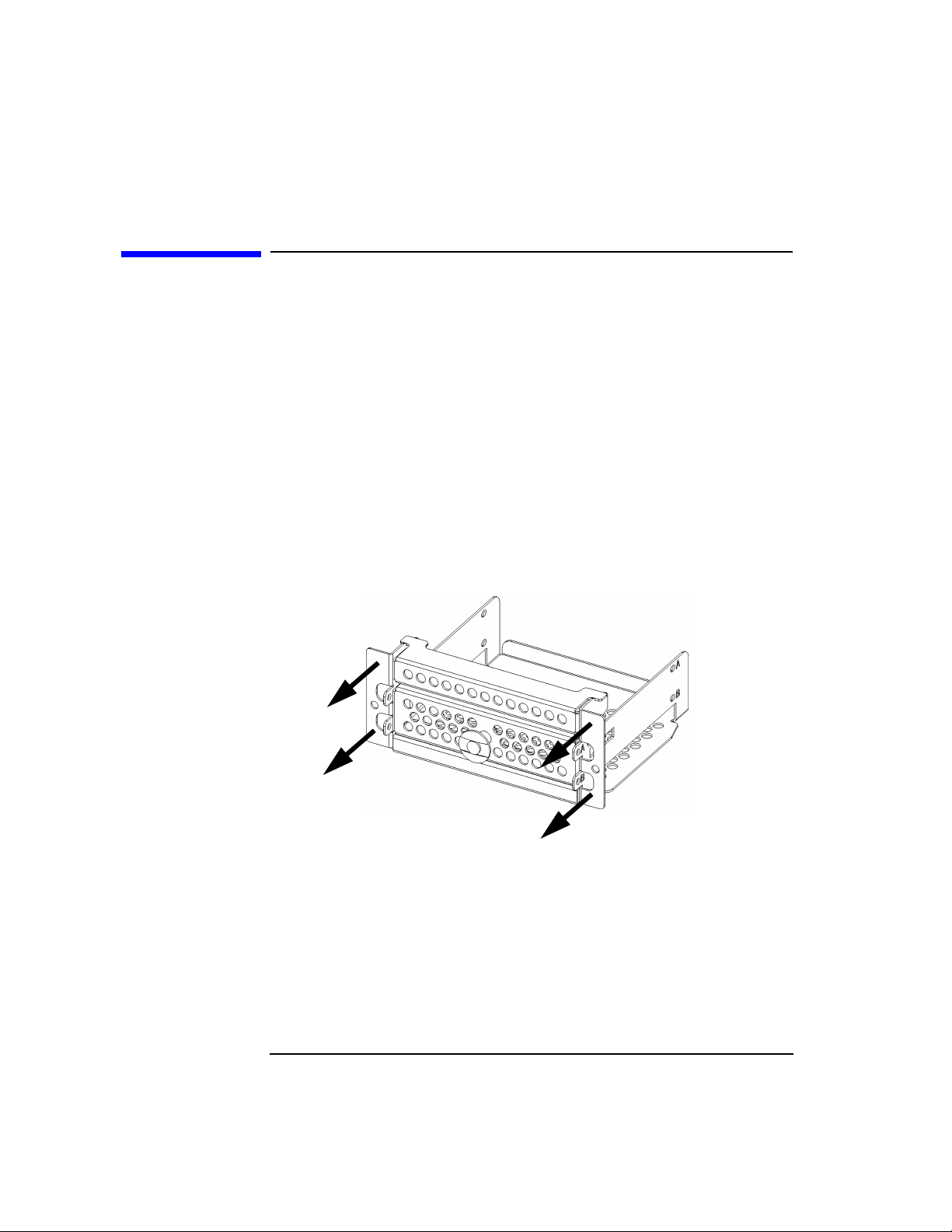
2. Remove the DDS/floppy drive bracket from the main chassis. The
bracket is referred to as the “DDS/floppy drive bracket” because the
same bracket can house either a DDS drive or a floppy drive (but not
both simultaneously).
Figure 2-18 Removing the DDS/Floppy Drive Bracket
Filler Panels
3. Remove the filler panels from the DDS drive bracket and save them
for future use. Four of the six screws will be used to secure the DDS
drive to its bracket; save the remaining two for future use.
Chapter 2 65
Page 66

Changing Your Computer’s Hardware Configuration
DDS Drive Installation
Figure 2-19 Removing the DDS/Floppy Drive Bracket
4. Install the DDS drive into the bracket: the drive itself must be
inserted into the DDS drive bracket, and secured by four Torx T-10
screws (two on each side).
Figure 2-20 The DDS Drive Installed Into the DDS/Floppy Drive Bracket
5. Connect the power and ribbon cables to the DDS drive.
6. Slide the bracket, now containing the DDS drive, into the DDS drive
bay.
66 Chapter2
Page 67

Changing Your Computer’s Hardware Configuration
DDS Drive Installation
7. Slide the bracket, now containing the DDS drive, into the DDS drive
bay. Observing—and manipulating, if necessary—from above, make
sure the drive’s ribbon cable folds neatly and compactly, and its
ferrite bead (the elongated loop of iron-containing material) does not
hinder the folding process.
8. Insert the two screws through the front of the tray to secure the
assembly to the main chassis.
9. Replace the computer’s front panel.
10.After rebooting, use SAM (the System Administration Manager), or
the steps described in the next section, to confirm that the DDS drive
is recognized by the system.
For information on normal usage, see Chapter 5 , “Using Your Digital
Data Storage (DDS) Tape Drive,” on page 103.
Verifying the DDS Tape Drive Operation
To verify that your workstation can communicate with the DDS-format
tape drive, enter the following:
/usr/sbin/ioscan -d stape
After a few moments the ioscan utility returns a message similar to the
following:
H/W Path Class Description
==================================================
10/0/15/0.3.0 tape HP C1533A
If ioscan does not see your tape drive, it will return the following
message:
ioscan: No hardware found
If the system does not recognize the drive, see Chapter 9 ,
“Troubleshooting,” on page 167, for hints on how to determine the
problem and solve it.
Chapter 2 67
Page 68
Changing Your Computer’s Hardware Configuration
Floppy Drive Installation
Floppy Drive Installation
To install a PC floppy drive into the J5000/J7000, follow the steps below:
1. Using standard static-suppression practices (described in the Preface
to this document), remove the computer’s front panel, as described
earlier in “Removing the Front Panel” on page 44, and top cover, as
described in “Opening the Top Cover” on page 46. Then remove the
floppy-drive bay’s EMI (electromagnetic interference) cover—the thin
metal cover that is snapped in place above the floppy drive bay.
2. Remove the two screws securing the DDS/floppy drive bracket to the
main chassis, and pull the bracket straight out. The bracket is
referred to as the “DDS/floppy drive bracket” because the same
bracket can house either a DDS drive or a floppy drive (but not both
simultaneously).
Figure 2-21 Removing the DDS/Floppy Drive Bracket
68 Chapter2
Page 69

Changing Your Computer’s Hardware Configuration
Floppy Drive Installation
3. Remove the filler panels from the DDS/floppy drive bracket by
removing the screws and sliding the panels back and then up, as
indicated in the illustration below. Save the larger of the two filler
panels for future use; the smaller of the two will be re-installed after
the floppy drive itself has been installed onto the bracket. Four of the
six screws will be used to secure the floppy drive to the bracket; the
other two screws will be used to re-install the smaller filler panel onto
the bracket.
Figure 2-22 Removing the DDS/Floppy Drive Filler Panels
4. Install the floppy drive into the bracket: the drive itself must be
inserted into the DDS/floppy drive bracket where the larger of thetwo
fillers had been, and secured by four Torx T-10 screws (two on each
side; the four bottom screws in the illustration above).
5. Install the smaller of the two fillers back into the bracket, atop the
floppy drive. Secure it with two remaining screws, and the assembly
should appear as follows.
Chapter 2 69
Page 70

Changing Your Computer’s Hardware Configuration
Floppy Drive Installation
Figure 2-23 Floppy Drive, Filler Installed into the DDS/Floppy Drive Bracket
6. Connect the power cable and the data (ribbon) cable to the floppy
drive.
7. Slide the bracket, now containing the floppy drive, into the floppy
drive bay. Observing—and manipulating, if necessary—from above,
make sure the drive’s ribbon cable folds neatly and compactly, and its
ferrite bead (the elongated loop of iron-containing material) does not
hinder the folding process.
8. Seat the bracket into the main chassis, again taking care not to pinch
the cables as the floppy drive is being pushed into the bay. Insert the
two screws through the front of the tray to secure the assembly to the
main chassis.
9. Replace the floppy drive bay’s EMI cover, and the computer’s top
cover and front panel.
10.After rebooting, use SAM (the System Administration Manager) to
confirm that the sioflop and siofdc floppy drivers are in the kernel.
If they are not, use SAM to add them to the kernel (after adding
drivers to the kernel, rebooting is required in order to put them to
use.
For information on normal usage, see the chapter “Using Your 3.5-Inch
Floppy Disk Drive.”
70 Chapter2
Page 71

Changing Your Computer’s Hardware Configuration
Floppy Drive Installation
Verifying the Floppy Drive Configuration
To verify that your workstation can communicate with the floppy drive,
use the ioscan command in a terminal window to see which devices are
currently in use on your system. Note that you will have to be superuser
or root to use the ioscan command.
Enter the following command at the prompt and press Enter:
/usr/sbin/ioscan -C floppy
After a few seconds, the ioscan utility lists all of the floppy disk devices
it could find. The list appears similar to the following:
H/W Path Class Description
==================================================
10/0/14/1/4.1 floppy HP_PC_FDC_FLOPPY
If ioscan does not see any SCSI drives it returns the following message:
ioscan: No hardware found
If the system does not recognize the drive, see the Troubleshooting
chapter for hints on how to determine the problem and solve it.
If the floppy driver is not configured, ioscan returns the following
message:
ioscan: Device driver floppy is not in the kernel
Chapter 2 71
Page 72

Changing Your Computer’s Hardware Configuration
Floppy Drive Installation
72 Chapter2
Page 73

3 Hot-Pluggable Hard Disk Drives
This chapter describes the hot-pluggable hard disk drives, and how to
install and remove them.
73
Page 74

Hot-Pluggable Hard Disk Drives
The Disk Drives
The Disk Drives
When reconfiguring your computer’s internal hardware, always wear a
properly grounded wrist strap to avoid damaging components.
Figure 3-1 System Unit with Front-Panel Door Open
Floppy Drive or
DDS Drive Bay
CD Drive
Power switch
System LCD
Interchangeable
hard disk drives
The above illustration shows that the four hard disk drives are accessible
simply by opening the door on the front panel (also known as the “bezel,”
pronounced “bezz-ull”); it is unnecessary to remove the entire panel.
From a hardware point of view, these four disk drives are
interchangeable: one drive will work as well as any other in any given
slot. And, you need not set the SCSI bus addresses for these drives: their
74 Chapter3
Page 75

Hot-Pluggable Hard Disk Drives
The Disk Drives
positions in the slots, not switches on the drives themselves, define the
SCSI address for each drive. These addresses are labelled on the chassis.
Finally, these hard drives are hot-pluggable: that is, you do not need to
power down the entire machine to remove or insert a hard disk drive.
CAUTION However, from a software point of view, there are two restrictions on the
interchangeability of these drives:
• The boot device—that disk drive that contains the operating
system—must be in drive bay 6, the uppermost bay.
• The boot device must not be removed while the system is running.
For details, see the section “The Hot-Plug Process” later in this chapter.
Chapter 3 75
Page 76

Hot-Pluggable Hard Disk Drives
The Disk Drives
Removing a Hard Disk Drive
The instructions for removing a disk drive from the J5000/J7000 are
printed on the front panel, and are visible when the panel door is opened,
as shown in the detail below.
CAUTION If you are removing a hard disk drive while the system is running, you
must perform the operations outlined in “The Hot-Plug Procedure” on
page 83 before the physical removal of the drive, or data corruption is
likely to occur.
Figure 3-2 Removing a Hard Disk Drive
The instructions are also printed here for your convenience:
1. Identify the drive to be removed, and make sure it is not currently in
use. If the machine is to remain powered up, see the section “The
Hot-Plug Procedure” on page 83 for the proper preparations.
2. Push the plastic retaining tab to the right, to release the drive-tray’s
handle. Pull the handle on the drive to unseat it from its power and
data connections.
76 Chapter3
Page 77

Hot-Pluggable Hard Disk Drives
The Disk Drives
3. Wait about 30 seconds for the drive to spin down (handling of a disk
drive while it is still spinning can cause disk damage and/or loss of
data).
4. Carefully pull the drive straight out.
If you also need to remove the disk drive from the disk-drive tray—to
replace a faulty drive, for example—remove the four screws that secure
the drive to the tray. These screws go through rubber grommets; leave
the grommets in place as you remove the screws.
Putting a Disk Drive into its Tray
When you receive and unpack a new disk drive, it will not include the
tray that is needed in order to insert it into your J5000/J7000 computer;
these trays are already in your computer’s disk-drive bays. You will need
to assemble the disk drive into its tray before you can slide the disk drive
and tray assembly into the computer and expect its connections to be
made correctly.
1. Unpack the new disk drive, avoiding both mechanical and electrical
shocks; never let it drop onto the floor or onto a desk—always set it
down gently—and observe ESD (electrostatic discharge) precautions,
as described in the Preface of this document.
CAUTION A drop of just a few inches onto a hard surface such as a desk or the floor
can generate large accelerations (hundreds of gees), which may damage
the device.
2. Unlock (if necessary) and open the door on the front of the computer.
Remove the disk-drive tray from the slot into which you will insert
the new drive. To remove the disk-drive tray, release the hook that
locks the drive tray’s release lever into place (see Figure 3-3, below),
and pull the release lever toward you. The tray will come out.
3. If a disk drive was already in the tray (for example,if you’re replacing
a faulty drive), remove the four screws securing the drive to the tray,
and pull the drive straight up out of the tray. If the tray never had a
Chapter 3 77
Page 78

Hot-Pluggable Hard Disk Drives
The Disk Drives
drive in it, the four screws required to secure the drive to the tray are
stored in two tabs on the tray (see illustration below). Remove these
four screws from the storage tabs.
Figure 3-3 Installing a Hard Disk Drive into its Tray
Screw-storage tab
Release lever
Grommets (do not remove)
Screw-storage tab
Release hook
4. Insert these four screws through the rubber grommets and into the
corresponding holes in the disk drive, and tighten them with a T15
Torx driver. There are four rubber grommets, although only two are
visible in the illustration above.
NOTE Do not remove the grommets; if they are removed, the drive would not be
held securely in the tray and may be damaged as a result.
Once the disk drive is installed into the drive tray, the assembly can be
inserted into the desired hard-drive slot.
78 Chapter3
Page 79

Hot-Pluggable Hard Disk Drives
The Disk Drives
Inserting a Disk Drive
To insert a drive, the procedure is virtually identical to the “removing”
steps above, except in the reverse order:
1. Carefully push the drive, which is already in its tray, straight into the
desired slot, making sure the drive-tray’s handle is pulled away from
the front surface of the tray.
2. When the drive-tray’s handle can engage the hooks on the left edge of
the slot, push the right end of the handle flush to the front of the
drive; this will seat the drive into its power and data connections.
When the handle gets flush to the front of the tray, it should engage
the retaining tab with a noticeable click.
NOTE The drive tray will not go all the way into the slot if the handle has
already been folded flat against the front of the tray. Push the drive tray
into the slot firmly, and then push the handle flat against the front of the
tray.
Chapter 3 79
Page 80

Hot-Pluggable Hard Disk Drives
The Hot-Plug Process
The Hot-Plug Process
The physical aspect of inserting and removing a disk drive, as discussed
in the previous section, is straightforward. However, the operating
system must be prepared for the insertion or removal of a disk, or
unexpected and harmful effects may occur.
There is a significant difference between the terms “hot-pluggable” and
“hot-swappable.” Hot swapping happens at the device level; that is, a
hot-swappable device manages insertion/removal on its own without
assistance from HP-UX commands. The disk drives in the J5000 and
J7000 are not hot-swappable; they are merely hot-pluggable. Thus, a
manual software procedure must be done in order to safely remove or
insert disk drives while the system is running.
The reason the hot-plug process exists is that you might need to replace
a defective disk drive in a high-availability system while it is running.
Replacing a Failed Disk Drive
In the context of replacing a failed disk drive, the system administrator
must determine which disk has failed. Depending on how the system was
set up, the identity of the failed drive may or may not be obvious. This
determination may be done in either of two ways:
• Tracking the error messages written by the LVM (Logical Volume
Manager) to the system console and/or a log file. For information on
LVM commands, see the man pages for vgdisplay, vgchange,
lvreduce, vgcfgrestore, lvlnboot, lvextend, etc.
• If installed, run the diagnostic utility Support Tool Manager (xstm)to
determine disk malfunction.
The removal of a defective disk drive from an active file system is
supported through LVM commands if hot-pluggable disks have been
configured into the HP-UX file system with LVM. To provide high
availability, without impact to users, the disks must also be configured as
mirrored disks. Disk-mirroring is accomplished through use of the
MirrorDisk/UX software (HP part number B2491A); for information on
classes, see http://www.hp.com/education/courses/h6285s.html.
No graphical user interface is currently offered through the System
Administration Manager (SAM) for doing the required LVM commands,
80 Chapter3
Page 81

because manipulation of the LVM requires specialized knowledge that
only experienced system administrators are expected to have (see below
for details).
Hot-Plug Example
The following example describes a particular system problem where the
solution is to replace a hot-plug disk module.
Volume group /dev/vg00 contains the three disks, with the logical
volume configuration as shown:
Table 3-1 Example Configuration
Volume Description Volume Description Volume Description
Logical Volume 1 Logical Volume 3 Logical Volume 4
Logical Volume 2 Logical Volume 4 Logical Volume 5
Logical Volume 3 Logical Volume 5
Hot-Pluggable Hard Disk Drives
The Hot-Plug Process
hardware address 10/0/12/0.0 10/0/13/0.0 10/0/14/0.0
device file (/dev/dsk/) c2t6d0 c2t5d0 c2t4d0
Chapter 3 81
Page 82

Hot-Pluggable Hard Disk Drives
The Hot-Plug Process
The system problem for this example is that the disk at hardware
address 10/0/14/0.0 has a head crash, and as a result, is unusable. The
steps described in the Hot-Plug Procedure section below outline a
method that can be used to recover from this state.
1. All of the replaced disk’s in-use extents must belong to mirrored
logical volumes which were created with the “strict” option (-s); see
the documentation for MirrorDisk/UX.
2. You must have an up-to-date configuration backup file. This is done
automatically each time an LVM command changes LVM
configuration.
The default backup file’s path is:
/etc/lvmconf/base_vg_name.conf
3. The replacement disk must be the same product ID as the replaced
one.
NOTE HP often uses different manufacturers for disks having the same product
number. The hot-plug manual procedure will not update the disk driver’s
internal information to that of the replaced disk.
The replacement disk will have the same capacity and block size as
the defective disk because they have the same product number. The
only field that could be incorrect is the string specifying the vendor’s
name. This will not affect the behavior of the LVM. If it is desired to
update the manufacturers’ name, the disk’s volume group must be
deactivated and reactivated. See the HP-UX System Administration
Tasks manual for details.
82 Chapter3
Page 83

Hot-Pluggable Hard Disk Drives
The Hot-Plug Process
The Hot-Plug Procedure
These are the steps required to properly hot-plug a disk drive:
Step 1
• Check if the LVM found the physical volume to be defective when the
volume group was activated.
• The “vgchange -ey” would have printed the following message on the
console:
WARNING:
VGCHANGE:WARNING: COULDN’T ATTACH TO THE VOLUME GROUP
PHYSICAL VOLUME “/DEV/DSK/cXtXdX”
THE PATH OF THE PHYSICAL VOLUME REFERS TO A DEVICE THAT
DOES NOT EXIST, OR IS NOT CONFIGURED INTO THE KERNEL.
• If the status of the“vgchange -v vg02” is unknown, you may checkif
this occurred by doing a vgdisplay command:
vgdisplay 〈VG name〉
For our example:
vgdisplay /dev/vg00
• If the disk was defective at vgchange time, the following messages
will be printed one or more times.
WARNING:
VGDISPLAY: WARNING: COULDN’T QUERY PHYSICAL VOLUME
“/DEV/DSK/cXtXdX”
THE SPECIFIED PATH DOES NOT CORRESPOND TO PHYSICAL VOLUME
ATTACHED TO THE VOLUME GROUP.
VGDISPLAY: WARNING: COULDN’T QUERY ALL OF THE PHYSICAL
VOLUMES
• If you see these messages, the disk was defective at the time the
volume group was activated.
Otherwise, your disk became defective after the vgchange and you must
continue with step 2 of this procedure.
Chapter 3 83
Page 84

Hot-Pluggable Hard Disk Drives
The Hot-Plug Process
Step 2
• Reduce any logical volumes that have mirror copies on the faulty disk
so that they no longer mirror onto that disk (note the -A n option):
lvreduce -m 0 -A n 〈LV name〉 /dev/dsk/cXtXdX
(for 1-way mirroring)
or
lvreduce -m 1 -A n 〈LV name〉 /dev/dsk/cXtXdX
(for 2 way mirroring)
For our example:
lvreduce -m 0 -A n /dev/vg00/lvol4 /dev/dsk/c2t4d0
lvreduce -m 0 -A n /dev/vg00/lvol5 /dev/dsk/c2t4d0
Step 3
• Replace the faulty disk. Refer to the instructions earlier in this
chapter for details on how to replace the disk.
•Doanioscan on the replaced disk to insure that it is accessible and
also as a double check that it is a proper replacement.
For our example:
ioscan /dev/dsk/c2t4d
Step 4
• Restore the LVM configuration/headers onto the replaced disk from
your backup of the LVM configuration:
vgcfgrestore -n 〈volume group name〉 /dev/rdsk/cxtxdx
where x is the logical unit number of the disk that has been replaced.
For our example:
vgcfgrestore -n /dev/vg00 /dev/rdsk/c2t4d0
Step 5
• Attach the new disk to the active volume group with the vgchange
command.
vgchange -a y 〈volume_group_name〉
For our example:
vgchange -a y /dev/vg00
84 Chapter3
Page 85

Hot-Pluggable Hard Disk Drives
The Hot-Plug Process
Step 6
• If this disk is not a mirror of a root disk, then skip this step.
• Run the mkboot command. For our example:
mkboot /dev/rdsk/c2t4d0
• Run lvlnboot -R to relink the replaced disk into the Boot Data
Reserved Area of all the Physical Volumes in the Volume Group.
lvlnboot -R
Step 7
• Run lvextend to extend the mirrors back onto the replaced disk.
This may take several minutes, as it will have to copy all the data
from the original copy of the data to the mirrored extents. The logical
volume(s) are still accessible to users’ applications during this
command.
lvextend -m 1 〈LV name〉 /dev/dsk/cxtxdx
or
lvextend -m 2 〈LV name〉 /dev/dsk/cxtxdx (3-way mirroring)
For our example:
lvextend -m 1 /dev/vg02/vg02 /dev/dsk/c3t5d0
lvextend -m 1 /dev/vg00/lvol4 /dev/dsk/c2t4d0
lvextend -m 1 /dev/vg00/lvol5 /dev/dsk/c2t4d0
At this stage, your system should be fully functioning; use xstm to verify.
Chapter 3 85
Page 86

Hot-Pluggable Hard Disk Drives
Checking the SCSI IDs
Checking the SCSI IDs
To determine which SCSI IDs are currently in use on your system, use
the ioscan command in a terminal window. Note that you will need to be
superuser (root) in order to use the ioscan command.
Here are the steps necessary for determining SCSI IDs:
1. In a terminal, type the following at the shell prompt and press Enter:
/usr/sbin/ioscan -f
After a few moments, the ioscan utility lists all of the I/O devices it
could find. The list appears similar (but likely not identical) to the
following:
Class I H/W Path Driver S/W State H/W Type Description
=============================================================================
bc 0 root CLAIMED BUS_NEXUS
bc 1 10 ccio2 CLAIMED BUS_NEXUS I/O Adapter
ba 0 10/0 lba CLAIMED BUS_NEXUS PCI Bus Bridge - lba
graphics 0 10/0/1/0 graph3 CLAIMED INTERFACE PCI(103c1005) -- 1
lan 0 10/0/12/0 btlan3 CLAIMED INTERFACE PCI(10110019)
audio 0 10/0/13/0 audio CLAIMED INTERFACE Built-in Audio
ext_bus 0 10/0/14/0 side CLAIMED INTERFACE IDE
target 0 10/0/14/0.0 tgt CLAIMED DEVICE
disk 0 10/0/14/0.0.0 sdisk CLAIMED DEVICE TEAC CD-532E-B CDROM
target 1 10/0/14/0.7 tgt CLAIMED DEVICE
ctl 0 10/0/14/0.7.0 sctl CLAIMED DEVICE Initiator
ba 1 10/0/14/1 superio CLAIMED BUS_NEXUS PCI Core I/O Adapter
tty 0 10/0/14/1/1 asio0 CLAIMED INTERFACE Built-in RS-232C
tty 1 10/0/14/1/2 asio0 CLAIMED INTERFACE Built-in RS-232C
ext_bus 1 10/0/14/1/3 SCentIf CLAIMED INTERFACE Built-in Parallel Interface
pc 0 10/0/14/1/4 siofdc UNCLAIMED UNKNOWN Built-in Floppy Drive
usb 0 10/0/14/2 hcd CLAIMED INTERFACE Built-in USB Interface
usbhub 0 10/0/14/2.1 hub CLAIMED DEVICE USB Root Hub
usbhid 0 10/0/14/2.1.2 hid CLAIMED DEVICE USB HID Kbd(0)
usbhid 1 10/0/14/2.1.3 hid CLAIMED DEVICE USB HID Mouse(1)
ext_bus 2 10/0/15/0 c720 CLAIMED INTERFACE Ultra Narrow Single-Ended
SCSI
target 2 10/0/15/0.7 tgt CLAIMED DEVICE
ctl 1 10/0/15/0.7.0 sctl CLAIMED DEVICE Initiator
ext_bus 3 10/0/15/1 c720 CLAIMED INTERFACE Ultra2 Wide LVD SCSI
target 3 10/0/15/1.6 tgt CLAIMED DEVICE
disk 1 10/0/15/1.6.0 sdisk CLAIMED DEVICE SEAGATE ST39102LC
target 4 10/0/15/1.7 tgt CLAIMED DEVICE
ctl 2 10/0/15/1.7.0 sctl CLAIMED DEVICE Initiator
ba 2 10/1 lba CLAIMED BUS_NEXUS PCI Bus Bridge - lba
ba 3 10/2 lba CLAIMED BUS_NEXUS PCI Bus Bridge - lba
ext_bus 4 10/2/3/0 c720 CLAIMED INTERFACE Ultra Wide SCSI
target 5 10/2/3/0.7 tgt CLAIMED DEVICE
ctl 3 10/2/3/0.7.0 sctl CLAIMED DEVICE Initiator
86 Chapter3
Page 87

Hot-Pluggable Hard Disk Drives
Checking the SCSI IDs
ba 4 10/4 lba CLAIMED BUS_NEXUS PCI Bus Bridge - lba
ba 5 10/6 lba CLAIMED BUS_NEXUS PCI Bus Bridge - lba
graphics 1 10/6/7/0 graph3 CLAIMED INTERFACE PCI(103c1008)
processor 0 32 processor CLAIMED PROCESSOR Processor
processor 1 34 processor CLAIMED PROCESSOR Processor
memory 0 49 memory CLAIMED MEMORY Memory
2. You can determine which SCSI IDs are currently in use by looking
under the “H/W Path” heading. In the example display, the H/W Path
for the built-in SCSI interface is 8/16/5. For devices connected to the
built-in SCSI bus, such as disks, the fourth number is the SCSI ID for
that device. For example, the listing 8/16/5.2.0 tells you that there
is a SCSI device (a disk) currently using ID 2 on the SCSI bus.
NOTE Never use SCSI address 7 for any device. Address 7 is reserved for the
SCSI controller.
Using Device Files
Device files are special files that tell your system which pathway to use
through the system hardware when communicating with a specific
device and what kind of device it is.
NOTE The device file names depend on the naming conventions of your
particular system.
To determine what device files are available for use with your disk drive,
use the following procedure:
1. In a terminal window, become root and type the following command
at the prompt and press Enter:
sam
The System Administration Manager (SAM) window opens.
2. Double click on the Disks and File Systems icon. The Disk and File
Systems window opens.
3. Click on a desired disk drive in the list of disk devices to select it.
4. Select the Actions menu and then select the menu item View More
Chapter 3 87
Page 88

Hot-Pluggable Hard Disk Drives
Checking the SCSI IDs
Information. A window opens with a list of information for the disk
drive, including the device files.
88 Chapter3
Page 89

4 Using Your CD Drive
89
Page 90

Using Your CD Drive
Operating the CD Drive
Operating the CD Drive
This section describes how to use your CD drive.
NOTE Be sure you read and understand the information on mounting and
unmounting CDs before you begin using your CD drive.
This chapter provides an overview of the optional CD drive and media,
and describes how to install and use the CD drive.
NOTE Some procedures in this chapter require you to log in as root. If you
cannot log in as root, contact your system administrator.
In this chapter, we use the terms “CD” and “CD drive” rather than
“CD-ROM” and “CD-ROM drive” because the CD drives used in the
J5000 and the J7000 can read the original CD-ROM disks, plus CD-R
disks and the newer CD-RW disks (also called “CD-RAM” because they
are rewritable). Thus, since not all CDs are ROMs any longer, that
portion of the term has been dropped.
The CD drives also are multisession-capable.
Note that this chapter assumes you are running HP-UX 10.20 with the
HP-UX 10.20 Workstation ACE (June 1999).
90 Chapter4
Page 91
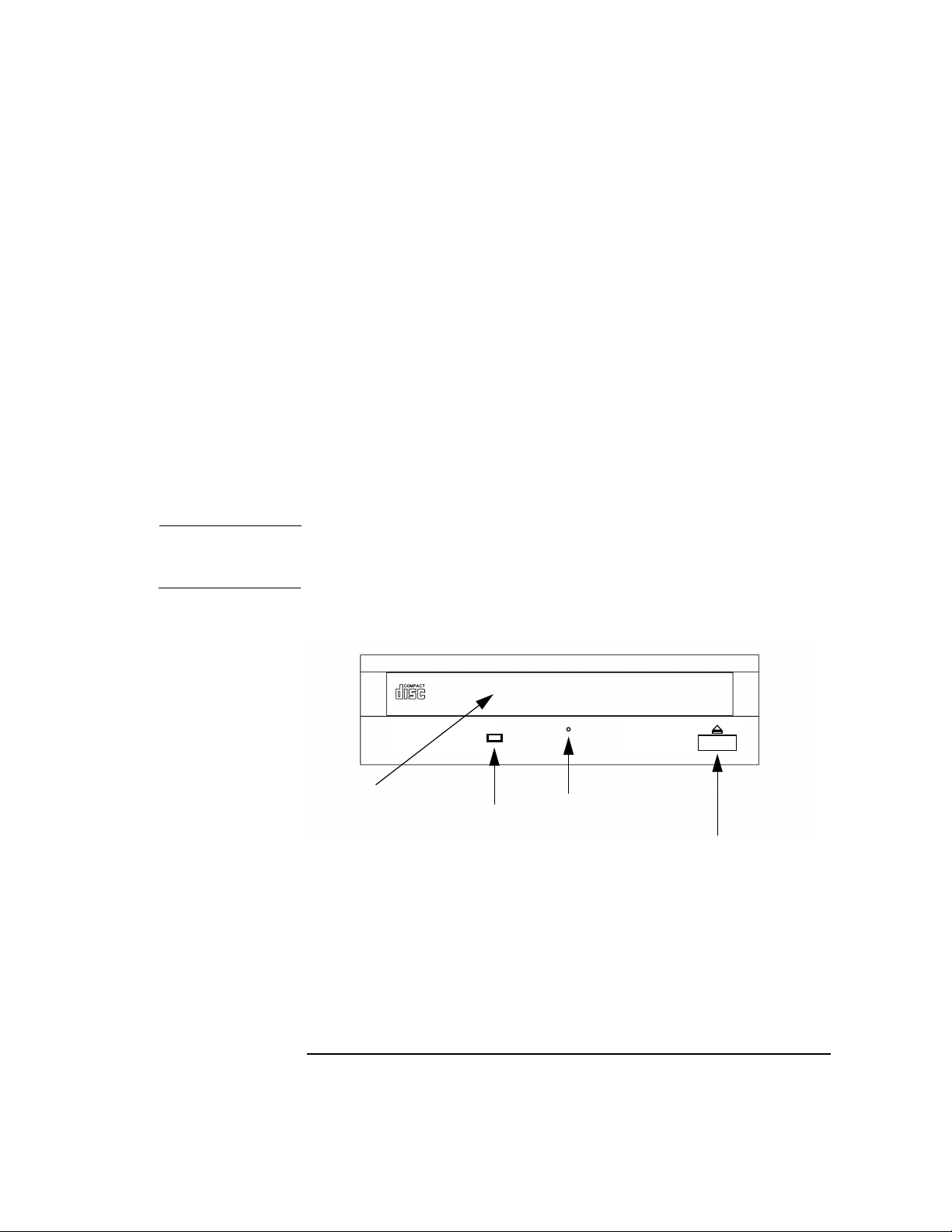
Using Your CD Drive
Operating the CD Drive
The CD Drive
The CD drive is a random-access read-only mass storage device that uses
removable CDs.
The drive supports the ISO 9660 and High Sierra format standards. You
can access information from the drive like any other disk drive, except
that you cannot write to the drive. The drive contains a semiconductor
laser for reading data optically, and includes an embedded controller
with an ATAPI interface.
Controls and Features
The figure below and the subsequent table illustrate and describe the
operating controls and features of the CD drive.
NOTE The Busy Indicator, Emergency Eject Hole, and Eject Button may not be
in exactly the locations indicated in the illustration below.
Figure 4-1 The CD Drive’s Controls
CD Tray
Busy
Indicator
Chapter 4 91
Emergency
Eject Hole
Eject
Button
Page 92

Using Your CD Drive
Operating the CD Drive
Table 4-1 CD Drive Controls and Indicators
Control/Feature Purpose
Busy Indicator The Busy Indicator blinks during various operations
of the drive.
Eject Button Press the Eject Button to open the disk tray to insert or
remove a disk. When the drive is in use, you must
press the eject button for more than one second to
open the disk tray.
Emergency Eject
Hole
CD Tray The CD Tray holds the CD. This CD drive does not
NOTE There is neither a volume control nor a headphone jack on the front of
the CD drive. To listen to an audio CD, use the headphone jack on the
rear panel, and control the sound volume via software called “xmcd” (for
details, see “Audio Control for the CD Drive” on page 95).
By inserting the end of a straightened paperclip, you
can open the disk tray when the workstation is
powered down.
use a CD caddy.
92 Chapter4
Page 93

Using Your CD Drive
Operating the CD Drive
CD Media
CDs are 120mm (4.7 in.) in diameter, and use one data surface with a
capacity of approximately 600 megabytes. The data surface contains pits
and flat spots arranged in a continuous spiral track, which is read at a
constant linear speed (and hence a variable rotational speed). Originally,
all CDs were CD-ROMs; i.e., you could access files and data stored on
them, but could not write files or data to them; it was indeed a CD-ROM;
i.e., Read-Only Memory. Since then, writable, and even rewritable CDs
(“CD-RAMs”) have come available; your workstation can read any of
these types of CDs, but you cannot write CDs with your workstation
without additional hardware and software.
CD data disks are identical to audio compact disks (CDs) except that
they store computer data and information.
CAUTION Handle CDs by the edges only. Always be sure a CD is either in the CD
drive or its protective case or envelope when not in use. If you must set it
down when it is not in its protective case or envelope, lay it down with
the shiny side up (labelled side down); this will lessen the chance of
scratch damage to the more-sensitive data side. Putting CDs back into
their cases or envelopes will lessen the chance of exposing the disk
surface to dust, fingerprints, and objects that could scratch the CD.
These factors will reduce the reliability of the read head in the CD drive.
Caring for CDs
Observe the following guidelines to help prevent data loss and prolong
the life of your CDs and drive:
• Use CDs in a clean environment to prevent dust particles from
scratching disk surfaces.
• Store CDs in a cool, dry place to prevent moisture and heat damage.
• Don’t try to clean the surface of a CD with cleaning solvents, as some
cleaning solvents may damage the disk.
NOTE You must mount a CD after loading it into the drive. Refer to “Mounting
and Unmounting a CD” on page 98 for instructions on mounting a CD.
Chapter 4 93
Page 94

Using Your CD Drive
Operating the CD Drive
Loading and Unloading a CD in the disk Tray
This subsection describes how to load or unload a CD in the CD drive.
Loading a CD
This CD drive has an automatic loading/ejecting feature. To load a disk
in the CD drive, follow these steps:
1. Check that the workstation is powered on.
2. To open the disk tray, press and release the Eject button on the CD
drive.
3. Hold the disk by the edges with the label side up and place it in the
disk tray.
4. To close the disk tray, push the Eject button again, as it also serves to
close the tray.
Unloading a CD
You must unmount the disk before you eject it from the drive. Unmount
the CD, using either the umount command or the instructions in
“Unmounting a CD Using SAM” on page 100. Perform the following
steps to unload a disk from the CD drive:
1. Press the eject button to eject the disk tray from the drive. If the drive
is in use, you must press the eject button for more than one second to
eject the disk tray.
2. Wait until the drive has fully ejected the disk tray. Remove the disk
from the tray. Be careful to touch only the edges of the disk.
3. To close the disk tray, push the Eject button, as it also serves to close
the tray
94 Chapter4
Page 95

Using Your CD Drive
Audio Control for the CD Drive
Audio Control for the CD Drive
The audio controls for your CD drive are provided through the xmcd
utility. This is a third-party CD player utility that runs on an X windows
system using the Motif graphical user interface. The xmcd utility is not
supported by Hewlett-Packard, and it is oneof many audio controllers for
CD drives available in the marketplace. Since the xmcd utility is not a
part of HP-UX, you will need to download it off the web using your web
browser and this URL:
http://metalab.unc.edu/tkan/xmcd
Installing the xmcd Utility
Here is the procedure for downloading the xmcd utility to your system:
1. Log in as root.
2. Type the previously given URL into the entry box on your web
browser and press Enter.
3. Select the menu item labeled Downloads found on the xmcd
homepage.
4. Scroll down to the section “Select your platform:” on the Downloads
web page and select the item labeled “HP-UX 9.x and later (HP
PA-RISC).”
5. Wait for a few seconds for the Save As... pop-up window to appear. In
this window, click in the Selection entry box and type the following
path and file name:
/tmp/xmcdbin.tar.gz
Next, click the OK button. This completes the download of xmcd to
your system.
6. Follow the instructions in the section “Instructions to unpack xmcd
binary” found on this Binary Downloads web page. This will
complete the installation of the xmcd utility.
Chapter 4 95
Page 96

Using Your CD Drive
Audio Control for the CD Drive
Using the xmcd Utility
The instructions in the section assume that you are using the HP-UX
10.20 operating system and the Workstation Additional Core
Enhancements (ACE) for HP-UX 10.20 (June 1999) with the HP CDE
interface. The xmcd utility must also be installed on your system. See the
section “Installing the xmcd Utility” above.
To load and play an audio CD, follow the steps in this procedure.
1. Load the audio CD. See the section “Loading a CD” in this chapter.
2. Insert the headphone plug into the headphone jack located on the
back of your system unit.
Microphone
Headphone
Line Out
Line In
3. Double-click on the Audio icon located on your HP CDE control
panel.
Audio Icon
96 Chapter4
Page 97

Using Your CD Drive
Audio Control for the CD Drive
4. Click on the Monitoring checkbox in the Audio window to select it.
Then select the Output menu and click on the Headphones item in
the menu list. In the File menu select the item Close, this will close
the Audio window and save your settings.
5. Start the utility by typing xmcd at the prompt and pressing Enter.
“Play/Pause” Button
“Eject” Button
“Help” Button
Keypad
“Stop” Button
Now that you have your audio CD player started, put on your
headphones and press the Play button to listen to the audio CD. Note
that pressing the Help button will give you information on how to use
the rest of the CD player’s buttons.
Chapter 4 97
Page 98

Using Your CD Drive
Mounting and Unmounting a CD
Mounting and Unmounting a CD
In normal system use—i.e., other than installing the operating system or
firmware—you must first mount a CD in order to access information on it
(this applies to file system information only: if you wish to load a music
CD, you would not need to mount the disk). Mounting a disk with file
system information on it gives the disk a pathname that allows your
workstation to communicate electronically with it. Similarly, you must
unmount the CD before removing it from the drive.
CAUTION To use a CD as a mounted file system, you must mount the CD every
time you load it into the drive. You must also unmount the CD every time
you unload it from the drive. Failure to mount or unmount a disk can
cause a system error condition that can require rebooting the system.
To mount a CD as a file system, you can use the mount command (see the
man page for mount for details). Or, you can use SAM (the System
Administration Manager) if you prefer; the instructions for using SAM to
mount and unmount CDs are in the next section.
If your workstation is running HP CDE, follow these instructions to
mount and unmount a CD as a file system. If you’re using something
other than HP CDE, use the instructions for mounting and unmounting
a CD that come with that product. For more information on configuring
your CD drive, see the System Administration Tasks manual or online
help.
The procedures in this chapter require you to log in as root. If you
cannot log in as root, contact your system administrator.
98 Chapter4
Page 99

Using Your CD Drive
Mounting and Unmounting a CD
Mounting a CD Using SAM
Use the following procedure to mount a CD:
• Log in as root. If you need information on logging in or setting up a
user account, see Using Your HP Workstation.
• Load the CD into the disk tray and push the Eject button, or gently
push the tray a short distance into the drive; the drive will then close
the rest of the way by itself.
• In a terminal window, enter the following command:
sam Enter
• The System Administration Manager window opens, showing several
icons, one of which looks like this:
• Double-click on the Disks and File Systems icon, and the Disks and
File Systems
which looks like this:
• Double-click the File Systems icon, and a window containing a list of
mounted file systems appears. The following screen message appears:
Scanning the system’s hardware...
The File Systems window opens, containing a list of drives currently
mounted on this system.
• From the Actions menu, select Add a Local File System, and submenu
Not Using Logical Volume Manager.
Chapter 4 99
window appears, showing several more icons, one of
Page 100

Using Your CD Drive
Mounting and Unmounting a CD
• The Select a Disk to Add... window opens with a list of unused
mass-storage devices. Highlight the CD device containing the CD you
want to mount.
• Click on OK.
• The Add CD-ROM Disk window opens. Enter the desired mount point
(the directory under which the CD’s contents will appear in your
entire file system) and click on OK. A typical CD mount point is
/dev/CD, although you can mount it wherever you want. If the
directory you specify does not yet exist, SAM will create it for you.
• The following screen message appears:
Mounting file system...
Now you can access the CD as you would any other mounted file system.
Unmounting a CD Using SAM
Use the following procedure to unmount a CD:
NOTE Before you unmount a CD, make sure that your working directory (the
directory you’re currently “in”) is not set to any directory on the CD—this
goes for all shell windows. If you attempt to unmount a file system when
one or more working directories are set somewhere in the file system
you’re trying to unmount, you’ll get an error message something like
this:
cannot unmount /dev/CD: device busy
Toavoid this error message, simply cd to some directory that is known to
not be in the file system you want to unmount; for example, the root
directory / or your home directory. Again, make sure you do this for all
shell windows.
1. Log in as root. If you need information on logging in or setting up a
user account, see Using Your HP Workstation.
2. In a terminal window, enter the following command:
sam Return
The System Administration Manager window opens, showing several
100 Chapter4
 Loading...