

Page 1

HP VISUALIZE C3600 UNIX® Workstations
PA8600
Upgrade Instructions
Manufacturing Part Number: A5997-90000
Edition E1299
© Copyright 1999 by Hewlett-Packard
Page 2

Notice
The information contained in this document is subject to change without
notice.
Hewlett-Packard assumes no responsibility for the use or reliability of its
software on equipment that is not furnished by Hewlett-Packard.
This document contains proprietary information that is protected by
copyright. All rights reserved. No part of this document may be
photocopied, reproduced or translated to another language without the
prior written consent of Hewlett-Packard Company.
Hewlett-Packard Warranty Statement
Refer to Warranty&SupportforyourHPWorkstation for warranty terms
applicable to your Hewlett-Packard product and replacement parts.
Restricted Rights Legend
Use, duplication, or disclosure by the U.S. Government Department of
Defense is subject to restrictions as set forth in paragraph (b)(3)(ii) of the
Rights in Technical Data and Software clause in DFARS 252.227.7013.
© Copyright 1999 Hewlett-Packard Company. All Rights Reserved.
This document contains proprietary information that is protected by
copyright. All rights are reserved. No part of this document may be
photocopied, reproduced or translated to another language without the
prior written consent of Hewlett-Packard Company.
2
Page 3

UNIX is a registered trademark in the United States of America and
other countries, licensed exclusively through X/Open Company Limited.
© Copyright 1980, 1984 AT&T, Inc.
© Copyright 1979, 1980, 1983 The Regents of the University of
California.
This softwareanddocumentationisbasedinpartontheFourth Berkeley
Software Distribution under license from the Regents of University of
California.
3
Page 4

4
Page 5

1 Getting Started
The following important information must be adhered to for proper
removal and replacement of all Hewlett-Packard parts.
5
Page 6

Getting Started
CAUTION This upgrade process should be performed by experienced hardware
users only.
6 Chapter1
Page 7

Getting Started
Safety Warnings
Safety Warnings
WARNING Removing the device cover may expose sharp edges in the
equipment chassis. To avoid injury, use care when installing
customer add-on devices.
NOTE Before performing removal/replacement procedures, position the
workstation on a cushioned flat, stable surface, such as a table top or
workbench.
NOTE Installing the recommended HP replacement part in your B1000/C3000
workstation does not affect the regulatory and safety classifications or
approvals listed in the original owner’s guide.
Electrostatic Discharge (ESD) Precautions
To prevent damage to the B1000/C3000 workstation, observe all of the
following ESD precautions while performing removal and replacement
procedures:
• Remove all ESD-generating materials from the work area in which
you will remove and replace the workstation field replaceable unit(s).
• Open the ESD materials provided with the replacement part kit.
Unfold the black conductive sheeting (antistatic mat) and place it
under a corner of the workstation.
• Wear a static strap to ensure that any accumulated electrostatic
charge is discharged from your body to ground. Attach the
static-grounding wrist strap by following the instructions on the
package. Attach the sticky end of the wrist strap to bare metal on the
rear panel of the workstation.
• Connect all equipment together, including the static-free mat, static
Chapter 1 7
Page 8

Getting Started
Safety Warnings
strap, clips attached to the wrist strap, nodes, and peripheral units.
• Keep uninstalled printed circuit boards in their protective antistatic
bags.
• Once you have removed printed circuit boards from their protective
antistatic bags, handle the printed circuit boards by their edges only.
8 Chapter1
Page 9

Getting Started
Replacement Part Kit Contents
Replacement Part Kit Contents
Take a moment to verify that your kit contains the following contents:
• System board upgrad tray assembly
• Electrostatic Discharge (ESD) materials
• Removal/Replacement Instructions
If you are missing any part or any documentation, please call your
designated service representative.
Chapter 1 9
Page 10

Getting Started
Required Tools
Required Tools
You will need the following tools for removal/replacement procedures:
• T-10 and/or T-15 Torque drivers
• ESD materials
• Sufficient ESD protected surfaces on which to lay out parts
10 Chapter1
Page 11

Getting Started
Upgrade Instructions Overview
Upgrade Instructions Overview
The general steps for performing the upgrade are outlined as follows and
should be performed in the sequence listed. Refer to the individual
sections of this guide for the actual step-by-step procedures for
upgrading the B1000/C3000 to a C3600.
1. Prepare your workstation
- Verify that you have the correct version of HP-UX.
- Determine and WRITE DOWN the LAN ID of your system. You may
need to re-enter it in the new system board.
- Power off the workstation and any peripherals.
- Unplug the power.
2. Remove the terminators and cables.
3. Remove the side panel.
4. Remove the power supply.
5. Remove the hard disk fan.
6. Remove the memory cards (DIMMs).
7. Remove the air divider.
8. Remove the PCI I/O card(s).
9. Disconnect the system board cables.
10.Remove the old system board.
11.Install the new system board.
12.Reconnect the system board cables.
13.Reinsert the PCI I/O card(s).
14.Reinstall the air divider.
15.Reinsert the memory cards (DIMMs).
16.Reinstall the hard disk fan.
17.Reinstall the power supply.
18.Replace the left side panel.
19.Verify system operations.
Chapter 1 11
Page 12

Getting Started
Preparing Your Workstation
Preparing Your Workstation
The workstation must be running HP-UX 10.20 or later with Additional
Core Enhancements (ACE4) 9906 to accommodate the PA8600 upgrade.
Use the command uname -r to determine the revision of your operating
system. It should report B.10.20. If the workstation is running an older
version of HP-UX, update the operating system software before
continuing. Use the command /usr/sbin/swlist -l bundle | grep ACE to
view what software products are loaded in your system. If the product
list includes B6193DA, you do not need to update HP-UX.
1. Determine the workstation’s LAN ID by entering the following
command: /usr/sbin/lanscan.
The output is similar to the following:
Hardware Station Crd Hardware Net-Interface NM MAC HP
DLPI Mjr
Path Address In# State NameUnit State ID Type Support
Num
2.0.2 0x08000970ECC0 0 UP lan0 UP 4 ETHER YES
130
Record the LAN ID here. You will need it after installing the new
system board:
Enter LAN ID: ___ ___ ___ ___ ___ ___ -___ ___ ___ ___ ___ ___
You must supply the dash (-) between the first six digits and the last
six digits
After you install the new CPU board and power on the system for the
first time, you may be prompted for the LAN ID.
12 Chapter1
Page 13

Getting Started
Safely Powering Down the B1000/C3000 Workstation
Safely Powering Down the B1000/C3000
Workstation
You must complete the following steps before performing any of the
removal and replacement procedures:
CAUTION Do not use the power supply interlock to power down the workstation.
This power down method may hang the operating system in an
unrecoverable state.
NOTE Remove any accessory bag(s) and their black tab screws, if present, from
the rear of the workstation. Remove any existing SCSI terminators.
1. Power off the workstation by simply pressing the power switch on the
front panel of the workstation. Also, power off the monitor and any
attached peripheral devices.
If necessary, shut down the workstation by executing “shutdown -h”
as user root. This ensures that all programs are terminated and all
data is saved before switching the power off.
2. After 30 seconds, unplug the workstation’s power cord and all
peripheral devices from AC power outlets. Before attempting to move
the workstation to a disassembly area, disconnect all peripherals
from the back of the system.
3. Place the workstation on a flat, stable surface, such as a tabletop or
floor. To protect against scratches, remove miscellaneous debris from
the work surface.
Chapter 1 13
Page 14
Getting Started
y
T
y
Product Exploded Diagram
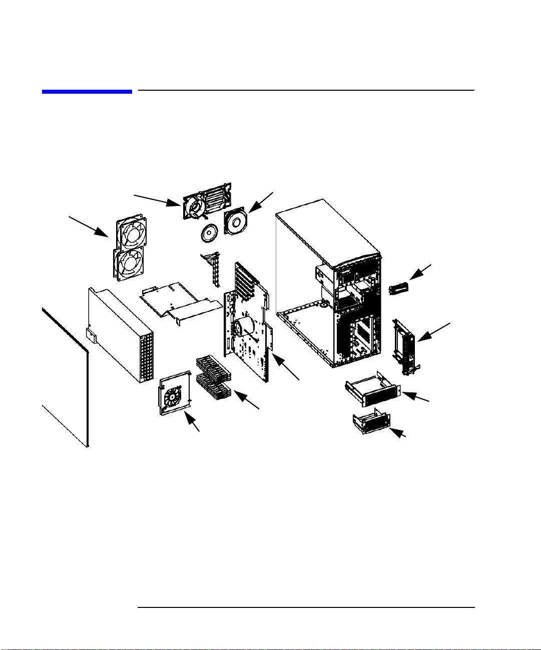
Product Exploded Diagram
Refer to the figure below for a basic parts overview of the B1000/C3000
workstation.
Figure 1-1 Exploded View
I/O Fan/Speaker Bracket
tem-Board Fans
ide Panel
Power
Supply
Speaker
I/O Card
Retainer Clip
Air Divider
Memory Fan
I/O Fan
Chassis
Front-Panel Display
Hard Disk Tra
System Board
CD Drive
DIMMs (Memory)
Floppy Drive Tra
14 Chapter1
Page 15

Getting Started
Product Exploded Diagram
Chapter 1 15
Page 16

Getting Started
Product Exploded Diagram
16 Chapter1
Page 17

2 System Board
Removal/Replacement
This chapter describes how to remove and replace the System Board for
the B1000/C3000 workstation.
17
Page 18

System Board Removal/Replacement
Removing the Terminators and Cables
Removing the Terminators and Cables
1. After powering down the workstation as described in the “Getting
Started” chapter, unplug the power cable from the back of the
workstation. To avoid ESD damage to components, carefully follow
the ESD procedures (also described in the “Getting Started” chapter).
2. Remove the two SCSI terminators from the back of the machine, as
shown below. Or, if you have already replaced either or both of the
terminators with cables to external peripheral devices, remove those
cables., LAN cable, USB cables, and any other cables from the back of
the workstation.
Figure 2-1 Removing all Terminators and Cables
Serial Ports
USB Ports
LAN Port
Parallel Port
Audio In/Out Ports
SCSI Terminators
Power Plug
18 Chapter2
Page 19

Removing the Side Panel
1. Removethe two T-15 Torxthumbscrews locatedin the top and bottom
right edge of the back side of the workstation, as shown below.
Figure 2-2 Opened Side Panel
System Board Removal/Replacement
Removing the Side Panel
Side-Panel Thumbscrew
2. Removethe left side panel by grasping the backedge of the panel and
Hinge Slots
2
rotating the panel outward as shown above. Unhinge the panel and
pull it away from the workstation. Set the panel and its screws aside.
Side-Panel Hook
NOTE Only the left side panel is removed. The left side panel is the one on the
left when facing the front of the workstation.
Chapter 2 19
Page 20

System Board Removal/Replacement
Removing the Power Supply
Removing the Power Supply
1. Position the workstation onits side so the powersupply label is facing
you. It is best to use a cushioned surface to protect the exterior of the
system from damage.
2. Position the conductive sheeting so that an inch of one edge is under
the workstation and the rest is flat against the work area to lay
system components on after you remove them. Also ensure that your
static-grounding strap is securely attached to your wrist and to bare
metal on the workstation.
Figure 2-3 Power Supply Screws and Handles
T15 Torx
Thumbscrew
Power Supply
Handle
T15 Torx
Thumbscrew
3. Alternately loosen the two T-15 Torx screws from the corners of the
power supply as shown above.
4. Using the handle, lift up the power supply and place the bail in the
bail lock to hold the power supply upright.
20 Chapter2
Page 21

Figure 2-4 Tipping Up the Power Supply
Spring Hinge
ail
ock
ail
System Board Removal/Replacement
Removing the Power Supply
Right-side Hinge Pin
5. Disconnect the four cables shown below located below the raised
power supply: three system power cables and the SCA hard disk
backplane cable.
Figure 2-5 Location of Power Cables
Power Cables
6. Remove the power supply from the workstation:
a. Holding the power supply handle, remove the bail from the bail
Chapter 2 21
Page 22

System Board Removal/Replacement
Removing the Power Supply
lock (see Figure 2-4 on page 21).
b. Slide the spring hinge lever toward the front of the workstation
and rotate it downward to lock it in place (see Figure 2-4 on page
21).
c. Slide the power supply toward the back of the workstation to
disengage it from the right hinge pin, remove the power supply
and set it aside.
22 Chapter2
Page 23

Removing the Hard Disk Fan
1. Locate the memory DIMMs. The hard disk fan is to the right of these.
2. Disconnect the power cable from the system board that drives the
hard-disk fan.
Figure 2-6 Removing the Hard Disk Fan
an Power Cable
System Board Removal/Replacement
Removing the Hard Disk Fan
Fan Bracket
Fan Bracket Handl
Hard Disk Fan
DIMMs
3. Remove the hard-disk fan by lifting straight up on the handle of the
fan bracket.
Chapter 2 23
Page 24

System Board Removal/Replacement
Removing the Memory Cards (DIMMs)
Removing the Memory Cards (DIMMs)
1. Press downward on the ejector tabs located on each side of the
memory card (DIMM) slot.
Figure 2-7 Removing a DIMM
2. Grasp the memory card by its edges and lift it straight out. Place the
card on the conductive sheeting.
3. Locate the label that shows memory installation sequence for later
reference.
4. Repeat steps 1 and 2 for all memory cards.
24 Chapter2
Page 25

Removing the Air Divider
1. Remove the PCI retainer clip by pulling evenly in the direction of the
“Pull” tabs on the clip and lifting it out of the workstation.
Figure 2-8 Removing the Air Divider
System Board Removal/Replacement
Removing the Air Divider
PCI Retainer Clip
Air Divider
2. Remove the two T-15 Torx screws that secure the air divider to the
chassis.
3. Note the placement of the air divider for later reference.
4. Grasp the air divider and pull it straight up and out toward you. Set
it aside with its screws.
Chapter 2 25
Page 26

System Board Removal/Replacement
Removing the PCI I/O Card(s)
Removing the PCI I/O Card(s)
CAUTION When removing a PCI I/O card, do not rock it from side to side, or the
card may be damaged. After removing each I/O card, locate the label
which indicates the PCI installation sequence, and place it on the
conductive sheeting until needed for re-assembly.
1. Looking down on the PCI cards, remove the bulkhead screw for each
PCI card.
Figure 2-9 Removing the PCI Cards’ Bulkhead Screws
Bulkhead screws
(remove from inside)
Typical PCI Card
2. Grasp the edges of each PCI card and pull it up and out of the
workstation.
26 Chapter2
Page 27

Figure 2-10 Removing the PCI Cards
System Board Removal/Replacement
Removing the PCI I/O Card(s)
3. Repeat Steps 1 and 2 above to remove all the PCI I/O cards.
Chapter 2 27
Page 28

System Board Removal/Replacement
Disconnecting the Cables
Disconnecting the Cables
1. Disconnect the following nine cables from the system board:
• Fan cables for top and bottom system-board fans and I/O fan
• Power cable for CD drive
• Data cables for CD drive and floppy drive
• Front-panel display cable
• Ultra 2 Wide LVD SCSI cable
• Speaker cable
28 Chapter2
Page 29

Figure 2-11 Cable locations
c
c
e
c
p
System Board Removal/Replacement
Disconnecting the Cables
I/O Fan
Power Conne
Speaker Conne
Drive
a Connector
Sys. Board Fan
er Connector
py Drive
a Connector
tom Sys. Board Fan
er Connector
a 2 Wide LVD
I Connector
Front-Panel Dis
Connector
CD Drive Pow
Cable Conne
2. Inspect the system board to ensure that all cables are disconnected.
NOTE The DIMMs are shown for orientation purposes.
Chapter 2 29
Page 30

System Board Removal/Replacement
a
e
Removing and Replacing the System Board
Removing and Replacing the System Board
WARNING To avoid system damage, make sure your static-grounding strap
is securely attached to your wrist and to the bare metal on the
workstation.
Removing the old System Board
1. Ensureall workstation cables are out of the way to avoid interference
or damage when you remove the system board tray.
Figure 2-12 Removing the System Board
System bo
tray handl
Torx Screws
2. Removethe two T-15Torxscrewsthat secure the system board tray to
the rear wall of the workstation.
30 Chapter2
Page 31

System Board Removal/Replacement
Removing and Replacing the System Board
3. Grasp the system-board tray handle and slide the system board tray
toward the front of the workstation to unseat the keyhole standoffs on
the floor of the chassis, underneath the board. Using the handle, lift
the system board tray out of the workstation and place it on the
conductive sheeting.
Installing the new System Board
1. Position the system board tray in the new chassis. When it is flat in
the workstation, align the system board tray’s keyholes with the
standoffs on the side wall of the chassis, and then slide the system
board tray toward the back of the workstation to seat the standoffs
into their corresponding keyholes.
2. Replacethe two T-15Torx screws that secure the system board tray to
the rear wall of the workstation.
3. Place the old system board tray into the protective packaging from
the new replacement system board and put it aside.
Chapter 2 31
Page 32

System Board Removal/Replacement
Reconnecting Cables
Reconnecting Cables
1. Connect the following nine cables to their respective connectors on
the system board (which, for clarity, is again shown outside the
chassis):
• Fan cables for top and bottom system-board fans and I/O fan
• Power cable for CD drive
• Data cables for CD drive and floppy drive
• Front-panel display cable
• Ultra 2 Wide LVD SCSI cable
• Speaker cable
32 Chapter2
Page 33

Figure 2-13 Connecting the Cables
c
c
e
c
p
System Board Removal/Replacement
Reconnecting Cables
I/O Fan
Power Conne
Speaker Conne
Drive
a Connector
Sys. Board Fan
er Connector
py Drive
a Connector
tom Sys. Board Fan
er Connector
a 2 Wide LVD
I Connector
Front-Panel Dis
Connector
CD Drive Pow
Cable Conne
2. Inspect the system board to ensure that all cables are connected (all
cables, except the fan cables, are unique and fit only one connector)
and securely seated—loose connections may result in poor system
performance.
Chapter 2 33
Page 34

System Board Removal/Replacement
Reinserting PCI I/O Cards
Reinserting PCI I/O Cards
NOTE Reference the PCI label in the system for correct installation procedure.
CAUTION When installing a PCI I/O card, do not rock it from side to side, or the
card may be damaged.
CAUTION To ensure optimum system performance and prevent system damage,
install all I/O cards into their original slots. Refer to the I/O slotnumbers
on the back of the workstation.
1. Align the edges of the PCI card with its slot and firmly push down to
connect the card to the system board. Visually inspect and confirm
the connection between the I/O card and the system board.
Figure 2-14 Installing the PCI Cards
2. Looking down on the PCI cards, replace the bulkhead screw for each
PCI card.
34 Chapter2
Page 35

System Board Removal/Replacement
Figure 2-15 Inserting the PCI Cards’ Bulkhead Screws
3. Repeat Steps 1 and 2 above to install all the PCI I/O cards.
Reinserting PCI I/O Cards
Bulkhead screws
(insert from inside)
Typical PCI Card
Chapter 2 35
Page 36

System Board Removal/Replacement
r
r
Reinstalling the Air Divider
Reinstalling the Air Divider
1. Slide the air divider into the workstation.
2. Replace the two T-15 Torx screws—one on the back and one on the
side—that secure the air divider to the chassis.
3. Replacethe PCIretainer clipby inserting its bottom end into the hole
in the air divider, and then pushing upward and inward—making
sure that all the PCI cards’ edges are aligned properly with the
individual retainers on the clip—until the clip clicks into place
against the top panel of the chassis. (The purpose of the air divider is
to keep the airflow that cools the PCI I/O cards separate from the
airflow that cools the system board; without the air divider, the
cooling of the components would be insufficient.)
Figure 2-16 Installing the Air Divider
PCI
Retaine
Clip
T-15
Torx
Thumbs
Air Divide
36 Chapter2
Page 37

Reinserting the Memory Cards (DIMMs)
1. Make sure the ejector tabs are angled outward. Next, align the
notched edge of the memory card with its slot. Insert the memory
card and firmly and evenly push down on each side to lock it into
place. the ejector tabs will angle upward as the memory card is
inserted. Refer to the memory installation label inside the system for
replacing the DIMMs in the correct slots.
Figure 2-17 Reinstalling a DIMM
System Board Removal/Replacement
Reinserting the Memory Cards (DIMMs)
2. Visually inspect and confirm the connection between the memory
card and the system board.
3. Repeat steps 1 and 2 for all memory cards.
Chapter 2 37
Page 38

System Board Removal/Replacement
Reinstalling the Hard Disk Fan
Reinstalling the Hard Disk Fan
1. Locate the area next to the DIMMs from which the fan was removed.
2. Align the hard-disk fan with the fan bracket guide and slide it into
place, making sure the tabs engage the holes in the chassis. The fan
will click into place.
Figure 2-18 Reinstalling the Hard Disk Fan
Hard-Disk Fan
Power Cable
DIMMs
Fan Bracket
Fan Bracket Handl
Hard Disk Fan
3. Reconnect the fan’s power cable to the socket on the system board.
38 Chapter2
Page 39

Reinstalling the Power Supply
1. To install the power supply:
a. Pickup the power supply by the handle and position its right-side
hinge pin into the right side hinge bracket, as shown below.
b. Alignthe shaft ofthe springhinge (onthe leftside) with its hole in
the hinge bracket, release the spring-hinge lever, and let it snap
left into the hole.
c. Reconnect the power supply to the bail lock.
Figure 2-19 Reinstalling the Power Supply
Spring Hinge
System Board Removal/Replacement
Reinstalling the Power Supply
Right-side Hinge Pin
ail
ock
ail
2. Connect the four power cables.
• Three system power cables
• SCA hard-disk backplane power cable
Chapter 2 39
Page 40

System Board Removal/Replacement
Reinstalling the Power Supply
Figure 2-20 Location of Power Cables
Power Cables
3. Liftthe handle edge of the power supply enough to allow the bail lock
to be disengaged from the bail, fold the bail lock down, and the lower
the power supply back into place.
4. Alternatelytighten the two captive T-15 Torx screws in the corners of
the power supply.
40 Chapter2
Page 41

System Board Removal/Replacement
Figure 2-21 Power Supply Screws and Handles
T15 Torx
Thumbscrew
Reinstalling the Power Supply
Power Supply
Handle
T15 Torx
Thumbscrew
5. Carefully tip the workstation back to the upright position.
Chapter 2 41
Page 42

System Board Removal/Replacement
Replacing the Left Side Panel
Replacing the Left Side Panel
1. Replacethe left side panel by holding it an angle and inserting its top
and bottom hinge hooks with their respective slots in the chassis.
Swing the back edge of the panel toward the back of the workstation
and press the panel firmly into place.
Figure 2-22 Opened Side Panel
Side-Panel Thumbscrew
2. Replace the two T-15 Torx thumbscrews that secure the left side
3. For each of the two SCSI connectors on the rear wall of the chassis,
Hinge Slots
1
Side-Panel Hook
2
panel to the chassis.
replace either the external SCSI devices (if you had any such devices
attached previously) or the appropriate terminator (if you didn’t have
any external devices attached). One or the other must be in place.
4. The LVD SCSI bus must be properly terminated.
42 Chapter2
Page 43

3 Wrapping Up
This section contains information to help you confirm that your removal
and replacement procedure was successful. In some cases you will need
to use specific HP-UX commands and utilities to reconfigure the
workstation to recognize the replacement part(s).
43
Page 44

Wrapping Up
Verifying System Operations
Verifying System Operations
To verify the system operation, follow these steps:
1. Reconnect the power cables and any other cables that were
disconnected when opening the workstation.
2. Reconnect all peripheral devices and their associated power cables.
3. Verify that the SCSI terminators are reattached where necessary.
4. Power-on the system (push the power button on the front panel).
5. The console will prompt you to set the LAN ID which was recorded
earlier. It is also next to the serial number label.
6. Reset the BCH path numbers if they are different than the defaults.
7. If the console screen fails to come up, set up a serial terminal on
COM1 and remove the keyboard to force the console to COM1.
8. If the system fails to boot or power up, refer to the Solving Problems
chapter of the B1000/C3000 Owner’s Guide.
If you have any questions,suggestions, or problems with our hardware or
documentation, please contact your designated Hewlett-Packard
representative.
44 Chapter3
 Loading...