


HP TFT7210R
Maintenance and Service Guide
January 2004 (First Edition)
Part Number 349956-001

© Copyright 2004 Hewlett-Packard Development Company, L.P.
The information contained herein is subject to change without notice. The only warranties for HP products
and services are set forth in the express warranty statements accompanying such products and services.
Nothing herein should be construed as constituting an additional warranty. HP shall not be liable for
technical or editorial errors or omissions contained herein.
HP TFT7210R Maintenance and Service Guide
January 2004 (First Edition)
Part Number 349956-001
Audience Assumptions
This guide is for an experienced service technician. HP assumes you are qualified in the servicing
of computer equipment and trained in recognizing hazards in products with hazardous energy
levels and are familiar with weight and stability precautions for rack installations.
Important Safety Information
Before installing this product, read the Important Safety Information document provided.
WARNING: To reduce the risk of personal injury or damage to the
equipment, be sure that:
• The leveling jacks are extended to the floor.
• The full weight of the rack rests on the leveling jacks.
• The stabilizing feet are attached to the rack if it is a single-rack installation.
• The racks are coupled together in multiple-rack installations.
• Only one component is extended at a time. A rack may become unstable if more
than one component is extended for any reason.

3
Contents
Illustrated Parts Catalog 5
Front Panel LEDs and Buttons.............................................................................................................5
Rear Components.................................................................................................................................6
Replaceable Spare Parts 7
HP TFT7210R Spares Kit.................................................................................................................... 7
HP 1U Adjustable Toolless Rails Spares Kit....................................................................................... 7
Removal and Replacement Procedures 9
Safety Considerations ..........................................................................................................................9
Required Tools..................................................................................................................................... 9
Removing the HP TFT7210R ............................................................................................................10
Replacing the HP TFT7210R............................................................................................................. 11
Removing the HP 1U Adjustable Toolless Rails ...............................................................................13
Replacing the HP 1U Adjustable Toolless Rails................................................................................ 14
Removing the Brace Rail Assembly ..................................................................................................15
Replacing the Brace Rail Assembly................................................................................................... 18
Removing the Rear Cover.................................................................................................................. 20
Replacing the Rear Cover ..................................................................................................................21
Operational Overview 25
Powering On and Off the HP TFT7210R...........................................................................................25
Accessing the OSD Main Menu.........................................................................................................25
Exiting the OSD Main Menu .............................................................................................................25
Input Signal Out of Range .................................................................................................................26
Sleep Mode ........................................................................................................................................26
Changing Out the Power Cords..........................................................................................................26
Maintenance 27
Maintenance Guidelines..................................................................................................................... 27
Cleaning the HP TFT7210R...............................................................................................................28
Storing the HP TFT7210R................................................................................................................. 28
Moving a Rack with the HP TFT7210R Installed..............................................................................29
Specifications 31
Environmental Specifications ............................................................................................................31

4 HP TFT7210R Maintenance and Service Guide
Physical Specifications ......................................................................................................................31
Acronyms and Abbreviations 33
Index 35

5
Illustrated Parts Catalog
In This Section
Front Panel LEDs and Buttons .......................................................................................................5
Rear Components ...........................................................................................................................6
Front Panel LEDs and Buttons
Item Description Function
1 Power On/Off button Powers the monitor on and off.
2 Power Indicator LED Indicates the power states of the HP
TFT7210R.
• Green—full power
• Amber—Sleep mode (on page 26
and Input Signal Out of Range
3 Plus (+) button Scrolls up in the OSD menus and
adjusts the functions.
4 Minus (-) button Scrolls down in the OSD menus and
adjusts the functions.
)
6 HP TFT7210R Maintenance and Service Guide
Item Description Function
5 Menu Select button Launches the first and second level
OSD menus and exits the menus and
OSD.
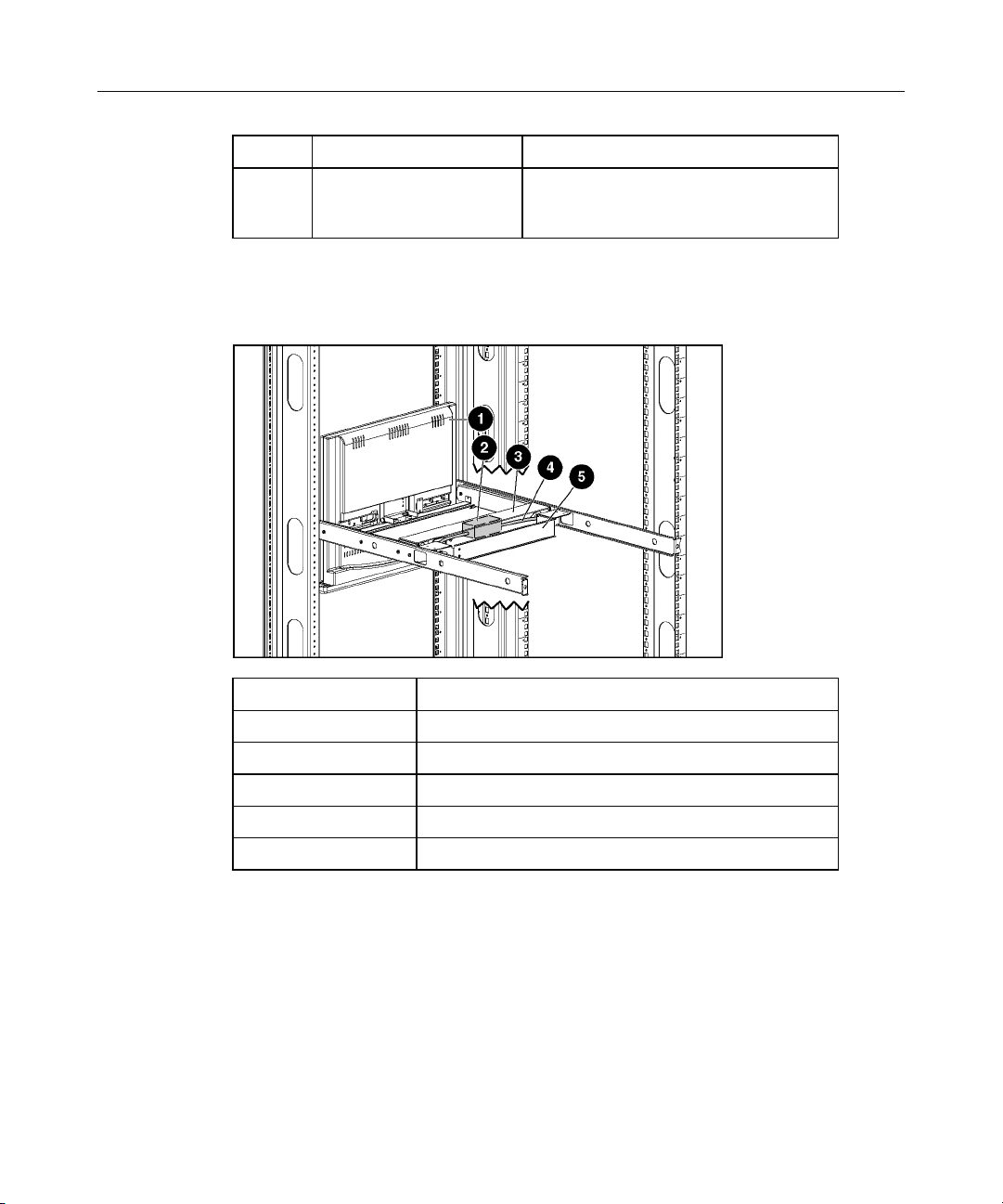
Rear Components
Item Description
1 HP TFT7210R
2 AC adapter
3 Rear cover
4 Power cord
5 Brace rail assembly
7
Replaceable Spare Parts
In This Section
HP TFT7210R Spares Kit...............................................................................................................7
HP 1U Adjustable Toolless Rails Spares Kit .................................................................................7
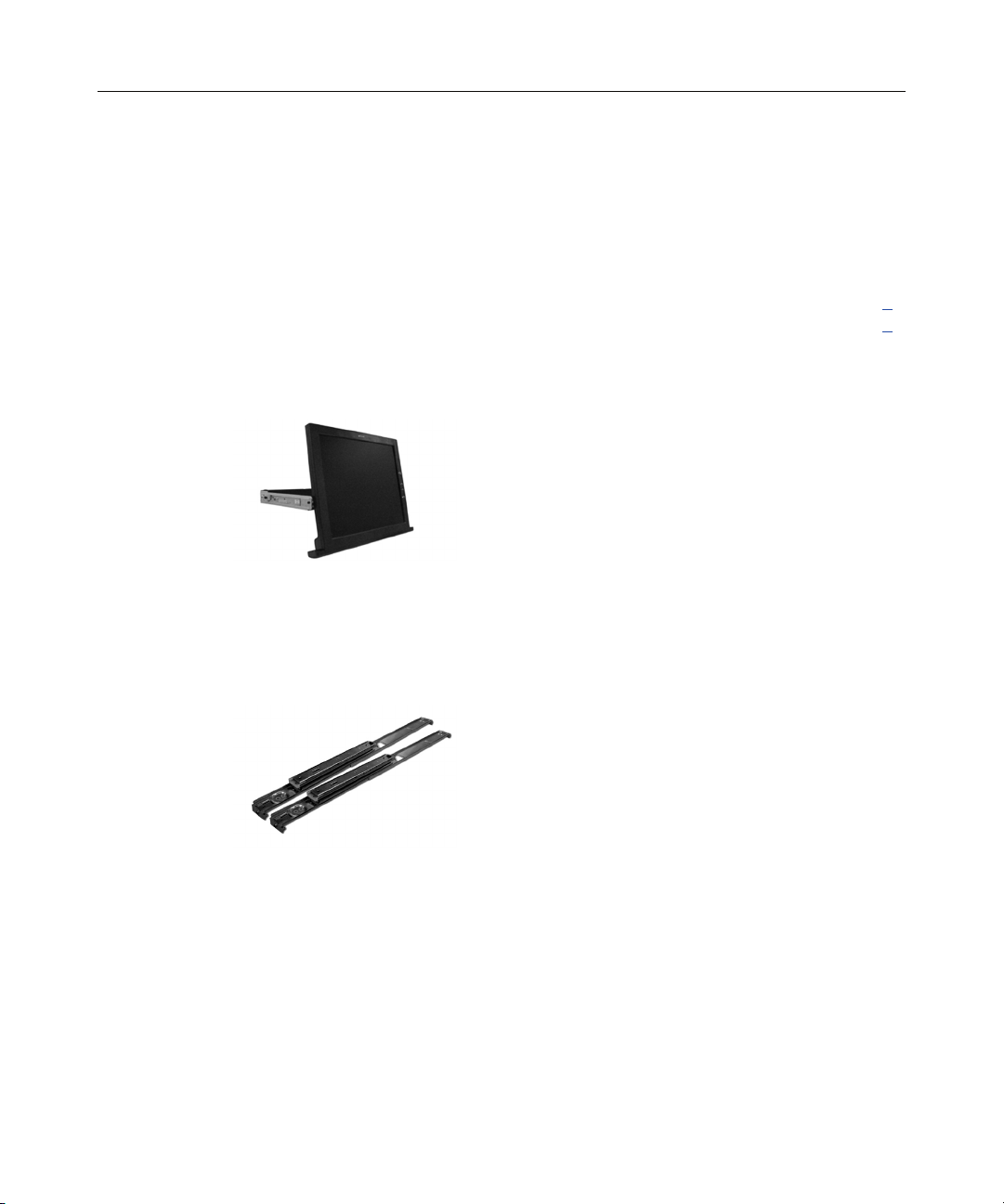
HP TFT7210R Spares Kit
353885-001 SPS—MONITOR, 1U
HP 1U Adjustable Toolless Rails Spares Kit
353886-001 SPS—RAIL KIT, ADJ TOOL-LESS, SHORT SLIDE


9
Removal and Replacement Procedures
In This Section
Safety Considerations.....................................................................................................................9
Required Tools ...............................................................................................................................9
Removing the HP TFT7210R.......................................................................................................10
Replacing the HP TFT7210R .......................................................................................................11
Removing the HP 1U Adjustable Toolless Rails..........................................................................13
Replacing the HP 1U Adjustable Toolless Rails ..........................................................................14
Removing the Brace Rail Assembly.............................................................................................15
Replacing the Brace Rail Assembly .............................................................................................18
Removing the Rear Cover ............................................................................................................20
Replacing the Rear Cover.............................................................................................................21
Safety Considerations
Important Safety Information
Before servicing this product, read the Important Safety Information
document provided with the HP TFT7210R.
To access some components and perform certain service procedures, you must
power off the HP TFT7210R ("Powering On and Off the HP TFT7210R" on
page 25
).
If the rack environment, cabling configuration, or the HP TFT7210R location in
the rack creates awkward conditions, remove the HP TFT7210R ("Removing the
HP TFT7210R" on page 10
Required Tools
• T-15 Torx screwdriver
• Phillips screwdriver
) from the rack.
10 HP TFT7210R Maintenance and Service Guide
Removing the HP TFT7210R
1. Power off the HP TFT7210R ("Powering On and Off the HP TFT7210R" on
page 25
2. Disconnect and unroute the cables.
).
3. Remove the two screws securing the cable management arm to the rear of the
HP TFT7210R.
4. Pull the release mechanisms toward you with your index fingers to unlock
the inner slides.
Removal and Replacement Procedures 11
5. Continue moving the HP TFT7210R toward you while holding the release
mechanisms and remove the HP TFT7210R from the rack.
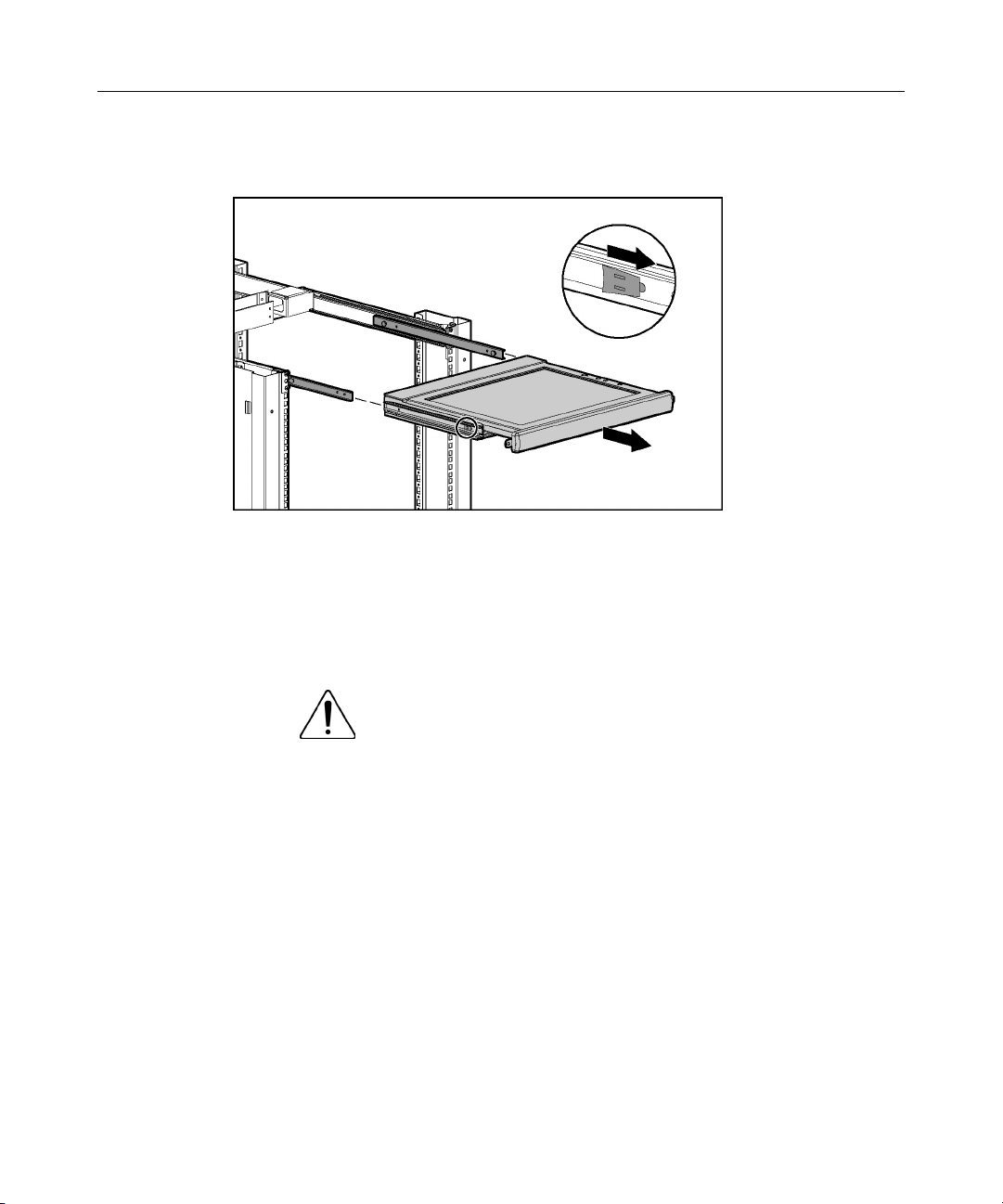
Replacing the HP TFT7210R
1. Extend the inner slides until they lock into place.
2. Align the HP TFT7210R with the extended inner slides, and pull the release
mechanisms toward you while inserting the HP TFT7210R into the rack.
WARNING: To reduce the risk of personal injury, release
the release mechanisms after pushing the HP TFT7210R slightly
forward.

12 HP TFT7210R Maintenance and Service Guide
3. Attach the cable management arm to the rear of the HP TFT7210R with two
screws.

Removal and Replacement Procedures 13
4. Route the cables and plug in the HP TFT7210R.
5. Power on the HP TFT7210R ("Powering On and Off the HP TFT7210R" on
page 25
).
Removing the HP 1U Adjustable Toolless Rails
1. Remove the HP TFT7210R ("Removing the HP TFT7210R" on page 10).
2. Remove the brace rail assembly ("Removing the Brace Rail Assembly" on
page 15
).
3. Locate the spring release.
4. Place your hand on the outside of the HP 1U Adjustable Toolless Rail so that
you can move the spring release.
5. Gently move the spring release toward the inside of the rack (1) while
moving the HP 1U Adjustable Toolless Rail out toward you and away from
the rack (2).

14 HP TFT7210R Maintenance and Service Guide
NOTE: If you cannot gain access to the spring release from the outside
of the HP 1U Adjustable Toolless Rail, a tool might be required to
unlock the spring release from the unit side of the HP 1U Adjustable
Toolless Rail.
6. Repeat the previous steps for the other HP 1U Adjustable Toolless Rail.
Replacing the HP 1U Adjustable Toolless Rails
1. Align the HP 1U Adjustable Toolless Rails with the holes marked with the
rack template, and snap them into place.
a. Snap one end of the HP 1U Adjustable Toolless Rails into the Retma
rails.
b. Extend the other half of the HP 1U Adjustable Toolless Rails to meet the
appropriate rack depth, and snap them into place.
NOTE: If the HP 1U Adjustable Toolless Rails do not snap into place,
be sure that they align with the holes marked with the rack template.
The holes marked with the rack template must be in the same location
for the front and rear of the rack.

Removal and Replacement Procedures 15
2. Replace the brace rail assembly ("Replacing the Brace Rail Assembly" on
page 18
).
Removing the Brace Rail Assembly
1. Disconnect and unroute the cables.

16 HP TFT7210R Maintenance and Service Guide
2. Remove the two screws securing the cable management arm to the rear of the
HP TFT7210R.
3. Remove the three screws securing the brace rail to the HP 1U Adjustable
Toolless Rails.

Removal and Replacement Procedures 17

18 HP TFT7210R Maintenance and Service Guide
4. From the rear of the rack, slide the brace rail assembly out toward you.
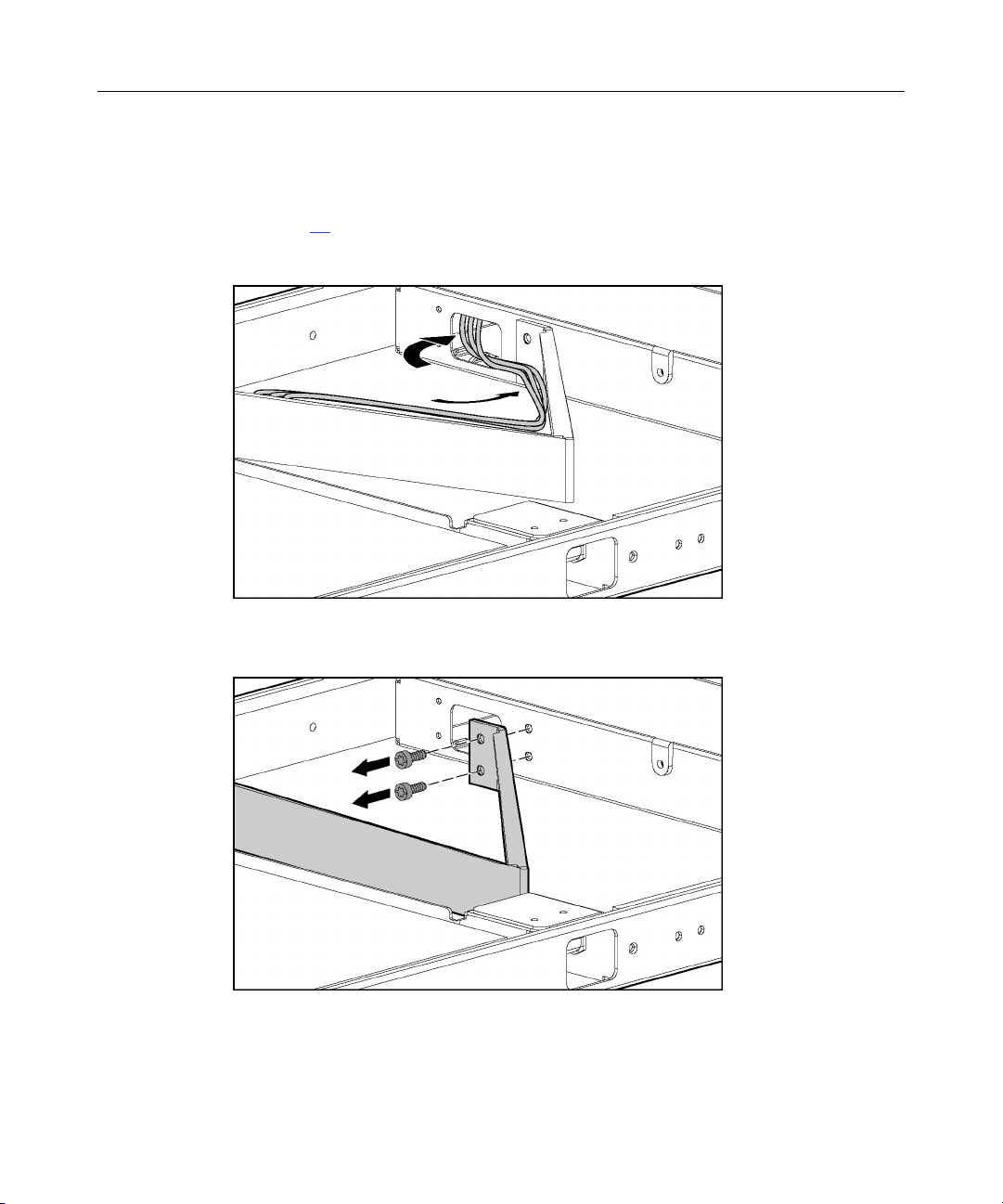
Replacing the Brace Rail Assembly
1. Slide the brace rail assembly into the HP 1U Adjustable Toolless Rails from
the rear of the rack, ensuring that the cable access hole faces the left side of
the rack.
NOTE: The cable access hole must be positioned on the left side of the
rack to enable appropriate routing of the cables.

Removal and Replacement Procedures 19
2. Align the screw holes on the brace rail with the screw holes on the HP 1U
Adjustable Toolless Rails.
3. Secure the brace rail to the HP 1U Adjustable Toolless Rails by inserting
three screws and tightening them.

20 HP TFT7210R Maintenance and Service Guide
4. Attach the cable management arm to the rear of the HP TFT7210R with two
screws.
5. Route the cables and plug in the HP TFT7210R.
Removing the Rear Cover
IMPORTANT: The display must be positioned at a 90 degree angle.

Removal and Replacement Procedures 21
1. Remove the screw.
2. Grasp the rear cover with both hands.
3. Apply pressure to the rear cover using your thumbs (1) while rotating the
rear cover out toward you using your fingers (2).
4. Lift the rear cover away (3).
Replacing the Rear Cover
IMPORTANT: The display must be positioned at a 90 degree angle.

22 HP TFT7210R Maintenance and Service Guide
1. Place the rear cover directly over the metal tray.
2. Be sure the cables are aligned with the openings on the rear of the metal tray
(1) and the front of the rear cover (2).
3. Grasp the rear cover with both hands.
4. Use your thumbs to push the rear cover tabs under the metal tray holders (1)
and snap the rear cover into place (2).

Removal and Replacement Procedures 23
5. Insert the screw.


25
Operational Overview
In This Section
Powering On and Off the HP TFT7210R.....................................................................................25
Accessing the OSD Main Menu ...................................................................................................25
Exiting the OSD Main Menu........................................................................................................25
Input Signal Out of Range............................................................................................................26
Sleep Mode...................................................................................................................................26
Changing Out the Power Cords....................................................................................................26
Powering On and Off the HP TFT7210R
Accessing the OSD Main Menu
Press the Power On/Off button.
1. Press the Menu Select button on the front panel ("Front Panel LEDs and
Buttons" on page 5
). The OSD Main menu appears and the default settings
are shown when first accessing this menu.
2. Scroll down by pressing the Minus (-) button, or scroll up by pressing Plus
(+) button.
3. Press the Menu Select button to activate the highlighted menu item.
If the Menu Select, Minus (-), or Plus (+) buttons remain untouched for the time
duration that has been set by the OSD Timeout function, any new settings that
have not been saved will be discarded and the previously saved settings are
restored.
Exiting the OSD Main Menu
From the OSD Main menu, highlight Exit, and then press the Menu Select
button to exit and close the OSD Main menu.

26 HP TFT7210R Maintenance and Service Guide
Input Signal Out of Range
An input signal that is outside the normal range of operation defined by the
capabilities of the HP TFT7210R, causes a "Selected resolution is not within
recommended range of operation" message to appear for 30 seconds.
Sleep Mode
After losing video signal, for supported video resolutions, a "Check Cable"
message appears and is stationary for two seconds. The display then goes blank,
the monitor powers off, and the LED is amber.
For unsupported video modes that exceed 1280 X 1024 at 76 Hz, the display has
a black background, the LED is amber, and a "Selected resolution is not within
recommended range of operation" message appears for 20 seconds. After losing
video signal, the message disappears.
Changing Out the Power Cords
Before installing the HP TFT7210R into the rack, determine which power cord is
appropriate for your rack environment. To replace the high-voltage power cord
with the low-voltage power cord, the rear cover must be removed and replaced
before installation.
To replace the power cord:
1. Remove the rear cover ("Removing the Rear Cover" on page 20
).
2. Remove the screw from the holding clip.
3. Unplug the high-voltage power cord from the AC brick.
4. Plug the low-voltage power cord into the AC brick.
5. Insert the screw into the holding clip and tighten.
6. Replace the rear cover ("Replacing the Rear Cover" on page 21
).

27
Maintenance
In This Section
Maintenance Guidelines ...............................................................................................................27
Cleaning the HP TFT7210R.........................................................................................................28
Storing the HP TFT7210R............................................................................................................28
Moving a Rack with the HP TFT7210R Installed........................................................................29
Maintenance Guidelines
To protect the HP TFT7210R from overheating and other types of damage:
• Use only a power source and connection appropriate for the HP TFT7210R,
as indicated on the agency label.
• If an extension cord or power strip is used, be sure that the cord or strip is
rated for the product. Also, be sure that the total ampere ratings of all
products plugged into the extension cord or power strip do not exceed 80%
of the extension cord or strip ampere ratings label.
• Do not overload an electrical outlet, power strip, or convenience receptacle.
The overall system load must not exceed 80% of the branch circuit rating. If
power strips are used, the load should not exceed 80% of the power strip
input rating.
• Install the HP TFT7210R near an outlet that you can reach easily. Disconnect
the product by grasping the plug firmly and pulling it from the outlet. Never
disconnect it by pulling the cord.
• Unplug the HP TFT7210R from the wall outlet before cleaning. Do not use
liquid cleaners or aerosol cleaners.
• Slots and openings in the monitor are provided for ventilation. These
openings must not be blocked or covered. Never push objects of any kind
into these slots or openings.
• Do not drop the HP TFT7210R or place it on an unstable surface.
• Do not allow anything to rest on the power cord. Do not walk on the cord.

28 HP TFT7210R Maintenance and Service Guide
• Keep the original packing material and box in a storage area in case you need
them later.
• Keep the HP TFT7210R in a well-ventilated area, away from excessive light,
heat, and moisture. Keep the monitor away from high-capacity transformers,
electric motors, and other strong magnetic fields.
• Do not attempt to service this product yourself. Adjust only those controls
that are covered by the operating instructions. If the HP TFT7210R is not
operating properly or has been dropped or damaged, contact your HP
authorized dealer, reseller, or service provider.
Cleaning the HP TFT7210R
1. Power off the HP TFT7210R ("Powering On and Off the HP TFT7210R" on
page 25
2. Wipe the screen with a soft, clean cloth.
If the screen requires additional cleaning, use any anti-static CRT screen cleaner.
).
CAUTION: Do not use benzene, thinner, ammonia, or any volatile
substance to clean the screen or cabinet. These chemicals can damage the screen.
Never use water to clean a screen.
Storing the HP TFT7210R
1. Pull the release mechanism toward you with your index fingers to unlock the
inner slides.
2. In the same motion, release the release mechanism and move the HP
TFT7210R forward into the stored position.
WARNING: To reduce the risk of personal injury, release
the release mechanisms after pushing the HP TFT7210R slightly
forward.

Maintenance 29
Moving a Rack with the HP TFT7210R Installed
When moving the HP TFT7210R installed in a rack, HP recommends installing
the lock plates.
1. Fully extend the HP TFT7210R until the slides lock into place.
2. Place a lock plate behind the corner of the front plastic bezel, being sure that
the top and bottom holes are aligned with the front plastic bezel pins.
3. From behind the corner of the front plastic bezel, insert a 6-32 screw into the
middle hole on the lock plate, securing it to the HP TFT7210R.
4. Repeat steps 2 and 3 to install the other lock plate.
5. Push the HP TFT7210R back into the rack.
6. Insert an M6 screw into the only visible lock plate hole, securing the HP
TFT7210R to the rail.

30 HP TFT7210R Maintenance and Service Guide
7. Repeat step 6 for the other lock plate.

31
Specifications
In This Section
Environmental Specifications.......................................................................................................31
Physical Specifications.................................................................................................................31
Environmental Specifications
Feature Specification
Operating temperature
(independent of altitude)
Nonoperating temperature
(independent of altitude)
Relative humidity 20 to 80%; noncondensing
Operating altitude 0 to 3,658 m (12,000 ft)
Nonoperating altitude 0 to 12,192 m (40,000 ft)
Physical Specifications
Parameter Specification
Monitor height 34.29 cm (13.5 in)
Monitor depth 4.25 cm (1.67 in)
Monitor width 39.6 cm (15.59 in)
Unit weight 6.12 kg (13.5 lb)
5 to 35°C (41 to 95°F)
-20 to 60°C (-4 to 140°F)


33
Acronyms and Abbreviations
CRT
cathode-ray tube
LED
light-emitting diode
OSD
on-screen display
TFT
thin film transistor


35
Index
A
accessing the OSD Main menu 25
B
brace rail assembly 6, 15, 18
buttons 5
C
cable management arm 6, 15, 18
changing out the power cords 26
check cable message 26
cleaning the unit 28
E
environmental specifications 31
exiting the OSD Main menu 25
F
front panel buttons 5
H
HP 1U Adjustable Toolless Rails Spares Kit 7
HP TFT7210R Spares Kit 7
I
illustrated parts catalog 5
L
M
Maintenance 27
moving a rack with the unit installed 29
O
operational overview 25
OSD Timeout 25
P
physical specifications 31
power cord 26
powering on/off 25
R
rear components 6
removal and replacement procedures 9
removing the Brace Rail Assembly 15
removing the HP 1U Adjustable Toolless
Rails 13
removing the rear cover 20
removing the unit 10
replaceable spare parts 7
replacing the Brace Rail Assembly 18
replacing the HP 1U Adjustable Toolless
Rails 14
replacing the rear cover 21
replacing the unit 11
required tools 9
S
safety considerations 9
Sleep Mode 26
specifications 31
storing the unit 28
LED, power button 5
lock plate 29
T
troubleshooting 25, 26

36 HP TFT7210R Maintenance and Service Guide
V
video signal 26
 Loading...