

Page 1

HP Tower Server tc4100
Operations and Maintenance Guide
Online Version: 2.1
December 2002
Page 2

Notice
The information contained in this document is subject to change without notice.
Hewlett-Packard makes no warranty of any kind with regard to this material, including, but not limited
to, the implied warranties of merchantability and fitness for a particular purpose. Hewlett-Packard shall
not be liable for errors contained herein or for incidental or consequential damages in connection with the
furnishing, performance, or use of this material.
Hewlett-Packard assumes no responsibility for the use or reliability of its software on equipment that is not
furnished by Hewlett-Packard.
This document contains proprietary information that is protected by copyright.
All rights are reserved. No part of this document may be photocopied,
reproduced, or translated to another language without the prior written consent
of Hewlett-Packard Company.
Windows NT
countries. Novell
trademark of the International Business Machines Corporation. SCO
trademarks of The Santa Cruz Operation. UNIX
countries, licensed exclusively through X/Open Company Limited. pcANYWHERE32™is a trademark of
Symantec Corporation. Red Hat
®
, Windows 95®, and Windows 98® are registered trademarks of Microsoft in the U.S. and other
®
and NetWare® are registered trademarks of Novell, Incorporated. OS/2® is a registered
®
is a registered trademark in the United States and other
®
is a registered trademark of Red Hat Incorporated. Linux® is a registered
®
and SCO® UNIX® are registered
trademark of Linus Torvald.
Pentium™ is a U.S. trademark of Intel Corporation.
3M is a trademark of the Minnesota Mining and Manufacturing Company. Torx
CamCar/Textron, Inc. Tinnerman
®
is a registered trademark of Eaton/Tinnerman.
®
is a registered trademark of
English
Hewlett-Packard Company
Network Server Division
Technical Communications/MS 45SLE
10955 Tantau Avenue
Cupertino, CA 95014 USA
© Copyright 2002, Hewlett-Packard Company.
Audience Assumptions
This guide is for the person who installs, administers, and troubleshoots LAN servers. Hewlett-Packard
Company assumes you are qualified in the servicing of computer equipment and trained in recognizing hazards
in products with hazardous energy levels.
ii
Page 3

Contents
1 Control and Indicators . . . . . . . . . . . . . . . . . . . . . . . . . . . . . . . . . . . . . . . . 5
Front Panel Control and Indicators . . . . . . . . . . . . . . . . . . . . . . . . . . . . . . . . . . . 5
Power, Reset, and Keyboard Lock Buttons . . . . . . . . . . . . . . . . . . . . . . . . . . . . . 8
Front Panel LED Indicators . . . . . . . . . . . . . . . . . . . . . . . . . . . . . . . . . . . . . 9
Internal Diagnostic Panel (Optional Accessory) . . . . . . . . . . . . . . . . . . . . . . . . . . 10
Hot Swap Disk Drive Indicators . . . . . . . . . . . . . . . . . . . . . . . . . . . . . . . . . . 12
Non-Hot Swap Disk Drive Indicators. . . . . . . . . . . . . . . . . . . . . . . . . . . . . . . . 12
Rear Panel Indicators and Ports . . . . . . . . . . . . . . . . . . . . . . . . . . . . . . . . . . 12
Power Supply Indicator . . . . . . . . . . . . . . . . . . . . . . . . . . . . . . . . . . . . . . 13
Communication Ports . . . . . . . . . . . . . . . . . . . . . . . . . . . . . . . . . . . . . . . 13
NIC Indicators . . . . . . . . . . . . . . . . . . . . . . . . . . . . . . . . . . . . . . . . . . . 14
Applying Power to the HP Server tc4100 . . . . . . . . . . . . . . . . . . . . . . . . . . . . . . . 14
Powering Up the HP Server tc4100 . . . . . . . . . . . . . . . . . . . . . . . . . . . . . . . . 14
Powering Down the HP Server tc4100. . . . . . . . . . . . . . . . . . . . . . . . . . . . . . . 14
Connecting AC Power to Multiple-Server Configurations . . . . . . . . . . . . . . . . . . . . . 15
Sleep States (ACPI) . . . . . . . . . . . . . . . . . . . . . . . . . . . . . . . . . . . . . . . . 15
2 External Connectors . . . . . . . . . . . . . . . . . . . . . . . . . . . . . . . . . . . . . . . . 16
Mini-DIN (PS/2) for Mouse and Keyboard . . . . . . . . . . . . . . . . . . . . . . . . . . . . . . 16
Serial Port . . . . . . . . . . . . . . . . . . . . . . . . . . . . . . . . . . . . . . . . . . . . . . 16
Parallel Port . . . . . . . . . . . . . . . . . . . . . . . . . . . . . . . . . . . . . . . . . . . . . 17
USB . . . . . . . . . . . . . . . . . . . . . . . . . . . . . . . . . . . . . . . . . . . . . . . . . . 18
Standard Video . . . . . . . . . . . . . . . . . . . . . . . . . . . . . . . . . . . . . . . . . . . . 18
Standard SCSI . . . . . . . . . . . . . . . . . . . . . . . . . . . . . . . . . . . . . . . . . . . . 19
Standard LAN. . . . . . . . . . . . . . . . . . . . . . . . . . . . . . . . . . . . . . . . . . . . . 20
3 Installing and Configuring . . . . . . . . . . . . . . . . . . . . . . . . . . . . . . . . . . . . . 21
Opening and Closing the HP Server tc4100 . . . . . . . . . . . . . . . . . . . . . . . . . . . . . 21
Introduction . . . . . . . . . . . . . . . . . . . . . . . . . . . . . . . . . . . . . . . . . . . . 21
Removing the HP Server tc4100’s Covers. . . . . . . . . . . . . . . . . . . . . . . . . . . . . 21
Removing Covers – Pedestal . . . . . . . . . . . . . . . . . . . . . . . . . . . . . . . . . . . 25
Removing the Pedestal . . . . . . . . . . . . . . . . . . . . . . . . . . . . . . . . . . . . . . 27
Mass Storage Devices . . . . . . . . . . . . . . . . . . . . . . . . . . . . . . . . . . . . . . . . 29
Introduction . . . . . . . . . . . . . . . . . . . . . . . . . . . . . . . . . . . . . . . . . . . . 29
Installing Storage Devices After Shipment. . . . . . . . . . . . . . . . . . . . . . . . . . . . . 29
Installing Hot Swap Hard Drives . . . . . . . . . . . . . . . . . . . . . . . . . . . . . . . . . . 35
Removing Hot Swap Hard Drives . . . . . . . . . . . . . . . . . . . . . . . . . . . . . . . . . 36
Installing Non-Hot Swap Storage Devices . . . . . . . . . . . . . . . . . . . . . . . . . . . . . 37
Connecting External SCSI Devices . . . . . . . . . . . . . . . . . . . . . . . . . . . . . . . . 39
Memory Modules . . . . . . . . . . . . . . . . . . . . . . . . . . . . . . . . . . . . . . . . . . . 39
Introduction . . . . . . . . . . . . . . . . . . . . . . . . . . . . . . . . . . . . . . . . . . . . 39
DIMM Installation . . . . . . . . . . . . . . . . . . . . . . . . . . . . . . . . . . . . . . . . . 40
DIMM Removal . . . . . . . . . . . . . . . . . . . . . . . . . . . . . . . . . . . . . . . . . . 43
Processors . . . . . . . . . . . . . . . . . . . . . . . . . . . . . . . . . . . . . . . . . . . . . . 44
Introduction . . . . . . . . . . . . . . . . . . . . . . . . . . . . . . . . . . . . . . . . . . . . 44
1
Page 4

Tools Required. . . . . . . . . . . . . . . . . . . . . . . . . . . . . . . . . . . . . . . . . . . 44
Processor Configuration Guidelines . . . . . . . . . . . . . . . . . . . . . . . . . . . . . . . . 44
Accessory Boards . . . . . . . . . . . . . . . . . . . . . . . . . . . . . . . . . . . . . . . . . . 49
Introduction . . . . . . . . . . . . . . . . . . . . . . . . . . . . . . . . . . . . . . . . . . . . 49
Tested PCI Boards. . . . . . . . . . . . . . . . . . . . . . . . . . . . . . . . . . . . . . . . . 49
Tools Required. . . . . . . . . . . . . . . . . . . . . . . . . . . . . . . . . . . . . . . . . . . 49
HP Server Remote Management Card . . . . . . . . . . . . . . . . . . . . . . . . . . . . . . 49
Boot Priority . . . . . . . . . . . . . . . . . . . . . . . . . . . . . . . . . . . . . . . . . . . . 49
IRQ Settings . . . . . . . . . . . . . . . . . . . . . . . . . . . . . . . . . . . . . . . . . . . . 50
System Board PCI Slots . . . . . . . . . . . . . . . . . . . . . . . . . . . . . . . . . . . . . . 50
Installing Accessory Boards . . . . . . . . . . . . . . . . . . . . . . . . . . . . . . . . . . . . 51
Configuring the HP Server tc4100 . . . . . . . . . . . . . . . . . . . . . . . . . . . . . . . . . . 54
Introduction . . . . . . . . . . . . . . . . . . . . . . . . . . . . . . . . . . . . . . . . . . . . 54
HP Server tc4100 Navigator CD-ROM. . . . . . . . . . . . . . . . . . . . . . . . . . . . . . . 54
Configuring the Server Using the Navigator CD-ROM. . . . . . . . . . . . . . . . . . . . . . . 56
NOS Installation . . . . . . . . . . . . . . . . . . . . . . . . . . . . . . . . . . . . . . . . . . 59
HP Management Solutions . . . . . . . . . . . . . . . . . . . . . . . . . . . . . . . . . . . . 59
Setup Utility . . . . . . . . . . . . . . . . . . . . . . . . . . . . . . . . . . . . . . . . . . . . 61
SCSI Configuration Utility . . . . . . . . . . . . . . . . . . . . . . . . . . . . . . . . . . . . . 67
Running the Navigator CD-ROM on a Windows PC . . . . . . . . . . . . . . . . . . . . . . . . 67
4 Error Messages . . . . . . . . . . . . . . . . . . . . . . . . . . . . . . . . . . . . . . . . . . . 70
Power-On Self Test (POST) Error Codes . . . . . . . . . . . . . . . . . . . . . . . . . . . . . . 70
Beep Codes . . . . . . . . . . . . . . . . . . . . . . . . . . . . . . . . . . . . . . . . . . . . . 76
5 Diagnostics . . . . . . . . . . . . . . . . . . . . . . . . . . . . . . . . . . . . . . . . . . . . . 78
Power-On Self Test (POST) . . . . . . . . . . . . . . . . . . . . . . . . . . . . . . . . . . . . . 78
No Error Messages Displayed . . . . . . . . . . . . . . . . . . . . . . . . . . . . . . . . . . . 78
HP Server Diagtools . . . . . . . . . . . . . . . . . . . . . . . . . . . . . . . . . . . . . . . . . 80
HP Toptools . . . . . . . . . . . . . . . . . . . . . . . . . . . . . . . . . . . . . . . . . . . . . 82
6 Troubleshooting . . . . . . . . . . . . . . . . . . . . . . . . . . . . . . . . . . . . . . . . . . 83
Preventive Maintenance . . . . . . . . . . . . . . . . . . . . . . . . . . . . . . . . . . . . . . . 83
Troubleshooting Tools . . . . . . . . . . . . . . . . . . . . . . . . . . . . . . . . . . . . . . . 83
Troubleshooting Checklist . . . . . . . . . . . . . . . . . . . . . . . . . . . . . . . . . . . . . 86
BIOS Reset/Update/Recovery . . . . . . . . . . . . . . . . . . . . . . . . . . . . . . . . . . . . 86
BIOS Reset . . . . . . . . . . . . . . . . . . . . . . . . . . . . . . . . . . . . . . . . . . . . 87
BIOS Update/Recovery . . . . . . . . . . . . . . . . . . . . . . . . . . . . . . . . . . . . . . 87
Clearing the BIOS Configuration . . . . . . . . . . . . . . . . . . . . . . . . . . . . . . . . . . . 87
Password Problems . . . . . . . . . . . . . . . . . . . . . . . . . . . . . . . . . . . . . . . . . 88
Supervisor Password . . . . . . . . . . . . . . . . . . . . . . . . . . . . . . . . . . . . . . . 88
User Password. . . . . . . . . . . . . . . . . . . . . . . . . . . . . . . . . . . . . . . . . . . 89
“Operating System Not Found” Message Appears . . . . . . . . . . . . . . . . . . . . . . . . . . 89
Server Stops or Hangs While Starting Up . . . . . . . . . . . . . . . . . . . . . . . . . . . . . . 89
Power Problems . . . . . . . . . . . . . . . . . . . . . . . . . . . . . . . . . . . . . . . . . . . 90
Video or Monitor Problems . . . . . . . . . . . . . . . . . . . . . . . . . . . . . . . . . . . . . . 91
Configuration Problems. . . . . . . . . . . . . . . . . . . . . . . . . . . . . . . . . . . . . . . . 92
The Configuration Cannot Be Saved and the Battery Loses Power or the Configuration Information is
Frequently Lost . . . . . . . . . . . . . . . . . . . . . . . . . . . . . . . . . . . . . . . . . . 92
2
Page 5

Printer Problems . . . . . . . . . . . . . . . . . . . . . . . . . . . . . . . . . . . . . . . . . . . 92
Keyboard Problems. . . . . . . . . . . . . . . . . . . . . . . . . . . . . . . . . . . . . . . . . . 93
Mouse Problems . . . . . . . . . . . . . . . . . . . . . . . . . . . . . . . . . . . . . . . . . . . 93
Floppy Disk Drive Problems . . . . . . . . . . . . . . . . . . . . . . . . . . . . . . . . . . . . . 94
Flexible Disk Drive Problems . . . . . . . . . . . . . . . . . . . . . . . . . . . . . . . . . . . 94
CD-ROM Drive Problems . . . . . . . . . . . . . . . . . . . . . . . . . . . . . . . . . . . . . . . 94
The Server will not boot from a bootable CD . . . . . . . . . . . . . . . . . . . . . . . . . . . 95
SCSI Problems . . . . . . . . . . . . . . . . . . . . . . . . . . . . . . . . . . . . . . . . . . . . 96
A SCSI Device Stops Working . . . . . . . . . . . . . . . . . . . . . . . . . . . . . . . . . . . 97
A SCSI Device Does Not Work After Installation . . . . . . . . . . . . . . . . . . . . . . . . . 97
Processor Problems . . . . . . . . . . . . . . . . . . . . . . . . . . . . . . . . . . . . . . . . . 98
Memory Problems . . . . . . . . . . . . . . . . . . . . . . . . . . . . . . . . . . . . . . . . . . 98
Network Interface Card (Embedded or PCI) Problems . . . . . . . . . . . . . . . . . . . . . . . . 99
If the adapter cannot connect to the network . . . . . . . . . . . . . . . . . . . . . . . . . . . 99
LEDs are not lit on the NIC . . . . . . . . . . . . . . . . . . . . . . . . . . . . . . . . . . . 100
7 Replacing Parts . . . . . . . . . . . . . . . . . . . . . . . . . . . . . . . . . . . . . . . . . . . 101
Safety Information . . . . . . . . . . . . . . . . . . . . . . . . . . . . . . . . . . . . . . . . . 101
Service Tools Required . . . . . . . . . . . . . . . . . . . . . . . . . . . . . . . . . . . . . . . 101
Replacing the Flexible Disk Drive. . . . . . . . . . . . . . . . . . . . . . . . . . . . . . . . . . 101
Removing the Flexible Disk Drive . . . . . . . . . . . . . . . . . . . . . . . . . . . . . . . . 101
Replacing the CD-ROM Drive . . . . . . . . . . . . . . . . . . . . . . . . . . . . . . . . . . . 102
Removing the CD-ROM Drive . . . . . . . . . . . . . . . . . . . . . . . . . . . . . . . . . . 102
Installing the CD-ROM Drive. . . . . . . . . . . . . . . . . . . . . . . . . . . . . . . . . . . 103
Replacing the Hot Swap Drive Cage Backplane . . . . . . . . . . . . . . . . . . . . . . . . . . 104
Removing the Hot Swap Drive Cage Backplane. . . . . . . . . . . . . . . . . . . . . . . . . 104
Installing the Hot Swap Drive Cage Backplane. . . . . . . . . . . . . . . . . . . . . . . . . . 105
Replacing the Fan Assembly . . . . . . . . . . . . . . . . . . . . . . . . . . . . . . . . . . . . 105
Removing the Fan Assembly . . . . . . . . . . . . . . . . . . . . . . . . . . . . . . . . . . 106
Removing the Fan Tray . . . . . . . . . . . . . . . . . . . . . . . . . . . . . . . . . . . . . 106
Replacing the Power Supply . . . . . . . . . . . . . . . . . . . . . . . . . . . . . . . . . . . . 108
Removing the Power Supply. . . . . . . . . . . . . . . . . . . . . . . . . . . . . . . . . . . 108
Installing the Power Supply . . . . . . . . . . . . . . . . . . . . . . . . . . . . . . . . . . . 110
Replacing the System Battery . . . . . . . . . . . . . . . . . . . . . . . . . . . . . . . . . . . 110
Removing the System Battery . . . . . . . . . . . . . . . . . . . . . . . . . . . . . . . . . . 110
Installing the System Battery. . . . . . . . . . . . . . . . . . . . . . . . . . . . . . . . . . . 111
Replacing the System Board Assembly . . . . . . . . . . . . . . . . . . . . . . . . . . . . . . 111
Removing the System Board . . . . . . . . . . . . . . . . . . . . . . . . . . . . . . . . . . 111
Installing the System Board Assembly. . . . . . . . . . . . . . . . . . . . . . . . . . . . . . 113
Installing the Power Distribution Board. . . . . . . . . . . . . . . . . . . . . . . . . . . . . . 115
Replacing the Diagnostic Board . . . . . . . . . . . . . . . . . . . . . . . . . . . . . . . . . . 115
Installing the Diagnostic Board. . . . . . . . . . . . . . . . . . . . . . . . . . . . . . . . . . 116
Removing the Control Panel . . . . . . . . . . . . . . . . . . . . . . . . . . . . . . . . . . . 117
Installing the Control Panel . . . . . . . . . . . . . . . . . . . . . . . . . . . . . . . . . . . 117
8 Parts Information . . . . . . . . . . . . . . . . . . . . . . . . . . . . . . . . . . . . . . . . . . 118
Covers, Fans, Chassis Parts, and Mass Storage. . . . . . . . . . . . . . . . . . . . . . . . . . 118
Power Supplies and Chassis Parts . . . . . . . . . . . . . . . . . . . . . . . . . . . . . . . . . 119
System Board Parts . . . . . . . . . . . . . . . . . . . . . . . . . . . . . . . . . . . . . . . . 119
3
Page 6

9 Specifications . . . . . . . . . . . . . . . . . . . . . . . . . . . . . . . . . . . . . . . . . . . . 122
System Details . . . . . . . . . . . . . . . . . . . . . . . . . . . . . . . . . . . . . . . . . . . 122
Weight and Dimensions . . . . . . . . . . . . . . . . . . . . . . . . . . . . . . . . . . . . . 122
Video Display Modes . . . . . . . . . . . . . . . . . . . . . . . . . . . . . . . . . . . . . . . . 122
Environment . . . . . . . . . . . . . . . . . . . . . . . . . . . . . . . . . . . . . . . . . . . . 124
Power Specification. . . . . . . . . . . . . . . . . . . . . . . . . . . . . . . . . . . . . . . . . 124
Input Power Requirements. . . . . . . . . . . . . . . . . . . . . . . . . . . . . . . . . . . . 124
Power Ratings . . . . . . . . . . . . . . . . . . . . . . . . . . . . . . . . . . . . . . . . . . 125
Power Supply . . . . . . . . . . . . . . . . . . . . . . . . . . . . . . . . . . . . . . . . . . 125
Index . . . . . . . . . . . . . . . . . . . . . . . . . . . . . . . . . . . . . . . . . . . . . . . . . . . . . . . . . . . . . . . . . . . . . . . . . . . . 126
4
Page 7
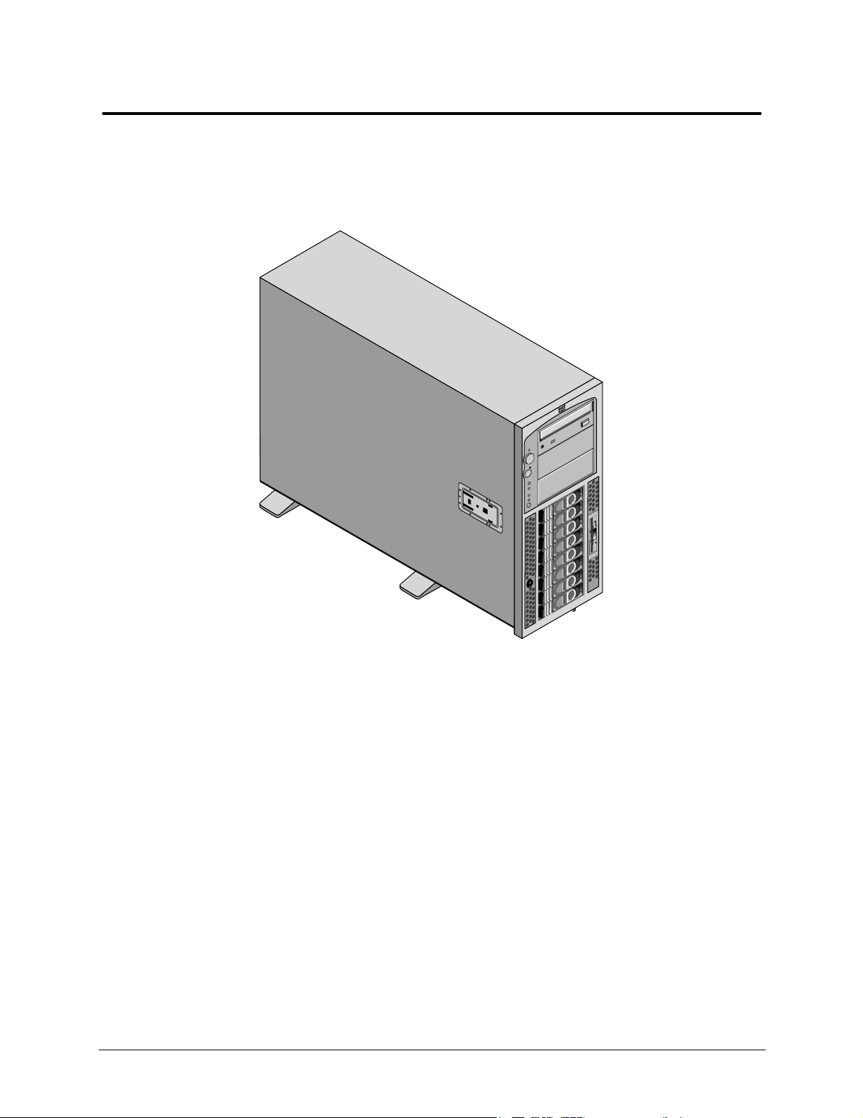
1 Control and Indicators
Front Panel Control and Indicators
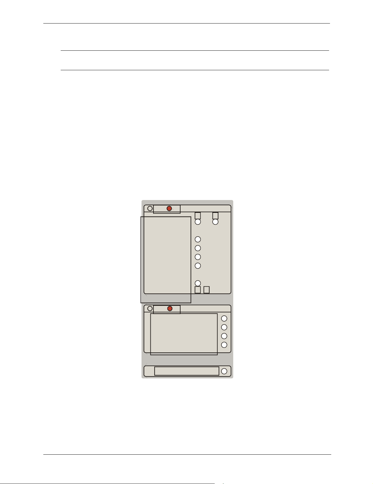
This chapter describes the controls, ports and indicators on the front and rear of the HP Server tc4100. Figure 1-
1, Figure 1-2, Figure 1-3, and Figure 1-4 below show the HP Server tc4100 as pedestal and rack models.
Figure 1-1. HP Server tc4100 Pedestal (front view)
5
Page 8
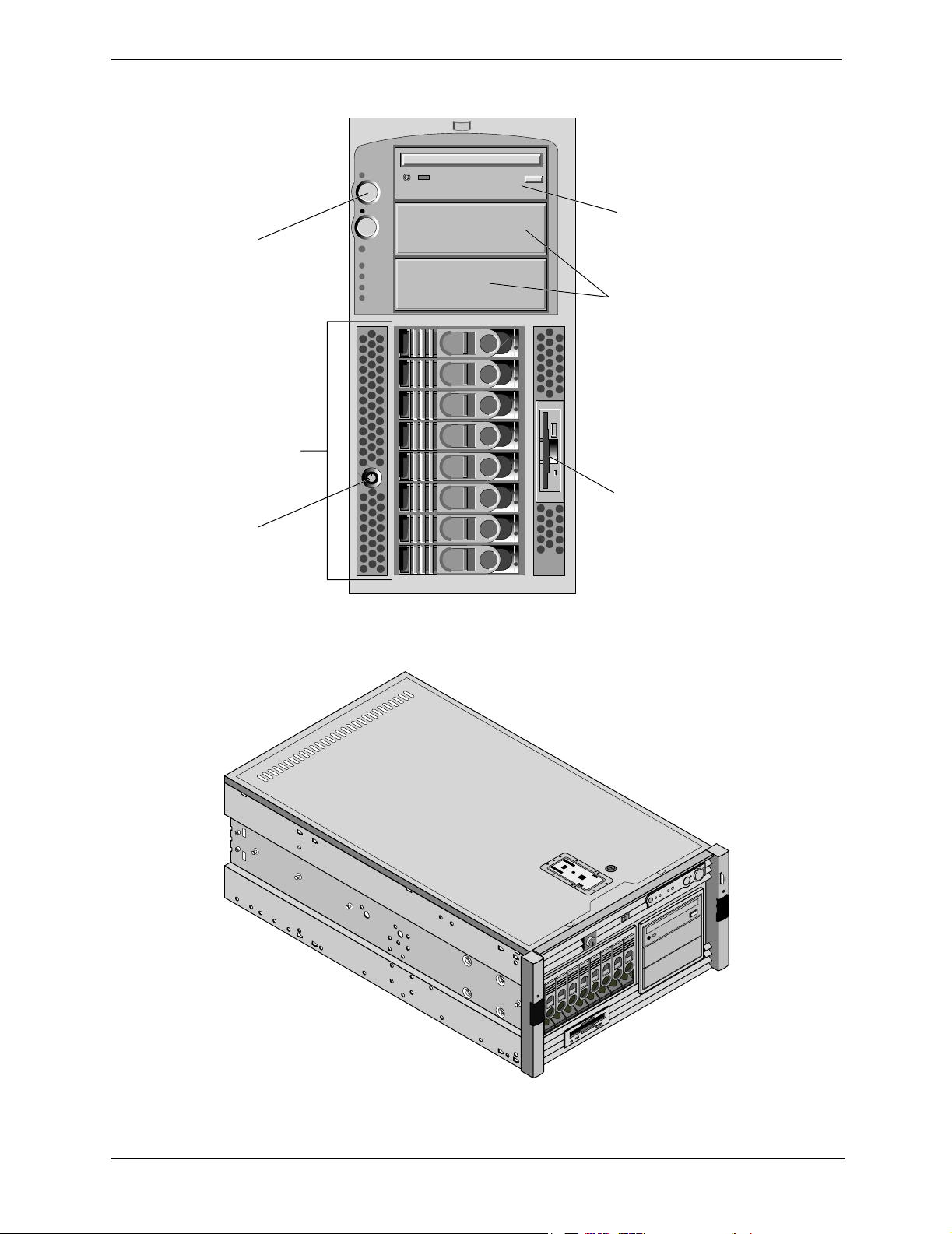
Chapter 1 Control and Indicators
CD-ROM
Drive
Control
Panel
Indicators
Non-hot-swap
Drives (optional)
Hot Swap
Hard Drives
(8 bays)
Flexible Disk
Drive (Floppy)
Hard Drive
Lock
Figure 1-2. HP Server tc4100 Pedestal Bezel
Figure 1-3. HP Server tc4100 Rack (front view)
6
Page 9
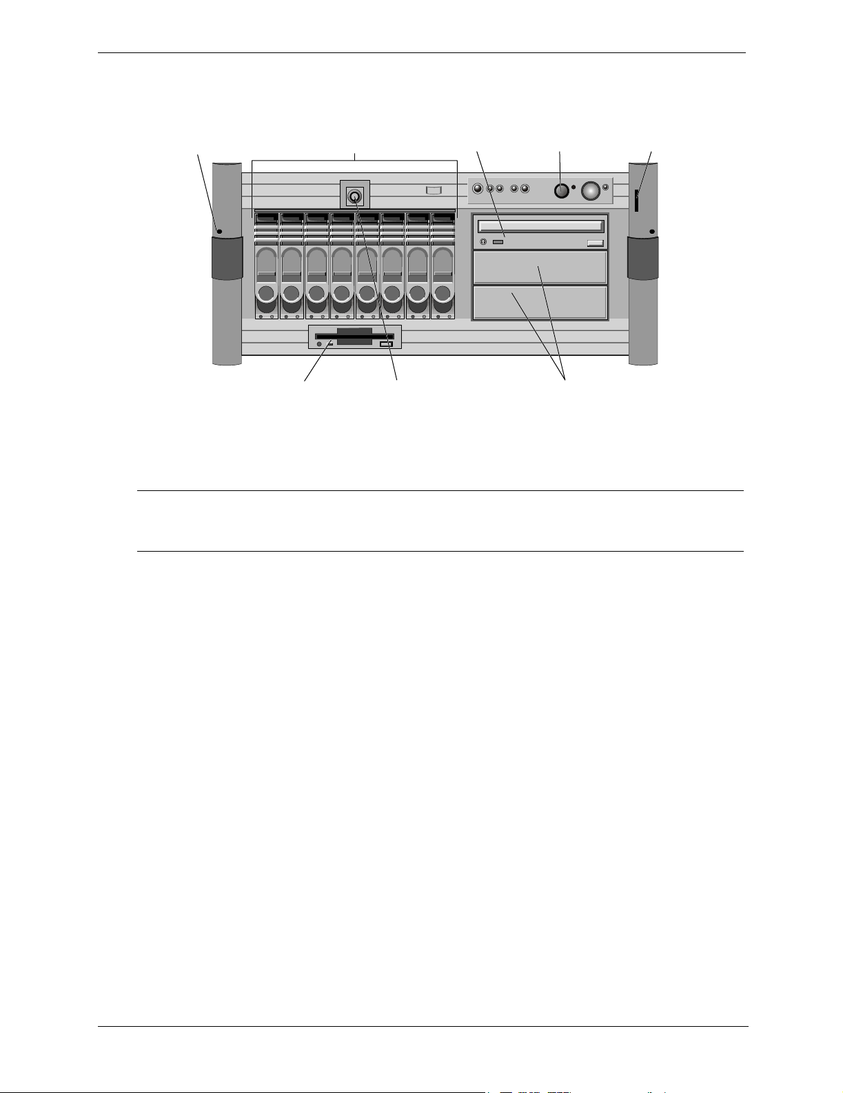
Chapter 1 Control and Indicators
n
C
(
y)
(
)
Rack Tie
Down Screw
(2 places)
Hot Swap
Hard Drives
Flexible Disk
Drive
Flopp
Figure 1-4. HP Server tc4100 Rack Bezel
(8 bays)
Hard Drive
CD-ROM
Drive
Lock
ontrol
Panel
Indicators
Non-hot-swap
Drives
optional
Informatio
Pullout Tab
i
NOTE If the HP Server Remote Management Card accessory is installed, certain LEDs will
function differently. The table below describes the LED functionality with and without
the HP Server Remote Management Card accessory.
7
Page 10
Chapter 1 Control and Indicators
L
h
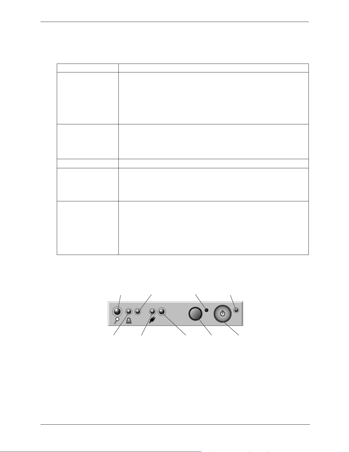
Power, Reset, and Keyboard Lock Buttons
The control buttons shown in Figure 1-5 are described in Table 1-1.
Table 1-1. Power, Reset, and Keyboard Lock Buttons and LEDs
Control/LED Description
Power On/Off/
Sleep Button
Power On/Off/
Sleep LED
Reset Button Performs a system (hard) reset.
Keyboard Lock LED The Keyboard Lock LED has two distinctive states when the server is set to
Locator Button/ LEDs There are two Locator Buttons: one on the front panel (behind the bezel) and the
This button turns the HP Server tc4100 power On or Off, and if available, also
transitions the Server between Power On and sleep states. If sleep states are not
available, then this button only turns power On or Off.
The sleep states are NOS dependent. If your NOS does not support power
management based on the ACPI (Advanced Configuration and Power Interface)
standard, the sleep states are not available. Refer to “Applying Power to the HP
Server tc4100” on page 14.
The Power On/Off/Sleep LED has three distinctive states:
• Blank: No Power
• Green: Power on
• Green Flashing: Sleep mode
“Network Server Mode” through the BIOS setup program:
• Blank: Keyboard lock is not engaged
• Green: Keyboard lock is engaged
other one on the back of the unit (used for a rack configuration). Pressing one of
the buttons toggles the LEDs in synchronous both at the front and the end of the
unit. The Locator LED has two states:
• Dark indicates that the locator feature is not active
• Solid Blue indicates that the locator feature has been activated by the front
switch, rear switch or software utility
ocator
Switch/LED
(service)
Keyboard
Lock LED
LAN A
Status
LED
LAN
A
SYSTEM
Power
Status
LED
Figure 1-5. Drive LED Indicators
Hole Not
Used
RESET
System
Status
LED
Reset
Switch
Button
Power
Switch LED
Power
Switc
Button
8
Page 11

Chapter 1 Control and Indicators
Front Panel LED Indicators
Table 1-2. Component Indicators
Power Supply
Status LED
NOTE: The installation of the HP Server Remote Management Card (optional
accessory) changes this LED behavior.
If the HP Server Remote Management Card is installed, this LED displays:
• Green (Steady): Normal operation. If two power supplies are installed, it indicates
redundancy.
• Red (blinking at 2 Hz blink rate): A subsystem has a critical problem preventing the
server from powering on.
• Amber (blinking 1 Hz blink rate): The power subsystem has lost redundancy since
the last boot, or a fan has failed in a power supply. Please see LED’s on power
supplies for further diagnosis (See Power Supply Indicator)
If the HP Server Remote Management Card is not installed, the LED behavior
observes the following changes:
• It does not indicate Predictive Failure; it only indicates the “good” and “failed”
states.
• It does not blink; it stays lit.
• There can be up to a 1-minute delay between the occurrence of an error condition
and the corresponding LED indication.
• There can be up to a 1-minute delay between the fixing of an error condition and
the corresponding LED indication.
System Status LED NOTE: The installation of the HP Server Remote Management Card (optional
accessory) changes this LED behavior.
If the HP Server Remote Management Card is installed, this LED displays:
• Green (steady): All components are OK
• Yellow (blinking at a rate of 1 Hz ): An internal component may fail soon (i.e.
system fan speed below threshold, predictive memory fail). Check the internal
diagnostic board or the system event log.
• Red (blinking at a rate of 2 Hz): An internal electrical component has failed or there
is a CPU or DIMM configuration error that prevents the system from booting.
Check the internal diagnostic board or the system event log.
If the HP Server Remote Management Card is not installed, the LED behavior
observes the following changes:
• It indicates the current states of the system fans. If the light is green, the fans are ok.
If the light is red, a fan has failed.
• It does not blink; it stays lit.
• There can be up to a 1-minute delay between the occurrence of an error condition
and the corresponding LED indication.
• There can be up to a 1-minute delay between the fixing of an error condition and
the corresponding LED indication.
LAN A LED The LAN A LED has three distinctive states:
• Blank: No LAN link has been established
• Green (steady): A LAN link has been established
• Green (flashing): There is LAN activity
9
Page 12
Chapter 1 Control and Indicators
Internal Diagnostic Panel (Optional Accessory)
NOTE The internal diagnostic panel is included in the optional remote management card
accessory.
The Internal Diagnostic Panel LEDs are located inside the server under the top cover (rack) or left cover
(pedestal). The LEDs have the following behaviors:
• OFF: The component is OK or there is no component.
• ON (color amber): The component needs attention (failure, pre-failure, early-warning condition,
configuration error, etc.). Whenever an LED turns on, the HP Server tc4100 notifies you by turning the
System LED (located in the front panel) to amber or red.
• LEDs are powered as long as AC is present (Vstby). They do NOT turn off when the server is powered off.
• LEDs reflecting actual sensors should turn OFF when the sensors return to normal. Note that a system reset
always returns sensors to normal. If the error condition is still present when the system comes back up, the
sensor should go back to the error state within one minute.
Some LEDs are triggered by SEL events (for example, DIMM configuration error) and will only be cleared by
a system reset. After resetting, the LED should be cleared until a new SEL event is logged. These LEDs should
stay lit even if the server is turned off.
= OK SEE TEC H REFERENC E LABEL
PRO C ESSO R
MEMORY DIMM 0
MEMORY DIMM 1
MEMORY DIMM 2
MEMORY DIMM 3
SYSTEM FAN
= OK SEE TEC H REFERENC E LABEL
PRO C ESSOR C O N FI G
SYSTEM TEMPERATURE
C HEC K EVEN T LO GS
5185-5591 REV. A
1 2
1
SYSTEM BO A RD
MEMORY CONFIG
Figure 1-6. Visual Diagnostic Label
10
Page 13

Chapter 1 Control and Indicators
Table 1-3 describes how to troubleshoot and solve issues using the Internal Diagnostic Panel
Table 1-3. Using the Internal Diagnostic Panel
LED Name Error Conditions Corrective Action
Processor Temperature over
threshold, Internal
CPU Error
1. Check the system event log to view error details. If CPU is over the
temperature threshold, verify that the heat sink and thermal grease
are installed properly--call HP Customer Care. Also check items in
the System Temperature section below.
2. If errors are not resolved, try rebooting the server to resolve the
error.
Memory
DIMM
ECC double and
single bit errors
1. Check the system event log to view error details. If the error is a predictive failure, you may continue to operate the Server, however, the
DIMM should be replaced as soon as possible to avoid unscheduled
downtime. If the error is a double-bit uncorrectable error, the
DIMM should be replaced immediately.
2. If other errors occur, power down the server, unplug the server from
its power source, re-seat the DIMM, and restart the HP Server
tc4100.
System Fan Incorrect fan
speed, predictive
1. Reseat system fan module.
2. If the error is not resolved, replace the system fans.
fan failure, fan
failure
System Board System board
Reboot the HP Server tc4100.
voltage level error
Memory
Configuration
Incorrect memory
type
Check that the installed memory is HP PC133 ECC SDRAM memory.
If this is not correct, replace all DIMMs that are not HP PC133 ECC
SDRAM memory.
Processor
Configuration
System
Temperature
Incompatible
Stepping
Temperature over
threshold
Check the stepping of the processors. Replace any processors that do
not have compatible steppings.
Check the following:
• All system fans are operational
• CPU heat sink is installed correctly on processor with thermal
grease--call HP Customer Care.
• Room temperature within supported temperature range. See Chapter
9 for Environmental Requirements.
• All covers, filler panels and air ducts are installed correctly.
• Adequate ventilation
• Check system event log for further details
If none of the above steps resolves the problem, reboot HP Server
tc4100.
Check Event
Many errors Check the system event log to view error conditions.
Log
The system event log can be accessed from:
• Instant Toptools
• Toptools
• Navigator CD
• Diagtools
11
Page 14
Chapter 1 Control and Indicators
(
)
Hot Swap Disk Drive Indicators
Each of the Hot Swap hard disk drives has two LED indicators, one for operational status and one for activity
status. Light pipes on each drive module transmit light to the front from the LEDs on the inside rear of the hotswap mass storage cage. See Figure 1-5 and Table 1-4.
Table 1-4. Hot Swap Hard Disk Drive LED Indications
Status LED Activity Status LED
Off: Disk not present, or not connected to the
cage
Green (solid): Disk present Green (flashing): Accessing disk
Amber (flashing): Disk failure predicted Green (solid for more than one minute): Disk spinning
Amber (Solid ): Disk failed
Amber (Solid on all drives): Missing SCSI
jumper cable OR SCSI Management Board
Off: No disk activity
up, or “hung”
Non-Hot Swap Disk Drive Indicators
For more information on the HP Tape Drive and its error codes, refer to the documentation provided with the
tape drive or to Hewlett-Packard’s web site, at:
http://www.hp.com
See also the “Mass Storage Devices” on page 29.
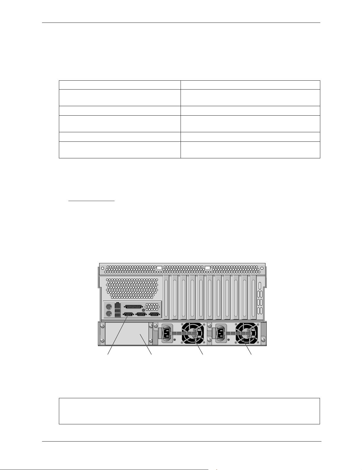
Rear Panel Indicators and Ports
The HP Server tc4100 rear panel includes communication ports, the AC power inlets, and the Server power
supplies.
Figure 1-7 shows the HP Server tc4100s rear panel.
Primary
Power Supply
Ports
Blank CoverRear Panel
Secondary
Power Supply
optional
Figure 1-7. HP Server tc4100 Rear Panel
CAUTION To prevent a power supply from overheating, ensure that the other power supply opening
remains covered, if a second supply is not used. If the second supply is used, keep the
cover in case you need to remove one supply for repair.
12
Page 15
Chapter 1 Control and Indicators
Rel
f
(
)
(
)
L
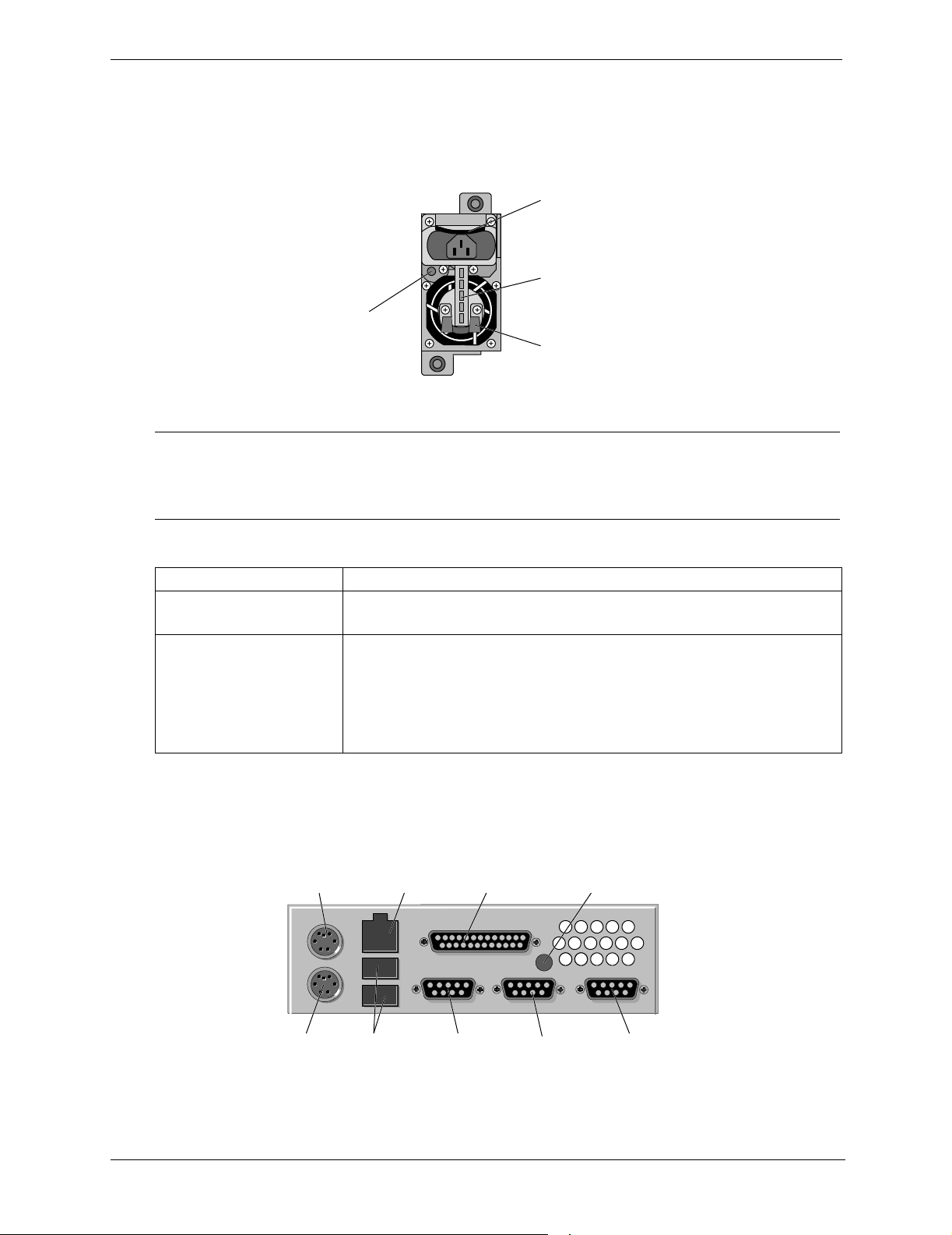
Power Supply Indicator
Each HP Server tc4100 Power Supply has an indicator as shown in Figure 1-8, and each power supply has its
own power cord connection. The HP Server tc4100 comes with one Power Supply (standard); a second Power
Supply for redundancy is optional.
ease
Latch
Handle
Power
Indicator
Figure 1-8. Power Supply LED
NOTE The release latch, which is spring loaded, must be up to insert the power cord. The power
supply cannot be removed from the chassis with the power cord connected to the AC In
connector. The power cord must be removed before pushing down on the release latch to
free the power supply from the chassis.
Strainrelie
Table 1-5. Power Supply LED Indicator Descriptions
Green LED Power Supply and Server Status
Steady Green This indicates that the output voltages are present. It does not indicate the
status of the HP Server tc4100 software.
Off This indicates the Server is powered off, the AC line cord is unplugged, or the
power supply has failed, which may include a fan failure (turning too slowly).
If a fan fails in one of two supplies, the defective supply will continue to
operate until it reaches the thermal shutdown limit. The second power supply
(redundant power supply) will continue to operate providing the necessary
power. Refer to Chapter 6‚ Troubleshooting.
Communication Ports
The connectors on the HP Server tc4100's rear panel are shown in Figure 1-9 and described below.
ocator
Keyboard
(green)
LAN
Port
Parallel Port
(printer)
Switch/LED
(service)
Mouse
purple
USB
Port
Figure 1-9. Rear Panel Ports
Serial
Port A
Serial
Port B
Video SVGA
monitor
13
Page 16

Chapter 1 Control and Indicators
• Keyboard - This port accepts a standard keyboard with a PS/2 connector.
• LAN -This port is an embedded controller that has an RJ-45 LAN connector.
• USB - This port is provided for printers, scanners, and external modems.
• Serial A – This is a standard serial port connector.
• Serial B – This is a standard serial port connector.
• Parallel – This is the standard parallel printer port connection.
• Mouse – This connector accepts a standard PS/2 mouse.
• Video SVGA – This connector provides the video signal to drive the Server's monitor. Refer to “Video
Display Modes” on page 122.
NIC Indicators
The embedded NIC (Network Interface Card) has two LEDs associated with it, which can only be seen from
the rear of the HP Server tc4100. See Table 1-6.
Table 1-6. NIC LED Code
Indicator Definition
Link/Activity LED This LED turns solid green to indicate that it is linked and properly
connected.
The green LED blinks to indicate the embedded NIC (network adapter)
is active and transferring data to/from the NIC. The rate of blinking
varies directly with network traffic.
10/100 Mbps LED This yellow LED turns on to indicate when the NIC is supporting
transfers of 100 Mbps (million bits per second).
When it is off, the NIC is supporting transfers of 10 Mbps.
Applying Power to the HP Server tc4100
Powering Up the HP Server tc4100
1. Ensure that the HP Server tc4100's power cord or power cords are connected to the power source.
See Figure 1-8.
2. Press the Power button on the front control panel. See Figure 1-5.
NOTE Each time AC power is applied (power cord is plugged in), there is a 15 second delay
(self test) before the front control panel will respond to your actions.
Powering Down the HP Server tc4100
1. Log off all users and, if necessary, back-up files. Follow instructions in your network operating system
(NOS) documentation to gracefully shut down all networking software and applications.
2. Press the power switch on the HP Server tc4100 control panel when prompted by the operating system.
3. Normally, this completes the shutdown procedure.
NOTE The power supply will continue to provide standby voltage to the HP Server tc4100 until
the power cord(s) is/are disconnected.
14
Page 17

Chapter 1 Control and Indicators
Connecting AC Power to Multiple-Server Configurations
The HP Server tc4100 temporarily draws a large “inrush current,” when first connected to an AC power source.
When the AC Power is turned off, inrush does not occur. However, in “standby mode” the AC power stays on
and the DC power is turned off.
Initially, the inrush current is much greater than the Server's normal operating current and, generally, the AC
power source can handle this normal inrush current. However, if you install several HP Servers on one circuit,
precautions are necessary. If there is a power failure and power is then restored, all the servers immediately
begin to draw inrush current at the same time. If the circuit breakers on the incoming power line have
insufficient capability, the breaker may trip and thus prevent the servers from powering up.
When preparing your site for installation, allow for the additional inrush current. See “Power Specification”
on page 124.
Sleep States (ACPI)
The HP Server tc4100 supports the ACPI (Advanced Configuration and Power Interface) standard, which is a
key component of a NOS's directed power management. The supported features are only available when an
ACPI-compliant NOS is installed on the Server. The term “sleep state” refers to any of several reduced power
consumption states in which normal NOS activity has ceased.
The Server supports several sleep states, including a sleep state with a short wake-up time, sometimes referred
to as “standby” or “suspend” by various operating systems. In this sleep state the Server appears to be off, and
is indicated by no display on the monitor and no activity for the CD-ROM or internal hard drives. However, the
power LED is slowly flashing and the fans continue to operate.
The HP Server has another sleep state with a slower wake-up time, sometimes referred to as “hibernate” by
various operating systems. In this sleep state, the server appears to be off as described earlier, but the fans and
the front panel power LED are also turned off. The unique feature of this sleep state (and the reason for its
slower wake-up time) is that information about the server's NOS state (open applications, screens, and so on)
is saved to disk before the server is placed in the sleep state. Upon wake-up, this information must be restored
from the disk. This method of restoring the server's operation is much faster than a complete rebooting of the
server. It still requires running all the start-up self-tests before starting the NOS, but loading the NOS and all
the previously opened applications is much faster.
The HP Server supports certain types of system activity, which is used as wake-up events from these sleep
states. These wake-up events can be generated from the power button, LAN activity, and scheduled events.
NOTE The HP Server’s power management policies (transitions between various power states)
and the user options are specific to the particular ACPI-compliant NOS installed on the
server. If your NOS is ACPI-compliant, refer to the power management features in the
instructions provided for more information.
The HP Server’s power button can be configured to initiate a graceful shutdown of the NOS rather than an
immediate shutdown of the power supply. The power button configurations are dependent on the user interface
provided by the ACPI-compliant NOS. While power management is under the control of the ACPI-compliant
NOS, the HP Server’s power button is capable of an override in case of a non-responsive NOS.
NOTE The HP Server power button will force a power-down without waiting for the NOS to
gracefully shut down the server, if the power button is pressed and held more than four
seconds.
CAUTION If the power button override is used, there is a strong possibility that data will be
corrupted or lost.
15
Page 18
2 External Connectors
Unless otherwise noted, the following features apply to all models. Some features are factory installed; others
are optional.
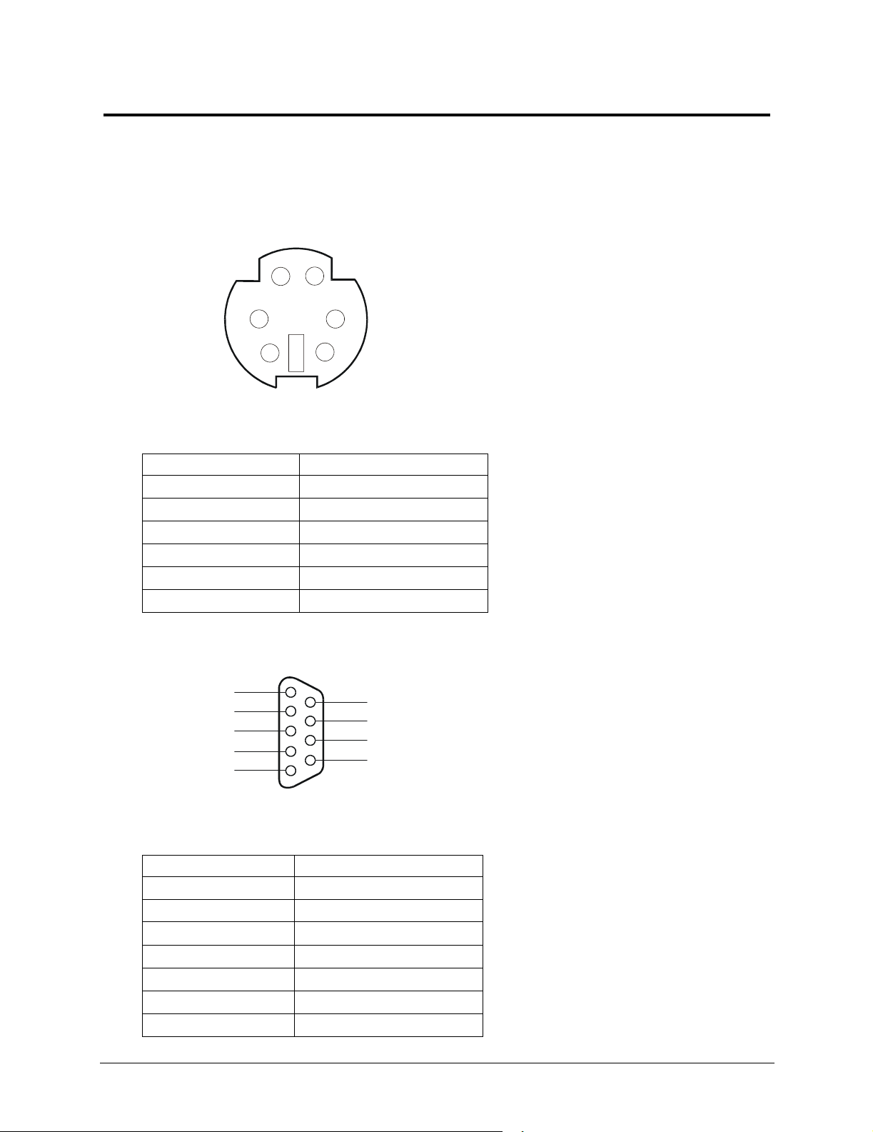
Mini-DIN (PS/2) for Mouse and Keyboard
2
1
3
5
Table 2-1. Mini-DN Signal Description
Pin Number Signal Description
1 Data signal
2Not used
3 Ground
4 Power (+5 V dc)
5 Clock signal
6Not used
Serial Port
5
4
3
2
1
4
6
9
8
7
6
Table 2-2. Serial Port Signal Description
Pin Number Signal Description
1 Data carrier detect
2 Receive data
3 Transmit data
4 Data term ready
5 Signal ground
6 Data set ready
7 Request to send
16
Page 19
Chapter 2 External Connectors
Table 2-2. Serial Port Signal Description
Pin Number Signal Description
8 Clear to send
9 Ring indicator
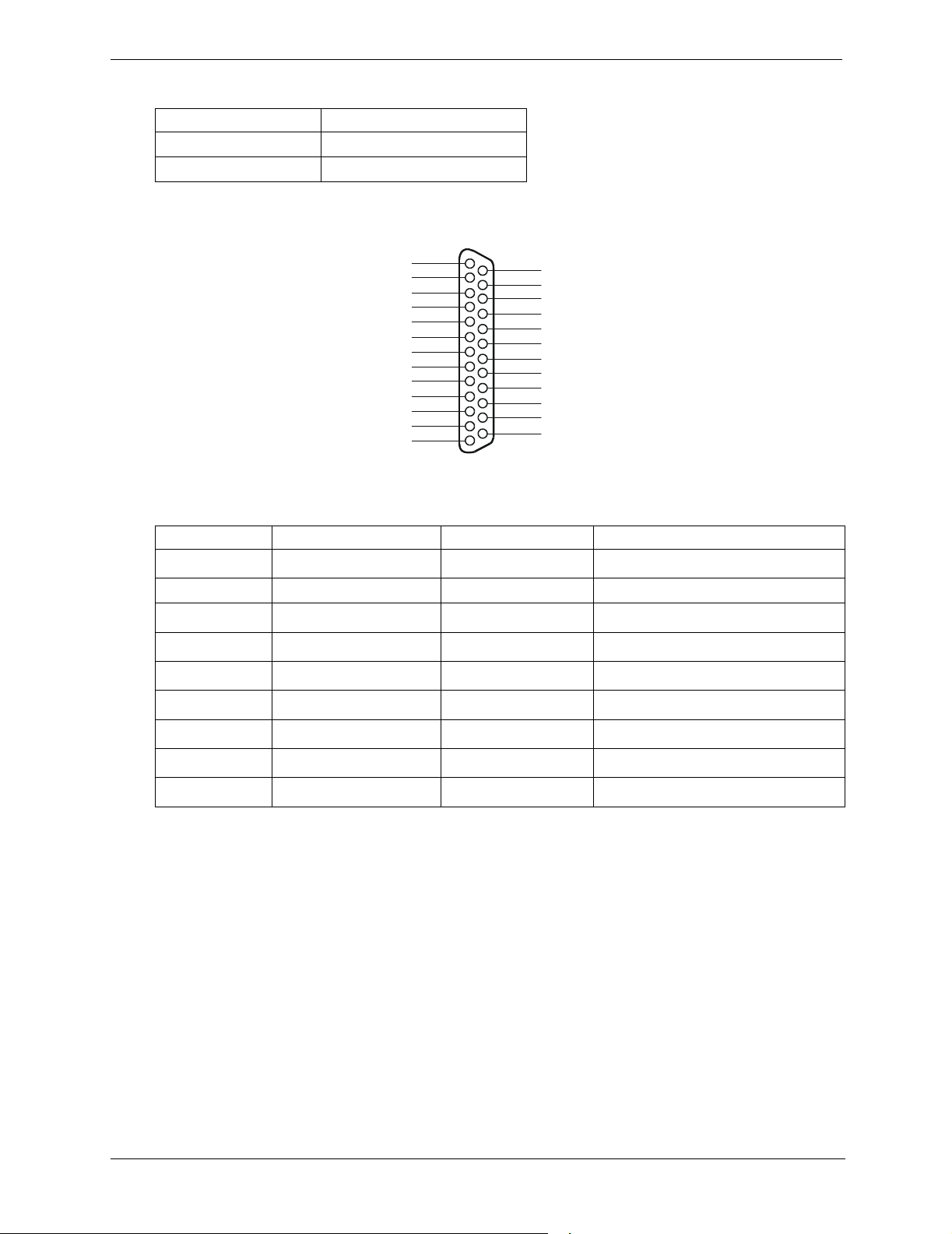
Parallel Port
1
2
3
4
5
6
7
8
9
10
11
12
13
Table 2-3. Parallel Port Signal Description
Pin Number Signal Description Pin Number Signal Description
1 Strobe5 10
14
15
16
17
18
19
20
21
22
23
24
25
Acknowledge
b
2 Data bit 06 11 Busy
3
4
5
6
7
8
9
Data bit 1
Data bit 2
Data bit 3
Data bit 4
Data bit 5
Data bit 6
Data bit 7
a
a
a
a
a
a
a
12 Paper end
13 Select
14
Auto line feed
15 Error1
16
17
Initialize printer
Select in
b
18-25 Signal ground
b
b
a. All data bits are sent to a printer in an 8-bit parallel format.
b. The signal is active low.
17
Page 20
Chapter 2 External Connectors
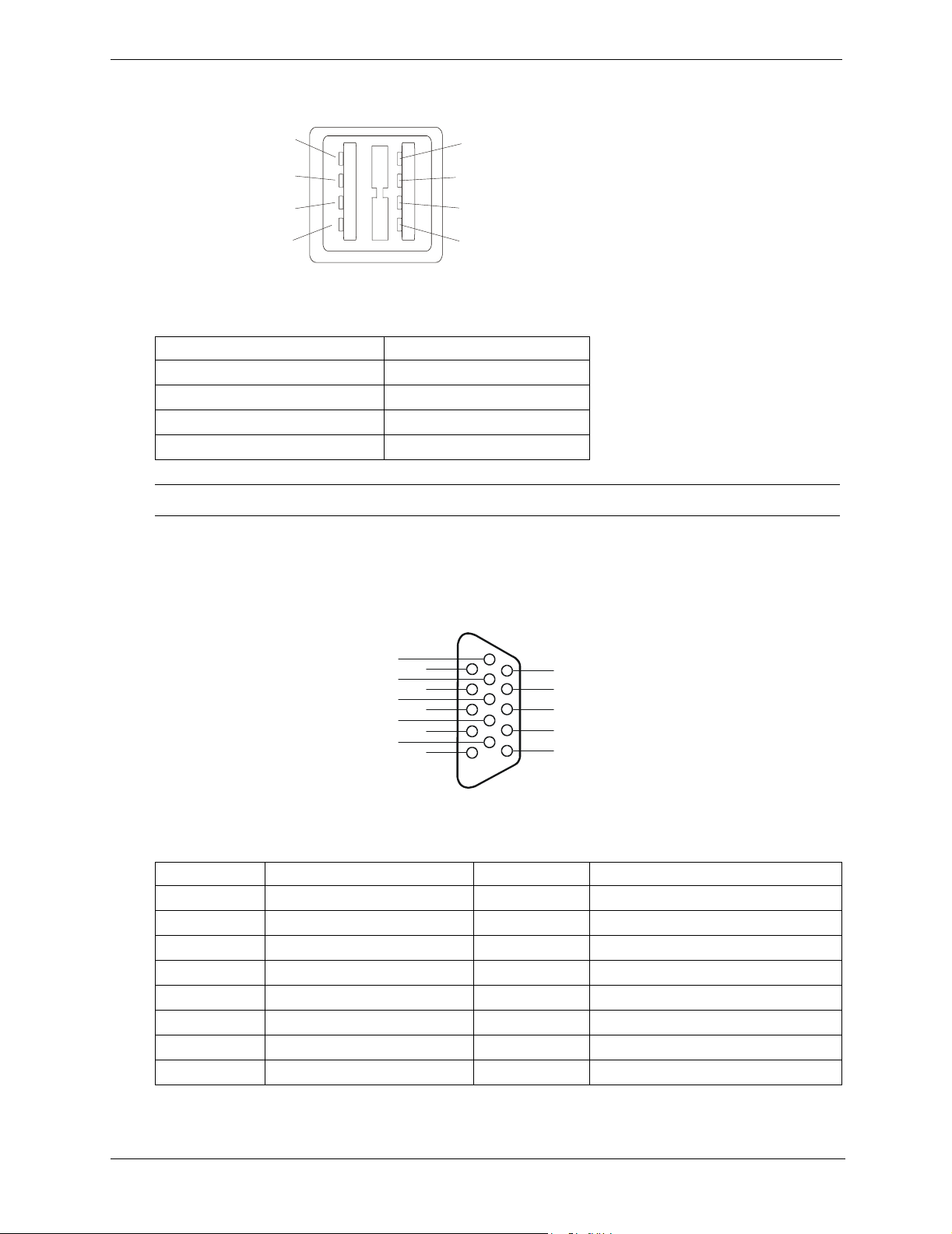
USB
1
2
3
4
Table 2-4. USB Signal Description
Pin Number Signal Description
1
2
3
4
1VBUS
2D+
3D-
4 GND
NOTE Use of the USB port is supported for printers, scanners, and external modems.
Standard Video
The built-in video uses the standard 15-pin analog display pinout configuration. The pinouts for your monitor
may vary. For the pinouts for your monitor, refer to the manual provided with your monitor.
6
1
7
2
8
3
9
4
10
5
Table 2-5. Standard VIdeo Pin Functions
Pin Number Function Pin Number Function
11
12
13
14
15
1 Red 9 Key (no pin)
2 Green 10 Sync return (ground)
3 Blue 11 Monitor ID bit 0
4 Monitor ID bit 2 12 Monitor ID bit 1
5 Monitor self test (ground) 13 Horizontal sync (+)
6 Red return (ground) 14 Vertical sync (-)
7 Green return (ground) 15 Not used
8 Blue return (ground)
18
Page 21

Chapter 2 External Connectors
3
Standard SCSI
35
1
Table 2-6. SCSI Pin Signals
Pin Signal Pin Signal Pin Signal Pin Signal
1 S1 (+DB 12) 18 S18 (TERMPWR) 35 S35 (-DB 12) 52 S52 (TERMPWR)
2 S2 (-DB 13) 19 S19 (RESERVED) 36 S36 (-DB 13) 53 S53 (RESERVED)
3 S3 (+DB 14) 20 S20 37 S37 (-DB 14) 54 S54
4 S4 (+DB 15) 21 S21 (+ATN) 38 S38 (-DB 15) 55 S55 (-ATN)
5 S5 (+DB P1) 22 S22 39 S39 (-DB P1) 56 S56
6 S6 (+DB 0) 23 S23 (+BSY) 40 S40 (-DB 0) 57 S57 (-BSY)
7 S7 (+DB 1) 24 S24 (+ACK) 41 S41 (-DB 1) 58 S58 (-ACK)
8 S8 (+DB 2) 25 S25 (+RST) 42 S42 (-DB 2) 59 S59 (-RST)
9 S9 (DB 3) 26 S26 (+MSG) 43 S43 (-DB 3) 60 S60 (-MSG)
10 S10 (+DB 4) 27 S27 (+SEL) 44 S44 (-DB 4) 61 S61 (-SEL)
11 S11 (+DB 5) 28 S28 (+C/D) 45 S45 (-DB 5) 62 S62 (-C/D)
12 S12 (+DB 6) 29 S29 (+REQ) 46 S46 (-DB 6) 63 S63 (-REQ)
13 S13 (+DB 7) 30 S30 (+I/O) 47 S47 (-DB 7) 64 S64 (-I/O)
14 S14 (+DB P) 31 S31 (+DB 8) 48 S48 (-DB P) 65 S65 (-DB 8)
15 S15 32 S32 (+DB 9) 49 S49 66 S66 (-DB 9)
16 S16 (DIFFSENS) 33 S33 (DB 10) 50 S50 67 S67 (-DB 10)
17 S17 (TERMPWR) 34 S34 (DB 11) 51 S51 (TERMPWR) 68 S68 (-DB 11)
68
4
19
Page 22
Chapter 2 External Connectors
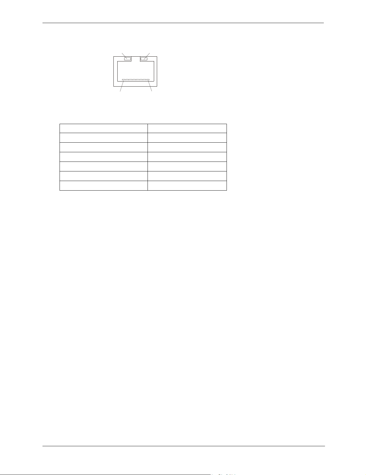
Standard LAN
GRN LED
1
Table 2-7. LAN Signal Description
Pin Number Signal Description
YEL LED
8
1 Data signal
2 Not used
3 Ground
4 Power (+5 V dc)
5 Clock signal
6-8 Not used
20
Page 23

3 Installing and Configuring
Opening and Closing the HP Server tc4100
Introduction
This section describes how to safely extend the rack-mounted HP Server tc4100 out of the rack and how to
remove and replace the covers from the HP Server tc4100 either rack-mounted or in the pedestal. This section
also describes how to remove and replace the pedestal base from the HP Server tc4100.
WARNING Before removing the covers, shut down the operating system and disconnect the power
cords and unplug telephone cables. Disconnect the power cords to avoid exposure to high
energy levels that may cause burns when parts are short-circuited by metal objects, such
as tools or jewelry. Disconnect telephone cables to avoid exposure to a shock hazard from
telephone ringing voltages.
Tools Required
Antistatic service kit (3M™ 8501/8502/8503 or equivalent). This kit includes a static-dissipating work surface,
a chassis clip lead, and a wrist strap.
Removing the HP Server tc4100’s Covers
The HP Server tc4100’s covers are designated top and bottom for the rack-mounted version and left and right
for the pedestal version.
Removing Covers – Rack-Mount
Use this procedure to remove the bezel and then safely extend the Server to where you can remove the covers
(top and bottom) from the HP Server tc4100.
• If you are installing hardware options, you must remove the front bezel, extend the Server, and remove the
top cover. The hardware options include not-hot swap drives, common-tray drives, accessory boards,
DIMMs, and an additional processor, which require access to the interior of the Server.
• If you are only installing or removing hot-swap SCSI disk drives, remove the bezel, but do not extend the
Server or remove the covers.
• If you are only installing the redundant power supply, you do not need to remove the bezel, extend the
Server or remove the covers.
WARNING To prevent injury or system damage, do not operate the HP Server tc4100 with its covers
or front bezel removed, or install items with the power cord connected.
Always disconnect the power cord before removing any covers, to avoid exposure to high
energy levels that may cause burns when parts are short-circuited by metal objects such
as tools or jewelry. Disconnect any telephone cables to avoid exposure to shock hazard
from telephone ringing voltages.
CAUTION To prevent overheating, never operate the Server with its covers removed. This includes
the power supplies and Hot Swap hard disks, which must be replaced or the opening
covered immediately (within 2 minutes).
21
Page 24

Chapter 3 Installing and Configuring
1. If the HP Server tc4100 is operating, log off all users and, if necessary, back up files.
2. Follow instructions in your network operating system (NOS) documentation to gracefully shut down all
networking software and applications.
3. Press the power switch on the HP Server tc4100 control panel when prompted by the operating system.
Normally, this completes the power down procedure.
4. Disconnect the power cord or cords from the power source.
NOTE The power supplies will continue to provide standby current to the Server until the power
cords are unplugged
5. At the front of the HP Server tc4100, extend the anti-tip foot from under the front of the rack.
WARNING This anti-tip device must be extended to prevent the rack and HP Server tc4100 from
tipping over and getting damaged.
6. Unscrew the slide securing screw (2) on each bracket securing the chassis to the column adapter on each
side of the rack.
7. Press in on each blue Slide Release button (2) with both hands to slide the HP Server tc4100 out of the rack.
8. Pull the Server out of the rack until it snaps into the safety locks in each slide with a click.
CAUTION To prevent damage to the covers, support the cover as you remove it from the HP Server
tc4100. The Server’s covers are heavy.
22
Page 25
Chapter 3 Installing and Configuring
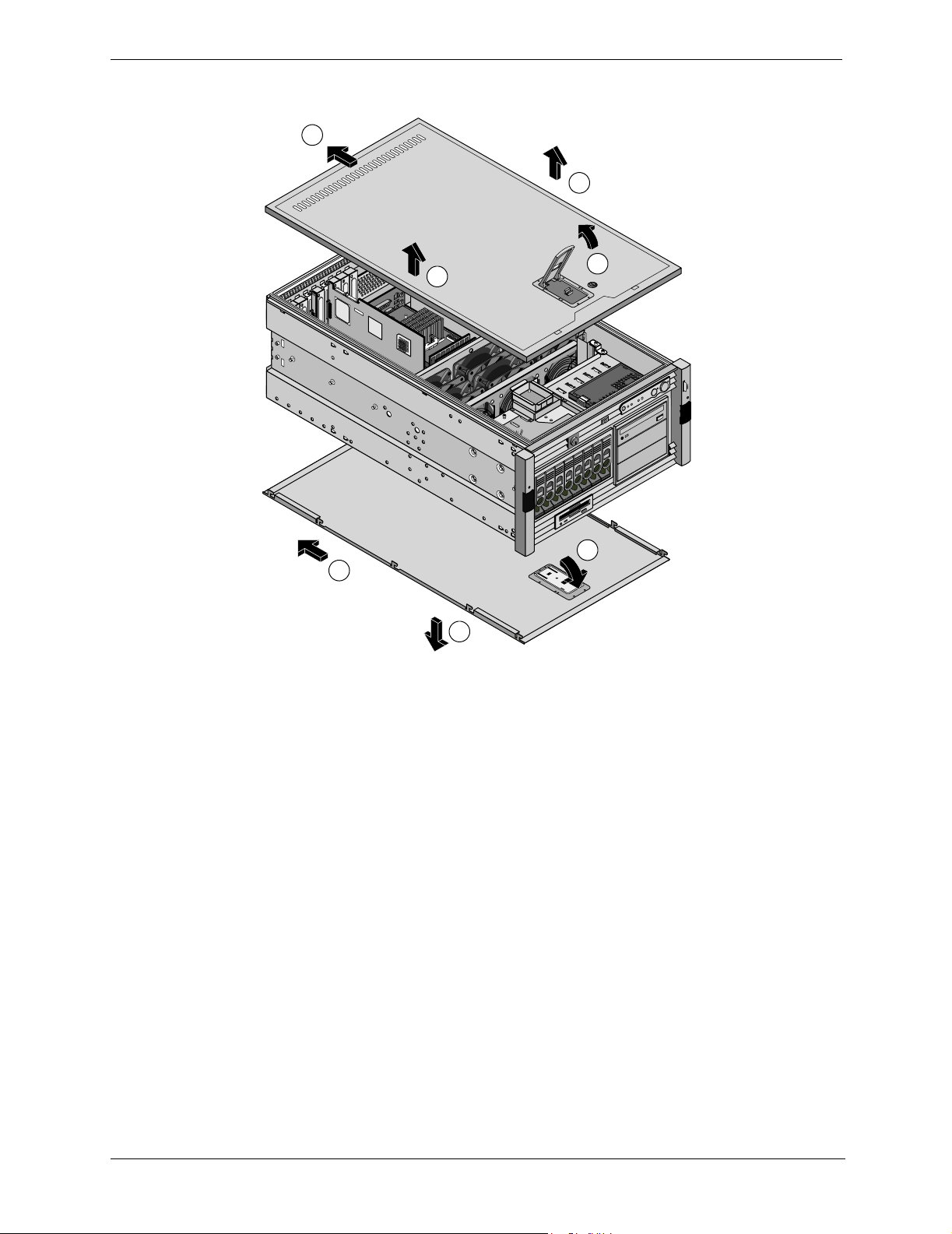
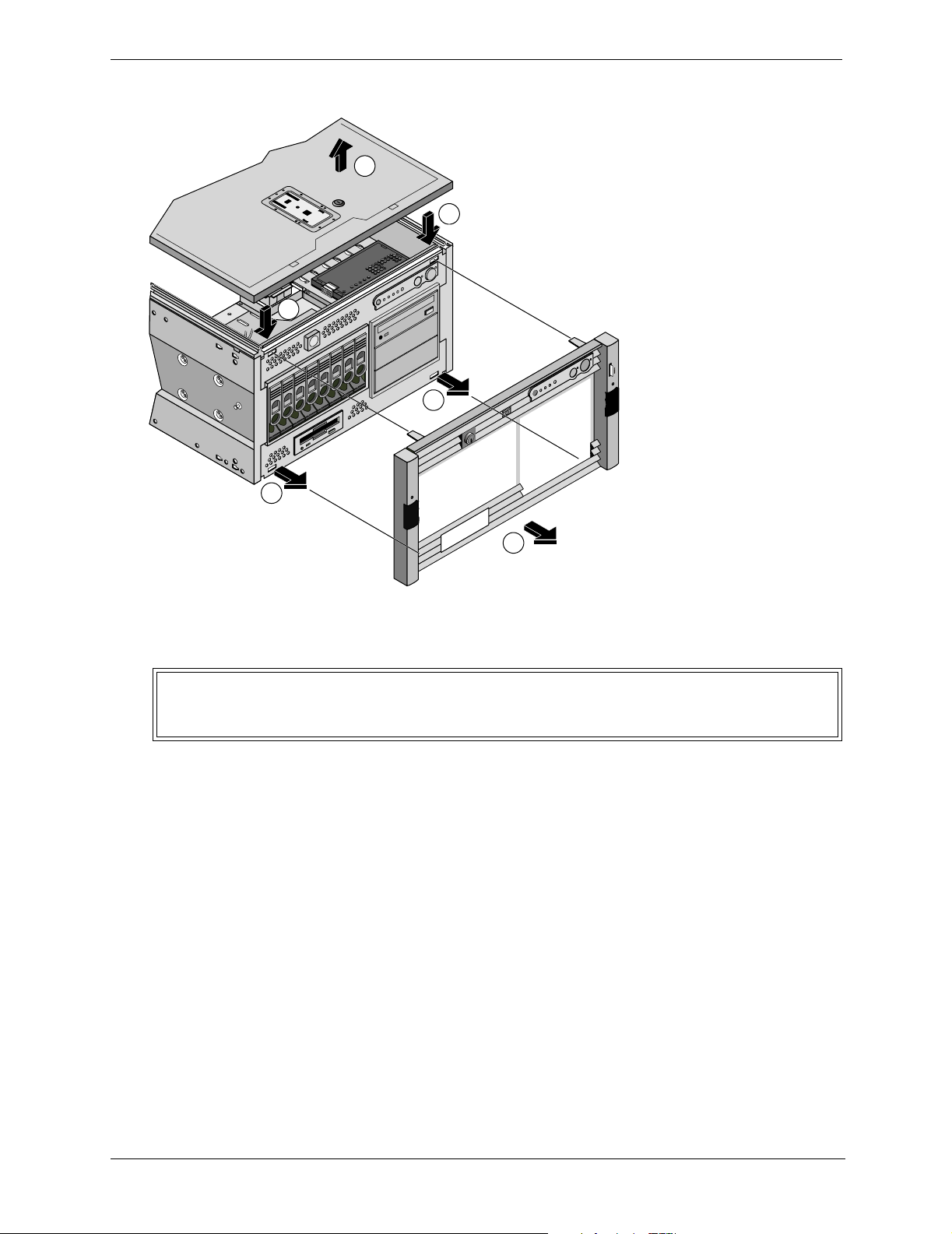
9. To remove the top cover, pull the latch up and lift the top cover away from the server. See Figure 3-1.
2
3
3
2a
3a
1
1a
Figure 3-1. Removing HP Server tc4100 Covers
10. To remove the front bezel, press down on the two self-locking tabs as shown in Figure.
23
Page 26
Chapter 3 Installing and Configuring
e
11. Press down on the two self-locking tabs as shown in Figure 3-3 to release the bezel from the chassis.
1
Note:
2
down on two self-locking tabs to
Remove top cover and press
release the bezel. Bottom tabs will slid
out without removing the bottom cover.
2
3
3
4
Figure 3-2. Removing the HP Server tc4100's Bezel
12. Pull the bezel away from the front of the HP Server tc4100.
WARNING Do not operate the HP Server tc4100 with the bezel removed due to the possibility of
damaging the system with Electrostatic Discharge (ESD) or with foreign objects shorting
out exposed electronic circuits.
13. If necessary, remove the bottom cover by lifting the plastic latch and pulling it forward. See Figure 3-1.
The bottom cover only provides access to the Power Distribution Board and Floppy Disk Drive.
14. Support the bottom cover with your free hand, as you pull the cover forward to disengage it, catching it as
it falls away from the chassis.
15. To replace the top cover, position the cover’s tabs over the respective holes along the top edge on both sides
of the chassis.
16. Slide the cover toward the rear.
17. Close the plastic latch.
18. To replace the bottom cover, position the cover’s tabs under the respective holes along the bottom edge on
both sides of the chassis.
19. Slide the cover toward the rear.
20. Close the plastic latch.
21. Release the safety latches in the slide members on both sides of the chassis.
22. Slide the HP Server tc4100 into the rack.
24
Page 27

Chapter 3 Installing and Configuring
23. To replace the front bezel, line up the 4 tabs into the slots in the chassis. You can then snap the bezel into
place.
24. If the Server is not in a restricted-access area, tighten both slide securing screws.
25. Return the HP Server tc4100 to normal operation.
Removing Covers – Pedestal
Use this procedure to remove the bezel and covers (left & right) on the pedestal version of the HP Server tc4100.
• If you are installing hardware options, you must remove the front bezel and top cover. The hardware options
include accessory boards, DIMMs, and an additional processor.
• If you are only installing or removing SCSI disk drives, remove the bezel, but do not extend the Server or
remove the covers.
WARNING Do not operate the HP Server tc4100 with its covers removed. Always disconnect the
power cord before removing any covers, to avoid exposure to high energy levels that may
cause burns when parts are short-circuited by metal objects such as tools or jewelry.
Disconnect any telephone cables to avoid exposure to shock hazard from telephone
ringing voltages.
CAUTION To prevent overheating, never operate the Server with its covers removed. This includes
the power supplies and Hot Swap hard disks, which must be replaced or the opening
covered immediately (within 2 minutes).
1. If the HP Server tc4100 is operating, log off all users and, if necessary, back up files.
2. Follow instructions in your network operating system (NOS) documentation to gracefully shut down all
networking software and applications.
3. Press the power switch on the HP Server tc4100’s control panel when prompted by the operating system.
Normally, this completes the power-down procedure.
4. Disconnect the power cord(s) from its power source.
25
Page 28
Chapter 3 Installing and Configuring
e
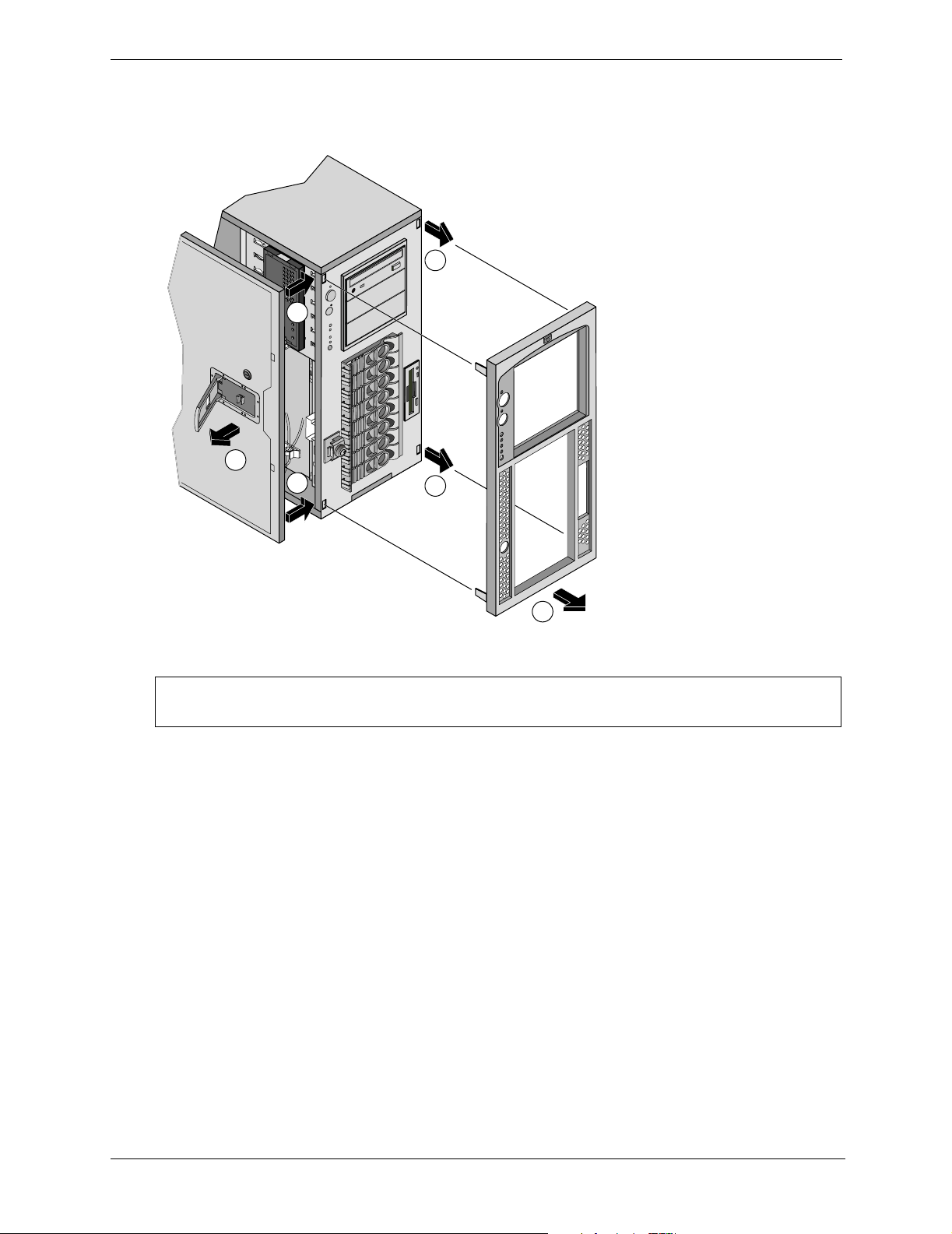
5. To remove the bezel, first remove the left cover by pulling the plastic latch out. Then press down the two
self-locking tabs to release the bezel. The right tabs slide out without removing the right cover. See
Figure 3-3.
Note:
in on two self-locking tabs to releas
Remove left cover and press
the bezel. Right tabs will slide out
without removing the right cover.
3
2
1
2
3
4
Figure 3-3. Removing the HP Server tc4100 Bezel
CAUTION To prevent damage to the covers, support the cover as you remove it from the HP Server
tc4100. The Server’s covers can be easily damaged.
6. If necessary, remove the right side cover by lifting the plastic latch.
The right cover only provides access to the Power Distribution Board and Floppy Disk Drive.
7. Pull the cover forward and then slightly sideways to disengage it.
8. Move it to the right and away from the chassis.
26
Page 29
Chapter 3 Installing and Configuring
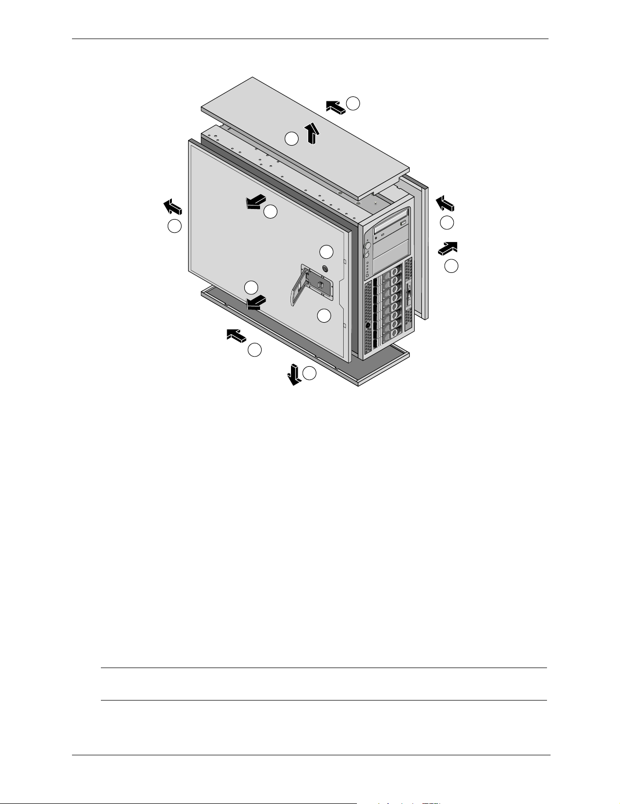
9. Remove top cover (only if necessary).
8a
7a
3
4
1
3
2
6
5
8
7
Figure 3-4. HP Server tc4100 Covers
10. To replace the left side cover, position the cover’s tabs next to the respective holes along the outer edge on
the side of the chassis.
11. Slide the cover toward the rear.
12. Close the plastic latch.
13. To replace the right side cover, position the cover’s tabs next to the respective holes along the outer edge
on each side of the chassis.
14. Slide the cover toward the rear.
15. Close the plastic latch.
16. To replace the bezel, insert the tabs at the bottom of the bezel into the slots on the chassis.
17. Swing the top of the bezel toward the chassis until it snaps into place.
Removing the Pedestal
The pedestal version of the HP Server tc4100 mounts to an anti-tip pedestal, which can be easily removed, if
necessary.
1. Perform Steps 1-4 in the previous section, “Removing Covers – Pedestal” on page 25.
NOTE The front bezel is shown removed, but the bezel may remain on the chassis while
removing the pedestal.
2. Disconnect all cables connected to the rear of the Server that would limit its rotation before continuing.
27
Page 30
Chapter 3 Installing and Configuring
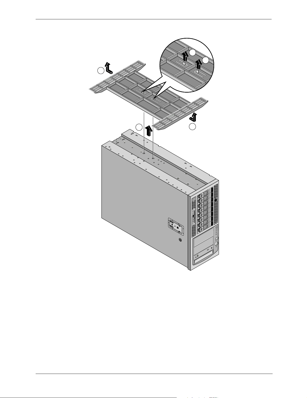
3. Turn the Server over onto its top and pull up on the two tabs as shown in Figure 3-5.
3
3
2
1
2
Figure 3-5. Removing the Pedestal
4. Slide the pedestal to the rear of the Server.
5. To re-install the pedestal, repeat Steps 1-3 and slide the pedestal forward onto the Server.
28
Page 31

Chapter 3 Installing and Configuring
Mass Storage Devices
Introduction
This section describes how to install the internal mass storage devices, including the internal SCSI Hot Swap
hard disk drives and Non-Hot Swap SCSI disk drives. The requirements for external SCSI drives are provided
in the respective topic later in this section.
NOTE The embedded dual channel SCSI controller operates as a LVD (Low-Voltage
Differential) controller, but if a SE(single-ended) device is connected to the controller, it
automatically switches to SE and all SCSI devices connected to the controller must
operate as SE devices. If your system was not configured with a backup tape drive, you
must use a terminated non-hot swap cable for the tape drive.
Installing Storage Devices After Shipment
If you are installing mass storage devices that were not shipped with your HP Server tc4100, certain
configurations may require additional cables or adapters not provided with your HP Server tc4100 shipment.
For part numbers of the required items, such as HP cables, adapters, trays, and configuration information, see
Information Assistant on the HP Server tc4100 Navigator CD-ROM.
For new products, you may use Order Assistant on the HP web site at:
http://www.hp.com
You may select “Buy HP” and choose the country and desired option that best suits your needs. You may also
download the Order Assistant utility.
Tools Required
Torx T-15 driver (non-Hot Swap devices)
Drive Bay Shelves
The non-hot swap drives include the IDE CD-ROM and the 3.5 inch flexible disk drives which are standard for
all HP Server tc4100 models and ship with each unit. The two empty drive shelves beneath the CD ROM drive
support other non-hot swap SCSI devices, such as hard drives, tape back-up devices, or other HP-tested (LVD
or SE) SCSI accessories.
29
Page 32

Chapter 3 Installing and Configuring
(
)
The system chassis ships with a Hot Swap Mass Storage cage supporting up to eight low-profile Hot Swap hard
drives.
Hot Swap
Hard Drives
(8 bays)
CD-ROM
Drive
i
Flexible Disk
Drive (Floppy)
Hard Drive
Lock
Non-hot-swap
Drives
optional
Figure 3-6. Standard Mass Storage Configuration
Boot Priority
This section details the HP Server tc4100’s boot order by highest to lowest priority. The on-board SCSI
controller has two channels, A and B. Channel B is typically used to control the Hot Swap SCSI drives. Channel
A is typically used to control the internal non-hot swap SCSI drives. On each SCSI channel, the Server scans
for a boot device starting at device ID 0 and proceeds up from there.
The HP Server tc4100’s boot order (BIOS search order for a boot device) should be considered, when
connecting cables from the on board SCSI channels.
By default the Server searches for boot devices in this order:
1. IDE CD-ROM drive
2. Flexible disk drive
3. SCSI A bus (typically non-Hot Swap internal SCSI devices)
4. SCSI B bus (typically Hot Swap Mass Storage Cage)
5. PCI Slot 6
6. PCI Slot 5
7. PCI slot 4
8. PCI slot 3
9. PCI slot 2
10. PCI slot 1
11. Embedded LAN
You can change this boot order using the Setup Utility (BIOS) by pressing F2 during the boot process, and the
SCSI Configuration Utility by pressing Ctrl-C during the boot process.
30
Page 33

Chapter 3 Installing and Configuring
Mass Storage Guidelines
• General Guidelines
• Use care when unpacking and handling the disk drives.
The hard disk drives are very susceptible to mechanical shock and can be easily damaged by a drop as
short as one-quarter of an inch. If the drop would crack an egg, it will damage the drive.
• Do not stack drives.
• Do not use high voltage differential (HVD) SCSI devices on any of the SCSI channels or damage will
occur. Use only Single-Ended (SE) or Low-Voltage Differential (LVD) devices.
• SCSI Device Selection
• Ensure that the SCSI devices you install in both Hot Swap and non-Hot Swap-drive bays do not have
terminations installed. The non-Hot Swap SCSI drives are connected to a terminated cable and the Hot
Swap cage provides the termination for all slots in the cage.
• Use only HP LVD SCSI 3.5-inch hard disk drives for the Hot Swap drive cage.
You can only use low-profile (1.0 inch) drives in the Hot Swap cage. Be sure to use filler panels to cover
any open slots. The HP Hot Swap drives come set for LVD SCSI operation and without device ID or
termination. Do not change these settings.
• Use only
3.5-inch or 5.25-inch SCSI devices for the non-Hot Swap shelves.
The available space in the non-Hot Swap shelves supports two half-height (1.6 inch) devices. You can
order HP mounting kits for removable media devices or trays for 3.5-inch hard disk drives (half-height).
You may use narrow/wide SCSI adapters on these devices.
• Use the SCSI Tape Drives specified in the “Selecting SCSI Tape Drives” on page 38.
• SCSI Drive Addressing
• The drives in the Hot Swap Cage are automatically assigned SCSI addresses by the HP Server tc4100.
The Hot Swap drive’s address is dependent on its position within the drive cage.
The Hot Swap Cage also supports the installation of an optional Duplex kit, which divides the cage in
two halves. The installation of a Duplex board does not change the SCSI addressing.
Slot ID Number
1 2 3 4 5 6 7 8
Duplex Split
SCSI
Channel B
SCSI
Channel A
SCSI ID Number 0 1 2 3 8 9 10 11
Figure 3-7. Hot Swap Device’s Addressing with Duplex Board Installed
• The non-hot swap SCSI devices may use SCSI IDs from 0 through 15, with the following restrictions:
31
Page 34

Chapter 3 Installing and Configuring
o Narrow SCSI devices must be addressed 0 through 6.
o Wide SCSI devices may be addressed 0 through 15, except for ID 7, which is held by the SCSI con-
troller.
The non-hot swap SCSI devices are all connected to the same cable, which is terminated and connected
to one SCSI controller. Each SCSI device connected to the non-hot swap device connector must have a
unique address.
• SCSI Device Installation Order
The order of hard drive installation is described below:
• In pedestal configuration, start from the bottom of the Hot Swap drive cage when adding hard drives in
the HP Server tc4100.
If you are using one or more filler panels, insert them at the top of the cage. These configurations may
use filler panels to close up the front of the Hot Swap mass storage cage. If there are gaps in the cage,
the drives may not receive the proper ventilation and could suffer thermal damage.
• In rack configuration, start from the left of the Hot Swap drive cage when adding hard drives in the HP
Server tc4100.
If you are using one or more filler panels, insert the panels on the right side of the drive cage. These
configurations may use filler panels to close up the front of the Hot Swap mass storage cage. If there are
gaps in the cage, the drives may not receive the proper ventilation and could suffer thermal damage.
• Filler Panels
• Ensure all empty slots in the Hot Swap drive cage have filler panels inserted to ensure proper airflow.
If there are fewer drives than the Hot Swap drive cage supports, a 1-inch filler panel must be inserted in
each empty disk location. The filler panels ensure the drive cage has the proper ventilation and airflow.
The filler panel will be removed before inserting a new drive.
CAUTION To prevent overheating or excessive electromagnetic radiation, use the filler panels to fill
the gaps between Hot Swap hard drives. If the filler panels are left out of the drive
shelves, thermal damage and/or excessive EMI could occur.
Cabling Configurations
CAUTION There are various SCSI cable configurations associated with the system and, if
incorrectly configured, could cause damage to the HP Server tc4100 and the SCSI
devices.
There are various SCSI cable configurations associated with the HP Server tc4100 and if all possible SCSI
devices and connections are used, then an additional SCSI disk controller is required. Table 3-2 describes the
various cables and where each one can be connected.
NOTE The correct cable routing of the hot-swap hard disk drive SCSI cable is having it connect
from either a PCI disk controller, or SCSI B on the system board to SCSI A on the hotswap hard disk drive backplane.
Do not connect the SCSI terminated cable # 3 (this cable is optional and must be purchased separately) to the
Hot Swap Mass Storage Cage's connector A or B, or unreliable operation will occur.
• The Hot Swap Mass Storage Cage can have up to eight drives with only one SCSI cable connected.
32
Page 35

Chapter 3 Installing and Configuring
• The Hot Swap Mass Storage Cage can also be split into two parts, with up to two drives on one SCSI bus
and 6 drives on the other SCSI bus (requires duplex board accessory kit). This requires two SCSI cables
(additional SCSI cables are included in the duplex board accessory kit).
If the duplex board is installed, the embedded dual channel SCSI controller, a dual channel SCSI disk
controller board, or a DAC board must be used to control the two halves of the Hot Swap Mass Storage
Cage.
Table 3-1. Internal Cable Designations
Cable Designation Description Source
Floppy Disk Cable This cable always connects to
the Flexible disk drive in the
This cable can only connect to the
floppy connector on the system board.
system.
IDE Cable This cable always connects to
the IDE devices (CD-ROM) in
the HP Server tc4100.
Round Twisted Pair SCSI Cable This cable always connects to
the non-hot swap drives and
has a termination at the end.
This cable can only connect to the
embedded IDE connector on the
system board.
This cable can be connected only to
the embedded SCSI A channel and a
PCI SCSI Card or a PCI HP NetRAID
card.
Flat Twisted Pair SCSI Cable This cable always connects to
the Hot Swap Mass Storage
Cage and has no termination.
This cable is typically connected to the
embedded SCSI B channel, a SCSI
disk controller board, or a HP
NetRAID (DAC) board.
Internal/External SCSI Cable This sheathed ribbon cable
(optional) is always used for
This cable can be connected only to
the embedded SCSI channel A.
the external connector.
33
Page 36

Chapter 3 Installing and Configuring
Main P
e
Rear Locator
Connector
Intrusion
Switch
Connector
Two 64 bit
PCI Slots
Four 32 bit
PCI Slots
ower
Cable
DIMM
(4 places)
Misc. Signal
Cable, To Power
Distribution Board
0123
Battery
SCSI A
2 1
Connector
SCSI B
1 2 3 4 5
Connector
6 5 4 3
IDE Cable
To CD Driv
To Floppy
Drive
To C o n t rol
Panel
DIP
Switch
Figure 3-8. SCSI Connectors for Hot-Swap and Non-Hot Swap Drives
34
Page 37

Chapter 3 Installing and Configuring
Installing Hot Swap Hard Drives
Use this section to install Hot Swap hard drives in the Hot Swap drive cage.
CAUTION Protect the drive from static electricity by leaving it in its antistatic bag until you are
ready to install it. Before handling the drive, touch any unpainted metal surface to
discharge static electricity. When you remove the drive from the antistatic bag, handle it
only by the frame.
Do not touch the electrical components. If you have to handle electrical components,
wear the antistatic strap. Place the drive on the antistatic bag whenever you set it down.
1. Ensure that the hard disk cage is unlocked, if it is locked, use the key to unlock it.
2. Remove the filler panel from the location you want the Hard Drive installed by simply pulling it straight out.
3. Open the drive module by pressing in on the locking latch at the center of the drive ejector handle and
pulling the handle open. See Figure 3-9.
2
1
3
Figure 3-9. Opening the Drive Module
CAUTION To prevent snapping off the handle do not use extreme force when opening it. Open the
handle until you feel resistance.
35
Page 38

Chapter 3 Installing and Configuring
4. Gently slide the drive module into the cage and stop when you feel resistance.
3
1
2
Figure 3-10. Inserting the Drive
5. Verify that the two pins behind the pivot end of the handle engage the holes in the edge of the cage.
6. Press the ejector handle in until you feel the latch click into place.
Closing the ejector handle engages the drive with the electrical connector in the Hot Swap drive cage and
seats the drive.
7. If the drive is unseated in the cage after closing the ejector handle, repeat this procedure from Steps 3 to 6.
The handle was probably not pulled out far enough, and the locking latch failed to engage the Hot Swap
mass storage cage.
NOTE Closing the ejector handle engages the drive with the electrical connector in the Hot
Swap mass storage cage and seats the drive.
Removing Hot Swap Hard Drives
CAUTION You must remove the drive slowly to ensure the drive heads are parked prior to removal.
Ensure that you follow these instructions carefully to prevent handling damage, such as
head slaps or head actuator unlocking.
1. To unlock the drive, push the locking latch in and then pull the ejector handle toward you.
2. Gently pull the drive out about an inch to disengage the power connection.
3. Wait about 30 seconds for the drive to stop spinning and the drive heads to park.
4. Use your hand to support the bottom of the drive, while you slowly pull the drive straight out.
Do not allow the drive to fall.
5. Place the drive in an electrostatic-protected container.
Do not stack drives.
36
Page 39

Chapter 3 Installing and Configuring
Installing Non-Hot Swap Storage Devices
Use this section to install any of the non-hot swap mass storage devices used as a hard drive or a tape backup
storage.
CAUTION Protect the drive from static electricity by leaving it in its antistatic bag until you are
ready to install it. Before handling the drive, touch any unpainted metal surface to
discharge static electricity. When you remove the drive from the antistatic bag, handle it
only by the frame.
Do not touch the electrical components. Place the drive on the antistatic bag whenever
you set it down.
CD-ROM Drive
Non-Hot-Swap
Hard Drive
(optional)
Floppy Drive
Figure 3-11. Non-Hot Swap Drive Shelves
To install a drive in the non-hot swap drive bay:
1. Shut down the HP Server tc4100’s NOS.
2. Disconnect the power cords.
3. If working on a pedestal-mounted Server, remove the covers and front bezel and gain access to the HP
Server tc4100’s non-hot swap-drive bays.
4. If working on a rack-mounted Server, follow the appropriate instructions to safely extend the Server from
the rack. Then remove the covers and front bezel.
5. Select an available drive bay for the device and remove the filler panel.
6. Configure the device according to the manufacturer’s instructions.
Refer to SCSI addressing in “Mass Storage Guidelines” on page 31.
7. If you are installing a boot device, check the boot priority described earlier in this chapter.
8. If the device does not already have a storage tray or mounting hardware, install the appropriate mounting
hardware on the device.
Refer to the directions included with the device’s mounting hardware.
9. Slide the drive into the open shelf.
37
Page 40

Chapter 3 Installing and Configuring
10. Connect the power cable and the appropriate data cable (SCSI) from the system board or SCSI controller
to the device.
11. The air flow guide, the fan assembly, and the fan cage may need to be removed to access the back of the
drive cage to connect the drive data and power cables.
12. Replace the cover(s) and front bezel.
13. If the Server is rack mounted, slide it back into the rack and secure it.
14. Return power to the Server and run the Setup Utility to configure the device.
Selecting SCSI Tape Drives
NOTE Tape drives do not come with the mounting hardware that is required for installation. Be
sure to order the appropriate mounting kit (HP product number Q1447A).
Table 3-2 lists the supported tape drive models with their respective part number, size (half height or full
height), and the Hp Server location in which the tapes are supported. Figure 3-12 displays linear drawings of
the HP Server tc4100 rack and pedestal versions with the locations for the different SCSI Tape Drive models.
UseFigure 3-12 to match the codes on the “Supported Location” column of Table 3-2.
Table 3-2. SCSI Tape Drives Specification
DRIVE Size Part No. Supported Location Comments
DLTVS 80i Half Height C7405A R1 or R2, P2 or P3 Use the plastic drive rails
when installing.
DAT 40i Half Height C56864A R1 or R2, P2 or P3 Use the plastic drive rails
when installing.
Ultrium 215i Half Height C7420A R1 or R2, P2 or P3 Use the metal drive rails
when installing on the server.
DAT 24i Half Height C1555D R1 or R2, P2 or P3 Use the metal drive rails
when installing on the server.
DAT 24x6i Full Height C5677B R1 and R2, P2 and P3
(Two HH slots are required)
Ultrium 230i Full Height C7400A R1 and R2, P2 and P3
(Two HH slots are required)
Use the metal drive rails
when installing on the server.
If this drive is installed in
position P2 or P3, it is
necessary to remove the
power protection bracket of
the server.
Drive will extend slightly
from the front of the server.
Use the metal drive rails
when installing on the server.
DAT 40x6i Full Height C5677A R1 and R2, P2 and P3
(Two HH slots are required)
If this drive is installed in
position P2 or P3, it is
necessary to remove the
power protection bracket of
the server.
Use the metal drive rails
when installing on the server.
38
Page 41

Chapter 3 Installing and Configuring
P1 CD-ROM
P2 Location
P3 Location
i
Pedestal Rack Mount
Figure 3-12. SCSI Tape Drives Supported Location
R1 Location
R2 Location
R3 CD-ROM
Connecting External SCSI Devices
An accessory can be ordered for the HP Server tc4100 which will provide an external SCSI connection from
the SCSI A connector embedded on the system board.
A SCSI disk controller board or a DAC board inserted into one of the PCI slots may also provide an external
SCSI connection. The last device in the SCSI chain of external devices must be terminated.
CAUTION Do not use high voltage differential (HVD) SCSI devices on any of the SCSI channels or
damage will occur. The HVD SCSI devices are not supported. Use only Single-Ended
(SE) or Low-Voltage Differential (LVD) devices to connect to the external connectors.
Memory Modules
Introduction
This section provides the instructions for installing and removing DIMMs on the system board in the HP Server
tc4100. The video memory comes with 8 MB standard and cannot be upgraded.
NOTE The EDO DIMMs and PC 100 SDRAM DIMMs from earlier HP Server tc4100 models
will fit into the DIMM slots in the Server, but the EDO DIMMs and PC 100 SDRAM will
not function properly. Use only 133 MHz SDRAM DIMMs acquired from HP.
To ensure you have the correct DIMMs before installation, refer to one of the following for a list of qualified
DIMMs:
• Technical Reference Label inside the HP Server tc4100’s top or side coverHP Order Assistant on the HP
web site at:
http://www.hp.com
• Information Assistant on the HP Server tc4100 Online Documentation
CD-ROM
• HP Customer Service
39
Page 42

Chapter 3 Installing and Configuring
M
d
(
)
Tools Required
Antistatic service kit (3M™ 8501/8502/8503 or equivalent). This kit includes a static-dissipating work surface,
a chassis clip lead, and a wrist strap.
Memory Installation Guidelines
• The HP Server tc4100 uses only 133 MHz (PC133) SDRAM DIMMs, which are electrically different from
the EDO and PC100 SDRAM memory modules used in other HP Server models.
• DIMMs sizes supported are 128 MB, 256 MB, 512 MB, or 1 GB in any combination.
• Supported memory capacity ranges from 128 MB to 4 GB maximum (1 GB per DIMM slot and 4 DIMM
slots total). The minimum capacity is 128 MB (one DIMM).
• DIMM sizes may be mixed on the system board and may be loaded in any order.
• Open slots between DIMMs are permitted.
• When handling DIMMs, observe antistatic precautions to avoid damage.
DIMM Installation
Use this procedure to install each DIMM in a DIMM slot on the system board.
emory Boar
(DIMM)
Notch
2 places
Figure 3-13. Individual SDRAM DIMM
CAUTION Do not install EDO DIMMs or PC100 SDRAM from other HP Serves models. Use only
DIMMs specified for this model.
To install additional memory in the HP Server tc4100:
1. To gain access to the HP Server tc4100, perform one of the procedures listed below.
NOTE It is not necessary to remove the system board from the HP Server tc4100 to install the
additional DIMM memory.
• If the Server is mounted on the pedestal, perform Steps 1-8 from “Removing Covers – Pedestal” on page
25.
• If the Server is in the rack, perform steps 1-14 from “Removing Covers – Rack-Mount” on page 21.
2. Remove Air Scoop.
40
Page 43

Chapter 3 Installing and Configuring
M
d
g
g
3. Locate the DIMM slot for installation and spread the two retaining clips outward. See Figure 3-14.
Notch
(2 places)
emory Boar
(DIMM)
Close Retainin
Latches
(2 places)
1
2
DIMM
Slot
Align Keys
2
Figure 3-14. Opening Retaining Clips
with Notches
(2 places)
4. Ensure retaining clips are open and then align the notches on the DIMM with the keys on the DIMM slot,
holding the DIMM at a 90° angle to the system board. Figure 3-14.
5. Insert the DIMM fully into the slot, handling the DIMM by its edges. See Figure 3-15.
The retaining clips should grasp the DIMM automatically if it is inserted properly. If the clips do not close,
the DIMM is not inserted correctly.
NOTE: Remove the air scoop first
by unhooking the latch on top to
release it from fan enclosure
then lift it up.
1
Air
Scoop
DIMM
3
2
2
Open
Retainin
Latches
(2 places)
Figure 3-15. Installing the DIMM
CAUTION Do not rock the DIMM into place, but apply firm and even pressure. If the retaining clips
do not close, remove the DIMM and repeat Steps 5-6
6. Re-install the Air Scoop.
41
Page 44

Chapter 3 Installing and Configuring
7. If all DIMMs have been installed, re-assemble the server.
Refer to “Opening and Closing the HP Server tc4100” on page 21
.
8. If the Server is in a rack installation, return the chassis into the rack.
9. Reconnect the power cord(s).
10. Power on the HP Server tc4100 according to the respective NOS power up instructions.
11. Return the HP Server tc4100 to normal operation.
42
Page 45

Chapter 3 Installing and Configuring
DIMM Removal
Use this procedure to remove DIMMs from the HP Server tc4100's system board. The HP Server tc4100 must
be powered down and the appropriate cover must be removed from the HP Server tc4100 before removing any
DIMMs.
1. If you have not already removed the appropriate cover from the HP Server tc4100, perform one of the
procedures listed below.
• If the Server is mounted on the pedestal, perform Steps 1-8 from “Removing Covers – Pedestal” on page
25.
• If the Server is in the rack, perform steps 1-14 from “Removing Covers – Rack-Mount” on page 21.
2. Remove the Air Scoop.
3. Select the desired DIMM(s) to remove.
4. Open the DIMM's retaining clips to lift the DIMM’s top edge away from the clips. See Figure 3-14.
5. Lift the DIMM completely away from the slot. See Figure 3-14.
6. Place the DIMM in its antistatic container.
7. Re-install the Air Scoop.
NOTE Ensure the retaining clips on the DIMM slots for each DIMM are closed before replacing
the cover onto the HP Server tc4100.
An error will be displayed if all DIMMs are removed.
8. If the Server is a rack installation, return the chassis into the rack.
Refer to “Opening and Closing the HP Server tc4100” on page 21.
9. Re-install the bezel onto the front of the HP Server tc4100.
Refer to “Opening and Closing the HP Server tc4100” on page 21.
10. Reconnect the power cord(s).
11. Power on the HP Server tc4100 according to the respective NOS power-up instructions.
Refer to Chapter 1‚ Control and Indicators.
12. Return the HP Server tc4100 to normal operation.
43
Page 46

Chapter 3 Installing and Configuring
Processors
Introduction
The HP Server tc4100 supports two processors that must operate at the same speed and cache size. Both
processors sockets are located on the system board.
The HP Server tc4100 supports the Pentium III processors at a front side bus (FSB) speed of 133 MHz.
Advanced processors may be supported as each one becomes available. Contact HP or your reseller for details.
The Server ships with one processor in the primary processor socket.
Tools Required
An antistatic service kit (3M™ 8501/8502/8503 or equivalent). This kit includes a static-dissipating work
surface, a chassis clip lead, and a wrist strap.
Processor Configuration Guidelines
The HP Server tc4100 supports a variety of processor speeds with an FSB speed of 133 MHz.
CAUTION Do not open the new processor's protective bag or remove it from the bag until you are
ready to install it.
Before you remove a processor from the antistatic container, touch a grounded, unpainted
metal surface on the HP Server tc4100 to discharge static electricity.
• Both processor modules must be the same processor type and have the same product number, which insures
the same clock speed, cache size, and FSB speed.
• The processor modules must operate at the designated speed stated by the product type on the processor.
CAUTION Do not set the processor speed switches to any other speed, as this can result in unreliable
or intermittent performance, and data integrity may also be at risk.
• Use only processor upgrade kits with the same HP product number. This ensures the processor type, clock
speed, and cache size match, and that product numbers are compatible.
• If you want to upgrade the primary processor, you do not have to remove the termination card.
44
Page 47

Chapter 3 Installing and Configuring
0123
2 1
1 2 3 4 5
6 5 4 3
Figure 3-16. System Board
Installing the Processor
The installation procedure is the same for the rack-mounted models as for the pedestal models of the Server
once you gain access to the system board.
CAUTION Use an antistatic wrist strap and a grounding mat.
Wear a wrist-strap and use a static-dissipating work surface connected to the chassis
when handling components. Ensure the metal of the wrist strap contacts your skin.
1. Unpack the processor shipping box and check the contents against its packing list.
CAUTION Do not remove the processor from its bag until you are ready to install it and ensure the
bag remains sealed until then
2. Gracefully shut down the network operating system according to directions in your NOS documentation.
3. Press the power switch on the HP Server tc4100's control panel when prompted by the operating system.
Normally, this completes the shutdown procedure.
4. Disconnect the power cords and any connected phone lines.
WARNING Power supplies will continue to provide standby current to the Server until the power
cords are disconnected.
5. To gain access to the system board, follow the appropriate instructions for removing the cover.
• If the Server is mounted on the pedestal, perform Steps 1-8 from the “Removing Covers – Pedestal” on
page 25.
45
Page 48

Chapter 3 Installing and Configuring
T
• If the Server is in the rack, perform steps 1-14 from “Removing Covers – Rack-Mount” on page 21.
NOTE It is not necessary to remove the system board from the Server to install the new
processor module.
6. Verify the processor speed and FSB setting, before installing the second processor module.
Both processor modules must have the same clock speed, cache size, FSB speed, and product number.
NOTE When installing a second processor, the processor speed is set automatically. No manual
setting of switches is necessary.
NOTE The System board is shown removed from the HP Server tc4100 for simplicity in the
following figures, but it is not necessary to remove the system board to install the new
processor module.
7. Remove the terminator from the secondary processor socket by lifting up the lever and pulling the
terminator upwards.
NOTE Save the terminator in the CPU protective bag for future needs.
erminator
2
1
Lift Up
Lever
Figure 3-17. Remove Terminator Board
46
Page 49

Chapter 3 Installing and Configuring
P
8. Remove the processor module from the sealed bag.
rocessor
Processor
Socket
Pin 1
Marker
Lower
Lever
2
Figure 3-18. Installing the Processor
1
9. Align the additional processor module over the secondary processor module socket by matching the corner
of the processor that has fewer pins with the corner of the socket that has fewer pins.
10. Gently push down on the processor module until it seats.
11. Lower the lever to completely seat the processor module firmly in the connector.
NOTE When you purchase an additional processor module, the package includes the heat sink
that sits on top of that processor. Also, the thermal grease is already applied to the bottom
of the heat sink.
12. To install the heat sink:
CAUTION Do not ingest or inhale the thermal grease (heat sink compound). Do not get it in your
eyes. Avoid prolonged skin contact, which can cause irritation. Wash with water any skin
that contacted thermal grease. If thermal grease gets in your eye, flush the eye with water.
If ingested, do not induce vomiting. Consult a physician.
NOTE When you purchase an additional processor module, the package includes the heat sink
that sits on top of that processor. Also, the thermal grease is already applied to the bottom
of the heat sink.
CAUTION Ensure you have made good contact with the processor to avoid thermal overheating. If
you have not made good contact with the processor, it will overheat within 20 seconds of
power on and will shut down.
• Apply a very small amount (the size of 1/2 grain of rice) of thermal grease to the center core of the
processor (the raised rectangle in the center of the processor).
47
Page 50

Chapter 3 Installing and Configuring
• Spread the grease carefully over the core using a single-edge razor blade or some other tool as long as
the tool is clean. Don’t allow the grease to spread beyond the edges of the core rectangle
• Center the heat sink properly over the additional processor
• Locate the bottom notched edge of the heat sink and, when placing the heat sink over the processor, be
sure that the notched edge faces the front panel of the HP Server tc4100.
CAUTION Minimize any twisting or lateral sliding when installing the heat sink on the processor.
Ensure you have made good contact with the processor to avoid thermal overheating. If
you have not made good contact with the processor, it will overheat within 20 seconds of
power on and will shut down.
Lower Clip Tab
To H o o k Latch
in Back
1
Unplug
Power Cord
Processor
4
2
Lower Clip Tab
5
To Hook Latch
in Front
3
Align Latch
holes with
processor
Socket tab
Tab
(2 places)
Figure 3-19. Installing Heat Sink
NOTE Before the processor heat sink can be latched on, the Air Scoop must be removed from
the fan wall. If you do not remove the Air Scoop, the front heat sink clip can not be
accessed.
13. Fasten the rear heat sink clip by matching the holes of the clips with the tabs of the socket.
14. Fasten the front heat sink clip in the same fashion.
15. Re-install the Air Scoop.
16. Re-install the cover and bezel onto the Server according to the appropriate procedure.
Refer to “Opening and Closing the HP Server tc4100” on page 21.
17. Return power to the Server and restore normal operation.
48
Page 51

Chapter 3 Installing and Configuring
Accessory Boards
Introduction
This section describes how to install accessory boards into the system board of the HP Server tc4100. The
system board provides up to six PCI slots (P1 through P6), two of which are 64-bit slots.
Tested PCI Boards
For a list of tested PCI boards, check for compatibility in Configuration Assistant on the Navigator CD-ROM
or look for the Hardware Tested Products list for the HP Server tc4100 under the Service and Support topic for
the specific NOS used in the Server at HP’s web site:
http://www.hp.com
CAUTION Some accessory board outputs may exceed U.S. National Electrical code (NFPA 70)
Class 2 or limited power source limits and must use appropriate interconnecting cabling
in accordance with the National Electrical Code. (All Hewlett Packard boards comply
with Class 2.)
Tools Required
The following tools are required for installation or removal of the accessories boards in the HP Server tc4100:
• An antistatic service kit (3M™ 8501/8502/8503 or equivalent). This kit includes a static-dissipating work
surface, a chassis clip lead, and a wrist strap with ground lead.
• Torx 15 screw driver.
HP Server Remote Management Card
The HP Server Remote Management Card has to be installed in slot 6. There is a 50-pin connector/cable that
should connect the HP Server Remote Management Card and the system board.
Boot Priority
This section details the HP Server tc4100’s boot order by highest to lowest priority. The Server’s boot order
(BIOS search order for a boot drive) should be considered when selecting a slot on the system board. This is
especially important if you are installing a SCSI disk controller board. The disk controller’s boot priority is set
by the board’s slot location.
The on-board SCSI consists of two channels, A and B. Channel B is typically used to control the Hot Swap
SCSI drives. Channel A is typically used to control the internal non-hot swap SCSI drives. On each SCSI
channel, the system scans for a boot device starting at device ID 0 and works up from there.
By default the Server searches for boot devices in this order:
1. IDE CD-ROM drive
2. Flexible disk drive
3. SCSI A bus (typically the non-Hot Swap internal SCSI devices)
4. SCSI B bus (typically the Hot Swap Mass Storage Cage)
5. PCI slot 6
6. PCI slot 5
7. PCI slot 4
8. PCI slot 3
49
Page 52

Chapter 3 Installing and Configuring
9. PCI slot 2
10. PCI slot 1
11. Embedded LAN
NOTE The Server can be configured to boot from a PCI accessory board or PCI-based DAC,
instead of the onboard SCSI channels, by putting the board in one of the PCI slots. The
SCSI Configuration Utility can be used to configure the Server to skip over the onboard
SCSI channels and select a PCI slot instead, when scanning for boot devices.
IRQ Settings
The IRQ settings are automatically assigned and do not require user intervention. PCI boards have the capability
to share hardware interrupts (IRQs) with other PCI boards, as stated in the PCI specifications, but this does not
always prove to be true between board manufacturers.
The HP Server tc4100 provides various ways to automatically share interrupts in the Server. The sharing mode
can be selected under the heading “Sharing Algorithms” in the Setup Utility. The IRQs are automatically
assigned during boot up for each PCI slot and embedded device in the Server, avoiding any IRQ conflicts and
providing the best performance. This feature also provides a way of manually assigning IRQs when disabling
the Sharing Algorithm feature.
These IRQ assignments trigger the installed NOS to enable the APIC (Advanced Programmable Interrupt
Controller), which takes control of the IRQ sharing scheme. You are not required to manually assign interrupts
for the following NOSs:
• Microsoft’s NT 4.0
• Novell’s NetWare 5
• SCO UnixWare 7
NOTE CO UnixWare 7 requires installation of the OSMP module to enable the APIC.
System Board PCI Slots
All accessory boards plug into the six slots on system board at the rear of the Server’s chassis.
• Four PCI slots (Slots 3 - 6) support full length 32-bit boards at a clock rate of 33 MHz. These slots only
support +5 VDC power and Universal boards. These slots have keys in the upper half of the board slot to
prevent 3.3 volt boards from being inserted into the slots.
NOTE Universal boards automatically switch to accept power from a +5.0 or +3.3 VDC source
and have a key slot in the connector to allow installation in any of the 6 PCI slots.
50
Page 53

Chapter 3 Installing and Configuring
• Two PCI slots (Slots 1 - 2) support full-length 32- or 64-bit boards at clock rates of 33 or 66 MHz. These
slots only support +3.3 VDC power and Universal boards. These slots have keys in the upper half of the
board slot to prevent 5volt boards from being inserted into the slots. See Figure 3-20.
0123
Two 64 bit
PCI Slots
2 1
Four 32 bit
PCI Slots
Figure 3-20. System Board PCI Slots
CAUTION Some accessory board outputs may exceed U.S. National Electrical code (NFPA 70)
Class 2 or limited power source limits and must use appropriate interconnect cabling in
accordance with the National Electrical Code.
Installing Accessory Boards
Use this procedure to install all accessory boards.
1. Read the documentation included with each board and follow any special instructions provided.
CAUTION To prevent a system crash, never remove or insert a PCI board from or into a slot with the
Server powered on. Always turn power off to the Server before performing any
installation or removal operations.
2. Log off all users and back up all files.
1 2 3 4 5
6 5 4 3
3. Follow the instructions in the respective NOS (network operating system) documentation to gracefully shut
down all networking software and applications.
4. Press the power button on the HP Server tc4100's control panel when prompted by the operating system.
Normally, this completes the shutdown procedure.
NOTE The power supplies will continue to provide standby current to the Server until the power
cord is disconnected.
5. Gain access to the Server by performing the appropriate procedure.
51
Page 54

Chapter 3 Installing and Configuring
• If the Server is mounted on the pedestal, perform Steps 1-8 from “Removing Covers – Pedestal” on page
25.
• If the Server is in the rack, perform steps 1-14 from “Removing Covers – Rack-Mount” on page 21.
6. Consider the boot priority before installing any accessory boards.
If installing a SCSI disk controller board, the controller’s priority (BIOS search order for a boot drive) is
set by the board’s slot location. For details, refer to Boot Priority earlier in this chapter.
7. Identify the desired slot (1 through 6), before installing the accessory board.
8. Remove the slot cover from the Server’s rear panel, before installing the new board into the slot, as shown
in Figure 3-21.
Screw Slot
Cover
Figure 3-21. Removing the Slot Cover.
NOTE Each PCI slot must have a slot cover or PCI board in the slot. Ensure that all unused slots
have slot covers.
CAUTION Do not bend the PCI board to install it into the slot. If a full-length PCI board has a handle
on the end of the board that prevents its installation, remove the handle before installing
the board.
9. Before installing the new PCI board:
• Verify there is no handle attached to it, especially if it is a full-length board.
• If it has a handle attached, remove the handle before installing the board into the slot.
10. Align the board with its slot along its full length and position it into the slot.
11. Push the PCI board down into its connector in the System board.
52
Page 55

Chapter 3 Installing and Configuring
S
12. Secure the PCI board as shown in Figure 3-22.
crew
1
PCI Card
(optional)
2
Figure 3-22. Installing the Accessory Board
13. If the installed accessory board requires an external connection or a connection to the System board, ensure
that the cable is properly attached.
Refer to the accessory board documentation for connection requirements.
14. If accessory board installation is complete, re-assemble the Server.
15. If all installation work is complete, return power to the Server according to the respective NOS power up
instructions.
16. Use the respective NOS software to ensure the correct software drivers for the PCI board are loaded and
verify correct operation.
53
Page 56

Chapter 3 Installing and Configuring
Configuring the HP Server tc4100
Introduction
This chapter supports setting up software on your HP Server tc4100. You may choose to do this before or after
you install the Server in the rack.
HP Server tc4100 Navigator CD-ROM
The HP Server tc4100 Navigator CD-ROM provides you with two choices for running the CD-ROM and
accessing its configuration information and utilities.
• Run the Navigator CD-ROM on the HP Server tc4100 in order to configure the tc4100 and HP Accessories
and to obtain the required configuration information and drivers needed to set up the Server.
You need to the run the Navigator CD-ROM on the Server to install the NOS and all the bundled drivers
and utilities. Refer to the following topics for the contents of Navigator's Main Menu when used on the
Server.
• Run the Navigator CD-ROM on any Windows PC after setting up the HP Server tc4100 to obtain the
required configuration information and create any needed NOS installation diskettes.
Refer to “Running the Navigator CD-ROM on a Windows PC” on page 67.
Contents of the Navigator CD-ROM – HP Server tc4100
The Main Menu directs you to modules where you can perform configuration tasks or create the diskettes
required for installation including the Utilities. The Information Assistant button directs you to the HP Server
tc4100 Online Documentation CD-ROM. The menu buttons are:
• Navigator Overview
Describes the functions and modes available when using the HP Server tc4100 Navigator program whether
at the server or client.
• What's new on the CD
Lists changes implemented in system BIOS, software and firmware since the last version of the CD.
• System README
Provides solutions to issues found after the system documentation was published.
• View Hardware Inventory
Lists details about the selected server, including installed hardware, system resources and firmware
versions.
• Change NOS Selection
Allows you to go back to reselect the Network Operating System to be used throughout your session.
System reselection may be done using the Toolbox.
• Configure the Server
• Guided Setup
Walks you through the steps required to setup and configure server hardware components (like the server's
hard disks, disk array, and remote management feature), and install the Network Operating System on your
server. HP recommended defaults and configuration advisories are provided where possible. A progress bar
is displayed at the bottom of the screen that tells you where you are in the process and status for each step.
• Custom Setup
54
Page 57

Chapter 3 Installing and Configuring
Allows you to select the individual steps provided in “Guided Setup” and perform them in your order of
preference. This menu is a subset of the tools available when you use the Toolbox. A progress bar at the
bottom of the screen tells you where you are in the process and status for each step.
• Replication Setup
Allows you to quickly clone the hardware configuration of one server to an identical server. Identical means
the same model, same hardware options. You will need the “Replication Diskette” created during the setup
and configuration of the original (source) server.
• Diskette Library
Provides a complete library of NOS drivers, utilities, and supplemental software for your server.
• HP Server Management Solutions
Lists and describes the additional management software available for your server and where to find it on
the CD.
• Troubleshooting
• FAQ
Frequently asked questions about using the HP Server tc4100 Navigator CD
• Diagnostic Diskette (Diagtools) Creation
Diagnostic tool for your server.
• Support Web Page
How to get additional support for your server via the web.
• Product Registration
Register your HP Server tc4100 and find out about the additional services HP offers to help keep your server
up and running.
Before the HP Navigator main menu is displayed, you may be prompted to set the language, time, and date. You
can also set the language displayed by the BIOS. Refer to the following topics for more information on the
Navigator CD-ROM's main menu items when run on the HP Server tc4100.
Obtaining HP Navigator CD-ROM Release Note
Check the release note to ensure you have the most recent firmware upgrades and software drivers for the HP
Server tc4100.
To ensure you have the latest versions of the HP Server tc4100 Navigator software, obtain the current HP
Server tc4100 Navigator CD-ROM Release Note. The Release Note is updated for each new release of the CDROM.
The Release Note briefly describes the following for each release:
• Major changes to the HP Navigator CD-ROM that were made for that release
• Version number
• Release date
You can read the Release Note for the HP Server Navigator CD-ROM via the What’s New Menu option. You
can obtain the Release Note for all HP Server Navigator CD-ROM’s from the HP support website at:
http://www.hp.com
55
Page 58

Chapter 3 Installing and Configuring
Obtaining Up-to-Date System Information
You can find up-to-date configuration information on the Navigator CD-ROM in the System Readme File. Use
this source to learn about applicable compatibility issues and get the latest information for configuring your
server.
Access the System Readme File First
This file includes the most recent information that was not included in the printed installation documentation.
Follow these steps to view the file when booting from the CD.
1. Press the power-on button.
2. Press the CD-ROM drive eject button.
3. Place the HP Server tc4100 Navigator CD-ROM in the drive and press the eject button again to close the
drive. The CD-ROM will start automatically, using the auto-run feature, as soon as the drive closes.
4. If the CD-ROM does not start automatically, push the reset button.
5. If the system fails to boot, follow the diagnostic instructions on the screen.
6. If the server boots the CD sucessfully, go to the HP Navigator main menu.
7. If the language needs to be changed, select User Preferences and the language you want. You can also
change the language of the BIOS, but this is only available when in the BIOS Setup Utility.
8. Select System Readme and read it carefully before beginning your installation.
The System Readme file contains the latest information to help you install your HP Server tc4100.
Server Configuration Utility
The Configure the Server utility guides you through the steps necessary to configure the HP Server tc4100. You
can view configuration advisories at one step and change your hardware if necessary.
Three methods of configuration are available: Guided , Custom, and Replication.
The HP Automated NOS Installation utility guides you through the NOS installation and configures the NOS
with the appropriate drivers for the HP-bundled configuration. If Navigator detects that a newer version of the
BIOS is available on the HP Navigator CD-ROM it will prompt you to update the BIOS.
Before you configure your server, you may need to run the Symbios Configuration utility and the Setup Utility
to do the following:
• If you need to verify or modify SCSI host adapter settings.
• If you need to low-level format SCSI disks or verify SCSI disk media, run the Symbios Configuration
utility.
Configuring the Server Using the Navigator CD-ROM
Power on the Server and Insert the HP Server tc4100 Navigator CD-ROM into the CD-ROM drive. If the system
fails to start, follow the instructions on the screen.
1. You may need to set the language, time, and date when the HP Server tc4100 Navigator starts.
2. If so, follow the on-screen instructions.
You can also change the language in which BIOS error messages are reported, but this is only available
when in the Setup Utility (BIOS).
3. Go to the HP Server tc4100 Navigator main menu and select Configure the Server.
4. Follow the on-screen instructions to continue the Server Installation.
56
Page 59

Chapter 3 Installing and Configuring
Guided Configuration
Guided configuration is the preferred method to configure your Server since it leads you through the
configuration process in sequence and offers you default selections. Guided configuration includes the
following steps:
1. Tested Configurations (Optional)
Presents information that should be viewed before configuring your system:
• Configuration Advisor (Recommended)
Lists caveats and exceptions based on your system, hardware installed, and NOS selection.
• Tested Products List (Optional)
Lists hardware and software products tested with HP Server systems.
2. BIOS and Firmware Update
Updates your server's BIOS code and firmware with the versions on the CD. This step will be automatically
skipped if there are no mismatches between the BIOS on the system and on the CD.
3. Disk Array Configuration
Allows you to run the disk array controllers (DAC) configuration utility. This step will be automatically
skipped if there are no DAC's detected in the system.
4. Remote Management Device Configuration (Optional)
Allows you to run the configuration utility for the Remote Management Device (RMD) in the system. This
step will be automatically skipped if is are no RMD detected in the system.
5. Diagtools Diskette Creation (Optional)
Takes you to the Diskette Library to create a Diagtools diskette.
6. Save Configuration to Diskette (Optional)
Allows you to save the current hardware configuration on to a diskette which can be used to replicate the
configuration on another HP Server.
• Select NOS:
You will be asked to select the NOS and version you plan to install.
• Select NOS Installation Mode:
For certain versions of Novell NetWare/IntranetWare and Microsoft Windows NT/2000 Server, you will
be asked:
Would you like to use HP's automated mode of NOS installation?
o Select Yes for automated NOS installation.
Perform an automated NOS installation for first-time installation of Novell NetWare/IntranetWare
or Microsoft Windows NT/2000 Server on a factory-configured Server. Automated NOS installation
will guide you through the NOS installation, set up the hard disk drive, and configure your NOS with
appropriate drivers for HP-bundled configurations.
This installation also loads Instant Toptools onto Widows NT/2000 or NetWare systems. Instant
Toptools is a stand-alone support tool accessed directly from the server. It gives you information to
help you manage the server.
Automated NOS Installation: For certain versions of Novell NetWare/IntranetWare or Microsoft
Windows NT/2000 Server, Configuration Assistant partitions and formats the hard disk drive, and
Installation Assistant guides you through the NOS installation and configures the NOS with the
appropriate drivers for the HP-bundled configuration.
o Select No for manual NOS installation.
Perform a manual NOS installation if you are installing a NOS other than certain versions of Novell
NetWare/IntranetWare or Microsoft Windows NT Server, or if you have replaced any HP
components.
57
Page 60

Chapter 3 Installing and Configuring
For Manual NOS Installation Only: Before you perform a manual NOS installation, you must print
instructions and manually create NOS-specific driver diskettes as follows:
¾ Create Drivers Diskette(s): On the Create Drivers Diskette(s) screen, select Create Drivers Dis-
kette(s) to create one or more customized diskettes containing HP drivers and configuration files
to use when you install the NOS.
¾ Print and Read Instructions: On the Show NOS Installation Instructions screen, select Save to
Disk to copy the Network Operating System Installation Instructions to disk. Then print them out
from the disk. Read the instructions first, and then follow them to manually install the NOS.
Custom Configuration
Only select Custom on the Configuration menu if you are experienced in Server configuration and have a
preferred sequence of steps, or if you prefer to configure your system one component at a time. In Custom
configuration mode, you perform the same configuration steps as provided in Guided configuration mode, but
these can be done in any order.
After you have selected the NOS, version, and NOS installation mode (automated or manual), and after you
have viewed the Configuration Advisories, the Custom Configuration screen displays the following menu:
Essential Steps
• Configure Disk Array:
This configures your HP disk array, but requires you to fill out the Disk Array Configuration Worksheet,
before proceeding. Click Help for more details.
• Execute Card Utilities:
This executes the available configuration utilities for installed cards.
• Create Drivers Diskette(s):
SCSI HP NetRaid Adapter and video adapter drivers for MS Windows NT 4.0 on HP Server tc4100s.
Recommended Steps
• Update System BIOS:
This utility will update the system BIOS. The utility partition, if installed, will also be updated.
• Install Utility Partition:
Installs utility partition to the boot or system drive. This is NOT available under SCO Unix.
• Show System Information:
Shows hardware inventory and system resource (interrupts, I/O space) allocation.
• Show NOS Installation Instructions:
Select this option to save a copy of NOS installation instructions to diskette and to print it out.
Replicate Configuration
In Replicate configuration mode, you can save a copy of your current system configuration or load a previously
saved configuration. This method saves time when configuring multiple, identical systems. Select Replicate on
the Configuration Assistant menu.
58
Page 61

Chapter 3 Installing and Configuring
NOS Installation
The NOS installation process, whether automated or manual, is the same in custom configuration mode as in
Express configuration mode:
• For Manual NOS Installation Only:
Before you perform a manual NOS installation, you must manually create NOS-specific drivers diskettes
and print instructions, as follows:
• Create Drivers Diskette(s): On the Create Drivers Diskette(s) screen, select Create Drivers Diskette(s)
to create one or more customized diskettes containing HP drivers and configuration files to use when
you install the NOS.
• Print and Read Instructions: You may already have done this directly from the Custom Configuration
menu option Show NOS Instructions. If not, on the Show NOS Installation Instructions screen, select
Save to Disk to copy the Network Operating System Installation Instructions to disk. Then print them
out from the disk. Read the instructions first and then follow them to manually install the NOS.
• Install NOS:
• Automated NOS Installation:
For certain versions of Novell NetWare/IntranetWare or Microsoft Windows NT Server, Configuration
Assistant partitions and formats the hard disk drive, and Installation Assistant guides you through the
NOS installation and configures the NOS with the appropriate drivers for the HP-bundled configuration.
• Manual NOS Installation:
Follow the instructions on the screen and the Network Operating System Installation Instructions that
you printed out.
HP Management Solutions
HP Management Solutions is a comprehensive suite of utilities, applications, and built-in features to manage
multiple HP Servers locally or from remote locations. If you are unfamiliar with these products or concepts:
• Go to the Management Web site on the HP Web Site at:
http://www.hp.com
to view information on HP Toptools and all other HP Server tc4100 management options for your Server.
• Read the HP Netserver/Server Management Reference Guide included with your Server. This guide covers
Toptools and all other HP Server tc4100 management utilities and options for the HP Server tc4100.
Toptools for Servers
HP Toptools for Servers is an online-reactive troubleshooting tool that displays the System Event Log (SEL)
and gathers configuration information from the system. It also serves as the diagnostic engine for
troubleshooting network servers through HP Instant Support.
Some of the features of Toptools include:
• Notification of problems with key hardware components including memory, disk drives, SCSI controllers,
NICs, and power supplies, as well as environmental problems with temperature and voltage
• Unified event log to review a complete history of HP Server tc4100 activity in one place
• Predictive disk problem warning backed by HP pre-failure warranty replacement
• Disk capacity threshold alert and usage tracking
• Viewing of critical HP Server tc4100 inventory information such as the BIOS version, driver and firmware
versions, PCI slot contents, and serial and parallel ports.
• Easy linkage with leading management platforms including HP OpenView Network Node Manager
59
Page 62

Chapter 3 Installing and Configuring
• Support for DMI 2.0, which provides the same Desktop Management Interface inventory information for
Servers as for desktop PCs
Toptools should be installed to help your service provider troubleshoot your system. Toptools is located on HP
Toptools CD-ROM included with the system.
• See the HP Server tc4100 Management Reference Guide for detailed installation instructions.
• You can also download the Toptools software and documentation from the Server Web Site at:
http://www.hp.com
HP Server Remote Management Card (Optional Accessory)
The Toptools for the HP Server Remote Management Card provides a management function for the HP Server
tc4100. It enables remote LAN or modem-based server management and alerting through a pager or e-mail for
improved remote administration of your Server.
Toptools Remote Control provides:
• Remote monitoring of critical HP Server tc4100 components, regardless of system state
• Access for troubleshooting and problem resolution, regardless of system state
• Pager or e-mail notification of critical HP Server tc4100 events to alert you to problems
• Access to the Event Log
• Server reset and power control
• Remote system BIOS or HP Server Remote Management Card
• Password and dial-back security
• Text console redirection of the HP Server tc4100 console
• Full graphics console redirection of Microsoft Windows NT Servers across the network or over a modem
connection using Symantec's pcANYWHERE software (included with the system).
See the HP Server Remote Management Card User Guide for details.
PcANYWHERE
pcANYWHERE is a remote-control graphics-redirection software from Symantec Corporation that allows you
to take control of Microsoft Windows NT Servers across the network or over a modem. Refer to the HP Server
tc4100 Online Documentation CD-ROM for details, or the HP Server Remote Management Card
User Guide.
ServerUtilities
HP Server tc4100 Utilities takes you to a menu where you can directly execute utilities such as the following:
• Diagtools: An easy-to-use hardware diagnostic for system verification, burn-in, and rapid troubleshooting.
NOTE HP recommends using the HP Diagtools utility to verify all Server functions are
operating correctly, after completing all the configuration topics. The HP Diagtools
utility also generates a text file containing the hardware detected and the Diagtools test
results. This text file, called a support ticket, should be saved to a diskette and used for
future reference, especially by your support provider.
• Event Log Report Utility: Displays all logged HP Server tc4100 management events, Power-On Self Test
(POST) errors and other system events (only if the HP Server Remote Management Card is installed).
60
Page 63

Chapter 3 Installing and Configuring
• Diskette Library: Allows you to conveniently generate a flexible diskette for any utility or driver available
on the HP Server tc4100 Navigator CD-ROM. For example, you can create flexible diskettes for the
following utilities and drivers (such as: BIOS Update, HP Diagtools, and NOS Drivers).
• Print or View Information: Allows you to print or view the current system configuration including details
of which boards are detected in the system and which resources are allocated to the boards.
• Change User Preferences: Lets you change the language used by the HP Navigator CD-ROM and the
system date and time.
Setup Utility
The HP Server tc4100 has a Setup Utility (BIOS) in read-only memory. The utility features several system
configuration and housekeeping options, including security, and system console characteristics.
The following sections describe how to access the Setup Utility and how to perform selected tasks.
Starting the Setup Utility
To reach the Setup Utility, boot or reboot the system. After the first boot messages are displayed, this prompt
appears:
Press <F2> to enter SETUP
Press F2 while the prompt is displayed. More boot messages appear, followed by the message Entering Setup...
After the embedded (Symbios) SCSI Configuration initialization and the Optional ROM scan both finish, the
menu bar of the Setup Utility appears.
If you do not press F2, the HP Server tc4100 boots normally.
Menu Bar
The Setup Utility provides a menu bar that leads to several menus. The menu bar choices are:
• Configuration – Sets the system time and date and has the following menus:
• Integrated I/O Port Settings – Use this menu to enable/disable and then set the base I/O address and IRQs
of the serial ports, Serial A, and Serial B port and set the parallel port's parameters, including its mode
(output only, bi-directional, or DMA channel).
• PCI Device Settings – Use this menu to disable the Sharing Algorithm for each slot and manually set the
IRQ for each PCI board installed into the six slots. This menu also includes setting the IRQ Locking
feature for the embedded SCSI channels and the embedded LAN connection. Three more IRQs can be
made available by disabling the Parallel, Serial A, and Serial B Ports.
• Boot Settings – Use this menu to check the flexible disk drive, display the Server's configuration at boot
time, skip certain tests during the boot process to speed up boot time, or change the (default) boot order,
including device type, network boot, and hard drive boot order.
• Embedded LAN & SCSI Settings – Use this menu to set the embedded NIC to enable, disable, or enable
as a boot device (Boot ROM Enabled). If the embedded NIC is enabled as a boot device, boot ROMs for
enabled SCSI devices cannot be loaded. This menu also enables/disables the Wake-On-LAN feature.
• Keyboard & Mouse Settings – Use this menu to set the parameters of the keyboard, including NumLock,
and set the PS/2 mouse to Auto (detect)/Enabled/Disabled. Disabling the mouse frees up IRQ 12, but
prevents any installed PS/2 mouse from functioning.
• Flexible Disk & IDE Settings – Use this menu to change the flexible disk type and IDE settings of the
HP Server tc4100's configuration. This would include selecting the hard drive's characteristics, manually
or automatically, and selecting which drive would be the Primary Master or Slave.
• Processor/Memory Settings – Use this menu to select if the processor module's serial number (if
supported) will be read by firmware, enables memory caching, and adds an extended memory gap in
system address space.
61
Page 64

Chapter 3 Installing and Configuring
• Security – Provides two submenus to choose from.
• Power-On Password – Sets the administrator and user passwords, setting system to require a password
after booting.
The Administrator password must be set before setting the User password. Once the administrator
password is set, the administrator can access and change all fields in the screens.
If the User password is set, the user may only change the system time, date, and user password. The user
may view all fields, but cannot alter any of the settings.
• Hardware Security – Sets the system parameters for input device operation, including copying sensitive
data and boot security.
• Exit – Exit the Setup Utility by saving changes or exit without saving changes, which reverts to previous
settings.
When you exit, the HP Server tc4100 reboots.
Using the Setup Screens
Online help explains the settings displayed on the Setup Utility screens. Instructions are also provided for
navigating between the screens and entering or changing the setup data.
• Press the right-arrow and left-arrow keys to move between selections on the menu bar. The menu bar is
present at the top of the main selections.
• Press the up-arrow and down-arrow keys to move between fields on each screen. The currently-selected
field is highlighted.
• Certain fields ask you to choose from a list of entries. In such cases, press the plus (+) or minus (-) keys
repeatedly to display each possible entry, or the Enter (or Return) key to choose from a pop-up menu.
• Small arrow points (¾) precede some field names. This means the field is actually a submenu. To visit the
submenu, select it with the arrow keys and press the Enter key. The submenu then appears in place of the
current screen.
• The Esc key is the exit key. If you press the Esc key on one of the top-level screens, the Exit menu appears.
If you press Esc on a submenu, the previous screen appears. When you are making selections from a popup menu, use the Esc key to close the pop-up without making a selection.
Changing the System Date and Time
Use this topic to change the HP Server tc4100's date and time and refer to the following procedure.
1. To reach the Setup Utility, boot or reboot the system and press F2 when prompted.
2. If necessary, use the left-arrow key to select Configuration from the menu bar at the top of the screen.
Once in the Setup Utility, the menu bar appears at the top of the screen with “Configuration, Security, and
Exit” shown. The Configuration menu is the default menu and should be the highlighted selection at the left
of the menu bar when the Setup Utility first opens.
3. If necessary, use the up-arrow key to move to the System Time field.
The “System Time” field is highlighted by default when the “Configuration” menu is selected. This field
actually consists of three sub-fields enclosed in brackets [xx:xx:xx]: hours to the left (24-hour clock),
minutes in the middle, and seconds to the right.
4. Type in the hour and press Enter to move to the minutes field.
5. Then type in the minutes and press Enter again to move to the seconds field.
6. Type in the seconds and press Enter, then use the arrow keys to leave this field.
7. Scroll to System Date field to enter the system date in the field.
62
Page 65

Chapter 3 Installing and Configuring
The dates are entered in the “System Date” field in the same way as the time is entered in the “System Time”
field. This field also has three separate sub-fields for month, day, and year enclosed in brackets [xx/xx/
xxxx].
8. Type in the month and press Enter to move to the day field.
9. Then type in the day and press Enter again to move to the year field.
10. Type in the year and press Enter, and then use the arrow keys to leave this field.
11. Use the right-arrow or left-arrow key to select the Exit menu.
12. Choose Exit Saving Changes from the list of exit options, then press Enter.
A dialog appears and asks you to confirm your decision.
13. Choose Yes and then press Enter.
The HP Server tc4100 reboots.
Setting the HP Server tc4100's Boot Passwords
Use this topic to set a password to boot the HP Server tc4100. You can have a separate administrator password
and a user password, but the user password is limited in access once booted.
To configure the HP Server tc4100 for passwords and require a password on boot-up, refer to the following
procedure.
1. If not already in the Setup Utility, boot or reboot the system and press F2 when prompted.
2. Use the right-arrow or left-arrow key to select Security from the menu bar.
As soon as it is selected, the selections for the Security menu appear as shown below.
• Power-On Password
• Hardware Security
The arrowhead > indicates there is a submenu to select from.
3. If necessary, use the arrow key to move to the Power-On Password menu selection and press Enter.
The Power-On Password is highlighted by default when the Security menu is selected.
The first line in the menu is, “Administrator Password is [Set or Not Set]”
• If no password has been set, then “Not Set” will appear in the field. If this is the case, then you are not
allowed to make any other selections in this menu, until you set an Administrator Password.
The Administrator Password controls access to the Setup Utility and its settings. The User Password has
only limited access to the Setup Utility, such as Date, Time, and Password.
• If “Set” is in the field, then you can change the password or make other selections in the menu. However,
you must start with the User Password, but may choose to skip setting the User Password.
NOTE You must set the Administrator Password before changing a User Password or
configuring the HP Server tc4100 to boot with a password.
4. Press the Enter key to enter a new password or change the old one.
A pop-up menu appears titled, “Set Power-On Password”. If no password has been entered, the field “Enter
New Password: [ ]” is highlighted. If a previous password has been entered, the field “Enter Old
Password: [ ]” is highlighted.
5. Enter the password (new or old) in the appropriate field and press Enter.
The password is accepted and the next field just below it, “Re-Enter New Password: [ ]” or “Enter New
Password: [ ]” field is highlighted. For security reasons, the password does not appear on the screen.
6. If necessary, enter the new password in the “Enter New Password: [ ]” field.
63
Page 66

Chapter 3 Installing and Configuring
7. Enter the new password again in the “Re-Enter New Password: [ ]” field.
After re-entering the new password a pop-up menu displays asking you to confirm your selection.
NOTE To leave the pop-up menu without entering a password, press the Esc key at any time.
8. Choose Yes and then press the Enter key.
The “Administrator Password is” field changes to “Set” and on the next boot the HP Server tc4100 will
request a password to access the Setup Utility.
9. If you want a password on boot up, you may skip the “User Password is:”field and go directly to”Network
Server Mode: [Disabled]” in Step 10.
10. If you want to enter a User Password, use the arrow keys to move to the “User Password is:” field and repeat
Steps 3-7 for the User Password.
11. Use the arrow keys to move to the “Network Server Mode: [Disabled]” field.
12. Press Enter to toggle [Disabled] to “Enabled” in the Network Server Mode field.
Setting this mode to Enabled will cause the HP Server tc4100 to prompt for a password when booting from
a diskette or a CD-ROM, but will not require a password when booting from a hard drive. The power-switch
and keyboard will remain locked until the password is typed.
13. To use the front panel keyboard lock button, use the arrow keys to move to the “Keyboard Lock [Disabled]”
field.
14. Press Enter to toggle [Disabled] to “Enabled” in the Keyboard Lock [Disabled] field.
Setting this feature enables the keyboard lock button on the front bezel of the HP Server tc4100. Once
enabled, pressing the keyboard lock button will lock the keyboard and mouse until the password is typed.
You must set the password before enabling this feature.
15. To use the Hardware Security menu under Security, use the help files provided with the selections.
16. Select the Esc key to exit this menu.
17. Use the right-arrow key to go to the Exit menu.
18. Choose Exit Saving Changes from the list of exit options, and then press Enter.
A dialog appears and asks you to confirm your decision.
19. Choose Yes and then press the Enter key.
Then the HP Server tc4100 reboots.
20. To change one of the passwords at a later date, return to the Security menu and repeat Steps 2 through 7
above for one or both passwords.
NOTE The HP Server tc4100 allows you to reset the password by toggling a switch, position 3,
in the Configuration Switch Block on the System board.
Changing Internal Device Boot Priority
You can change the boot priority of the HP Server tc4100’s internal mass storage devices: the CD-ROM, the
flexible disk drive (or other removable device), and hard drives connected to the HP Server tc4100’s internal
SCSI ports.
1. Select “Boot Settings” from the Configuration menu, using the down-arrow or up-arrow key, and press
Enter.
A Boot Settings screen appears, very similar to the one below.
64
Page 67

Chapter 3 Installing and Configuring
Floppy check:[Disabled]
Summary screen:[Enabled]
Quick Boot mode:[Enabled]
> Boot Device Priority
> Hard Drive Priority
2. Use the down-arrow key to move to the “Boot Device Priority” field.
3. Press Enter to change the order and a list appears very similar to the one below:
1. [CD-ROM]
2. [Flexible Disk]
3. [Hard Drive]
4. [Network Boot]
The list provides the current boot order of the internal device types, including a NIC in the HP Server tc4100
connected to a network with a boot prom. If the [Hard Drive] selection is moved to the top of the boot list,
it will use the logical hard drive selected in Steps 5-6 to boot the system.
a. To change the order, use the up- and down-arrow keys to select one of the device types.
b. Use the plus (+) or minus (-) keys to move a device type up or down the list.
3. Press Esc to exit one level to the Boot Settings menu.
This moves you back one level to the Boot Settings list shown in Step 1 above.
4. To change the hard driver boot order, scroll to “Hard Drive Priority” and press Enter.
A hard drive (HD) boot list similar to the one below appears on screen depending on the hard drives and
bootable cards (DAC or SCSI Disk Controller) boards installed. The system attempts to boot the NOS on
the first hard disk drive (or DAC or SCSI board) found in this list. If no NOS is found, the system tries the
next logical hard drive in the list until a NOS is found.
1. [Bootable Cards]
2. [#30 ID01 LUN0 HP 4.26GB A]
3. [#30 ID02 LUN0 HP 4.26GB A]
5. Use the plus (+) or minus (-) keys to move the desired hard drive (or DAC or SCSI board) to the top of the
list.
• The HD boot list has a maximum capacity of eight (8) logical hard drives.
• If a bootable Disk Array Controller (DAC) or SCSI Disk Controller board is used, the board is seen as
a single logical drive.
• If more than eight logical drives are connected to the HP Server tc4100, drives 9 and above (including
the DAC or SCSI boards and the drives connected to each) will not be recognized by the Setup Utility.
• You will not be able to enter the Setup Utility to make changes to these logical drives (including DAC
and SCSI boards) during the boot process.
• However, these logical hard drives (including DAC and SCSI boards) will be properly recognized and
activated by the respective NOS.
• For more information about selection guidelines, refer to Information Assistant on the HP Server tc4100
Online Documentation CD-ROM.
6. Press Esc to exit the Hard Drive Priority menu.
7. Press Esc again to exit the Boot Settings menu.
8. Use the right-arrow key to select the Exit menu.
9. Choose “Exit Saving Changes” from the list of exit options, then press Enter.
A dialog appears asking you to confirm your decision.
65
Page 68

Chapter 3 Installing and Configuring
O
10. Choose “Yes” and press Enter.
Then the HP Server tc4100 reboots.
Clearing CMOS
The Setup Utility provides a method of clearing CMOS from within the Utility. You may alsoclear the CMOS
of the configuration settings using the configuration switch on the system board.
Clearing CMOS via the Setup Utility
1. To clear CMOS from the BIOS Setup utility, press F11 during server POST when prompted to “Press F2
to enter Setup”. This will provide advanced features in the Setup utility.
2. From the Exit menu, select “Clear system configuration”.
3. Press F10 to save and exit the utility.
Clearing CMOS via the System Board Switches
1. To clear CMOS configurations using the System Board switch, power down the HP Server tc4100 and open
the side panel to gain access to the System Board.
2. On the system board, reset switch 4, on the configuration switch block, from Off (open) to On (closed). See
Figure 3-23 and Table 3-3.
pen = Off
Closed = On
1
2
OPEN
Shaded rectangle
represents the
position of slide switch
3
4
5
6
7
8
Figure 3-23. Configuration Switch Block - Clearing CMOS
Table 3-3. Configuration Switch Block
Switch Number Switch On Switch Off
1 Not Used Not Used
2 Not Used Not Used
3
4
Clear Password
Clear CMOS
Keep Password
Keep CMOS
5 Not Used Not Used
6 Not Used Not Used
7 Not Used Not Used
8 Not Used Not Used
3. Power up the HP Server tc4100.
4. When you see a message diaplayed indicating that the configurations have been cleared, power off the HP
Server tc4100.
66
Page 69

Chapter 3 Installing and Configuring
5. Return switch 4 from On (closed) to Off (open) on the system board's configuration switch block. See
Figure 3-23.
6. Replace the side panel and power up the HP Server tc4100.
7. When you see the message “Incorrect System Configuration”, press F2 to run the Setup utility.
8. Make any configuration changes required.
9. Choose the Exit option and save the changes you just made and exit the utility.
SCSI Configuration Utility
If you need to verify or modify SCSI host adapter settings, or if you need to
low-level format SCSI disks or verify SCSI disk media, run the Symbios Configuration utility:
1. Turn on or reboot your system.
2. During system start-up or reset, when the following message appears, press the CTRL and C keys at the
same time.
Press [Ctrl] [C] to start Symbios Configuration Utility
3. Use the arrow keys to move the cursor, press Enter to select an option, and press Esc to exit.
4. To change adapter settings:
• Select an adapter from the list in the main menu.
• Select Adapter Setup. This option configures the SCSI ID setting and other advanced adapter settings.
5. To format a hard disk or change hard disk parameters:
• Select an adapter from the list in the main menu.
• Select Device Selections.
• Select the hard disk to format.
• Select the Format menu option.
For more information, refer to “Information Assistant” on the HP Server tc4100 Online Documentation CDROM.
Running the Navigator CD-ROM on a Windows PC
Using the HP Navigator CD-ROM in any Windows PC does not allow you to perform any configuration tasks,
but it does allow you to view the configuration instructions before or after installing and setting up your HP
Server tc4100. The Navigator CD-ROM will autorun on any PC with Windows 95
Windows NT
.
Contents of the Navigator CD-ROM – Windows PC
The Main Menu provides you with options to view and print configuration information. The menu and submenu
buttons are listed here with a brief description for each selection.
• What's New on the CD – This menu selection provides the part number and version of the CD as well as a
status report about the systems supported by this CD. It also provides the Internet address for the latest
information including release notes about your HP Server tc4100.
, Windows 98, or
• System README – This file includes the most recent information that was not included in the printed
installation documentation.
• Guide To Configure Server – This menu selection provides three submenus.
• NOS Installation Instructions - This submenu selection provides you with the necessary instructions to
install the NOS you have selected for this installation.
67
Page 70

Chapter 3 Installing and Configuring
• Tested Configurations – This menu selection provides two submenus.
o Configuration Advisor – This submenu option provides you with important information about such
items as driver version compatibility for various hardware and software items, such as NIC and
LAN boards or NOS drivers, workarounds for known configuration problems, etc. which will help
you complete your installation.
o Tested Products List – This submenu option provides you with a list of tested products for the HP
Server tc4100.
• Diskette Library – This menu selection provides the same listing of Utilities for the tc4100 as the
Diskette Library in the main menu. You may use this screen to create the required diskettes for “BIOS
Update Diskette – tc4100,” or utilities such as “HP Diagtools.”
• Diskette Library – This menu selection provides the same listing of Utilities for the tc4100 as the Diskette
Library submenu option under “Guide to Configure Server.” You may use this screen to create the required
diskettes for “BIOS Update Diskette – tc4100,” or utilities such as “HP Diagtools.” This menu selection is
the same one offered by the Navigator CD-ROM if run on the HP Server tc4100.
• Troubleshooting – This menu selection provides three submenu items.
• FAQ (Frequently Asked Questions) – This submenu covers the most often asked questions regarding
your HP Server tc4100 and its installation.
• Diagtools Diskette – This submenu helps you create the Diagtools Diskette.
• Support Web Page – This submenu option takes you directly to the HP Support web page if your PC has
an Internet connection and a browser. If not, it provides you with the current Internet address for HP
Support.
• Product Registration - This menu selection opens the Internet connection for registering your HP Server
tc4100 and its installation, if your PC has an Internet connection and a browser.
• HP Server tc4100 Management Solutions – This menu selection provides you with a comprehensive suite
of utilities, applications, and built-in features to manage multiple HP Servers locally or from remote
locations. This menu selection is the same one offered by the Navigator CD-ROM if run on the HP Server
tc4100.
Up-to-Date Configuration Details
You can find up-to-date configuration information on the HP Server tc4100Navigator CD-ROM, in “What's
New on the CD,” in “System README,” or in “Guide to Configure Server.” Use these sources to learn about
applicable compatibility issues and get the latest list of HP-tested peripherals and accessories. Refer to the Test
Products List in Configuration Advisor.
These files include the most recent information that was not included in the printed installation documentation.
Refer to following procedure to view these files.
1. Ensure the PC is powered on.
2. Press the CD-ROM drive eject button.
3. Place the HP Server tc4100 Navigator CD-ROM in the drive, and press the eject button again to close the
drive.
The CD-ROM will start automatically using the auto-run feature as soon as the drive closes.
4. If the CD-ROM does not start automatically, push the eject button on the CD drive and re-insert the CDROM.
5. The opening screen of the HP Navigator prompts you to select a HP Server model.
6. Select the HP Server tc4100 from the pull down list of Server models.
7. Press the Continue arrow icon at the bottom right of the screen.
The next screen appears prompting you to select a NOS (Network Operating System).
68
Page 71

Chapter 3 Installing and Configuring
8. Scroll down through the list of supported NOS and selected the NOS used with this installation.
The HP Navigator main menu appears.
9. Scroll to “What's New on the CD” in the main menu and read it carefully before beginning your installation.
You may also use the two icons to “Save to Diskette” or “Print” the information on screen.
10. Close the screen and scroll to “System README” and read it carefully or select to save or print it before
beginning your installation.
The System README file contains the latest information to help you install your HP Server tc4100.
11. Access the other Menu items as required, such as “Configuration Advisor” under “Guide to Configure
Server.”
The screens may display all or some of the following icons at the bottom of the screen.
• Exit – This icon allow you to exit the HP Navigator Program.
• Toolbox – This icon allows you to launch tools and utilities.
• Overview – This icon allow you to view configuration details.
• Help – This icon displays online help for the screen displayed or item selected.
• Home – This icon allows you to return to the main menu from your present screen.
• Back – This icon allows you to return to the previous screen.
• Continue – This icon allows you to continue to the next screen or with the currently selected process.
• Save to Diskette – This icon allows you to save the contents of the file displayed on screen.
• Print – This icon allows you to print the contents of the file displayed on screen.
• Close – This icon allows you to close the screen without taking any actions.
69
Page 72

4 Error Messages
Power-On Self Test (POST) Error Codes
Error messages (POST Codes) are encountered if an error condition occurs during the boot process of the HP
Server tc4100. All codes and their respective descriptions are listed in the following table; all the codes may
not apply to your server.
These codes will appear on the display monitor, provided it and the supporting circuitry are functioning.
NOTE Do not take remove/replacement actions until you have taken other troubleshooting
steps. See “Preventive Maintenance” on page 83.
Table 4-1. POST Error Codes
Code Description Problem/Solution
0000 System Board error POST has detected a failure limited to the system board internal
functions.
To verify this error:
1. Reboot the server.
Skipping this error message and continuing may result in unstable
behavior, or a system hang during the boot process.
2. If this error continues, the system board may need to be replaced.
Contact your service representative.
0010 BIOS problem The PC configuration has been lost, cleared, corrupted, or has not
been initialized. When the HP Server remains unplugged for a long
period of time, the battery will discharge and not provide enough
current to keep the CMOS memory powered.
To correct this:
1. Verify the battery is properly inserted.
2. 2. If necessary, replace the battery as described in your user's
guide.
Run the Setup Utility to re-configure your server.
0011 Battery problem The server BIOS is not responding due to a possible battery discharge.
If the HP Server was unplugged for a long period of time, the battery
will discharge and not provide enough current to keep the system date
and time current.
To correct this:
1. Verify the battery is properly inserted.
2. If necessary, replace the battery.
3. Set time and date using the Setup utility or from your operating
system.
0012 BIOS initialization
problem
0050 Processor Cooling/
Heating problem
The HP Server configuration has been cleared or has not been
initialized.
Run the Setup Utility to re-configure your system.
POST has detected a cooling fan problem.
70
Page 73

Chapter 4 Error Messages
Table 4-1. POST Error Codes
Code Description Problem/Solution
0100 Keyboard error during
POST
A key on the keyboard has been pressed during POST of the HP
Server.
To correct this:
1. Ensure nothing is placed on the keyboard and no key is accidentally pressed down.
2. Reboot the server.
3. If the error persists, your keyboard may need to be replaced. Contact your service representative.
0101 Keyboard error The keyboard has reported an error during its self-test.
To correct this:
1. Restart your HP Server.
2. If the error persists, your keyboard may need to be replaced. Contact your service representative.
0102 Keyboard controller
error
POST has detected a general failure in the integrated keyboard
controller.
To verify this error:
1. Restart your HP Server.
2. If the error persists, your keyboard may need to be replaced. Contact your service representative.
0103 Keyboard is not
connected
POST has detected the keyboard is not connected.
To correct this:
1. Verify the keyboard connector is firmly connected.
2. Reboot the server.
3. If the problem persists, your keyboard cable may be damaged or
your keyboard may need to be replaced. Contact your service representative.
0105 Mouse boot error The system board has detected a mouse error during POST.
To correct this:
1. Clean the mouse and its moving ball as described in the User's
Guide.
2. If the problem persists, your mouse may need to be replaced. Contact your service representative.
0106 Mouse is not
responding
The system board has detected the mouse is not responding.
To correct this:
1. If the mouse has just been removed, press Esc to automatically
validate the change.
2. Otherwise, verify the mouse connector is firmly connected.
3. If the problem persists, your mouse may need to be replaced. Contact your service representative.
0108 Mouse and Keyboard
connections reversed
POST has detected the mouse and keyboard connections are reversed.
To correct this:
1. Turn the server off.
2. Swap the mouse and keyboard connections.
3. Turn on the server power and reboot the server.
71
Page 74

Chapter 4 Error Messages
Table 4-1. POST Error Codes
Code Description Problem/Solution
0200 Serial Port Controller
resource conflict
POST has detected an address space or IRQ resource conflict between
one of the integrated serial port controllers and an accessory board.
To correct this:
1. If an integrated serial port is not needed, run the Setup Utility and
disable the related serial port.
2. If the integrated serial port is needed and its settings cannot be
modified, the accessory board's IRQ and address space must be
reconfigured to use other free resources. Refer to the accessory
board installation manual for information.
0201 Parallel Port Controller
resource conflict
POST has detected an address space or IRQ resource conflict between
the integrated parallel port controller and an accessory board.
To correct this:
1. If the integrated parallel port is not needed, run the Setup Utility
and disable the parallel port.
2. If the integrated parallel port is needed and its settings cannot be
modified, the accessory board's IRQ and address space must be
reconfigured to use other free resources. Refer to the accessory
board installation manual for information.
0300 Flexible disk drive (A)
boot error
POST has detected the flexible disk drive (A) reported an error during
its self-test.
To correct this:
1. Verify a diskette can be properly inserted and removed from the
flexible disk drive.
2. Verify the flexible drive type configured in the Setup utility
matches the flexible disk drive installed in the HP Server.
3. Verify all data cables and power cables are firmly connected.
4. If the problem persists, your flexible disk drive may need to be
replaced. Contact your service representative.
0306 Flexible disk drive
controller boot error
POST has detected a general failure on the integrated flexible disk
controller.
To verify this:
1. Restart your HP Server.
2. If the error persists, your system board may need to be replaced.
Contact your service representative.
0307 Flexible disk drive
controller resource
conflict
POST has detected an address space or IRQ resources conflict
between the integrated flexible disk controller and an accessory
board.
To correct this:
1. If the integrated flexible disk controller is not needed, run the
Setup Utility and disable the flexible disk controller.
2. If the integrated flexible disk controller is needed, the accessory
board's IRQ and address space must be reconfigured to use other
free resources. Refer to the accessory board installation manual
for information.
72
Page 75

Chapter 4 Error Messages
Table 4-1. POST Error Codes
Code Description Problem/Solution
0400 CD-ROM boot error POST has detected the CD-ROM drive has reported an error during
its self-test.
To correct this:
1. If a CD-ROM disk is present, verify it is correctly inserted.
2. Verify the CD-ROM drive door or tray has not been opened or
closed during the self-test.
3. Verify all data cables and power cables are firmly connected.
4. If the problem persists, your CD-ROM drive may need to be
replaced. Contact your service representative.
0401 CD-ROM drive not
responding
POST has detected the CD-ROM drive is not responding, but is
configured in the Setup utility.
To correct this:
1. If the CD-ROM drive has just been removed, press F4 to automatically validate the change.
2. Verify all data cables and power cables are firmly connected.
3. If the cable is damaged, connect the CD-ROM to another cable, if
available. The Setup Utility and the 32-bit disk access driver may
need to be modified accordingly.
4. If the problem persists, your CD-ROM drive may need to be
replaced. Contact your service representative.
0500 Hard Disk (primary)
controller boot error
POST has detected a general failure on the integrated (primary) hard
disk controller.
To correct this:
1. Restart your HP Server.
2. If the error persists, your system board may need to be replaced.
Contact your service representative.
053X Hard Disk drive
connection problem
(This does not apply to
tc4100)
(Error code #0530 is
the primary channel
cable IDE1 and #0531
is the secondary
channel cable IDE2)
POST has detected a hard disk drive on the second (slave) position on
the IDE cable, but no hard disk has been found on the first (master)
position.
To correct this:
1. If only one hard disk is connected on the cable, disconnect the
hard drive and use the other connector to re-connect the hard drive
into the first (master) position.
2. If two disks are connected on the cable, verify all data cables and
power cables are firmly connected for both hard disk drives.
3. If the error message appears just after a hard disk drive installation, check for master/slave specific jumper configurations in the
hard disk drive installation manual.
4. If the problem persists, the hard disk drive may need to be
replaced. Contact your service representative.
73
Page 76

Chapter 4 Error Messages
Table 4-1. POST Error Codes
Code Description Problem/Solution
0540 Hard Disk Controller
resource conflict
POST has detected an address space or IRQ resource conflict between
the integrated hard disk controller and an accessory board.
To correct this:
1. If the integrated hard disk controller is not needed, run the Setup
Utility to disable it (primary or secondary).
2. If the integrated hard disk controller is needed, the accessory
board's IRQ and address space must be reconfigured to use other
free resources. Refer to the accessory board installation manual
for information.
0600 Video Memory boot
error
(This does not apply to
tc4100)
The video memory size detected during POST is smaller than
previously detected.
To correct this:
1. If you have changed your video adapter, press F4 to automatically
validate the change.
2. If the problem persists, the system board may need to be replaced.
Contact your service representative.
0700 DIMM size boot error The system memory size detected during the POST is smaller than
previously detected. One or several DIMMs are either disconnected,
or have been replaced by smaller ones.
To correct this:
1. If some main DIMMs have just been removed or replaced by
smaller ones, press F4 to automatically validate the change.
2. If no DIMM has been removed or changed, ensure all DIMMs are
properly inserted in the slots.
3. If the problem persists, one of DIMMs may need to be replaced.
Contact your service representative.
0712 DIMM installation
error
POST has detected an incorrectly installed DIMM or the failure of
one or more DIMMs.
To correct this:
1. If additional memory was just installed in your server, please verify the installation conforms to the description in the User's Guide.
2. If this error was reported when no additional memory was just
installed, restart the server.
3. If the error persists, contact your service representative.
0713 Incorrect DIMM
installed
POST has detected one or more DIMMs are not the correct type, or
the correct speed.
To correct this:
1. If additional memory was just installed in your server, please verify the correct DIMM type and speed for this server was installed.
Refer to the DIMM description in “Memory Modules” in Chapter
3, “Installing TC4100.”
2. If this error was reported when no additional memory was just
installed, restart the server.
3. If the error persists, contact your service representative.
74
Page 77

Chapter 4 Error Messages
Table 4-1. POST Error Codes
Code Description Problem/Solution
0800 Cache memory size
error
POST has detected the cache memory size is smaller than previously
detected.
To correct this:
1. If the processor module has just been replaced, press F4 to automatically validate the change.
2. If the problem persists, the processor module may need to be
replaced.
0801 Cache boot error POST has detected an error in the cache memory module.
To correct this:
1. Verify the processor module is installed correctly. Refer to “Memory Modules” in Chapter 3, “Installing TC4100 “ for handling precautions.
2. If the problem persists, the processor module may need to be
replaced.
0900 Integrated LAN disable
error
The system could not disable the integrated LAN.
To correct this:
1. Reset the Integrated LAN by powering off the HP Server.
2. Disconnecting the power cord for 20 seconds.
3. Reconnect the power cord and power on the HP Server.
4. If the error appears upon restarting, update the system BIOS.
5. Insert the HP Navigator CD-ROM in the CD-ROM drive and
power-cycle your system.
This will initialize the flash utility on HP Navigator CD-ROM.
6. If the error persists, the system board may need to be replaced.
Contact your service representative.
0901 Integrated LAN enable
error
The system could not enable the integrated LAN.
To correct this:
1. Reset the Integrated LAN by powering off the HP Server.
2. Disconnecting the power cord for 20 seconds.
3. Reconnect the power cord and power on the HP Server.
4. If the error appears upon restarting, update the system BIOS.
5. Insert the HP Navigator CD-ROM in the CD-ROM drive and
power-cycle your system.
This will initialize the flash utility on the HP Navigator CD-ROM.
6. If the error persists, the system board may need to be replaced.
Contact your service representative.
0A00 Display refresh rate
error
The parameters returned by the display do not match the DDC
standard used by the server for automatic setup of ergonomic refresh
rates.
To correct this:
1. Disable the 'Plug & Play Display' feature in the Setup Utility to
avoid a blank or unreadable screen at power-up.
2. Use the Setup Utility to manually set the video refresh rates to the
highest ergonomic refresh rates supported by the display. Refer to
display monitor's User's Guide for specifications.
75
Page 78

Chapter 4 Error Messages
Table 4-1. POST Error Codes
Code Description Problem/Solution
0B0x Missing Microcode
Update
0B1x Failed to load
Microcode Update
0B2x Defective Microcode
Update
0B3x Processor Module
conflict
Your system is missing the Microcode Update data block for the
microprocessor.
You must correct this problem in order to avoid possible malfunction
or reliability problems.
To correct this:
1. Update your BIOS by running the flash utility from your Navigator CD-ROM. To do this, insert the Navigator CD-ROM in the
CD-ROM drive and power-cycle your system.
2. If updating your BIOS does not clear this error, contact your service representative.
Your system has failed to load the Microcode Update data block for
the microprocessor.
You must correct this problem in order to avoid possible malfunction
or reliability problems.
To correct this:
1. Update your BIOS by running the flash utility from your Navigator CD-ROM. To do this, insert the Navigator CD-ROM in the
CD-ROM drive and power-cycle your system.
2. If updating your BIOS does not clear this error, contact your service representative.
The Microcode Update data block for the microprocessor is defective.
To correct this:
1. Update your BIOS by running the flash utility from your Navigator CD-ROM. To do this, insert the Navigator CD-ROM in the
CD-ROM drive and power-cycle your system.
2. If updating your BIOS does not clear this error, contact your service representative.
POST has detected the processor modules installed in the server are
not the same type or speed.
To correct this:
1. Ensure both processor modules in the server have the same product code, which should include the type, heat sink, and speed.
2. If not, replace one or both to ensure both are the same product
code.
This problem must be corrected to avoid possible malfunction or
reliability problems.
Beep Codes
If the Bios detects a terminal error condition, it halts POST after issuing a terminal error beep code and it
attempts to display the error code on the upper left corner of the screen. The following is a list of the beep codes
issued for terminal errors.
Table 4-2. Beep Codes
Beeps POST Routine Description
1-2-2-3 BIOS ROM checksum
1-3-1-1 Test DRAM refresh
76
Page 79

Chapter 4 Error Messages
Table 4-2. Beep Codes
Beeps POST Routine Description
1-3-1-3 Test 8742 Keyboard Controller
1-3-4-1 RAM failure on address line xxxx*
1-3-4-3 RAM failure on data bits xxxx* of low byte of memory bus
2-1-2-3 Check ROM copyright notice
2-2-3-1 Test for unexpected interrupts
1-2 Search for ROMs. One long, two short beeps on checksum failure
1 One short beep before boot
*If the BIOS detects RAM error, it displays an additional word-bitmap (xxxx) indicating the address line or bits that failed.
77
Page 80

5 Diagnostics
When the server boots, a series of tests are displayed on the screen. The number of tests displayed depends on
the configuration of the server. The following are the kinds of errors a user might get with the HP Server.
• Built-in diagnostic error messages.
• BIOS and other error messages. These are errors detected by the system BIOS outside the built-in
diagnostics or application errors.
To see the Power On Self-Tests (POST):
• The HP Server must be functionally able to run the diagnostics.
• The video subsystem must be functional.
• The keyboard must be functional.
NOTE BIOS ROM version number is displayed on the monitor screen during power-up.
Power-On Self Test (POST)
The diagnostics Power-On Self Tests (POSTs) run automatically each time the server is powered on. These
diagnostics, which reside in the BIOS ROM, isolate server-related logic failures and indicate the board or
component that needs to be replaced, as indicated by the error messages. Most server hardware failures will be
accurately isolated by the diagnostic.
WARNING You should always turn off the power and disconnect the power cord(s) to the server
before opening the HP Server tc 4100 and attempting to remove the cover and touching
the internal components. Failing to do so can expose you to electric shock and the
server's components to damage. The power switch does NOT turn off standby power, so
disconnect the power cord(s) to turn off standby power.
There are two kinds of error messages that appear during the POST process and the causes of these messages
may prevent the server from completing the boot process. These are:
• Messages in reverse video (black text on white background).
Press the Return key to see a definition of the message and what action to take to remedy the problem.
• Power-on self test (POST) errors - These display in normal video (white text on black background) and may
be a text message or an alpha-numeric code. If an error with a text message occurs during the POST, details
of the error are displayed. Follow the instructions on the screen. If an alpha-numeric code appears, refer to
the section “Power On Self Test (POST) Error Codes” later in this chapter.
No Error Messages Displayed
General Checks:
1. All external cables and power cords are firmly plugged in.
2. The power outlet is working.
3. The server and monitor are turned on. (The power-on indicator should be illuminated.)
4. The display’s contrast and brightness settings are correct.
5. All internal cables are properly connected and all boards firmly seated.
78
Page 81

Chapter 5 Diagnostics
6. Verify that the processor and its heat sink are fully seated in its socket on the system board.
7. Verify that the memory is installed correctly and fully seated.
8. Verify the slots and tabs are aligned in the DIMM connector.
After Installing an Accessory:
1. Turn off the monitor, the server, and any external devices.
2. Unplug all power cords from the power outlet.
3. Open the side panel.
4. Check the following:
• If you have installed an accessory board, verify that the board is firmly seated in its slot and any switches
or jumpers on the accessory board are properly set.
• Refer to the documentation provided with the accessory board.
• Check all internal cabling and connections.
• If you have changed any switches on the system board, verify that each one is properly set.
5. Close the side panel and connect all cables.
6. Turn on the monitor and server.
7. If the server still does not work:
• Repeat steps 1, 2, and 3 of this section.
• Remove all accessories, except the primary boot hard disk drive.
• Close the side panel and connect all cables.
• Turn on the monitor and the server.
• If the server now works, replace the boards and accessories one at a time to determine which one is
causing the problem.
POST Error Messages
If you get a POST text error message in reverse video, press Enter (View System Error) to get a more detailed
explanation and a possible solution.
If the server starts, but POST still reports an error message, clear the CMOS configuration, as described later in
this chapter.
NOTE HP recommends you correct the error before proceeding, even if the server appears to
start successfully.
79
Page 82

Chapter 5 Diagnostics
Table 5-1 describes typical POST text errors and the corrective action you may take to remedy the problem.
Table 5-1. POST Error Messages
Message Corrective Action
Operating system not found • Verify that the desired boot drive has power and its SCSI cable is
connected.
• Verify that the SCSI cable is securely plugged into the SCSI
connector on the system board.
• Verify that the boot device is enabled in the Setup Utility under the
Security menu.
• Verify that the boot device has an operating system installed.
If the problem persists, contact your HP support organization.
Keyboard error Verify that the keyboard is connected to the correct connector (not the
mouse connector) at the rear of the server.
If the problem persists, replace the keyboard or contact your HP support
organization.
Mouse error Verify that the mouse is connected to the correct connector (not the
keyboard connector) at the rear of the server.
If the problem persists, replace the mouse or contact your HP support
organization.
If no message appears (screen is
blank)
If a configuration error occurs If a server configuration error is reported during the startup routine,
System CMOS checksum bad • Press F2 to run Setup.
• If no text or messages appear listen for the beep codes. Refer to the
Service manual on the HP Server Online Documentation CD-ROM.
• If no message appears but the server stops after POST, verify that the
DIMMs are correctly installed.
clear the CMOS memory as described under “Clearing the CMOS
Configuration,” and restart the server.
• Change settings as required.
• Choose the Exit option, selecting Save Changes and Exit to save the
new settings.
The server should reboot.
HP Server Diagtools
The purpose of hardware diagnostic software is to provide tools for checking hardware problems. By design,
diagnostic software executes simple tests of each hardware component. Usually, such tests assure that hardware
is not the source of server problems. This allows the user to eliminate hardware as the cause of the problem and
to focus on operating system configuration parameters, network connections, and application software
configuration parameters as the source of the problem.
If hardware problems are confirmed, the diagnostic software program can sometimes detect and diagnose the
subsystem or specific server component causing the problem. In addition, diagnostic tools can capture
information that allows support personnel to quickly assess the condition of the server.
In order to be effective, diagnostic software tools must be used in the context of a wider troubleshooting
procedure.
Diagtools for HP Servers is a set of offline diagnostic tests, including tests for system and processor
components, memory and storage elements, ports, and input/output devices. Diagtools is supplied on the HP
StartUp CD-ROM.
80
Page 83

Chapter 5 Diagnostics
The user prepares Diagtools software for use by transferring it to a diskette. Then the Diagtools diskette is used
to boot the server. A basic suite of tools checks key server components, and a menu of advanced tests is
available for in-depth testing.
Diagtools has the ability to test the following components:
• system board • processors
• memory modules • hard disk drives
• flexible disk drives • keyboards
• parallel ports • CD-ROM drives
• video monitor
Diagtools is an offline diagnostic. Offline diagnostics do not use the main operating system (OS) of the HP
Server. The alternate Diagtools OS has far fewer features than the full-fledged OS. Thus, its capabilities are
limited to a set of basic tests and a series of advanced tests. In addition, Diagtools does not use any tests which
might write over and thus destroy user data. Tests that require user inputs or decisions are left to the advanced
series of tests.
You can use Diagtools to perform the tasks listed below:
• Display a high-level inventory of the server under test
• Save and print a detailed inventory of hardware components
• Conduct a basic test of components listed in the server inventory
• Display “PASSED” or “FAILED” overall results of basic tests
• Record detailed test results of basic server tests
• Display a menu of advanced tests
• Select and run one or a series of advanced tests
• Add the record of results of advanced tests to the record of basic tests
• View a list to locate the meaning of a specific error code
• View one or more steps to help confirm and isolate error conditions
• Browse the support ticket, which contains the detailed inventories and test results
• Add comments to the support ticket
About Error Messages
A hexadecimal number designates each error message reported by Diagtools; a short note on the type of error;
and a list of one or more steps the user can take in response. When you run a test, it exercises many aspects of
the hardware, so the number of possible error messages exceeds 300. Most of these are encountered rarely, if
ever.
Error codes can be viewed online from the Diagtools User menu within the advanced series of tests, or you can
refer to Chapter 3 of the HP Server Diagtools Error Reference and User Guide.
Advantages and Limitations of Hardware Diagnostics
Offline diagnostic software is useful in making sure that hardware has been eliminated as the cause for possible
server problems. Such diagnostic tools can easily be shipped with a server, and they are relatively easy to use.
Only experienced personnel knowledgeable of its limitations should use offline diagnostic software.
Some limitations are:
81
Page 84

Chapter 5 Diagnostics
• Booting the server from the diagnostics diskette
• No access to operating system error logs, since the OS is not operating at the same time as the diagnostic
tools
• Limited ability to test only a single component at a time
• Inability to indicate problems with wrongly configured servers or the network
HP Toptools
HP Instant Toptools for Servers is an online-reactive troubleshooting tool that displays the System Event Log
(SEL) and gathers configuration information from the system. It also serves as the diagnostic engine for
troubleshooting network servers through HP Instant Support.
Toptools provides vital information for the fastest troubleshooting and proactive management of your HP
Servers. Processors, memory, storage, and NICs are a few examples of the components managed by Toptools.
Toptools is included with every HP Server and should be installed to help your service provider troubleshoot
your HP Server. Toptools is located on the HP Toptools CD-ROM.
For sites with a single-server installation, you may not need the power of the web-based HP Toptools. Instead,
HP Toptools Auto Alert and HP Instant Toptools, included on the HP Server Navigator CD-ROM can provide
all the tools you need to manage your small business environment. HP Instant Toptools provides the same
information as HP Toptools but is run directly at the server. HP Instant Toptools is automatically installed on
your server when using the HP Server Navigator CD to install your Network Operating System. HP Toptools
Auto Alert may be installed either from the HP Toptools CD-ROM or the HP Server Navigator CD-ROM.
• See the HP Server Management Reference Guide for detailed installation instructions.
• You can also download the Toptools software and documentation from the Toptools Web Site at:
http://www.hp.com
Some of the features of Toptools include:
• Notification of problems with key hardware components, including memory, disk drives, SCSI controllers,
and NICs
• Unified event log to review a complete history of server activity in one place
• Predictive disk problem warning backed by HP's pre-failure warranty replacement
• Disk capacity threshold alert and usage tracking
• View of critical server inventory information, such as the BIOS version, driver and firmware versions, PCI
slot contents, and serial and parallel ports
• Easy linkage with leading management platforms, including HP OpenView Network Node Manager and
computer Associates' Unicenter TNG and Tivoli products
• HP Toptools AutoAlert provides proactive warning of problems and advice on quick resolution through a
friendly “traffic light” user interface
• Support for DMI 2.0, which provides the same Desktop Management Interface inventory information for
servers as for desktop PCs
82
Page 85

6 Troubleshooting
Preventive Maintenance
Refer to this table for preventive maintenance procedures for this HP Server tc4100. Be sure to turn off power
to the HP Server tc4100 when cleaning it.
Table 6-1. Preventative Maintenance Procedures
Component Time Frame Maintenance Procedure
Keyboard Regularly Dust with a damp, lint-free cloth. Lock the keyboard if
there is that option on the HP Server; otherwise, power
off the HP Server before cleaning.
Monitor screen Regularly Use HP Video Screen Cleaner or other appropriate
monitor screen cleaner.
Mouse Regularly The ring surrounding the trackball on the bottom of the
mouse opens and closes. Remove the ring and keep the
trackball free of dirt. Do not use solvent to clean. Use a
damp, lint-free cloth.
Tape drive heads Monthly Use the recommended cleaning method noted in the
device’s manual.
Cooling fans and grilles 6 Months Check functions of cooling fans and clean the intake
openings on the chassis. Be sure to power off and
unplug the HP Server before cleaning. Use an industrial
static-free vacuum cleaner to remove the dust and lint.
CAUTION Do NOT use petroleum-based cleaners (such as lighter fluid) or cleaners containing
benzene, trichlorethylene, ammonia, dilute ammonia, or acetone. These chemicals could
damage the keyboard's plastic surfaces.
HP recommends the periodic cleaning of tape drive heads, capstans, and guides on the HP tape drive units and
those products using high-density data cartridges and mini-data cartridges. This maintenance procedure
prolongs tape and head life and helps reduce read/write errors due to dust and oxide. Call the HP Customer
Support Center or check HP’s Storage website for further information for preventative maintenance
information on the HP tape drive.
Troubleshooting Tools
If you are having problems installing your HP Server, there are a number of tools available for troubleshooting.
The HP Server Online Documentation CD-ROM contains the following tools:
• Troubleshooting Information
• Parts Information
• List of Error Messages
• List of Beep Code Error Messages
HP Server Navigator CD-ROM (only available for specific HP Server models) provides several utilities for
troubleshooting purposes. At the Main Menu, select “Server Utilities” to use the following tools:
• Diskette Library - A collection of diskette images representing drivers, utilities, and BIOS updates, which
enables you to conveniently generate any flexible disk available on the HP Server Navigator CD-ROM.
83
Page 86

Chapter 6 Troubleshooting
• HP DiagTools Utility - An easy-to-use hardware diagnostic for HP Server verification and rapid
troubleshooting. Use this image to copy DiagTools to two (2) flexible diskettes from the HP Server
Navigator CD-ROM.
• The Startup CD-ROM (only available for the HP Server tc2100 and tc2110) also provides the same
DiagTools utility for troubleshooting purposes: Boot to the HP Startup CD-Rom on the HP Server and
execute the utility. The HP DiagTools Utility will automatically launch.
Got to HP’s web site at www.hp.com to access the most comprehensive support material.
• Latest support news – Product and support information on HP Servers.
• Drivers and software downloads for HP Servers.
• HP Instant Support – Fast, web-based support that is automated and provides quick diagnosis and resolution
of most computing problems.
• Step-by-step guides and documents on the Instant Support site for system troubleshooting and information.
• Technical information – Data sheets, application notes, configuration guides, installation tips, product
papers, reference material and more.
• Compatibility Information – HP Accessories, OS/NOS, HP and third-party products.
• Manuals – Easy installation and configuration manuals for the HP Server.
• Parts and Service – Information on replacement parts, exploded views, and configuration.
• Tape backup support – Support for HP’s SureStore Tape Backup products.
Other Support Information
• HP Server Registration
• Training Programs – HP STAR worldwide training and certification program.
• Warranty and enhanced services – Your guide to services for your HP Server.
• Proactive Notification – HP will email your customer information when it is available.
• Contacts – How to get help or provide feedback.
If you need assistance, HP recommends contacting your reseller or going to the HP website first. Refer to the
topics listed above. If you need immediate telephone assistance, contact the HP Customer Support Center by
referring to the list of telephone numbers in the HP Server Warranty and Service/Support booklet provided with
the HP Server.
84
Page 87

Chapter 6 Troubleshooting
Troubleshooting
WARNING Before removing a cover, always disconnect the AC power cords. Disconnect them to
avoid exposure to high energy levels that may cause burns when parts are short-circuited
by metal objects such as tools or jewelry. Disconnect the telephone cables to avoid
exposure to shock hazard from the telephone ringing voltages.
WARNING Do NOT operate the HP Server for more than 10 minutes with any cover (including
power supplies and disk drives) removed. Otherwise, damage to system components may
result due to improper cooling airflow. However, you can safely remove a cover while the
HP Server is running to remove and replace PCI hot-plug boards. For any other service
activity requiring access to the system board or power distribution board, power down the
HP Server and observe all safety precautions.
• For problems with the HP NetRAID controller, refer to the appropriate HP NetRAID manuals.
• For general information on management products and for problems with HP Toptools, refer to the HP Web
Site at:
http://www.hp.com/toptools
• For general information on HP Server products, refer to:
www.hp.com and search for the specific product. These instructions do not generally cover third-party
components or devices. Refer to the documentation that comes with the third-party device for diagnostic and
troubleshooting information.
CAUTION Always wear an antistatic wrist guard when working inside the HP Server.
• Ensure the HP Server is properly configured. Many HP Server problems are the result of incorrect system
and SCSI subsystem configuration settings.
• Check the system BIOS Setup Utility by pressing F2 during the boot process.
• Check the SCSI configuration or the disk array configuration by entering the controller’s setup utility.
• Boot to the HP Server Navigator CD or Startup CD for access to configuration tools to help setup the HP
Server.
• If it is a network-related error, determine if the user has enough memory and hard disk drive capacity. Run
the diagnostics for the NIC. Consult with the network operating system manual.
• If it is a hardware error, follow the instructions to log users off the LAN and power down the HP Server.
Reboot and watch for any POST error messages and listen for any beep codes as the HP Server goes through
POST then look up the error message in Chapter 5 of this Service manual. If the HP Server passes POST,
the HP DiagTools Utility can be used to further test the hardware.
• Use HP DiagTools Utility whenever possible to detect hardware problems. Insert the HP Startup CD-ROM
into the CD-ROM drive and reboot the HP Server. Run HP DiagTools from the Startup CD-ROM and verify
the Server’s hardware integrity.
Besides HP Server DiagTools, use the standard set of tools recommended for troubleshooting:
• HP Toptools provides a set of web-based management tools that can be used to manage your HP Servers
from a client browser.
85
Page 88

Chapter 6 Troubleshooting
• HP Instant Toptools provides a set of web-based management tools that are used at the server to maintain
and control the server. HP Instant Toptools may be run on tc4100 servers running Microsoft Windows 2000,
Novell NetWare/IntranetWare, or SCO UNIX.
Troubleshooting Checklist
1. Verify the error. Make sure it is not an erroneous error message. Is the error repeatable? Is the error message
seen affecting the HP Server’s operation or performance?
2. Always change only one component at a time.
3. Always check the most recently added items added, both hardware and software. Remove any third-party
components.
4. Make sure the HP Server BIOS is updated to the latest version posted to HP’s external website. Flashing/
updating the system BIOS and clearing CMOS will resolve many different issues.
5. Make sure the firmware for the hard drives are kept current. Download and run the Hard Disk Drive
Firmware Utility to verify if hard drive firmwares need to be updated. This utility is available from HP’s
external website.
6. Make sure all firmware/BIOS revisions on any controllers are kept current.
7. Use only HP-provided drivers for any HP devices used in the HP Server. This includes using HP drivers for
the initial installation of any NOS (Network Operating System) that is supported on the specific HP Server.
8. Check all cable and power connections, including those in the rack. If the HP Server is not powering on,
unplug the AC power cords and wait 20 seconds then plug the AC power cords in again and restart the HP
Server. Check for normal operation.
9. Verify that all cables and boards are securely plugged into their appropriate connectors and slots.
If the problem still persists:
10. Simplify the HP Server’s configuration. The minimum required:
• Monitor
• Keyboard
• Mouse
• 1 hard drive (may need to disconnect for hardware troubleshooting)
• CD-ROM and Flexible disk drive (may need to disconnect for hardware troubleshooting)
11. Reconnect the power cords and power on the HP Server. If operational, power back down and reinstall one
component at a time and power on the HP Server after the installation of each component to try and
determine which component is causing the problem.
If the problem persists, call the HP Customer Support Center for further troubleshooting assistance.
BIOS Reset/Update/Recovery
Should you experience compatibility or stability issues with the HP Server, HP recommends starting the
troubleshooting by first updating the system BIOS, which may fix the current problem. If the BIOS has become
corrupt, it is possible to perform a BIOS reset, recovery, or update to correct the condition. A BIOS update/
recovery diskette is created when the most current BIOS is downloaded from the HP Web site to be used in
flashing the BIOS on the server. To perform a reset, an update, or a BIOS recovery, perform one of the
following procedures.
86
Page 89

Chapter 6 Troubleshooting
BIOS Reset
If the HP Server needs the BIOS settings set to the factory defaults (the HP recommended values) due to
possible corruption, perform the following steps. The default values have been selected to optimize the HP
Server’s performance.
NOTE It is recommended that the system’s setup and configuration settings be noted before
resetting the system to the defaults in the BIOS Setup Utility.
1. Reboot the HP Server in a normal manner and press <F2> to enter the BIOS Setup Utility.
2. Press <F9> to load default values.
3. Press <F10> to save changes and exit the BIOS Setup Utility.
BIOS Update/Recovery
Use this procedure to update the HP Server system BIOS with the latest BIOS version. HP regularly posts a new
version of the HP Server BIOS on the website to improve the HP Server’s performance.
1. Provide a blank, formatted 3 ½" floppy disk.
2. Insert this diskette to any Windows PC with HTML browser and a connection to the Internet.
http://www.hp.com
3. Locate and download the latest HP Server BIOS to the PC’s hard drive. Find the file that was downloaded
and double-click on the file and follow the instructions to extract the file to the floppy disk. This
downloaded BIOS on the diskette becomes the BIOS update diskette.
4. Boot the HP Server with the BIOS update diskette in the flexible disk drive. The BIOS Utility Update
program will start and you will be prompted to update the system BIOS.
5. After the BIOS update is complete, remove the BIOS update diskette and then reboot the HP Server.
6. Press <F2> to enter the BIOS Setup Utility and make the necessary changes needed in the BIOS Setup
Utility, press <F10> to save the changes and exit the utility.
7. Label, date, and save this flexible diskette for use as a BIOS Recovery diskette.
NOTE If you do not have convenient access to the Internet, you can create a BIOS Update/
Recovery diskette from the HP Navigator CD-ROM or the HP Startup CD-ROM. Please
note that these CD-ROMS may not provide the most recent BIOS. To create the BIOS
Update/Recovery diskette, run the Navigator or Startup CD-ROM on any Windows PC
with an HTML browser and follow the menu instructions.
Clearing the BIOS Configuration
NOTE It is recommended that the system’s setup and configuration settings be noted before
clearing the BIOS configuration as this will reset all settings back to the default.
You may need to clear the BIOS (CMOS) configuration if the configuration has become corrupt or if incorrect
settings made in the Setup Utility have caused error messages to be unreadable.
To clear the configuration:
1. Turn off power to the HP server and open the side panel.
87
Page 90

Chapter 6 Troubleshooting
O
2. Move switch 4 in the configuration switch on the system board (labeled "Clear CMOS") to the ON position.
pen = Off
Closed = On
1
2
OPEN
Shaded rectangle
represents the
position of slide switch
Figure 6-1. Configuration Switch Settings
Table 6-2. Configuration Switch Block
Switch Number Switch On Switch Off
3
4
5
6
7
8
1 Not Used Not Used
2 Not Used Not Used
3 Clear Password Keep Password
4 Clear CMOS Keep CMOS
5 Not Used Not Used
6 Not Used Not Used
7 Not Used Not Used
8 Not Used Not Used
3. Turn on the power to the HP server. A message displays indicating the configuration has been cleared.
4. Turn off power to the HP Server.
5. Return switch 4 on the system board to the OFF position.
6. Close the side panel.
7. Turn on the power to the HP server and the following message displays:
Incorrect System Configuration
8. Press F2 to run the BIOS Setup Utility.
9. Make any configuration changes required.
10. Choose the Exit option and save the changes to save the configuration and exit the Setup Utility.
Password Problems
The only way to resolve the issue of a forgotten Supervisor password is to clear the password by using the
appropriate dipswitch on the system board. Refer to the appropriate HP Server Operation and Maintenance
Guide for the location of the password dipswitch.
Supervisor Password
1. Power off the HP Server. Remove the covers and locate the password dipswitch and move to the opposite
position.
88
Page 91

Chapter 6 Troubleshooting
2. Power on the HP Server. When the memory count appears on the screen, power off the HP Server.
3. Move the password dipswitch back to the original position.
4. Power on the HP Server. The system BIOS Setup Utility will allow access to it now without having to enter
any password.
5. A new Supervisor password can now be set from the system BIOS Setup Utility.
User Password
If you need to reset the User password and you know the Administrator password, perform the following steps:
1. Restart the HP Server.
2. During the boot process, press F2 to start the system BIOS Setup Utility.
3. Enter the Administrator password and once in the Setup Utility, go to the Security menu.
4. Scroll to the User Password field, and press ENTER on SET USER PASSWORD.
5. Enter the Administrator password as the old/current password and press ENTER.
6. Enter the new User password and press ENTER.
7. Reconfirm the new User password and press ENTER. This sets a new User password.
8. Exit out of the Setup Utility and save the changes to save the new password.
NOTE If you have forgotten the Supervisor or the User, your HP Server will function normally,
but you will not be able to access the system BIOS Setup Utility until the password
dipswitch is moved and reset.
“Operating System Not Found” Message Appears
1. Check for a non-bootable diskette in the flexible disk drive. If found, remove the diskette from the disk
drive.
2. Check for a tape in the tape drive. If found, remove the tape cartridge from the drive.
3. Power on the HP Server. If the message still appears, reboot the HP Server and when prompted, enter the
system BIOS Setup Utility and check that the device boot order is correct.
4. If a disk array controller is being used and the NOS is installed on a hardware array/container, verify that
the array/container is in an optimal state by accessing and checking the disk array controller’s setup utility
during startup.
5. Boot to a DOS boot disk and check the partitions to make sure the primary partition is active.
If the problem persists, contact the HP Customer Support Center for further troubleshooting assistance.
Server Stops or Hangs While Starting Up
Typically, if the HP Server hangs before the end of POST completes, the problem is possibly a hardware
problem or failure. If the HP Server hangs after POST completes, the problem is possibly due to an incorrectly
configured or corrupt driver, operating system, application program, or a media (disk drive) error.
If the HP Server stops working or hangs starting up:
1. Review the Troubleshooting Checklist at the beginning of the chapter before continuing.
2. Try to verify exactly where the HP Server is stopping during POST. For example: is the HP Server stopping
at the memory count or on a SCSI controller? Look for any error messages and listen for any beep codes
and make note of them for further assistance in troubleshooting the problem.
89
Page 92

Chapter 6 Troubleshooting
3. If the failure persists, verify there is not a hardware problem by running HP DiagTools.
If the problem persists, contact the HP Customer Support Center for further troubleshooting assistance.
Power Problems
NOTE The installation of the HP Server Remote Management Card (optional accessory)
changes the Power Supply Status LED behavior on the front panel. See Chapter 1 Front
Panel LED Indicators in this manual.
NOTE The HP Server tc4100 supports the ACPI (Advanced Configuration and Power
Management Interface) standard, which is a key component of a NOS's directed power
management. The supported features are only available when an ACPI-compliant NOS is
installed on the Server.
.
A blinking green power LED indicates the HP Server tc4100 is in a sleep mode. Refer to
Chapter 1 in this manual BEFORE further troubleshooting to verify that the HP Server
tc4100 is not in a sleep mode.
1. Verify the HP Server’s power cord is plugged in to a known good power source.
2. Is the On/Off/Sleep LED on the front of the HP Server tc4100 a steady green, which indicts it is getting
power?
3. Check the power supply LEDs on the power supply and verify that it is lit a steady green.
4. Remove the HP Server form any UPS or PDU and connect the HP Server directly to a power source.
5. Verify the AC power source is good:
a. Verify the circuit breaker for the AC power outlet.
b. If the breaker was off, verify all devices connected to the HP Server share the same circuit breaker and
are the only devices on it.
c. Reset the circuit breaker after reconfiguring the devices if needed.
d. Verify the AC power outlet is not faulty by plugging in a known good device.
e. Verify the DC power supply cable connected to the system board.
6. If the fans (system, power supply, and processor heat sink) are not audible and the above steps are verified:
a. Disconnect the power cord/s for five minutes in order to reset the power supply’s circuitry.
b. With the power cord/s disconnected, remove the HP Server cover.
CAUTION Always wear an anti-static wrist guard when working inside the HP Server.
c. Remove all the accessory boards, including any hard disk drive controller board or video board.
Disconnect all mass storage power cords and cables.
d. Plug the power cord/s back in and turn on the HP Server.
e. If power is still not getting to the HP Server, the power supply may be faulty.
Contact the HP Customer Support Center for further assistance before replacing any parts.
90
Page 93

Chapter 6 Troubleshooting
Video or Monitor Problems
NOTE The HP Server tc4100 supports the ACPI (Advanced Configuration and Power
Management Interface) standard, which is a key component of a NOS's directed power
management. The supported features are only available when an ACPI-compliant NOS is
installed on the Server.
A blinking green power LED indicates the HP Server tc4100 is in a sleep mode. Refer to
Chapter 1 in this manual BEFORE further troubleshooting to verify that the HP Server
tc4100 is not in a sleep mode.
These are basic guidelines for troubleshooting video issues. They are arranged in such an order as to be used
progressively. The HP Server should not be re-populated with components until video is produced. For each
step taken, be certain to unplug the power for 30-60 seconds prior to powering the HP Server back on. For each
power up attempt, allow at least 60 seconds for the HP Server to produce video.
NOTE Take appropriate electrostatic discharge precautions prior to working inside the HP
Server.
NOTE If using a third-party video controller card and the onboard video controller (if
applicable) was disabled, remove this controller card, connect the cable to the onboard
video controller then clear the CMOS. This re-enables the onboard video. For
instructions on clearing CMOS, refer to the section on this earlier in this chapter.
1. Test the monitor on another machine to verify the monitor is not faulty.
2. Disconnect the HP Server from any console switch box during troubleshooting. Connect a known good
monitor, keyboard, and mouse to the HP Server to troubleshoot.
3. Verify that the AC power source is good. If suspect, try another power source.
NOTE Verify that fans and hard drives are spinning up. If no fans or drives are spinning up, see
previous section on Power Problems.
If there is still no video:
4. Power off the HP Server and unplug from the power source and remove the covers.
5. Locate and toggle the “CLEAR CONFIG” switch to the “ON” position.
6. At the same time, check the processor speed switches to verify that they are set correctly.
7. Plug the HP Server into a power source and power on the HP Server. Quite often, just toggling the “CLEAR
CONFIG” switch will restore video.
If there is still no video:
8. Power off the HP Server and unplug form the power source.
9. Remove all PCI controller cards.
10. Disconnect power and SCSI connections from tape drives and hard drives.
11. Disconnect IDE and flexible disk drive cables.
12. Take the HP Server down to base memory (1 DIMM) and reseat that DIMM.
91
Page 94

Chapter 6 Troubleshooting
13. Plug the HP Server into a known good power source and power on the HP Server.
14. If video returns, reinstall the removed components one at a time back into the HP Server. One of the
removed components may have been causing the no video problem.
15. After all the components are reinstalled, reset the HP Server’s BIOS configuration switch back to the
appropriate setting.
If the problem persists, contact the HP Customer Support Center for further troubleshooting assistance before
replacing any parts.
Configuration Problems
The Configuration Cannot Be Saved and the Battery Loses Power or the
Configuration Information is Frequently Lost
WARNING There is a danger of explosion if the battery is incorrectly installed. For your safety, never
attempt to recharge, disassemble, or burn the old battery. Replace only with the same or
equivalent type recommended by the manufacturer. Dispose of used batteries according
to the manufacturer's instructions.
NOTE Configuration information is saved in the CMOS on the system board. The CMOS
battery is the power source that saves this information.
1. If the HP Server frequently loses the time and date, clear the CMOS and flash the system BIOS to the latest
revision. See the previous section in this chapter for Clearing the BIOS configuration and updating the
system BIOS.
• After performing the BIOS flash, on reboot, enter the BIOS Setup Utility (<F2> during POST when
prompted) and set the date and time.
• Exit out of the BIOS Setup Utility making sure to save changes before exiting.
• See if this resolves the issue.
2. If this does not resolve the issue, boot to the Navigator CD and set the date and time from the appropriate
menu. See if this resolves the issue.
3. If this does not resolve the issue, replace the CMOS battery. The battery is attached to the system board.
• Turn off AC power to the HP Server.
• Unplug the HP Server’s power cords from the power source.
• Remove the covers and locate the CMOS battery on the system board and replace the battery.
• Power on the HP Server, and set the date and time from the BIOS Setup Utility (<F2> during POST
when prompted).
• Exit out of the BIOS Setup Utility, making sure to save changes before exiting.
On reboot, see if the issue is resolved with the good battery in the HP Server. If this still does not resolve the
issue, please contact the HP Customer Support Center for further troubleshooting assistance before replacing
any parts.
Printer Problems
If the printer does not work, do the following:
1. Verify that the AC power cord is plugged into the power source and the printer.
92
Page 95

Chapter 6 Troubleshooting
2. Ensure the printer power switch is ON and the AC outlet is working.
3. If the printer is plugged into a multiple-outlet box, make sure the switch on the outlet box is turned on and
the circuit breaker (if applicable) is not tripped.
4. Ensure the printer is online and available for printing.
5. Verify the correct cables are being used and that the cables are connected properly. Make sure the cable pins
are not bent.
6. Try a known good cable.
7. If the printer’s parallel date cable is plugged into the HP Server after the server is on, reboot the HP Server.
8. Examine the printer for a paper jam.
9. Run the printer self-test. Refer to the printer’s manual for instructions.
10. Ensure the correct port setting when configuring the printer.
11. Run the system BIOS Setup Utility (<F2> on POST when prompted) to verify the I/O port status. Make sure
it is not disabled.)
12. Test another peripheral from the HP Server’s parallel port to ensure functionality.
If the printer still does not work, contact the HP Customer Support Center for further assistance.
Keyboard Problems
NOTE Use only an HP-Approved Keyboard as others may not work correctly.
If the keyboard does not work or a character is not displayed when a key is pressed:
1. Ensure that the keyboard is not locked, if the HP Server has this feature.
2. Ensure that the keyboard cable connections at the rear of the HP Server and at the back of the keyboard are
secure.
NOTE Use only an HP-Approved Keyboard as others may not work correctly.
3. If the KVM switchbox is used with this HP Server, remove the keyboard and plug the keyboard directly
into the keyboard port of the HP Server.
4. Try replacing the keyboard with a known good keyboard, and then reboot the HP Server.
5. If there is a keyboard extender cable, make sure the connection is secure or remove the extender and plug
the keyboard directly into the HP Server.
If the problem persists, contact the HP Customer Support Center for more troubleshooting steps before
replacing any parts.
Mouse Problems
The HP Server automatically detects a mouse when one is installed. If the mouse or other input device is not
working, check the following:
1. Verify that the mouse cable is properly and securely connected to the HP Server or KVM switch box.
93
Page 96

Chapter 6 Troubleshooting
2. If a KVM switch box is used with this HP Server, remove the mouse and plug the mouse directly into the
mouse port on the HP Server..
NOTE Make sure the mouse is plugged into the mouse port and not the keyboard port.
3. Ensure that the mouse port does not have a resource conflict with another device. Use the system BIOS
Setup Utility (F2) to check.
4. Ensure that the correct mouse driver has been installed onto the boot drive. Refer to the mouse installation
manual or the operating system manual.
5. Replace the mouse with a known good mouse.
If the problem persists, the system board may need to be replaced. Contact the HP Customer Support Center for
further troubleshooting assistance before replacing any parts.
Floppy Disk Drive Problems
If the HP Server cannot boot from, write to, or format a flexible disk, do the following:
1. Try booting from a known good flexible disk.
2. If there is a bootable CD in the CD-ROM drive, remove it. By default, the CD-ROM drive is first in the boot
order, so if there is a CD-ROM disk in the drive, the HP Server will not boot to a bootable flexible disk.
3. Select the system BIOS Setup Utility (<F2> on POST when prompted) and verify the mass storage
configuration is correct.
NOTE If for some reason the system BIOS Setup Utility cannot be accessed, clear the CMOS.
See Clearing BIOS Configuration previously in this chapter.
4. Ensure the disk is not write-protected.
5. Ensure that the disk drive is trying to be accessed. Look for an activity light on the drive.
6. Try another flexible disk.
7. Boot to the HP Navigator CD and try creating a disk form the Diskette Library. This will eliminate the NOS
causing the problem since the Navigator is only using DOS.
Flexible Disk Drive Problems
1. Verify that the internal drive cables are securely attached and functional by inspecting the cables and
reseating the connections at both ends.
2. If the cables are securely attached and the drive still does not work, replace the cable with a known good
cable.
If the problem persists, call the HP Customer Support Center for further assistance before replacing any parts.
CD-ROM Drive Problems
The CD-ROM drawer will not open
If the CD-ROM drawer fails to open when you press the Eject Button or with software commands, do the
following:
1. Turn off all power to the HP Server tc4100.
94
Page 97

Chapter 6 Troubleshooting
2. To open the drawer, insert a pointed object, such as a paper clip, into the emergency eject hole and push in
about 1.75 inches (40 mm).
Insert
paper clip
Figure 6-2. Opening the CD-ROM Drawer
3. Remove the disk and close the drawer.
4. After you remove the disk, start the HP Server tc4100 and try to open the drawer again with the Eject Button
or software commands.
If the drawer still will not open, call HP Customer Support for further assistance before replacing any parts.
The CD-ROM drive is not working properly
The CD-ROM drive provided with certain HP Server models may be a SCSI device; while others are IDE
devices. If the CD-ROM drive does not work, do the following:
1. Review the basic SCSI installation guidelines to ensure a proper configuration.
2. In addition, check the following:
a. Verify that correct drivers are installed.
b. Verify that a CD-ROM disk is in the CD-ROM drive.
c. Verify that all internal drive cables are securely attached and functional.
3. Verify that the Local Bus IDE Adapter item is correctly configured in the Setup program:
4. Power on the HP Server and press F2 to enter the BIOS Setup Utility when this option displays.
5. Check that Both is selected in the Local Bus IDE Adapter field.
If the problem persists, contact the HP Customer Support Center for further troubleshooting steps before
replacing any parts.
Environmental problems result from:
• Radiated Interference: Sources include communications and radar installations, radio/TV broadcast
transmitters, and hand-held receivers.
• Airborne Contaminants: Sources include dust, smoke, and ashes. Steam from duplication equipment
may result in intermittent disk errors.
The Server will not boot from a bootable CD
1. Verify the CD-ROM disk is bootable.
2. Use the BIOS Setup Utility to verify that the CD-ROM Drive is first in the boot order. To do this:
• Reboot the server and run the (BIOS) Setup Utility (pressing F2).
95
Page 98

Chapter 6 Troubleshooting
• Scroll to the Boot menu.
• If necessary, move the CD-ROM up in the boot order list. This ensures the CD-ROM will boot before
any of the hard disk drives (IDE or SCSI).
• Save and exit the Setup Utility.
If the problems persists, contact the HP Customer Support Center for further troubleshooting assistance.
SCSI Problems
The SCSI Boot Controller BIOS Has Trouble Loading The Boot Logical Drive (NOS drive)
1. Verify the SCSI boot controller is bannering (displaying) on POST.
2. Ensure that the SCSI boot controller’s BIOS is enabled. Check this from the SCSI Setup Utility. To access
this utility, enter CTRL C when a Symbios controller banners on POST or CTRL A when an Adaptec
controller banners on POST.
3. Determine what the boot order is for the HP Server. To verify that the SCSI boot controller board is in the
correct position in the boot order, enter F2 on POST to access the system BIOS Setup Utility. The boot order
can be viewed and changed from this utility. If necessary, change the slot (if applicable) that the SCSI
controller is in to change the location in the boot order.
4. If the problem persists:
a. Clear CMOS and flash the system BIOS. See instructions previously in this chapter on the proper
procedure to do this.
b. Repeat step 3.
5. If you installed more than one SCSI controller, try disabling the BIOS on all other SCSI controller except
for the SCSI boot controller. This lets the SCSI BIOS for the boot controller load and prevents conflicts
with other SCSI controllers. If necessary, remove all the other SCSI controller boards except the SCSI boot
controller until the issue is resolved.
Contact the HP Customer Support Center for further troubleshooting assistance.
A SCSI Controller Does Not Work At Initial Installation
Many SCSI controller problems are caused by an incorrect configuration rather than by faulty hardware. If the
SCSI controller does not work after installation, do the following:
1. Verify the SCSI controller BIOS is bannering (displaying) on POST.
2. If more than one SCSI controller was installed, verify that each adapter is set to a separate BIOS address or
disable the BIOS on all of the other adapters except the boot controller.
3. Make sure there are no resource conflicts.
4. For each device on the SCSI controller, check:
• Each device has a unique SCSI address.
• Do not set any device to SCSI ID 7. This is usually the controller SCSI ID.
If the SCSI banner still does not banner on POST, check the following:
CAUTION Always wear an antistatic wrist guard when working inside the HP Server.
1. If the SCSI controller is an adapter board:
a. Power off the HP Server. Unplug the power cord from the power source and remove the covers.
96
Page 99

Chapter 6 Troubleshooting
b. Reseat the SCSI controller board in its slot.
c. Replace the covers, plug the power cords back into a power source, and power on the HP Server.
2. If the SCSI controller still does not banner on POST:
a. Do all the previous to power off the HP Server then move the SCSI controller board into another slot.
b. If this still does not resolve the issue:
o Clear CMOS (See the previous instructions in this chapter on Clearing the BIOS Configuration.)
o Flash the system BIOS (See the previous instructions in this chapter on System BIOS Update.)
Contact the HP Customer Support Center for further troubleshooting assistance before replacing any parts.
A SCSI Device Stops Working
If a SCSI device stops working:
1. Verify it banners on POST or is seen in the SCSI Select Utility.
2. Run DiagTools and verify:
a. SCSI Ids and any relevant switch settings.
b. SCSI bus information.
3. If an accessory board was added recently, check for a resource conflict between the new board and an
existing accessory boards.
a. Remove the board and restart the HP Server.
b. If this corrects the problem, the new board is either defective or it is trying to use a system resource used
by another SCSI controller board.
c. Try the accessory board in another slot.
4. Check for any recent changes or upgrades to the software. For example, has anyone moved, removed, or
changed the configuration files or drivers? Refer to the software documentation for more information.
5. If you suspect hardware failure and there are no system error messages, check each component associated
with the failure. Equipment failure is probably the most unlikely reason for a SCSI device failure.
Contact the HP Customer Support Center for further troubleshooting assistance before replacing any parts.
A SCSI Device Does Not Work After Installation
NOTE The SCSI controller board supplied with some HP Servers come with a single channel
SCSI controller board and cannot support internal and external SCSI devices on the same
controller.
NOTE Refer to the documentation provided with the SCSI device for any specific information
regarding installation.
If a SCSI device does not work after installation, do the following:
1. If using a single channel SCSI controller for external devices, make sure not internal devices are connected
on the internal channel of the SCSI controller. HP does not support using both internal and external
connections on a single-channel controller, and a second SCSI controller board must be purchased for use
with the external SCSI device.
97
Page 100

Chapter 6 Troubleshooting
2. Verify the SCSI BIOS is being executed properly. The internal and external SCSI device controllers display
a banner during startup. The BIOS then checks for valid devices on the SCSI bus, and reports which devices
are found. If the SCSI devices are installed and configured correctly, a list confirming the devices will
banner on POST after the controller banners.
3. Verify the switch settings on the SCSI device/s are correct.
4. Verify each SCSI device is assigned a unique SCSI ID.
5. Ensure no SCSI device is set to SCSI ID 7. This SCSI address is generally used by the SCSI controller.
6. Ensure all installed SCSI controllers are configured correctly.
7. If the SCSI devices installed in an external connected to the HP Server operate in Ultra SCSI or FAST SCSI
mode, this may cause a problem. The SCSI controller board and the internal SCSI devices normally
provided with the HP Servers operate in Ultra 160 SCSI mode. The external SCSI devices may be slowing
down or causing the internal SCSI controller board to be ineffective and therefore non-operational.
8. Check the SCSI cables for problems that may be caused by any recent HP Server maintenance, hardware
upgrades, or physical damage.
9. Check the system BIOS version to ensure it is the most recently issued version. The most recent version is
listed on HP’s website.
10. Verify the SCSI bus is terminated at both ends. By default, HP Server SCSI controllers in external
enclosures are terminated. When a device is connected to a connector on the SCSI bus, bus termination for
that connector is disabled. Verify the last device on the bus is terminated.
NOTE Some tape drives do not banner on POST but will show up in the SCSI BIOS Utility for
the controller and in the operating system.
Contact the HP Customer Support Center for further troubleshooting assistance before replacing any parts.
Processor Problems
Contact the HP Customer Support Center for further troubleshooting assistance before replacing any parts.
Memory Problems
NOTE The HP Server tc4100 uses only 133 MHz (PC133) SDRAM DIMMS. The EDO
DIMMS and PC 100 SDRAM DIMMS from earlier HP Server models will fit into the
DIMM slots in the HP Server tc4100, but the EDO DIMMS and PC 100 SDRAM will
not function properly and are not supported.
The memory modules used for the HP Server tc4100 are DIMMS.
1. Review the troubleshooting checklist from this manual before you continue.
2. If memory problems are being experienced, power the HP Server off and on gracefully. This performs a
“cold” restart rather than a “warm” restart by doing a CTRL-ALT-DELETE.
3. Verify that all the DIMMS are HP DIMMS.
4. Verify that all the DIMMS are the correct HP DIMMS for this particular HP Server.
5. Verify that all the memory is counted during the Power On Self Test (POST).
98
 Loading...