

Page 1

HP
StorageWorks
MSL6000
Series
Tape Library
Inspect the contents of the kit:
Documentation CD – User guide and Web links
for product registration, drivers, and technical
support.
Warranty Card – Information about accessing
product warranty details.
Safety Booklet – Important product safety
information.
SCSI Terminator(s) – Used in cabling the library.
SCSI Cable(s) – Used in cabling the library.
MSLUtil Diagnostic Software – Product
diagnostic utility.
Serial Cable – Used in conjunction with MSLUtil
diagnostic software.
Note: Accessory kit contents may vary
by product. Optional accessories include
rack mounting hardware for mounting the
library into an HP Rack 10,000 Series
enclosure and a rack system/e or
AlphaServer H9A rack enclosure.
Refer to the documentation for those kits.
1. Left magazine door
2. Left magazine
3. Mail slot
4. Viewing window
5. GUI touch screen
6. Library status LED
7. Right magazine
8. Right magazine door
Setting Up
Your Library
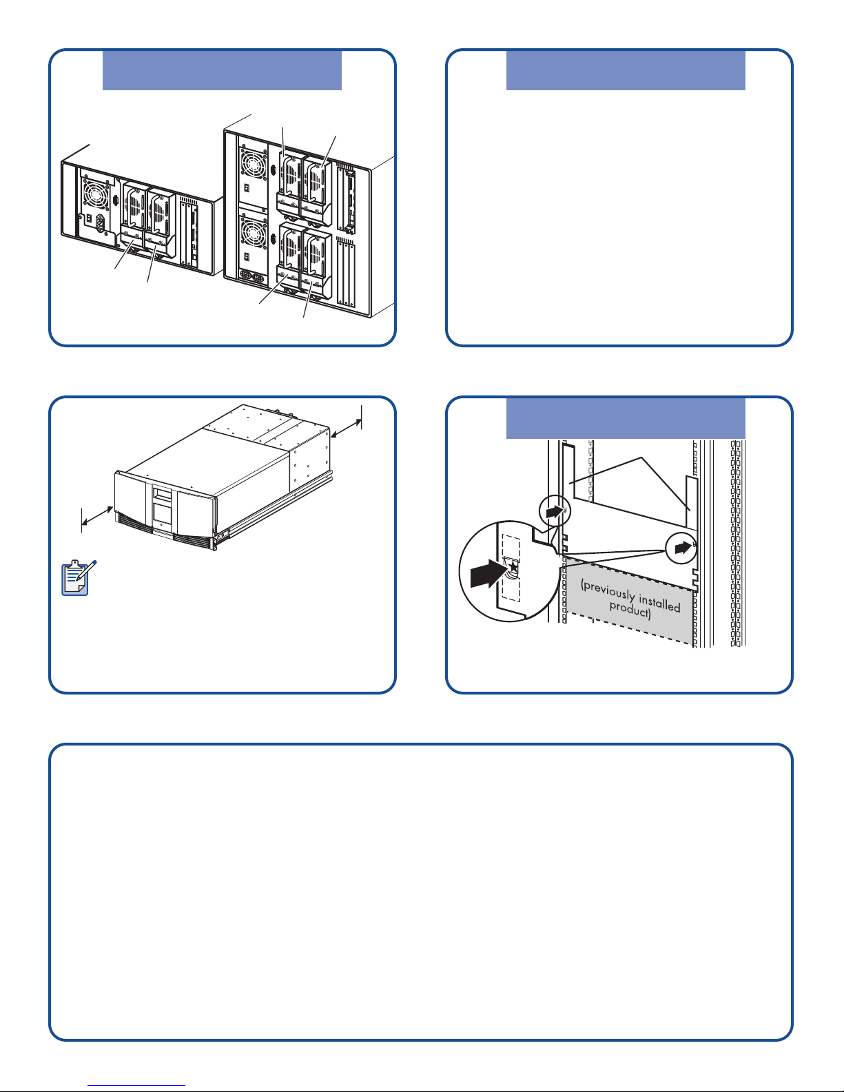
FRONT VIEW:
REAR VIEW:
1. Power supply
2. Power switch
3. Pass-through
mechanism interface
controller
4. Pass-through
mechanism mounting
location
5. Blank cover
6. Tape drive 0
7. Accessory PCI slots (2)
8. Library controller
board
Page 2
Getting Connected
Install the Mounting Rails
Getting Connected
4-drive models
Drive 1
Drive 0
Drive 3
Drive 1
Drive 0
Drive 2
18"
18"
(50 cm)
(50 cm)
12
3
Depending on the model, your library may
look different from the ones illustrated in this
procedure.
Refer to the HP StorageWorks MSL6000 Series
Tape Library User Guide for additional
procedures.
Note: Save the packing materials for use in
moving and shipping the library in the future.
Select a location that is flat, sturdy, and level.
Ensure that the cooling grills at the front and
the fans at the rear are not obstructed. Do not
place the library on its side or stack items on top
of the library.
Use the template shipped
with the library to mark the rack with the
attachment locations of the mounting hardware.
a. Push back the tabs on the top of the template and place them in the holes of the mounting rails. Match up
the hole pattern printed on the sides of the template with the hole pattern in the mounting rails.
b. Make sure to begin measuring in the correct place. If a component is already installed immediately below
the planned position of the new component, place the template against the front mounting rails and rest it
on top of the previously installed component.
c. Use the front of the template to mark the attachment points on the front of the rack enclosure for mounting
brackets, rails, components, or clip nuts.
d. Use the back of the template to mark the attachment points on the back of the rack enclosure for mounting
brackets, rails, components, or cage nuts.
e. Remove the template and attach the rails using the supplied fasteners.
Page 3

Install the Library
into the Rack
Connecting the
SCSI Cables
Note: Rail front brackets are threaded to
directly accept screws. Rear brackets are
not threaded and require installation of
cage nuts in the rack enclosure’s rear
vertical rails. See the documentation
provided with your rack enclosure for
detailed installation instructions.
Caution: Fully tighten the front rail
screws. Leave the rear rail screws finger
tight to prevent binding when installing
the library.
Front of rack
3
Back of rack
1
2
4
f. Fully extend the slide rails 1 on both sides
of the rack enclosure until they lock.
g. Slide the inner bearing race 2 as far as
possible to the front of the rail assembly.
h. Install the two slide-on clip nuts 3 .
5
1
2
3
6
Warning:
Two people
should
perform the
next step.
When the library is fully extended, ensure
that the rack enclosure does not
overbalance.
a. Using two people, lift the library and visually
align the inner and intermediate slide rails.
b. Carefully
insert the library’s
inner slide rails 3
into the extended intermediate slide rails 2 .
c. Slide the library into the rack enclosure until
the rail locks are engaged.
d. Level the rear of the library and fully tighten
the rear rail screws.
Retaining screws
8
e. Remove the tape
securing the library
doors in place.
f. Remove and discard the
pull-tabs used to block
the latch mechanism
when closing the doors.
g. Secure the front panel
to the rack enclosure using the retaining
screws and then close the doors.
Note: Two-drive libraries require four
retaining screws; four-drive libraries
require two retaining screws.
Use the following guidelines when configuring your
SCSI cables:
• Use the highest quality SCSI cables. Bus errors
caused by excessive length or poor quality
cables can significantly degrade performance
and reliability.
• Each tape drive in the library (and the library
controller) is a separate SCSI target. When
more than one device is connected to the same
bus, each separate device must be assigned a
unique SCSI ID.
7
Page 4

To Host
9
• SCSI IDs are set at the factory. Use the GUI touch
screen to change any of the factory defaults.
• To connect a library to a host, the host must have at
least one Wide LVD/SE controller and the appropriate
driver software.
• For best performance, do not attach more than two
drives per bus. A maximum of one tape drive per bus
is recommended for Ultrium 460 and 960 tape drives.
• HP recommends that the robot and drive 0
be attached to host bus 0.
• For Windows servers, power on the library before
powering on the server.
Power On the Library
10
Connect each power cord and turn on the
master power switch for each power supply.
If necessary, turn the library on by touching
the GUI touch screen.
11
12
Note: For
4-drive libraries,
the left power receptacle goes with the
bottom power supply and the right power
receptacle goes with the top power supply.
Getting Help
• HP product information:
ht
tp://www.hp.com/go/storage
• HP technical support and phone numbers:
ht
tp://www.hp.com/support
• HP StorageWorks Library and Tape Tools
(L&TT) diagnostic software:
ht
tp://www.hp.com/support/tapetools
After you install and configure the library,
complete the following setup tasks. Refer to the
HP StorageWorks MSL6000 Series Tape Library
User Guide for more information.
• Set the mailslot (optional). The default is
mailslot enabled.
• Set the SCSI IDs (if needed to avoid conflicts).
• Set the library's IP address for Web access
(optional).
• Change the default passwords (optional).
• Load tapes into the library.
• Configure your application software.
Page 5

Navigating the GUI Menu
MENU
EDIT OPTIONS
UTILITIES
Factory
Security Level
MaintenanceDiagnostics
Clean Drive
Replace Drive
Drive Format
Set User Defaults
Force Reconfiguration
Reboot Library
Flash Drive From Tape
Flash Drive From SCSI
Cartridge Cycle
(service only)
Drive Cycle
(service only)
BarCode Cycle
(service only)
Inventory*
Sensor Test*
Vertical Calibration
(4-drive models only)
View Error Log*
Touch Screen Calibrate*
Tachometer Diagnostic*
Friction Diagnostic*
Library
SCSI
Network
Passwords
* Visible with a service password
VIEW SYSTEM DATA
Library Options
SCSI Options
Network Options
Library Info
Cartridge Map
Page 6

© 2005, 2007 Hewlett-Packard Development Company, L.P.
Third Edition (January 2007)
Part Number: 331707-003
*331707-003*
331707-003
 Loading...