

Page 1
hp surestore
interface manager
user’s guide
Part Number: C9578-90000
Edition 1
December 2001
© 2001 Hewlett-Packard Company
Page 2

Typographical conventions and
In this manual
terms
Bold: Menu choices and screens on the
library.
[Bold]: Soft keys to press on the library.
Computer:
Emphasis: Draws attention to items within
This table format indicates the menus you need to
enter on the library front panel:
Edit -> Create -> SCSI-II Library
Note Notes explain significant concepts or
Caution Cautions call attention to an operating
Host and SCSI commands.
text.
operating instructions.
procedure or practice that could
damage the product if not correctly
performed. Do not proceed until you
understand and meet these required
conditions.
Chapter 1 Introduction: Describes the
operation of the HP Surestore
Interface Manager, as well as
manager components and
supported products.
Chapter 2 Overview: Provides an overview
of the configuration options.
Chapter 3 Management Operations:
Describes the management
operations, system utilities and
statistics, diagnostics and trace
history.
Chapter 4 SAN Environments: Provides an
overview of Storage Area Network
environments.
Chapter 5 Troubleshooting: Describes the
troubleshooting process, as well as
problem-solution scenarios.
Appendix A DB-9 Serial and RJ-45 Ethernet
Pin Assignment
Appendix B Fibre Channel Interface and
Commands
Appendix C SCSI Interface and Commands
Appendix D Customer Support
WARNING Warnings call attention to a procedure
or practice that could result in personal
injury if not correctly performed. Do
not proceed until you fully understand
and meet the required conditions.
2 Typographical conventions and terms hp surestore interface manager
Page 3

Notice
This document contains information that is protected
by copyright. All rights are reserved. No part of this
document may be photocopied, reproduced, or
translated into another language. The information
contained in this document is subject to change
without notice.
Warranty
Note See Appendix D for more
information about service and support.
HP Product: HP Surestore Interface Manager
Duration of limited warranty: One Year
1. HP warrants HP hardware, accessories, and
supplies against defects in materials and
workmanship for the period specified above. If
Hewlett-Packard receives notice of such defects
during the warranty period, Hewlett-Packard will,
at its option, either repair or replace products
which prove to be defective. Replacement products
may be either new or like-new.
2. HP warrants that HP software will not fail to
execute its programming instructions, for the
period specified above, due to defects in material
and workmanship when properly installed and
used. If HP receives notice of such defects during
the warranty period, HP will replace software
media that does not execute its programming
instructions due to such defects.
3. HP does not warrant that the operation of HP
products will be uninterrupted or error free. If HP is
unable, within a reasonable time, to repair or
replace any product to a condition as warranted,
customer will be entitled to a refund of the
purchase price upon prompt return of the product.
4. HP products may contain remanufactured parts
equivalent to new in performance or may have
been subject to incidental use.
5. The warranty period begins on the date of
delivery or on the date of installation if installed by
HP. If customer schedules or delays HP installation
more than 30 days after delivery, warranty begins
on the 31st day from delivery.
6. Warranty does not apply to defects resulting from
(a) improper or inadequate maintenance or
calibration, (b) software, interfacing, parts or
supplies not supplied by HP, (c) unauthorized
modification or misuse, (d) operation outside of
the published environmental specifications for the
products, or (e) improper site preparation or
maintenance.
7. TO THE EXTENT ALLOWED BY LOCAL LAW, THE
ABOVE WARRANTIES ARE EXCLUSIVE AND NO
OTHER WARRANTY OR CONDITION, WHETHER
WRITTEN OR ORAL, IS EXPRESSED OR IMPLIED
AND HP SPECIFICALLY DISCLAIMS ANY IMPLIED
WARRANTIES OR CONDITIONS OF
MERCHANTABILITY, SATISFACTORY QUALITY,
AND FITNESS FOR A PARTICULAR PURPOSE.
8. HP will be liable for damage to tangible property
per incident up to the greater of $300,000 or the
actual amount paid for the product that is the
subject of the claim, and for damages for bodily
injury or death, to the extent that all such
damages are determined by a court of competent
jurisdiction to have been directly caused by a
defective HP product.
9. TO THE EXTENT ALLOWED BY LOCAL LAW, THE
REMEDIES IN THIS WARRANTY STATEMENT ARE
THE CUSTOMER’S SOLE AND EXCLUSIVE
REMEDIES. EXCEPT AS INDICATED ABOVE, IN
NO EVENT WILL HP OR ITS SUPPLIERS BE LIABLE
FOR LOSS OF DATA OR FOR DIRECT, SPECIAL,
INCIDENTAL, CONSEQUENTIAL (INCLUDING
LOST PROFIT OR DATA), OR OTHER DAMAGE,
WHETHER BASED IN CONTRACT, TORT, OR
OTHERWISE.
hp surestore interface manager Notice 3
Page 4

Reference Standards
■ Fibre Channel Physical and Signaling Interface
(FC-PH), ANSI X3T9.3/Project 755D/Rev. 4.3,
Contact: Global Engineering, 1-800-854-7179.
■ Fibre Channel Protocol for SCSI (FCP) Rev. 12
■ Fibre Channel Private Loop Direct Attach (FC-
PLDA).
■ Fibre Channel Arbitrated Loop (FC-AL), ANSI
X3T11/Project 960D/ Rev. 4.54, Contact: Global
Engineering, 1-800-854-7179.
■ Gigabit Interface Converter (GBIC), Small for
Factor, SFF-8053, Rev. 5.X.
■ Common FC-PH Feature Sets Profiles, Fibre
Channel Systems Initiative, FCSI-101-Rev. 3.1.
■ SCSI Profile, Fibre Channel System Initiatives,
FCSI-201-Rev. 2.2.
■ FCSI IP Profile, Fibre Channel System Initiative,
FCSI-202-Rev. 2.1.
■ ANSI Document T10/99-143 r1 www.t10.org.
4 Reference Standards hp surestore interface manager
Page 5

Typographical conventions and terms 2
In this manual 2
Notice 3
Warranty 3
Reference Standards 4
Chapter 1 Introduction 11
Chapter Overview 11
How the Interface Manager (IM) Works 12
Processing SCSI Information 14
Interface Manager (IM) Features 15
Fibre Channel Features 15
SCSI Bus Features 15
Configuration Features 15
Management Features 16
Interface Manager (IM) Components 17
Supplied Components for the Interface Manager 17
Specifications 19
Physical Specifications of the Interface Manager (IM) 19
Environmental Specifications 19
Supported Products 20
Optical Fibre Channel Cables 22
contents
5
Page 6

Chapter 2 Interface Manager Overview 23
Chapter Overview 23
Overview of the Interface Manager (IM) Configuration 24
Choosing the Right Configuration 25
Fibre Channel Port Mode 28
Fibre Channel Arbitrated Loop Addressing 29
Hard Addressing 29
Soft Addressing 29
Host Device Configuration 30
SCSI Addressing 30
Buffered Tape Writes 30
Address Mapping 31
Auto-Indexed Mapping 32
Fixed-Indexed Mapping 32
Configuration Methods 33
Serial 33
Ethernet 33
Telnet 33
Web Based Administrator 34
Chapter 3 Management Operations 35
Chapter Overview 35
Management Interfaces 36
Serial 36
Ethernet 36
Telnet 36
Web Based Administrator 37
FTP 37
Configuration Using the Telnet Interface 38
Overview 38
Accessing Telnet 38
Changing the Administration Password Using Telnet 40
Changing the Clock Setting Using Telnet 40
Changing the Ethernet Configuration Using Telnet 42
Changing the Fibre Channel Address Modes Using Telnet 42
Hard Addressing 43
Soft Addressing 44
Using Your Own Settings 44
Placing a Fibre Channel Interface Card Off-Line Using Telnet 45
Placing a Fibre Channel Interface Card On-Line Using Telnet 47
6
Page 7

Installing a New Fibre Channel Interface Card Using Telnet 49
Changing a Fibre Channel Interface Card Configuration Using Telnet 51
Choosing Which Card to be Configured 51
Factory Defaults for the Fibre Channel Interface Card 52
Configuration Using the Web Based Administrator 53
Overview 53
Accessing the Web Based Administrator 55
Making Changes via the Web Interface 56
Changing the Clock Setting Using the Web Administrator 56
Setting Date and Time 56
Time Shown is NOT Correct 57
Setting a Time That is Different From the Time Shown 58
Changing the Ethernet Configuration Using the Web Administrator 58
Using DHCP 59
Not Using DHCP 60
Changing the FC Address Modes Using the Web Administrator 60
Hard Address Settings 62
Soft Address Settings 62
Selecting Your Own Settings 63
Placing a FC Interface Card Off-Line Using the Web Administrator 64
Placing a FC Interface Card On-Line Using the Web Administrator 67
Installing a New Interface Card Using the Web Administrator 70
Download a New Revision of the Firmware 72
Using the Web Interface 72
FTP Interface (All Cards)- Customer Engineer (CE) Only 74
Upgrade Firmware Using FTP 74
FTP Interface (Single Card) 75
Upgrade Firmware Using FTP 75
7
Page 8

Chapter 4 SAN Environments 77
Chapter Overview 77
Installation and Configuration 78
Omniback Configuration 81
HP-UX Configuration 85
Stopping the dm_stape process 88
Preventing dm_stape from polling 91
Windows Configuration 92
Windows 2000 Removable Storage Manager 92
Solaris Configuration 94
Switch Configuration 95
HP/Brocade Switch and Interface Manager Configuration 95
FC-64 Director (McData) Switch 96
Troubleshooting 97
Chapter Overview 97
Troubleshooting 98
Operation Indicators 99
Basic Verification 103
LED Indicators 103
Verify SCSI Bus Configuration 103
Verify Fibre Channel Connection 104
Verify SCSI Devices in Windows NT 104
Verify Device Recognition in HP-UX 105
Verify Configuration 106
Verify Devices 106
Verify Host Configuration 106
Verify HBA Device Driver Information 106
Serial Port Problems 106
Customer Support 106
Problem - Solution 107
Problem: Drives Not Detected after Power Failure 107
Option 1 - Not Using Telnet or the Web Interface 107
Option 2 - Using Telnet 107
Option 3 - Using the Web Interface 107
Problem: Cannot Turn on the Interface Manager 108
Problem: Cannot Confirm the Library Connection (Windows NT) 108
Problem: Cannot Confirm Connection Through a Fibre Channel Switch 110
Problem: Cannot Confirm the Library Connection (HP-UX) 110
8
Page 9

Appendix A DB-9 Serial and RJ-45 Ethernet Pin Assignment 115
Serial and Ethernet Assignment 115
Appendix B Fibre Channel Interface and Commands 117
Download Commands 117
Upgrade Firmware 117
Report LUNs Command 119
PRLI Data 121
Appendix C SCSI Interface and Commands 123
SCSI Inquiry Data 123
Appendix D Customer Support 125
Registering Your Product 125
Backup Software Support 125
Hewlett-Packard Customer Support 126
Information Needed for Support 126
9
Page 10

10
Page 11

Introduction
Chapter Overview
This chapter contains information on the following:
■ How the Interface Manager (IM) Works on page 12
■ Processing SCSI Information on page 14
■ Interface Manager (IM) Features on page 15
■ Interface Manager (IM) Components on page 17
■ Specifications on page 19
■ Supported Products on page 20
1
Introduction 11
Page 12

How the Interface Manager (IM) Works
The IM provides connectivity between a Fibre Channel (FC) switched fabric
(FC-SW) or Fibre Channel arbitrated loop (FC-AL) and up to 20 Ultra-2 SCSI
buses.
The IM contains slots for up to eleven (one slot is reserved for future expansion)
Fibre Channel cards. Each card connects a FC port to two Ultra-2 SCSI ports.
The IM also contains a Remote Management Card (RMC) in slot 1, and a
controller card in slot 2. The RMC provides the user with a serial port for initial
setup, as well as Telnet and Web Administrator - HTTP access to any of the
cards in the IM.
Each FC card translates the FC protocol (FCP) to and from the SCSI protocol so
that FC and SCSI devices can communicate. The FC card attaches to a FC host,
hub, or switch and transfers the command, data, and status information to
SCSI targets. Packets are transferred transparently by the IM between a host
and targets and vice versa.
SCSI and Fibre Channel connectors are accessed from the front of the IM.
Ethernet and serial ports provide the means for configuring and managing the
IM. A power connector is located on the front of the Interface Manager.
12 Introduction Chapter 1
Page 13
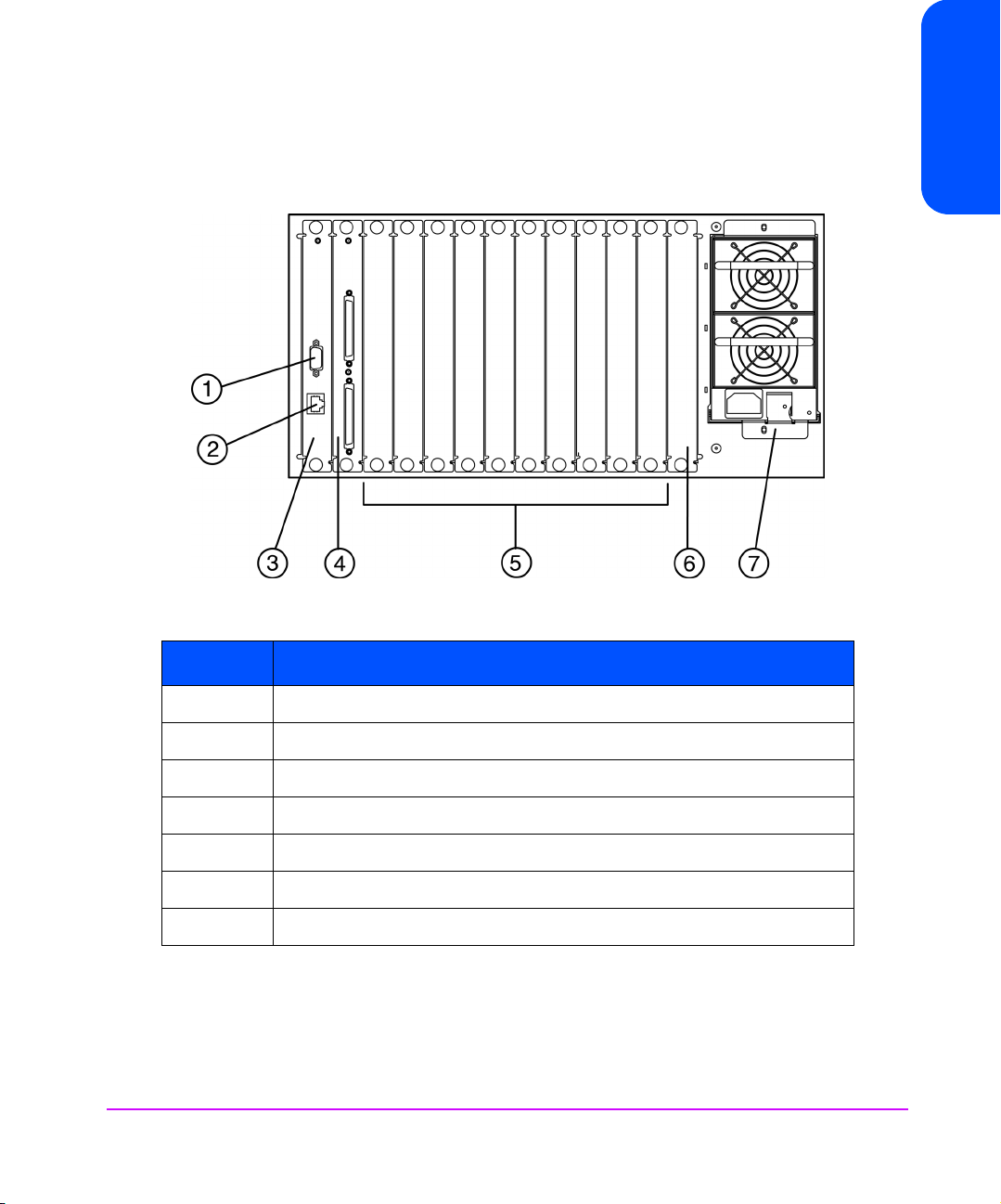
Figure 1 shows the front view of the Interface Manager.
Figure 1 Front View of the Interface Manager
Chapter 1
Table 1 Features of the Interface Manager
Number Part
1 Serial DB-9 connector for terminal access
2 Ethernet RJ-45 connector for FTP, Telnet and Web browser access
3 Remote management card
4 Controller card
5 Slots for Fibre Channel interface cards
6 Reserved slot
7Redundant power supply
Chapter 1 Introduction 13
Page 14

Processing SCSI Information
The following section describes how the Interface Manager (IM) processes SCSI
information when attached to Fibre Channel (FC) hosts.
1. A FC host issues a command. The FC host encapsulates the SCSI
command in the FC protocol and sends the packet to the IM.
2. The FC card in the IM receives the packet, interprets the FC information,
and places the packet in buffer memory.
3. The IM’s processor interprets the information and programs a SCSI
controller to process the transaction.
4. The SCSI controller sends the command to the SCSI device (target).
5. The SCSI target interprets the command and executes it.
6. Data flows between the FC host and SCSI target through payload buffers.
7. Response information flows from the SCSI target back to the FC host.
14 Introduction Chapter 1
Page 15

Interface Manager (IM) Features
Fibre Channel Features
■ Fibre Channel target mode
■ Single 1.0625 Gbps FC port
■ Fibre Channel arbitrated loop (FC-AL) and switched fabric (FC-SW)
topologies, includes point-to-point (PPP) configurations
■ Private Loop Direct Attach (PLDA) profile compliant
■ Class 3 connection with SCSI-FCP protocol
■ Supports FCP-2 error recovery protocol as specified in FCP-2 rev. 03 for
use with streaming devices (such as tape) and medium changers
SCSI Bus Features
■ SCSI initiator mode
■ Up to 20 auto-negotiating SCSI buses (Narrow, Wide, Fast, Ultra)
■ Ultra-2 wide SCSI for data transfer up to 80MB/s per bus (LVD)
■ Ultra-2 wide SCSI for data transfer up to 40MB/s per bus (HVD)
Chapter 1
■ SCSI-2 and SCSI-3 protocols
■ Differential or LVD/single-ended internal termination
(HVD or LVD Single-ended)
■ Supports tape and medium changer SCSI devices
Configuration Features
■ DHCP for easier network administration
■ Serial DB-9 connector for terminal access
■ Ethernet RJ-45 connector for FTP, Telnet and Web browser access
■ Field-upgradeable firmware
Chapter 1 Introduction 15
Page 16

Management Features
■ Out-of-band Ethernet TCP/IP management access
■ In-Band management
16 Introduction Chapter 1
Page 17
Interface Manager (IM) Components
This section includes a list of all parts supplied with the IM, and environmental
considerations.
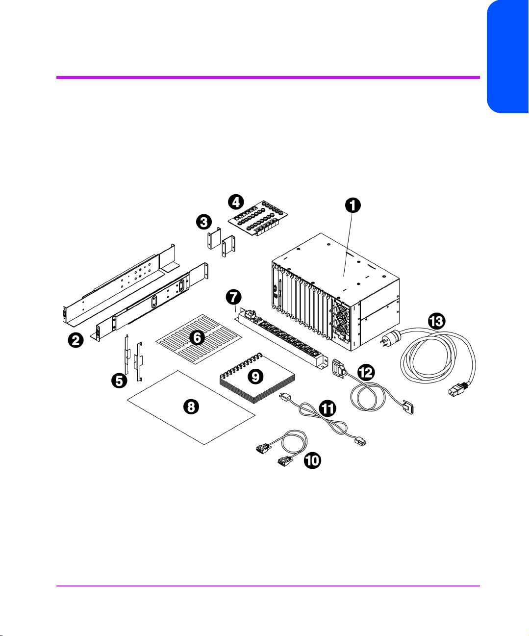
Supplied Components for the Interface Manager
Figure 2 Supplied Components
Chapter 1
Chapter 1 Introduction 17
Page 18

Table 2 Supplied Components
No. Item Qty Description
1 HP Surestore Interface Manager 1 Base Product: Chassis, Interface Manager controller,
remote management card, power supply and three fans
2 Mounting rails 2 Left and right mounting rails
3 Mounting rail extensions 2 Used for the 10/180 tape library only
4 Hardware identification board 1 Hardware consisting of:
6 - 10x32 hex nuts
12 - sheet metal nuts
16 - 10x32 x 50 machine screws
5 Flush mount brackets 2 Left and right flush mount brackets
6 Cable labeling kit 1 Label kit to label the SCSI and fibre cables
7 Power distribution unit 1 Power distribution unit
8 HP Surestore Interface Manager
Installation and Cabling Poster
9 HP Surestore Interface Manager
User’s Guide
10 Serial cable 1 Serial cable
11 Power cord 1 power cord (PDU to the Interface Manager)
12 SCSI cable 1 2.5 meter FC SCSI cable for daisy chaining the robotics to
13 Localized power cord 1 Localized power cord (wall to PDU)
18 Introduction Chapter 1
1 Installation and Cabling Poster
1User’s Guide
a drive - High Density - Do not use with the Interface
Manager
Page 19

Specifications
Physical Specifications of the Interface Manager (IM)
The IM is installed inside the accessory bin of the 10/180 and 20/700 HP
tape libraries.
The physical characteristics are as follows:
Table 3 Physical Specifications of the Interface Manager
Height 8.48 inches (21.2 cm)
Width 17.26 inches (43.15 cm)
Depth 10.78 inches (26.95 cm)
Chapter 1
Weight (to include box with fans,
redundant power supply, Interface
Manager controller and RMC boards and
11 slot covers)
Environmental Specifications
Choose a location that meets the following criteria:
Table 4 Location Criteria
Room temperature 50
Humidity 20% to 80% relative humidity, non-condensing
Power source AC power voltage: 100-127 VAC/200-240VAC
Approximately 34.2 pounds
(15.54 kg)
o
- 95o Farenheit (10o - 35o C)
50-60 Hz
Chapter 1 Introduction 19
Page 20

Supported Products
Table 5 shows the products that Hewlett-Packard supports for connection with
the Interface Manager:
Table 5 Supported Products
Description Product
HP SureStore E Tape Libraries:
10/180 and 20/700 with Ultrium,
DLT 7000, DLT 8000, and 9840 tape
drives
HP Fibre Channel Switches Brocade SilkWorm 2800 - A5624A
QLogic Fibre Channel HBA Win NT 4.0, Windows 2000, Netware 5.x - QLA-2200F
Emulex HBA Win NT 4.0, Windows 2000 - LP8000-N1, LP8000-F1
Compaq HBA Win NT 4.0, Windows 2000 - 176479-B21
10/180 - A5617A
20/700 - A5597A, A5597B
Brocade SilkWorm 2400 - A5625A
20 Introduction Chapter 1
Page 21

Table 5 Supported Products
Description Product
HP Fibre Channel Host Bus Adapters HP-UX 11.11,11.0 A5158A (pci)
HP-UX 11.11,11.0, 10.20 A6685A (hsc-K class), A6684A
(hsc-D, R class)
A6684A and A6685A adapters are only supported on the
following R, D, and K-class servers:
A6684A Supported Platforms:
R-class R380.R390
D-class D220.D230/D320/D330
D270/D280/D370/D380/D390
A6685A Supported Platforms:
K-class K220/K420/K250/K450/K260/K360/
K370/K380/K460/K570/K580
HP-UX 11.0; V, N & L Class - A5158A
HP-UX 10.20 & 11.0; T600 - A3636A
HP-UX 10.20 & 11.0; D & R Class - A3591B
HP-UX 10.20 & 11.0; K Class - A3404A
Win NT 4.0, Windows 2000 - D8602A
Win NT 4.0 SP 4 & above; HP Netserver - D8602A/B
Win NT 4.0 SP 4 & above; Compaq Proliant - D8602A/B
Win NT 4.0 SP 4 & above; Dell PowerEdge - D8602A/B
Win NT 4.0 SP 4 & above; IBM Netfinity - D8602A/B
Chapter 1
Sun Solaris 2.6, 7, 8 JNI FC64-1063N (sbus)
JNI FCI-1063 (pci)
JNI FCE-1063-N (sbus)
FCE-6410-N (pci)
Note DLT 7000 tape drives are only supported in the 20/700 tape
library.
Chapter 1 Introduction 21
Page 22

Note The A3636A, A3591B and the A3404A FC HBA are only
supported in point-to-point (PPP) configurations (not through a
switch).
Note HVD SCSI tape drives (DLT 7000, DLT 8000, 9840, and the
HVD version of Ultrium) should only be attached to HVD SCSI
ports on the Interface Manager.
Optical Fibre Channel Cables
The Interface Manager uses the following fiber-optic cables available in the
lengths listed in Table 6.
Table 6 Fibre-Optic Cable Lengths
Product Number Length
A3583A FC Optical Cable 2 meters
A3531A FC Optical Cable 16 meters
A3735A FC Optical Cable 50 meters
A3736A FC Optical Cable 100 meters
A5225A SW Optical/GBIC N/A
22 Introduction Chapter 1
Page 23

Interface Manager Overview
Chapter Overview
This chapter contains information on the following:
■ Overview of the Interface Manager (IM) Configuration on page 24
■ Choosing the Right Configuration on page 25
2
Chapter Overview 23
Page 24

Overview of the Interface Manager (IM) Configuration
The IM can be configured through one of several user interfaces:
■ Over a serial port via a terminal or terminal emulation utility
■ Over Ethernet via a Telnet utility, Internet Web browser, or SNMP
management tool
Note Before configuring the Interface Manager, a basic understanding
of Fibre Channel and SCSI devices is recommended.
For information on SCSI standards, refer to publications from the
X3T10 committee of ANSI (American National Standards
Institute). For information on Fibre Channel standards, refer to
publications from the X3T11 committee of ANSI. Approved
American National Standards and Technical Reports may be
purchased from:
ANSI
11 West 42nd Street
13th Floor
New York, NY 10036
Sales Department: (212) 642-4900
24 Overview of the Interface Manager (IM) Configuration Chapter 2
Page 25

Choosing the Right Configuration
The factory default settings of the Interface Manager (IM) permit the type of
configuration shown in Figure 3 on page 26 (standard configuration) to work
without any initial changes to these settings. The IM settings may need to be
changed for expanded configurations (see Figure 4 on page 27) or certain
application requirements.
Chapter 2
Chapter 2 Choosing the Right Configuration 25
Page 26
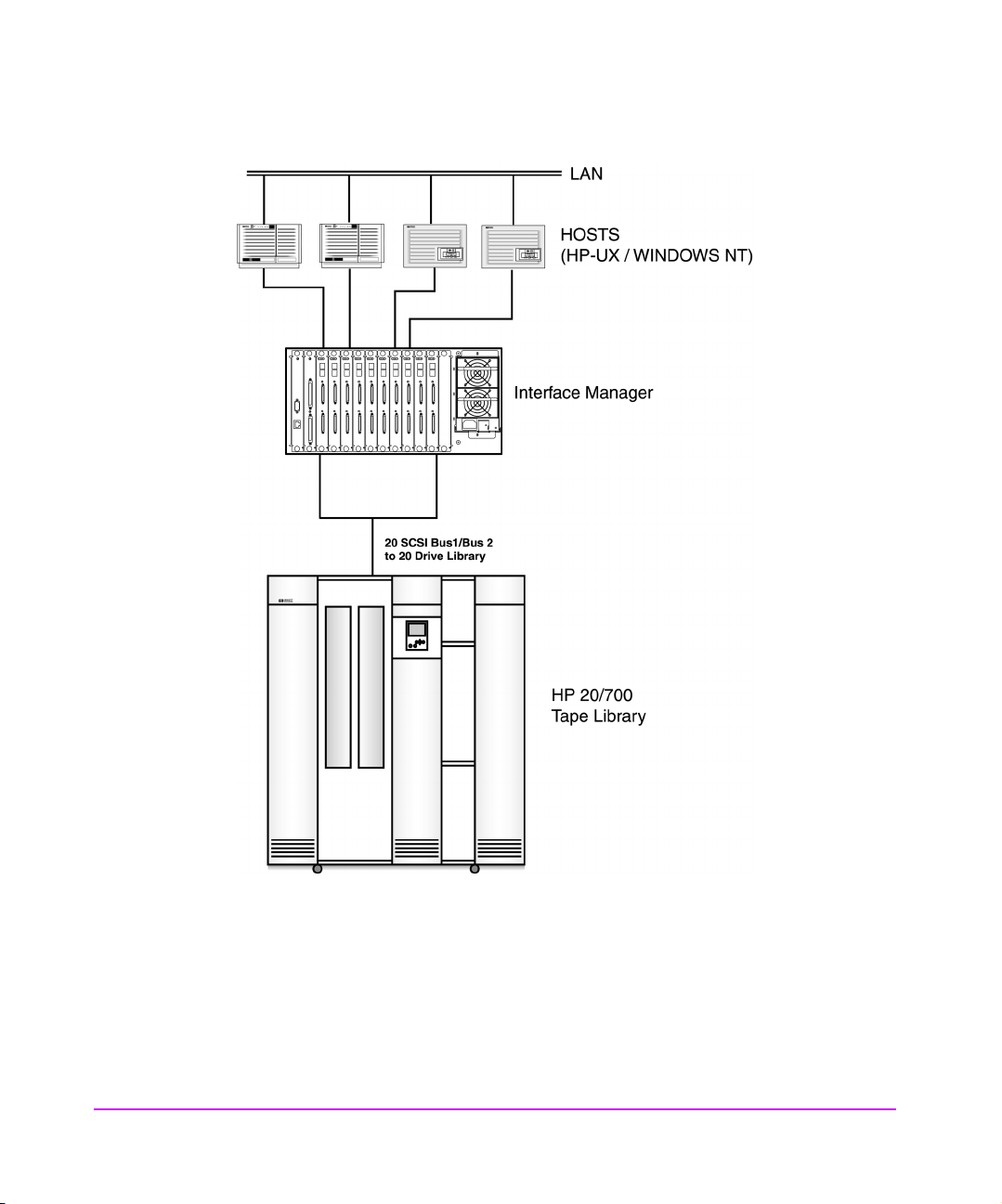
Figure 3 Example of a Standard Configuration in a 20/700 Tape Library
26 Choosing the Right Configuration Chapter 2
Page 27
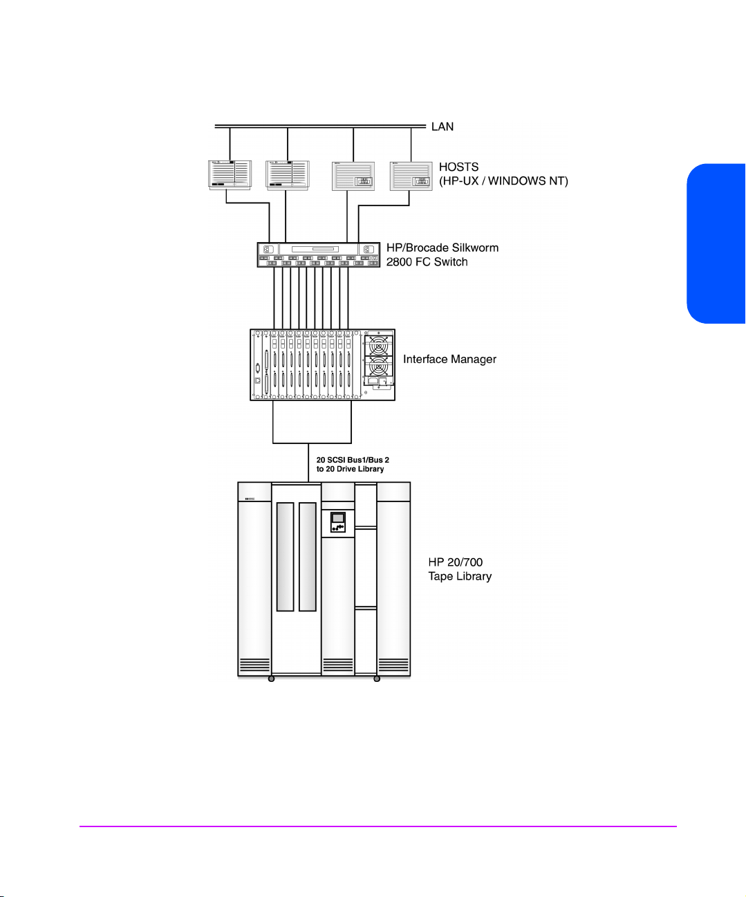
Figure 4 Expanded Configuration
Chapter 2
Chapter 2 Choosing the Right Configuration 27
Page 28

A standard configuration may involve several Fibre Channel (FC) hosts
connected to multiple FC cards. These FC host systems may be connected to
the cards either in a point-to-point (PPP) fashion or through a FC switch. Each
card is then connected to two SCSI tape drives.
The library’s robotics controller may be daisy-chained with one of the SCSI
tape drives or connected directly to an available FC interface card SCSI port,
or direct connect SCSI to host.
Note When daisy-chaining the library’s robotics controller to any LVD
Fibre Channel Port Mode
The IM’s Fibre Channel ports can operate in either NL_Port or N_Port mode.
The IM has the ability to autosense and choose between these modes of
operation.
■ NL_Port - The IM can share a FC Arbitrated Loop with other NL_Port
devices (or HBAs). A single FC switch port acting in FL_Port mode can
also be connected to the loop.
■ N_Port - The IM does not employ the arbitrated loop protocol. This allows
for a more efficient connection to a single FC switch port acting in F_Port
mode.
Some FC switches (such as the HP/Brocade SilkWorm) support either FL_Port
and F_Port modes with autosensing capabilities. Other switches (such as the
HP Surestore Director) only support the F_Port mode. When connecting directly
to a FC switch port, configure the IM in N_Port mode for a more stable and
efficient connection.
Port mode can only be set in the FC Configuration menu via the Telnet
interface. See Configuration Using the Telnet Interface on page 38.
tape drive, the library must have the LVD to HVD converter
(A6324A) installed.
28 Choosing the Right Configuration Chapter 2
Page 29

Fibre Channel Arbitrated Loop Addressing
On a FC arbitrated loop, each device appears as an Arbitrated Loop Physical
Address (AL_PA). To obtain an AL_PA, two methods called soft and hard
addressing can be used by the IM. The IM can be configured to use either
method.
Hard Addressing
Hard addressing is recommended for FC arbitrated loop environments where it
is important that the FC device addresses do not change. Device address
changes can affect the mapping represented by the host operating system to
the application. An example of such an environment would be a tape library
installation, where the application configuration requires fixed device
identification for proper operation. Hard addressing ensures that the device
identification to the application remains constant.
When acquiring a hard address, the IM attempts to acquire the AL_PA value
that was specified by user configuration. If the desired address is not available
at loop initialization time, the IM will come up on the FC loop using an
available soft address. This allows the loop to continue to operate. This
situation would occur when another device on the arbitrated loop has
acquired the same address as that configured on the IM.
When connected to a FC switch, the IM is identified to the switch as a unique
device by the factory programmed World Wide Name (WWN).
Soft Addressing
Soft addressing is recommended for FC fabric environments where the FC
interface card does not employ the Arbitrated Loop protocol. In these
environments, an AL_PA is not used as part of the device address, so soft
addressing allows the FC interface card to operate as an N_Port. Soft
addressing is recommended primarily for switched fabric configurations.
When acquiring a soft address, the FC interface card acquires the first
available loop address starting from address 01 and moving up the list of
available AL_PAs to EF. In this mode, the FC interface card automatically
obtains an available address and participates on the FC loop, as long as there
is at least one address available on the loop that is connected to the IM. FC
supports up to 126 devices on an arbitrated loop.
Chapter 2
Chapter 2 Choosing the Right Configuration 29
Page 30

Host Device Configuration
The host system using a FC host bus adapter (HBA) will typically map FC
devices into the existing device mapping scheme used by that operating
system. (Refer to your HBA manual for the mapping table.) The FC usually
maps FC addresses to SCSI target addresses. In such a configuration, the IM
corresponds to a bus:target identifier, with the SCSI devices attached to the IM
appearing as logical units (LUNs). In addition, operating systems can extend
the available SCSI limit of 15 Target IDs per bus.
Although this is not an issue for the operating system or most applications,
there are cases where older applications or Windows NT can have
expectations about what are valid SCSI IDs, and not deal correctly with certain
mappings. In particular, applications have been seen to exhibit difficulties
addressing Target IDs greater than 15 (e.g. 16 and up). This problem can be
resolved by configuring the IM to use hard addressing, and setting the AL_PA
used by the IM to a value that the HBA will map to, with an ID having a value
less than 16.
SCSI Addressing
A FC interface card appears on each SCSI bus as a single initiator. The default
initiator ID is 7. No other device on the SCSI bus may use this address. Note
that the FC host itself is not connected to the bus. Their SCSI operations are
passed down to the individual SCSI target devices through the use of the IM’s
SCSI Initiator ID.
The IM negotiates for the maximum values for transfer rates and bandwidth on
a SCSI bus. If an attached SCSI device does not allow the full rates, the IM will
use the best rates it can negotiate for that device. Negotiation is on a device
specific basis, so the IM can support a mix of SCSI device types on the same
SCSI bus.
Buffered Tape Writes
Buffered Tape Writes is an option designed to enhance system performance.
By returning status on consecutive write commands prior to the tape device
receiving data, Buffered Tape Writes remove the latency of waiting for
responses from the tape device. In the event that data does not transfer
correctly for any reason, the interface card will return a check condition on a
subsequent command.
30 Choosing the Right Configuration Chapter 2
Page 31

Address Mapping
Commands other than Write are not issued until status is received for any
pending Write. Also, status is not returned until the device completes the
command. For instance, when a synchronizing command is sent to the drive,
such as sending a Write File mark, a good status means all prior commands
have been successfully completed and data has been successfully written to the
medium. This is appropriate for such tasks as file backup/restore.
Chapter 2
Note If the application requires confirmation of individual blocks
being written to the medium, such as audit trail tapes or log
tapes, this option should be disabled via the Telnet interface.
SCSI targets are selected by mapping the appropriate values into the FCP LUN
field, and correlating a FC LUN value to a SCSI bus:target:LUN value. The FC
interface card acts as a single initiator on each SCSI bus, fixed at ID 7. All
commands passed through to a SCSI bus originate from this SCSI ID.
FC to SCSI Address Mapping can be independently set for each fibre interface
card in the IM.
Two variations of Indexed Addressing are possible when mapping SCSI targets
to FC initiators (hosts).
By default, the mapping table on each interface is created every time the IM is
power cycled or the individual interface is rebooted. This method is autoindexed.
If auto-indexed mode is disabled, then the mapping table already stored in the
IM’s memory will be used. This method is fixed-indexed.
Chapter 2 Choosing the Right Configuration 31
Page 32

Auto-Indexed Mapping
This is the default method of operation. Discovery of SCSI devices is performed
at every startup (power up, or reboot). As devices are discovered, they are
added to the FC-to-SCSI mapping table. The FC LUN numbers are assigned
sequentially. The mapping table is stored in FLASH memory. An example of a
FC-to-SCSI map for three SCSI devices is shown in Table 1.
Table 1
Fibre Channel SCSI
FCP LUN Bus Target LUN
0 000
1 010
2 120
In this method, the host system detects every attached device without voids in
the FCP LUN list, allowing full device discovery to the host. This allows easy
configuration in environments where device ordering is not important, and hot
plugging of SCSI devices will not occur.
Example of a Fibre Channel-to-SCSI Mapping
Fixed-Indexed Mapping
This is an optional method of operation. Although the interface performs
discovery of SCSI devices at startup, the results of this discovery are not utilized
to create the FC-to-SCSI mapping table. Instead, the copy of the mapping table
stored in FLASH memory is used.
Fixed-indexed is recommended for environments where SCSI device
configurations may change, and a fixed mapping from the application to the
target device is required. That is, if a SCSI device is removed from the SCSI
bus, and the fibre interface is power cycled or rebooted, then the FC-to-SCSI
addressing for the remaining SCSI devices will not change. The SCSI device
can be replaced at the same address. An example of such an environment is
where hot pluggable devices may be used.
32 Choosing the Right Configuration Chapter 2
Page 33

Configuration Methods
The IM can be configured over the serial port via a terminal, terminal
emulation utility or over Ethernet via a Telnet utility, Internet Web browser, or
SNMP management tool. FTP is also supported on Ethernet to upgrade
firmware revisions.
Serial
The serial port allows for configuration of device characteristics from an
attached terminal or terminal emulator. For instructions on use of the serial
interface, see Setting up Serial Port Communications in the HP Surestore
Interface Manager Installation and Service Guide.
Ethernet
The 10/100 BaseT Ethernet port must first be configured via the serial port
prior to use with either DHCP, or appropriate IP address, subnet mask, and
gateway.
Telnet
The IM is capable of holding Telnet sessions for configuration purposes. To
open a Telnet session, the IP address of the IM and a Telnet client utility are
required. The Telnet command may be used from any open window on a HPUX system or from the command prompt on most Windows NT systems. Start a
Telnet session using the following steps:
1. On HP-UX‘, open a terminal window. On Windows NT, open a command prompt window.
2. At the ‘>’ prompt, enter the following command:
TELNET <IP address> where <IP address> is the IP address of the
IM. This will start a Telnet session for the IM. On Windows NT, a separate
Telnet session window will appear.
3. Enter [admin] for the default user name and press [enter] for the default
password. It is recommended that you change the password as soon as
possible. See Changing the Administration Password Using Telnet on
page 40 for more information.
4. Access configuration options via the menu system.
Chapter 2
5. To exit the Telnet session on HP-UX, simply close the window. On
Windows NT, you may select the disconnect option from your Telnet client
utility. In most Telnet utilities, this option is available as a menu item.
Chapter 2 Choosing the Right Configuration 33
Page 34

Web Based Administrator
The IM allows any standard Internet Web browser to view and change the IM
configuration. Information is dynamically generated in an HTML format by the
IM so that Web browsers can access it.
To access the Web interface, enter the IP address of the IM into the address
field of a Web browser. Or, you can enter a URL using a host name defined by
the user.
To make changes to settings, use standard keyboard and mouse controls to
input information and then select the [Apply] button to send the changes to
the IM.
A password is required before any changes can be submitted. It is
recommended that you change the password using the serial or Telnet session
as soon as possible. See Changing the Administration Password Using Telnet
on page 40 for more information on setting up passwords.
34 Choosing the Right Configuration Chapter 2
Page 35

Management Operations
Chapter Overview
This chapter contains information on the following:
■ Management Interfaces on page 36
■ Configuration Using the Telnet Interface on page 38
■ Configuration Using the Web Based Administrator on page 53
■ Download a New Revision of the Firmware on page 72
■ FTP Interface (All Cards)- Customer Engineer (CE) Only on page 74
3
Management Operations 35
Page 36

Management Interfaces
The IM can be managed through several user interfaces:
■ Over the serial port via a terminal or terminal emulation utility
■ Over Ethernet via a Telnet utility, Internet Web browser. Further, FTP
support provides additional management functionality.
Serial
The serial port allows for configuration of the Interface Manager from an
attached terminal or terminal emulator. It is used primarily for initial
configuration at the time of installation.
Ethernet
All management of the interface cards is performed using the Ethernet port.
The 10/100 Base T Ethernet port must first be configured via the serial port
with an appropriate IP address, subnet mask, and gateway prior to use.
Telnet
The IM is capable of holding Telnet sessions for management purposes. To
open a Telnet session, the IP address of the IM and a Telnet client utility are
required. See Accessing Telnet on page 38.
36 Management Operations Chapter 3
Page 37

Web Based Administrator
The IM allows any standard Internet Web browser to view and change the IM
configuration. Information is dynamically generated in an HTML format by the
IM so that Web browsers can access it. Accessing the Web Based
Administrator on page 55.
FTP
The ftp interface is used to download new firmware revisions to the Interface
Manager. See Download a New Revision of the Firmware on page 72.
Chapter 3
Chapter 3 Management Operations 37
Page 38

Configuration Using the Telnet Interface
Overview
■ Accessing Telnet on page 38
■ Changing the Administration Password Using Telnet on page 40
■ Changing the Clock Setting Using Telnet on page 40
■ Changing the Ethernet Configuration Using Telnet on page 42
■ Changing the Fibre Channel Address Modes Using Telnet on page 42
■ Placing a Fibre Channel Interface Card Off-Line Using Telnet on page 45
■ Placing a Fibre Channel Interface Card On-Line Using Telnet on page 47
■ Installing a New Fibre Channel Interface Card Using Telnet on page 49
■ Changing a Fibre Channel Interface Card Configuration Using Telnet on
page 51
■ Choosing Which Card to be Configured on page 51
■ Factory Defaults for the Fibre Channel Interface Card on page 52
Accessing Telnet
To access Telnet, do the following:
1. Apply power to the connected SCSI and Fibre Channel devices
2. After all of the devices have gone through their power-up routines, boot up the IM.
3. Power on the host computer.
From most Windows 9x and NT systems, users can start a Telnet session from
the DOS (or Command) prompt using the following steps:
1. From the Windows Start menu, open the DOS (or Command) prompt window.
2. At the ‘>’ prompt, enter the following command:
Telnet <IP address>
where <IP address> is the IP address of the IM. This will start a Telnet
session window for the IM.
38 Management Operations Chapter 3
Page 39

3. Enter [Admin] for the default user name and select [Enter] for the default
password. It is recommended that you change the password as soon as
possible.
4. Access menu options as needed.
5. If you intend to use the Web interface, do not exit, and see Changing the
Administration Password Using Telnet on page 40 (next section).
Otherwise, to exit the Telnet session, select the [Disconnect] option from
your Telnet client utility. In most Telnet utilities, this option is available as a
menu item, or select the [Log out] choice on the Main menu.
Chapter 3
Chapter 3 Management Operations 39
Page 40

Changing the Administration Password Using Telnet
If you intend to use the Web interface, then you must have a valid password
entered into the IM. To change the administration password:
Log into the IM via a Telnet session as described above in “Acc e s si ng Telne t.”
1. Select [1] from the Main menu.
2. Select [1] from the Administration menu and type in the desired password.
3. The password must contain exactly eight characters, using 1, 2, 3, and 4
only. If you do not want to have a password, then select [Enter].
Changing the Clock Setting Using Telnet
The clock is used to time stamp events in event and error logs. To change the
clock setting:
1. Log into the IM via a Telnet session as described in Accessing Telnet on
page 38.
2. Select [1] from the Main menu.
3. Select [2] from the Administration menu, then answer the questions about today’s date.
4. Select [3] from the Administration menu, then answer the questions about the current time.
The hour is given in military time, where the possible choices range from 0
through 23 hours after midnight. There is no option for handling daylight
savings time. Set your time zone as shown in the following table:
40 Management Operations Chapter 3
Page 41

Table 7 Time Zones
UTC -12 Eniwetok, Kwajalein
UTC -11 Midway Island, Samoa
UTC -10 Hawaii
UTC -9 Alaska
UTC -8 Pacific Time (US and Canada), Tijuana
UTC -7 Mountain Time (US and Canada), Arizona
UTC -6 Central Time (US and Canada), Saskatchewan, Mexico City, Tegucigalpa
UTC -5 Eastern Time (US and Canada), Bogota, Lima
UTC -4 Atlantic Time (Canada), Caracas, La Paz
UTC -3 Brasilia, Buenos Aires, Georgetown
UTC -2 Mid-Atlantic
UTC -1 Atlantic Ocean
UTC Great Britain, Lisbon, Monrovia, Casablanca
UTC +1 Berlin, Stockholm, Rome, Bern, Brussels, Vienna, Paris, Madrid, Amsterdam, Prague,
Warsaw, Budapest
UTC +2 Athens, Helsinki, Istanbul, Cairo, Eastern Europe, Harare, Pretoria, Israel
UTC +3 Baghdad, Kuwait, Nairobi, Riyadh, Moscow, St. Petersburg, Kazan,Volgograd
UTC +3.5 Tehran
UTC +4 Abu Dhabi, Muscat, Tbilisi
UTC +4.5 Kabul
UTC +5 Islamabad, Karachi, Ekaterinburg, Tashkent
UTC +5.5 Bombay, Calcutta, Madras, New Delhi, Colombo
UTC +6 Almaty, Dhaka
UTC +7 Bangkok, Jakarta, Hanoi
Chapter 3
Chapter 3 Management Operations 41
Page 42

Changing the Ethernet Configuration Using Telnet
To change the Ethernet configuration using Telnet:
1. Log into the IM via a Telnet session as described in Accessing Telnet on
page 38.
2. Select [2] from the Main menu.
3. To change the IP address, select [1] from the Network Access menu, then
enter the IP address desired.
4. To change the Subnet Mask, select [2] from the Network Access menu,
then enter the Subnet Mask desired.
5. To change the Gateway Address, select [3] from the Network Access
menu, then enter the Gateway Address desired.
6. To change the DHCP mode, select [4] from the Network Access menu, and change the DHCP mode.
Note These settings are not put into effect until the next power cycle or
next Remote Management Card reboot.
7. S el ect [5] if you wish to reboot the RMC at this time. None of the Fibre
Channel cards are adversely affected by this function. This can be done
while data is flowing through the interface card.
Changing the Fibre Channel Address Modes Using Telnet
To change the Fibre Channel address modes via Telnet:
1. Log into the IM via a Telnet session as described in Accessing Telnet on
page 38.
2. Select [3] from the Main menu.
3. Select [1] from the Fibre Channel Interface Card menu.
One of the advantages of using the HP Surestore IM is that addresses on all of
the interface cards can be modified at the same time. To change the
addressing mode on the interface cards, you first need to change the values
shown in the Pending column. Then, when all of the addresses in the Pending
column are correct, you Apply them to all of the interface cards at once.
42 Management Operations Chapter 3
Page 43

Note Take note of the settings in the table shown on the screen above
the Fibre Channel Address Configuration menu. If these are not
acceptable, you may choose to edit them one at a time, or you
may use Hewlett-Packard’s recommended settings.
Hard Addressing
To use the recommended hard address settings:
Caution Re-starting an interface card will stop any data flowing through
that interface card, so any backup in progress will fail.
1. Select [3] from the Fibre Channel Address Configuration menu to place
the recommended values into Pending Settings.
2. Select [4] to Apply those pending settings to all of the Fibre Channel
interface cards. Only the interface cards marked as Restart will have those
settings take effect immediately.
Figure 5 HP’s Recommended Hard Addresses
Address Slot Number
0x33 3
Chapter 3
0x34 4
0x35 5
0x36 6
0x47 7
0x88 8
0xA9 9
0xBA 10
0xCB 11
0xCC 12
0xCD 13
Chapter 3 Management Operations 43
Page 44

Soft Addressing
There are some conditions that require the Fibre Channel interface cards to be
set to Soft addressing. This is easily done on all interface cards at once by
doing the following:
Caution Re-starting an interface card will stop any data flowing through
that interface card, so any backup in progress will fail.
1. Select [2] from the Fibre Channel Address Configuration menu to place
the Pending settings to Soft mode.
2. Select [4] to Apply those pending settings to all of the Fibre Channel
interface cards. Only the interface cards marked as Restart will have those
settings take effect immediately.
Using Your Own Settings
If you wish to select your own settings, then each Fibre Channel interface card
will need to be configured separately using the following sequence:
Caution Re-starting an interface card will stop any data flowing through
that card, so any backup in progress will fail.
1. Select [1] in the Fibre Channel Address Configuration menu to begin the
address configuration sequence.
2. You will be asked to supply the slot number of the Fibre Channel interface
card to configure.
The slot number represents the interface card’s position in the IM.
—Slot number 1 should contain the Remote Management Card (RMC).
—Slot number 2 should contain the Controller card.
— Interface cards are in slots numbered 3 through 12.
— Only the interface cards that are listed in the table above the menu are
valid choices to be configured.
3. You will be asked to choose between hard and soft addressing. HP
recommends that Fibre Channel interface cards be Hard addressed,
except in cases where the switch being used is unable to use hard
addressing.
44 Management Operations Chapter 3
Page 45

4. If you selected hard addressing, you will be asked to supply an address to
be used. It is expected that the number will be entered in hexadecimal. If
you enter a zero, then the Auto-Select feature will be enabled. Only
certain ALPA values are valid, if you choose an invalid address, then you
will be asked to try again.
5. You will now be asked whether the card should be re-started when this
new address setting is applied to the selected interface card. If you
respond with a Yes to multiple interface cards, then they will go through
their re-start sequence at the same time.
Caution Re-starting an interface card will stop any data flowing through
that card, so any backup in progress will fail.
Once you have changed the pending settings of all of the interface cards that
you wish to change, do the following:
6. Select [4] to Apply those pending settings to all of the Fibre Channel
interface cards. Only the interface cards marked as Restart will have those
settings take effect immediately.
Placing a Fibre Channel Interface Card Off-Line Using Telnet
It is not necessary to remove power from the IM in order to remove a Fibre
Channel interface card, but it is highly desirable to inform the firmware of your
intention to do so. Placing the interface card Off-Line tells the firmware on the
RMC, the controller card, and the interface card that the card is going to be
removed. When it is ready for removal, the LED on the upper right side of the
card will turn yellow.
Chapter 3
To place a Fibre Channel interface card off-line (for removal) using Telnet, do
the following:
1. Log into the IM via a Telnet session as described in Accessing Telnet on
page 38.
2. Select [3] from the Main menu.
3. Select [4] from the Interface Card menu informing the firmware that you
are removing an interface card.
4. Supply the slot number of the interface card that you wish to place
Off-Line. The slot number represents the interface card’s position in the IM
(see Figure 6 on page 46).
Chapter 3 Management Operations 45
Page 46

Figure 6 Interface Manager Bus and Slot Locations
Note Slot number1 should contain the RMC (disregard the card type
number 2 on the card, the correct slot number is 1). Slot number
2 should contain the Controller card (disregard the card type
number 3 on the card, the correct slot number is 2). Interface
cards are in slots numbered 3 through 12.
5. The upper right LED on the card should turn yellow. When it does, you can remove the card.
46 Management Operations Chapter 3
Page 47

Placing a Fibre Channel Interface Card On-Line Using Telnet
To replace a Fibre Channel interface card with a new one, do the following:
1. BEFORE installing the interface card into the Interface Manager, attach the
SCSI cable that was removed from the old card, to the correct bus on the
new card based on the connections printed on the cable label.
2. Insert the new FC interface card into the slot where the old card was
removed. Gently push the card into the slot by placing pressure on the top
AND bottom of the card until it is flush with the chassis. (Pushing the card
in from the top OR bottom alone may damage the card or Interface
Manager (see Figure 7).
Figure 7 Installing a Fibre Channel Interface Card into the Interface Manager
Chapter 3
3. Log into the IM via a Telnet session as described in Accessing Telnet on
page 38.
4. Select [3] from the Main menu.
Chapter 3 Management Operations 47
Page 48

5. Select [5] from the Interface Card menu to inform the firmware that you
have installed a new interface card. You will be asked to supply the slot
number of the interface card to place On-Line.
6. Wait for the RDY LED to turn green. It may takes 1 to 2 minutes to reach
that point in the boot-up process.
It takes several minutes before the interface card is ready to report its
status back to the RMC. The upper right LED will turn green on the
interface card long before the interface card is ready to communicate with
the RMC.
7. To refresh the table shown under the Interface Card menu, select [Enter].
The table above the Interface Card menu will show the interface card’s
fibre connection status when the interface card is available to be
configured.
8. Once the interface card is ready to be configured, then you may need to
set its addressing mode as described in Hard Addressing on page 43, or
Soft Addressing on page 44.
48 Management Operations Chapter 3
Page 49

Installing a New Fibre Channel Interface Card Using Telnet
To insert a new interface card into an available slot numbered 3 through 12
(see Figure 6 on page 46), do the following:
1. Using the cable label kit that came with the Interface Manager, choose the
appropriate labels (designating slot, bus and drive number) and attach
one label to each end of the SCSI cable.
2. BEFORE installing the interface card, plug a SCSI cable into the new
interface card. DO NOT install the interface card at this time.
3. Turn off the drives that will be connected to the new interface card.
4. Plug the SCSI cable into the appropriate drive.
5. Power on the drive(s) in the library and make sure they are correctly
configured with SCSI addresses.
6. Remove the appropriate Fibre Channel interface card slot cover from the Interface Manager.
7. Insert the new FC interface card into the first empty slot going from left to
right, align the top and bottom edges of the card with the card slot (see
Figure 7 on page 47). Gently push the card into the slot by placing
pressure on the top AND bottom of the card until it is flush with the
chassis. (Pushing the card in from the top OR bottom alone may damage
the card or Interface Manager.)
8. Log into the IM via a Telnet session as described in Accessing Telnet on
page 38.
9. Select [3] from the Main menu.
10. If the slot into which you installed the interface card is listed as Off-Line,
then you will need to place the interface card On-Line.
— To place the interface card On-Line, select [5] from the Interface Card
menu to inform the firmware that you inserted an interface card.
— You will be asked to supply the slot number of the interface card to be
placed On-Line. Wait for the RDY LED to turn green. It may take 1 - 2
minutes for the interface card to reach that point in the boot-up process.
Chapter 3
Chapter 3 Management Operations 49
Page 50

Note The upper right LED will turn green on the interface card long
before the interface card is ready to communicate with the RMC.
It may takes several minutes before the interface card is ready to
report its status back to the RMC.
11. Wait until the interface card boots up and reports its status to the RMC.
The upper right LED will turn green on the interface card long before the
interface card is ready to communicate with the RMC. It may takes several
minutes before the interface card is ready to report its status back to the
RMC.
12. Via Telnet, confirm that the drives are detected by the FC interface card. To
refresh the table shown under the Interface Card menu, select [Enter].
13. Via Telnet, correctly set the FC addressing mode for the new card (see
Hard Addressing on page 43, or Soft Addressing on page 44).
14. Plug in the fibre cable.
15. Via Telnet, check that the card has an appropriate FC connection and address.
— To refresh the table shown under the Interface Card menu, select
[Enter]. The table above the Interface Card menu will show the interface
card’s Fibre Connection status when the interface card is available to
be configured.
50 Management Operations Chapter 3
Page 51

Changing a Fibre Channel Interface Card Configuration Using Telnet
The Telnet interface can be used to change several parameters that control how
the Interface Manager performs tasks. These parameters are found in the Fibre
Channel Configuration menu.
To get to the Fibre Channel Configuration menu, do the following:
1. Log into the Interface Manager using a Telnet session as described in
Accessing Telnet on page 38.
2. Select [3] from the Main menu.
3. Select [2] from the Interface Card menu.
Choosing Which Card to be Configured
To choose which Fibre Channel interface card is to be configured, do the
following:
1. Select [1] from the Fibre Channel Configuration menu.
2. Enter the slot number of the card to be configured.
Note Slot number1 should contain the RMC (disregard the card type
number 2 on the card, the correct slot number is 1). Slot number
2 should contain the Controller card (disregard the card type
number 3 on the card, the correct slot number is 2). Interface
cards are in slots numbered 3 through 12.
Chapter 3
Only the interface cards that are listed on the screen are valid
choices to be configured.
The parameters that can be changed include:
— the number of controller LUNs
— the port mode value (N_port vs. Auto-Sense),
— the initiator mode buffered tape writes,
— the ability to perform Auto-Indexed mapping.
Chapter 3 Management Operations 51
Page 52

When these parameters are changed by the Telnet interface, the request to
change them is immediately sent to the Fibre Channel interface card that has
been selected using menu [Item 1]. However, the new setting does not take
effect until the power is cycled on the Interface Manager or until the interface
card is rebooted. The card selected can be rebooted using the Telnet interface
by selecting [Item 7] in the Fibre Channel Configuration menu.
Caution When restarting, an interface card will stop any data flowing
through that card, so any backup in progress will fail.
Factory Defaults for the Fibre Channel Interface Card
To set a Fibre Channel interface card configuration back to factory defaults,
three choices are given when [Item 6] is selected from the Fibre Channel
Configuration menu.
Caution Restarting an interface card will stop any data flowing through
that card, so any backup is progress will fail.
To change configurations back to factory defaults, do the following:
1. Select [1] to default the Interface Settings. These refer to the settings that
control interaction between the Fibre Channel port and the SCSI ports.
2. Select [3] to default the Management Settings. These refer to parameters
that control how the interface card communicates with the controller card
and the RMC inside the Interface Manager.
3. Select [2] to default both sets of settings.
4. Select [0] to abort this operation.
The default parameters do not take effect until the power is cycled on the entire
Interface Manager or until the interface card is rebooted. The card selected
can be rebooted using the Telnet interface by selecting [Item 7] in the Fibre
Channel Configuration menu.
52 Management Operations Chapter 3
Page 53

Configuration Using the Web Based Administrator
Overview
The remote management card allows web-based management and monitoring
of your Interface Manager through a network connection. This interface allows
you to monitor your IM from anywhere on the network through comprehensive
and user friendly web pages. (See Figure 8.)
The Web-Based Interface Manager pages include the following:
■ Status information for the IM
■ IM configuration information and operations
■ Error reporting and comprehensive error logs
■ IM firmware downloads
■ Diagnostic information
■ Ability to take a single Fibre Channel interface card off-line before
removing
Figure 8 RMC Web Interface - Identity Page
Chapter 3
Chapter 3 Management Operations 53
Page 54

The Interface Manager (IM) allows any standard Web browser to view and
change the IM’s current configuration and operating status (see Table 8 ).
Table 8 Supported Configurations
Description Supported Configurations
Browsers Windows 95/98/2000/NT: Internet Explorer
higher, Netscape Communicator
Netscape Navigator
HP-UX: Netscape Communicator
Netscape Navigator
is not supported.
Sun Solaris: Netscape Communicator
Netscape Navigator
and HotJava
To access the Web interface, enter the IP address of the IM into the address file
of a Web browser. Or, you can enter a URL using a host name defined by the
user - for instance, http://HPinterfacemanager. But, the user must define the
host name on the DNS server first.
To make changes to settings, use standard keyboard and mouse controls to
input information and then select the [Apply] button to send the changes to
the IM.
Note A password is required before any changes can be submitted. It
is required that you change the password in order to make
changes via the Web interface.
™ are not supported.
™ 4.08 and higher.
™ 4.08 and higher. Internet Explorer™
™ 4.08 and higher. Internet Explorer™
™ 4.5 and higher, and
™ 4.5 and higher and
™ 4.5 and higher and
™ 4.01 and
54 Management Operations Chapter 3
Page 55

Accessing the Web Based Administrator
To access the web based administrator, do the following:
1. Connect a 10 BaseT or 100 BaseT Ethernet cable to the back of the IM.
2. Apply power to connected SCSI and Fibre Channel devices.
3. After all the devices have gone through their power-up routines, boot up the IM.
4. Power-on the host computer.
5. If you know the IP address for the IM, open the host computer’s Web
browser and enter the IP address into the address field of the Web
browser.
If you do not know the IP address of the IM (or need to change the IP
address), connect to the IM using the RS-232 (serial) connection. Current
information can be seen and changed from the Network Access
Configuration menu.
Note To access the web based administrator, the IM must be assigned
an IP address.
For remote access from WAN or Internet locations, the IP
address must be changed to a valid IP address. Valid IP
addresses have the form x.x.x.x. where each x is an integer in
the range of 0 to 255.
Chapter 3
6. When changing an item, the user will be prompted to provide a
password. This information is required each time a change is made.
Chapter 3 Management Operations 55
Page 56

Making Changes via the Web Interface
Note An administrator’s password is required before any changes can
be submitted.
Select the [Apply] button to send changes from the Web browser to the IM.
Some changes will not take effect until the next time the IM reboots. The IM can
be forced to reboot right away by selecting the reboot option from the
Operations tab.
For equivalent settings available from the Telnet interface, see Configuration
Using the Telnet Interface on page 38.
Changing the Clock Setting Using the Web Administrator
Setting Date and Time
Note An administrator’s password is required before any changes can
be submitted.
The clock is used to time stamp the entries in event and error logs. See
Interface Manager Date and Time Settings on page 57.
1. Access the Web Administrator as described in Accessing the Web Based
Administrator on page 55.
2. Select the [Configuration Tab].
3. Select the [Date and Time] button.
56 Management Operations Chapter 3
Page 57
Note DO NOT bookmark Web interface pages with a Web browser.
Because configuration information is transmitted via URLs, there
is the possibility of the IM being configured with information
present at the time a page was book marked.
For similar reasons, it is also recommended NOT to use
navigation features of the Web browser (for instance the [BACK]
button) to navigate the Web interface.
It is recommended to navigate only using the Web page tabs
contained in the Web interface itself
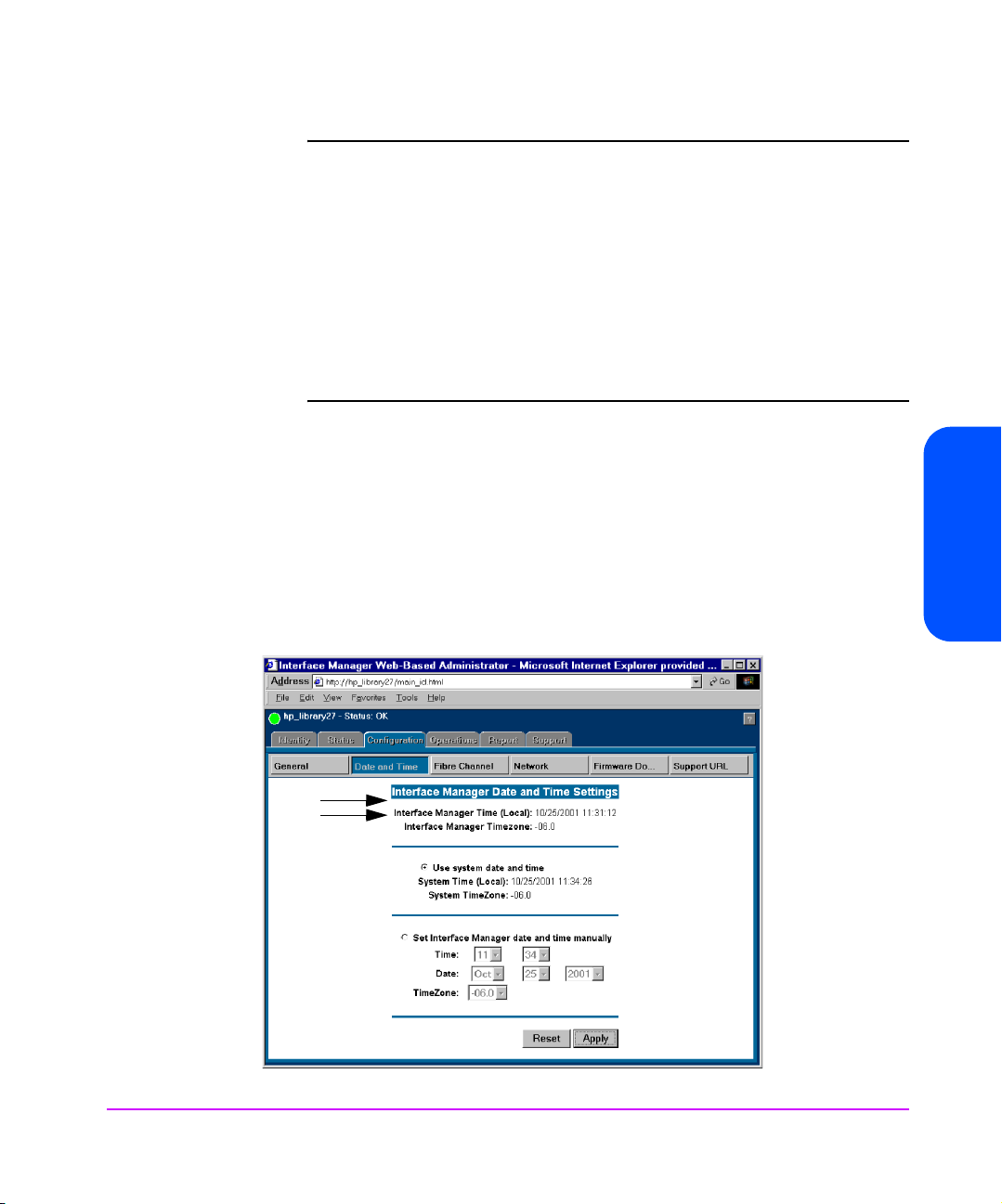
Time Shown is NOT Correct
If the Interface Manager time shown (see Figure 9) is not correct, it can easily
be set to match the time on the computer that is running the browser.
1. Select the [Use system date and time] button.
2. Select the [Apply] button.
Figure 9 Interface Manager Date and Time Settings
Chapter 3
Chapter 3 Management Operations 57
Page 58

Setting a Time That is Different From the Time Shown
If the clock needs to be set to a time that is different from the time shown, do
the following:
1. Select [Set Interface Manager date and time manually] button.
2. Type the correct time into the fields provided.
3. Select the [Apply] button.
None of the fibre interface cards are adversely affected by this function, so it
can be done while data is flowing through the interface cards.
The hour is given in military time, where the possible choices range from 0
through 23 hours after midnight. There is no option for handling daylight
savings time. Set your time zone as shown in Table 7 on page 41.
Changing the Ethernet Configuration Using the Web Administrator
Note An administrator’s password is required before any changes can
be submitted.
To change the Ethernet configuration using the Web Administrator, do the
following (see Figure 10 on page 59):
1. Access the Web Administrator as described in Making Changes via the
Web Interface on page 56.
2. Select the [Configuration] tab.
3. Select the [Network] button.
58 Management Operations Chapter 3
Page 59

Figure 10 Interface Manager Network Settings
Using DHCP
Chapter 3
If the DHCP system is to be used:
1. Select [Obtain network parameters automatically from a DHCP/BOOTP
server] radio button. This enables the DHCP mode.
2. Select the [Apply] button to load the configuration into the RMC.
These settings are not put into effect until the next power cycle or next RMC
reboot. None of the Fibre Channel interface cards are adversely affected by
this function, so this can be done while data is flowing through the interface
cards.
Chapter 3 Management Operations 59
Page 60

Not Using DHCP
If DHCP is not going to be used:
1. Select [Specify network parameters manually] button.
2. You can now enter the <IP address> desired in the IP address field.
3. In the Subnet Mask field, enter the <Subnet Mask> desired.
4. In the Gateway Address field, enter the <Gateway Address> desired.
5. Select the [Apply] button to load the configuration into the RMC.
Changing the Fibre Channel Address Modes Using the Web Administrator
Note An administrator’s password is required before any changes can
be submitted.
To change the Fibre Channel address modes using the Web Administrator, do
the following (see Figure 11 on page 61):
1. Access the Web Administrator as described in Making Changes via the
Web Interface on page 56.
2. Select the [Configuration] tab.
3. Select the [Fibre Channel] button.
60 Management Operations Chapter 3
Page 61

Figure 11 Interface Manager Fibre Channel Address Modes
One of the advantages provided by using the HP Surestore Interface Manager
is that the addressing modes on any combination of the interface cards can be
modified at the same time.
To change the addressing mode on the interface cards, you must:
Chapter 3
1. First change the values shown in the Future Settings fields.
2. When all of the addresses in the Future column are correct, you can
[Apply] them to all of the interface cards at once.
Make note of the settings in the Current Settings fields shown on the screen. If
these are not acceptable, you may choose to edit the Future Settings fields
one at a time, or you may use Hewlett-Packard’s recommended settings.
Chapter 3 Management Operations 61
Page 62

Hard Address Settings
If you want to use the recommended Hard address settings:
Caution Restarting an interface card during this process will stop any
data flowing through that interface card, so any backup in
progress will fail.
1. Select the [Set All Addressing Hard] button.
2. Select the [Apply] button to implement these Future settings to the
appropriate Fibre Channel interface card. Only the interface cards that
are marked as Restart, will have those settings take effect immediately.
Soft Address Settings
There are some conditions that require the interface cards to be set to Soft
addressing. This is easily done for all of the interface cards at once:
Caution Restarting an interface card during this process will stop any
data flowing through that interface card, so any backup in
progress will fail.
1. Select the [Set All Addressing Soft] button to set all of the Future Settings to soft mode.
2. Select the [Apply] button to implement those Future settings to the
appropriate Fibre Channel interface cards.
3. Only the interface cards that are marked as Restart will have those
settings take effect immediately.
62 Management Operations Chapter 3
Page 63

Selecting Your Own Settings
If you wish to select your own settings, then each interface card needs to be
configured separately using the following sequence for each card:
Caution Restarting an interface card during this process will stop any
data flowing through that interface card, so any backup in
progress will fail.
1. Choose between Hard and Soft addressing. HP recommends that Fibre
Channel interface cards be Hard addressed, except in cases where the
switch being used is unable to use Hard addressing.
2. If you selected Hard addressing, you will need to supply an address. Each
Fibre Channel interface card in a loop must have a unique address (see
Fibre Channel Arbitrated Loop Addressing on page 29 for more details).
3. Decide if the card should be restarted when this new address setting is
applied to the selected interface card. If you check the [Restart] button,
then the interface cards will reboot when you select the [Apply] button.
Multiple interface cards will go through their restart sequence at the same
time.
4. Once you have changed the Future Settings of all of the interface cards
that you wish to change, then select the [Apply] button.
The Future Settings will be sent to all of the Fibre Channel interface cards.
Only the interface cards that have been marked as Restart will have those
settings take effect immediately.
Chapter 3
Chapter 3 Management Operations 63
Page 64

Placing a Fibre Channel Interface Card Off-Line Using the Web Administrator
It is not necessary to remove power from the Interface Manager in order to
remove an interface card from its slot. But, it is highly recommended to inform
the firmware of your intention to do so. Placing the interface card Off-Line tells
the firmware on the RMC, on the controller card, and on the interface card that
the card is going to be removed. When it is ready for removal, the upper right
LED on the interface card will turn yellow.
Note An administrator’s password is required before any changes can
be submitted.
Note Slot number1 should contain the RMC (disregard the card type
number 2 on the card, the correct slot number is 1). Slot number
2 should contain the Controller card (disregard the card type
number 3 on the card, the correct slot number is 2). Interface
cards are in slots numbered 3 through 12.
To take a Fibre Channel interface card off-line, do the following:
1. Access the Web Administrator as described in Making Changes via the
Web Interface on page 56.
2. Select the [Operations] tab.
3. Select the [Interface Card Replacement] button.
4. Move the mouse over the image of the interface card that you wish to
place Off-line, (see Figure 12 on page 65), and click on that image.
64 Management Operations Chapter 3
Page 65
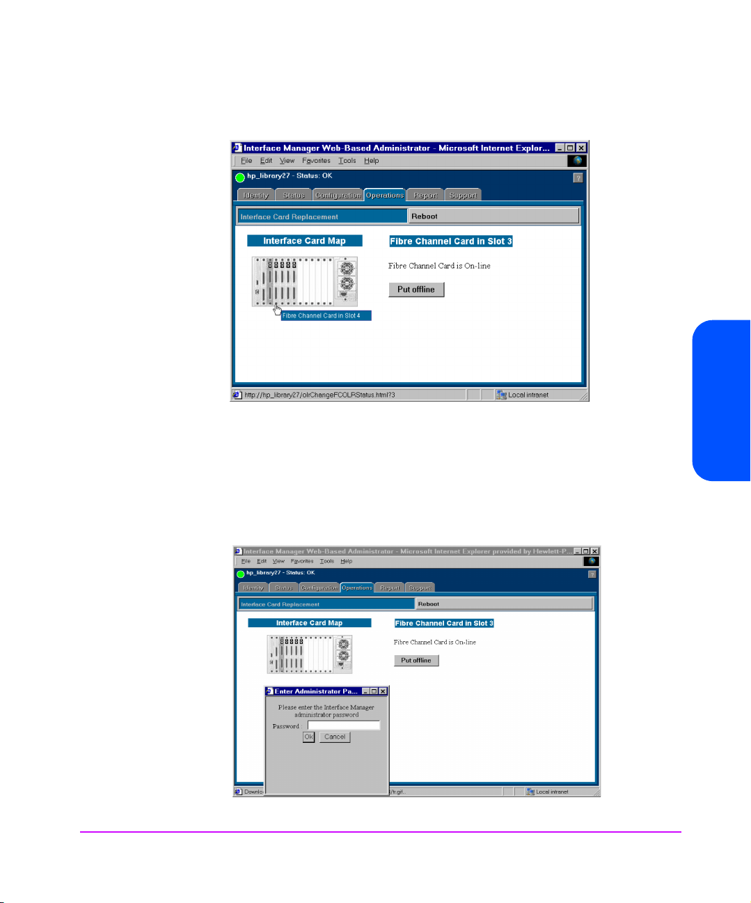
Figure 12 Interface Manager Interface Card Replacement
5. Select the [Put Off-Line] button.
6. The Enter Administrator Password window will appear. You will need to
enter the Interface Manager administrative password to continue (see
Figure 13).
Chapter 3
Figure 13 Interface Manager Interface Card Replacement Administrator Password
Chapter 3 Management Operations 65
Page 66
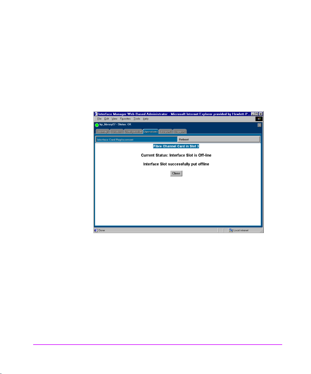
7. A Current Status window will pop-up showing you the card is being
placed off-line. When the card is off-line, a second window will pop-up
and show you that the card has successfully been placed off-line.
8. Select the [Close] button (see Figure 14).
9. When the upper right LED on the card turns yellow, then you can remove the card.
Figure 14 Interface Manager Current Status Window
66 Management Operations Chapter 3
Page 67

Placing a Fibre Channel Interface Card On-Line Using the Web Administrator
Note An administrator’s password is required before any changes can
be submitted.
To replace an interface card that has been removed, do the following (see
Figure 15):
1. BEFORE installing the interface card into the Interface Manager, attach the
SCSI cable that was removed from the old card, to the correct bus on the
new card, based on the connections printed on the cable label that is
attached to the SCSI cable.
2. Insert the new FC interface card into the slot where the old card was
removed. Gently push the card into the slot by placing pressure on the top
AND bottom of the card until it is flush with the chassis. (Pushing the card
in from the top OR bottom alone may damage the card or Interface
Manager (see Figure 7 on page 47).
3. Access the Web Administrator as described in Making Changes via the
Web Interface on page 56.
4. Select the [Operations] tab.
5. Select the [Interface Card Replacement] button.
Chapter 3
Chapter 3 Management Operations 67
Page 68

Figure 15 Interface Manager Interface Card Replacement-Online
6. Move the mouse over the image of the empty slot that you wish to place
[On-Line], then click on that image.
7. Select the [Put On-Line] button.
8. The Enter Administrator Password]window will appear. You will need to
enter the Interface Manager administrative password to continue.
A Current Status window will pop-up showing you the card is being
placed on-line.This process may take several minutes. When the card is
on-line, a second window will pop-up and show you that the card has
successfully been placed on-line.
9. Select the [Close] button (see Figure 16).
10. Wait for the RDY LED to turn green. It takes over one minute for the
interface card to reach that point in the boot up process.
68 Management Operations Chapter 3
Page 69
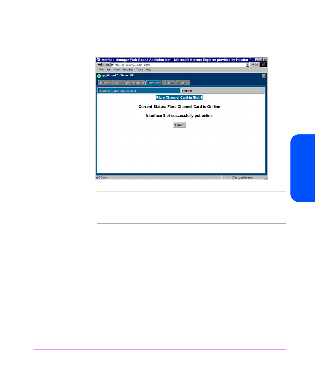
Figure 16 Interface Manager Card Replacement - Online
Note It takes several minutes before the interface card is ready to
report its status back to the RMC. The upper right LED will turn
green on the interface card long before the interface card is
ready to communicate with the RMC.
Chapter 3
11. Once the interface card is ready to be configured, then you may need to
set its addressing mode as described in Hard Address Settings on
page 62, or Soft Address Settings on page 62.
Chapter 3 Management Operations 69
Page 70

Installing a New Interface Card Using the Web Administrator
Note An administrator’s password is required before any changes can
be submitted.
1. Using the cable label kit that came with the Interface Manager, choose the
appropriate labels (designating slot, bus, and drive number) and attach
one label to each end of the SCSI cable.
2. BEFORE installing the interface card into the Interface Manager, plug a
SCSI cable into the new FC interface card. DO NOT install the interface
card at this time.
3. Turn off the drives that will be connected to the new interface card.
4. Plug the SCSI cable into the appropriate drive.
5. Power on the drive(s) in the library and make sure they are correctly
configured with SCSI addresses.
6. Insert the new FC interface card into the first available slot going from left
to right. Gently push the card into the slot by placing pressure on the top
AND bottom of the card until it is flush with the chassis. (Pushing the card
in from the top OR bottom alone may damage the card or Interface
Manager (see Figure 7 on page 47).
7. Access the Web Administrator as described in Making Changes via the
Web Interface on page 56.
8. Select the [Operations] tab.
9. Select the [Interface Card Replacement] button.
If the slot into which you installed the interface card is described as Empty,
then you will need to wait until the interface cards boots up and reports its
status to the RMC. The upper right LED will turn green on the interface
card long before the interface card is ready to communicate with the
RMC. It can take from 2 to 7 minutes before the interface card is ready to
report its status back to the RMC.
10. To update the image of the Interface Manager shown, select the [Interface
Card Replacement] button on this page. The image will change to show
the interface card’s presence when the interface card is available to be
configured.
70 Management Operations Chapter 3
Page 71

— If the slot into which you installed the interface card is described as Off-
Line, then you will need to place the interface card On-Line. To do that
refer to Placing a Fibre Channel Interface Card On-Line Using the Web
Administrator on page 67.
11. Using the Web interface, confirm that the drives are detected by the FC
interface card. To refresh the table shown under the Interface Card menu,
select [Enter].
12. Once the interface card is ready to be configured, you may need to set its
addressing mode as described in Changing the Fibre Channel Address
Modes Using the Web Administrator on page 60
13. Plug in the fibre cable.
14. Using the Web interface, check that the card has an appropriate FC
connection and address. To refresh the table shown under the Interface
Card menu, select [Enter]. The table above the Interface Card menu will
show the interface card’s fibre connection status when the interface card is
available to be configured.
Chapter 3
Chapter 3 Management Operations 71
Page 72

Download a New Revision of the Firmware
Using the Web Interface
Note The firmware file and diagnostic utilities are available from HP
Support at www.hp.com/go/support. These files must be loaded
onto the local host computer before downloading firmware. First
select your product, and then select [Downloads & Drivers].
Note If firmware is downloaded to the controller card, then the entire
Interface Manager will re-boot and any backups in progress will
fail.
All Interface Manager components can be easily downloaded from the Web
interface (see Figure 17 on page 73).
1. Once the Interface Manager is configured for network access, enter the IP
address within your web browser to launch the Web-Based Library
Administrator pages. See Configuration Using the Telnet Interface on
page 38, or Configuration Using the Web Based Administrator on
page 53 for more information.
2. Select the [Configuration] tab from the main screen.
3. Select the [Firmware Download] button.
The pull down box labeled [Choose card to download] allows for
firmware to be downloaded to a single card. This may be useful if the
interface card that has just been added to the Interface Manager has old
firmware.
If a download is performed to only a single interface card, then any
backup that is being performed on any of the other interface cards will
proceed normally
4. Enter the full path name for the download file, or use the [Browse] button to locate the file.
72 Management Operations Chapter 3
Page 73
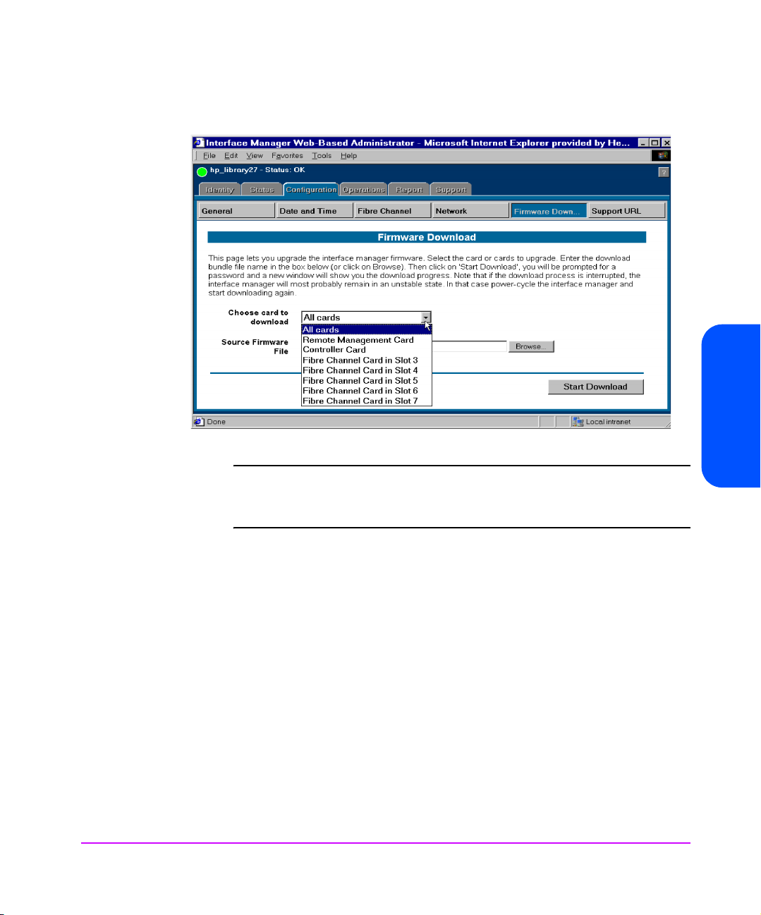
Figure 17 Interface Manager Firmware Download
Note The library administrator password is required for this process
and is not set by default. If the password is not set, you will not
be permitted to download firmware.
Chapter 3
5. Select the [Start Download] button to begin the actual process of
downloading the library firmware.
Once the download process begins, the progress and status of the download
will display on the lower half of your screen. The firmware download may take
several minutes to complete.
Chapter 3 Management Operations 73
Page 74

FTP Interface (All Cards)- Customer Engineer (CE) Only
The Interface Manager (IM) can use FTP to update the firmware on every card
in the IM.
Upgrade Firmware Using FTP
To upgrade the firmware using FTP, do the following:
1. Connect the IM to the Ethernet network used by your computer.
2. Start your FTP program using the IM’s IP address:
ftp <IP address>
Note If you do not know the IP address of the IM (or need to change
the IP address), connect to the IM using the RS-232 (serial)
connection. Current information can be seen and changed from
the Network Configuration menu.
3. Use [download] as the user name and the same password that you used for Telnet and Web access.
Note To change the password, see Changing the Administration
Password Using Telnet on page 40
4. Specify binary mode:
Binary
5. Specify the firmware’s path and filename with the [put] command: put <filename> /firmware/chunker
The file will transfer and the entire IM will reboot. The IM will then be using the
new firmware.
Note You may want to confirm the new firmware level by checking the
Main menu messages on the IM through the Telnet interface.
74 Management Operations Chapter 3
Page 75

FTP Interface (Single Card)
The IM can use FTP to update the firmware on a single card.
Upgrade Firmware Using FTP
To upgrade the firmware using FTP, do the following:
1. Connect the IM to the Ethernet network used by your computer.
2. Start your FTP program using the IM’s IP address:
ftp <IP address>
Note If you do not know the IP address of the IM (or need to change
3. Use [download] as the user name and the same password that you used for Telnet and Web access.
Note To change the password, see Changing the Administration
the IP address), connect to the IM using the RS-232 (serial)
connection. Current information can be seen and changed from
the Network Configuration menu.
Chapter 3
Password Using Telnet on page 40
4. Specify binary mode:
Binary
5. Specify the firmware’s path and filename with the
put <filename> /firmware/chunker/<slot>
<slot> is a number from 1 through 12 that represents the slot number of the
card receiving the new firmware. The slot number represents the card’s
position in the interface manger.
— Slot number 1 should contain the RMC (disregard the card type number
2 on the card, the correct slot number is 1).
— Slot number 2 should contain the Controller card (disregard the card
type number 3 on the card, the correct slot number is 2).
— Slots numbered 3 through 12 should contain the interface cards.
The file will transfer and the card in the assigned slot will reboot. The card will
then be using the new firmware.
Chapter 3 Management Operations 75
[put] command:
Page 76

Note If the Controller card firmware is downloaded, the entire
Interface Manager will reboot.
Note You may want to confirm the new firmware level by checking the
Main menu messages on the IM through the Telnet interface.
76 Management Operations Chapter 3
Page 77

SAN Environments
Chapter Overview
This chapter contains information on the following:
■ Installation and Configuration on page 78
■ Omniback Configuration on page 81
■ HP-UX Configuration on page 85
■ Windows Configuration on page 92
■ Solaris Configuration on page 94
■ Switch Configuration on page 95
4
SAN Environments 77
Page 78

Installation and Configuration
This section explains how to install and configure the HP Surestore Interface
Manager within HP SAN backup solutions. Basic knowledge about installing
and configuring tape libraries, Host Bus Adapters (HBAs), and software in a
non-SAN configuration is required.
This section’s instructions are based on the following example configuration:
■ HP-UX server with two HBAs
■ Windows NT server with one HBA
■ 8-port HP Brocade Fibre Channel switch
■ HP 20/700 tape library with 2 DLT8000 drives
■ Fibre Channel Interface Manager
Note Each actual installation should be verified against the guidelines
of HP supported SAN Backup Solutions. See Table 5 on page 20
for a list of supported products. Contact your HP representative
for the most recent information.
78 SAN Environments Chapter 4
Page 79

Figure 18 Sample Standard SAN Configuration
Chapter 4 SAN Environments 79
Chapter 4
Page 80
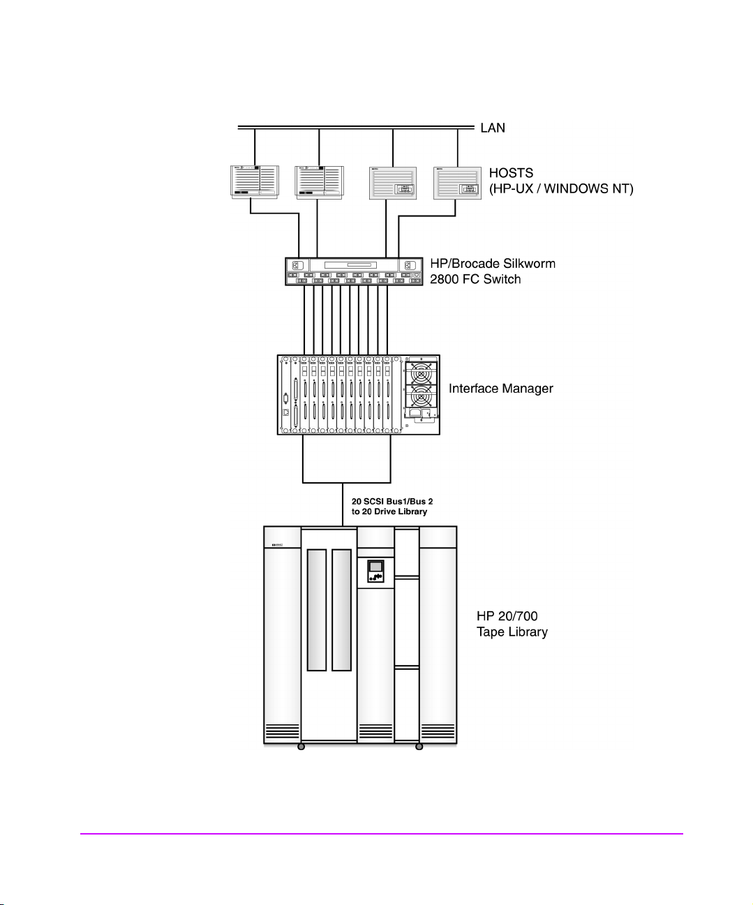
Figure 19 Sample Expanded SAN Configuration
80 SAN Environments Chapter 4
Page 81
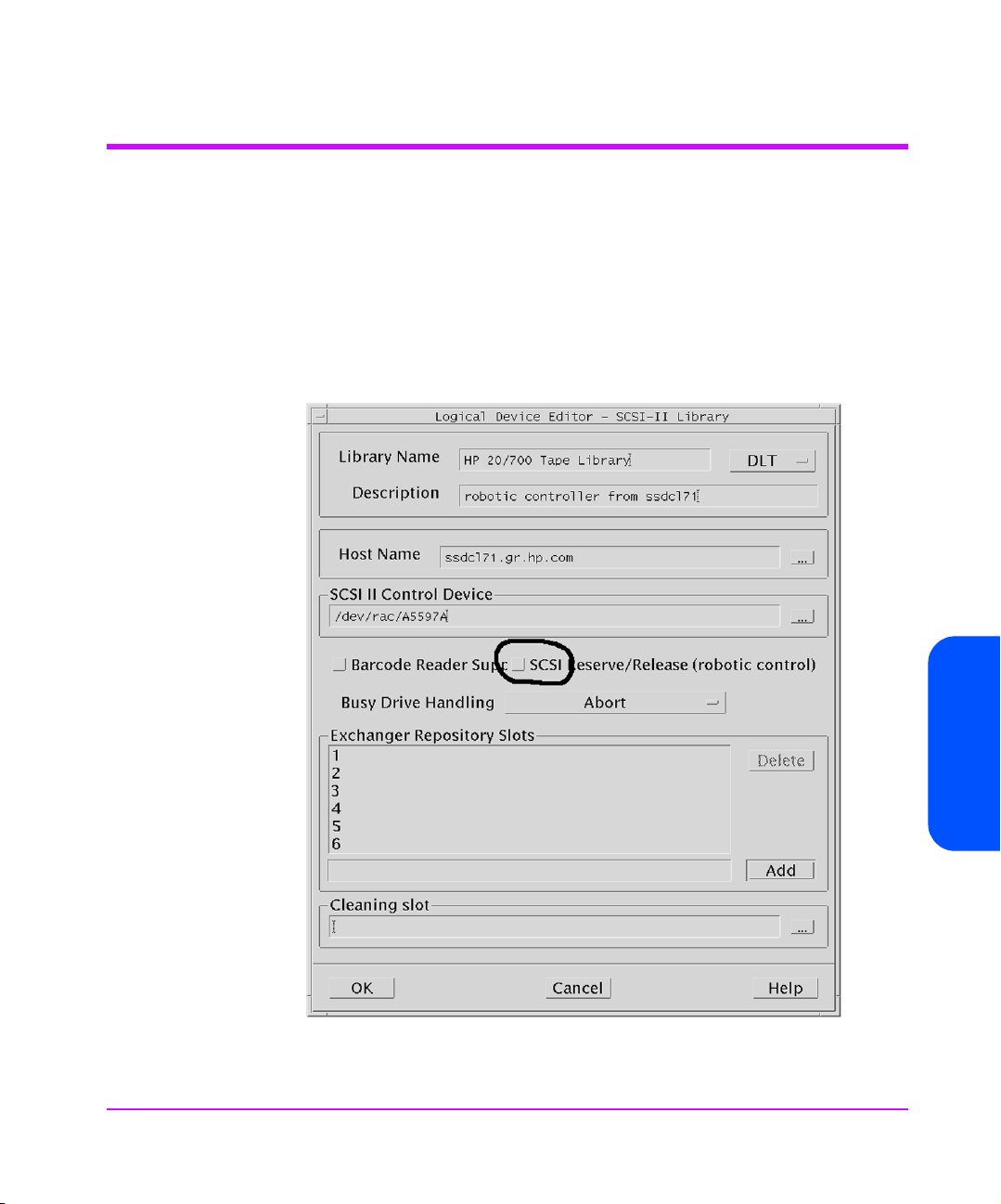
Omniback Configuration
SAN configurations require Omniback II v3.5 or higher. In addition, you must
make the following configuration changes.
1. Open the Device & Media Management screen shown in Figure 20 by
pressing the [Device & Media] button on the Omniback II Main screen
that appears when you first start up Omniback. (On Windows servers, this
is a drop-down menu.)
Figure 20 Device & Media Management Screen
Chapter 4
Chapter 4 SAN Environments 81
Page 82
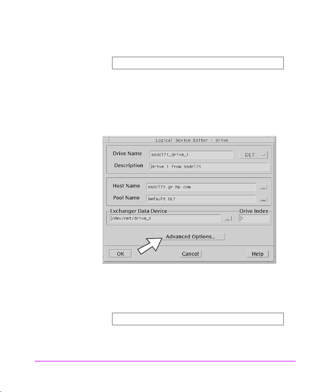
2. From the Device & Media Management screen select:
Edit -> Create -> SCSI-II Library
Configure the library and drives so all nodes on the SAN can share them:
— Configure a single tape library
— Control the robotic arm from a single server, such as the cell server
—Do not check the SCSI Reserve/Release box (see Figure 21)
Figure 21 Logical Device Editor - SCSI-II Library
3. Configure each tape drive for each host that will access it.
In this example with two tape drives and two hosts, four tape drives must be configured.
4. Select a Library device in the Device & Media Management screen shown
in Figure 20 on page 81, then right click and select:
Create -> Drive
The Logical Device Editor - Drive screen shown in Figure 22 appears.
82 SAN Environments Chapter 4
Page 83
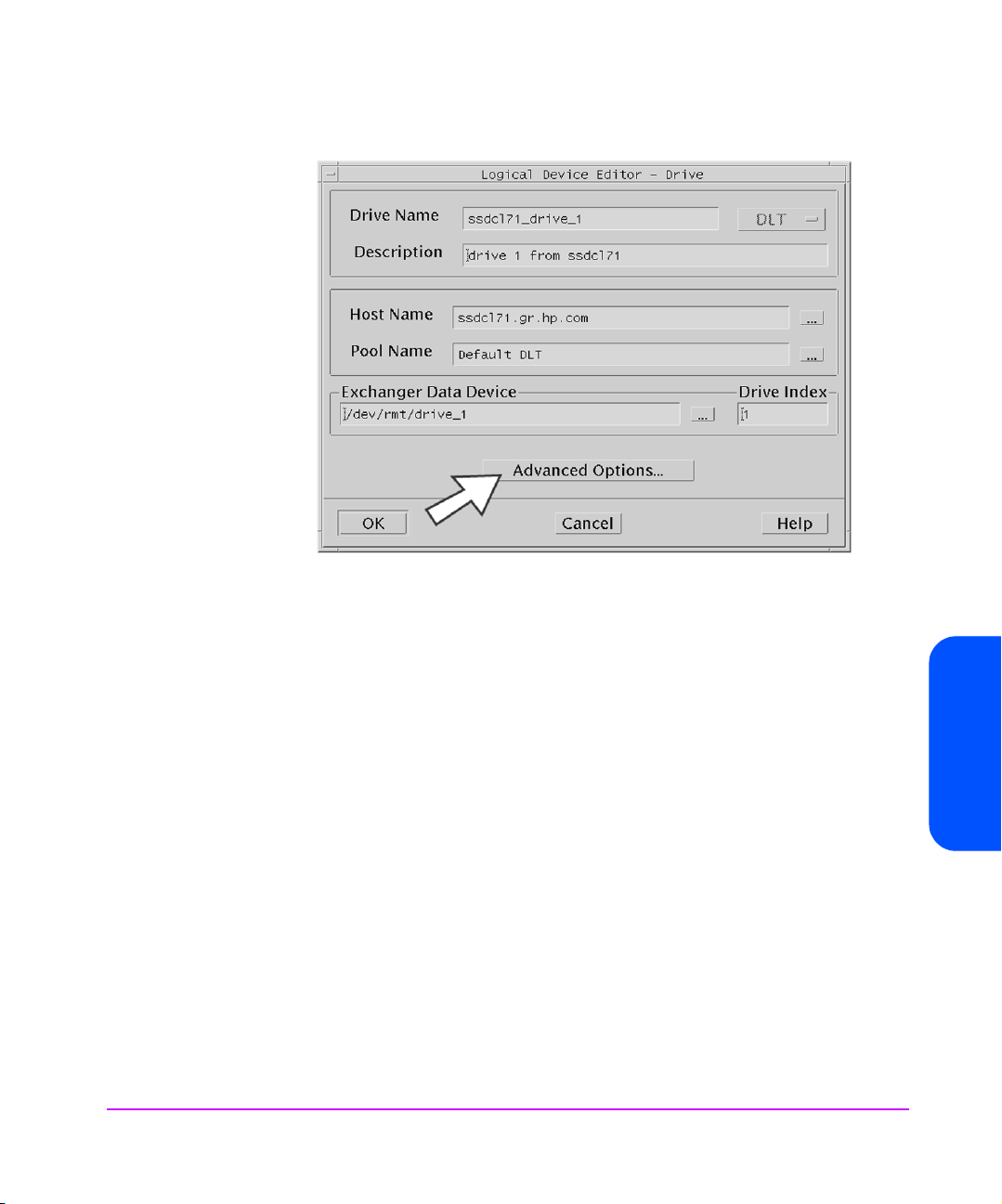
Figure 22 Logical Device Editor - Drive
5. Select the [Advanced Options...] button to bring up the Logical Device Advanced Options screen shown in Figure 23 on page 84.
— Provide a common Lock Name for each tape drive. To enable shared
access of tape drives by different hosts, you must use the same Lock
Name for each instance of the same tape drive. In this example, drives
“lpc7060_drive_1” and “lpc7062_drive_1” are configured with the
same Lock Name, “drive_1”.
— Verify that SCSI Reserve/Release is NOT checked. This feature is
meant to be used in place of the Lock Name or in conjunction with
other software applications sharing the same tape libraries. Multiple
applications on the same SAN are not supported. In addition, if an
error occurs accessing a tape drive, the drive may be left reserved by
the host and, therefore, unavailable from other servers. Once a tape
drive is left reserved, manual intervention is required to release it.
Chapter 4
— Verify that Use direct library access is NOT checked. This feature
allows each host on the SAN to access the robotics directly. This is not
supported. For higher available access to the robotics controller, the cell
server and control of the tape library may be configured on a clustered
server.
Chapter 4 SAN Environments 83
Page 84
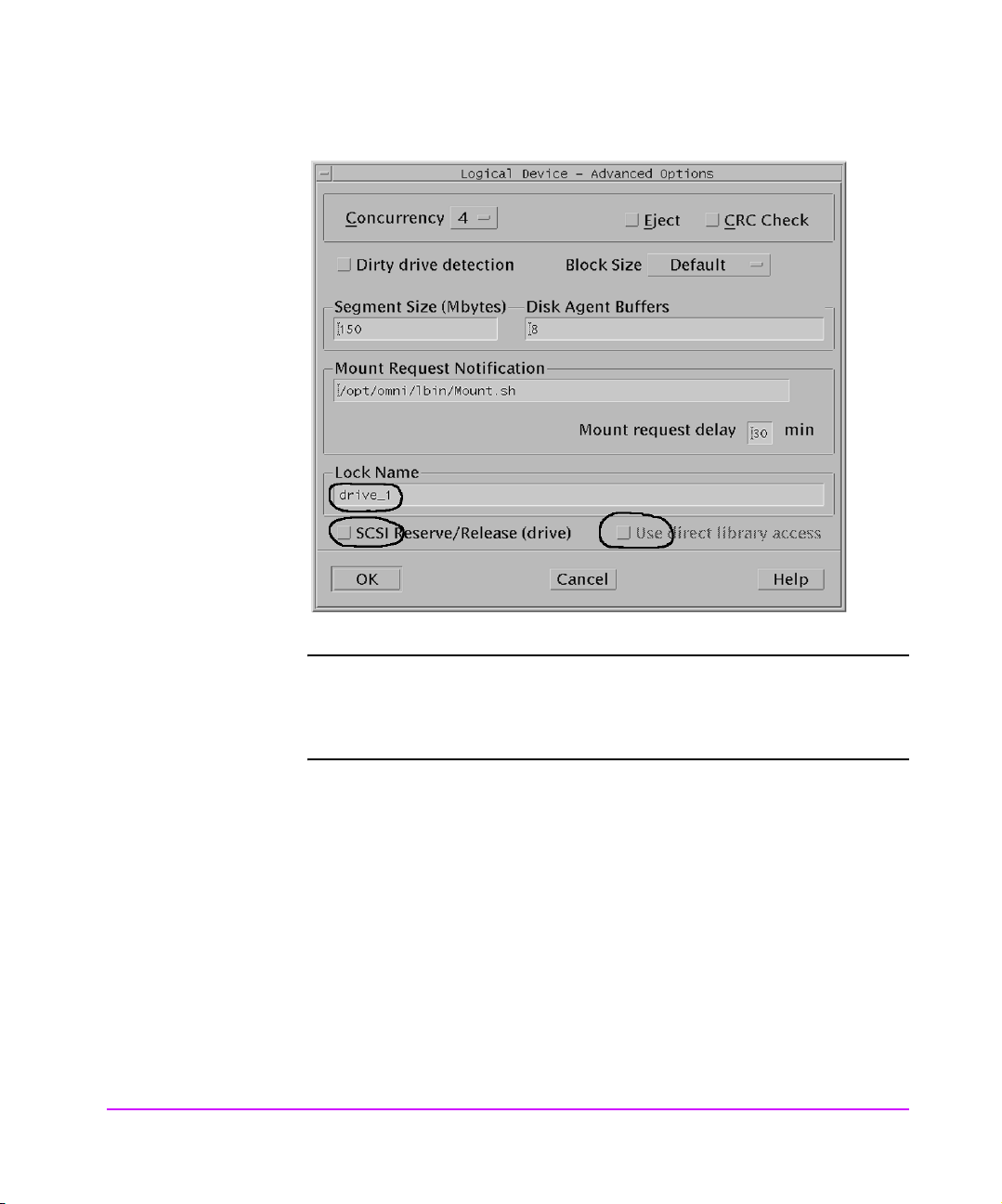
Figure 23 Logical Device - Advanced Options
Note For optimized performance when configuring hosts with multiple
HBAs, use only one path per tape drive and distribute the tape
drives across the HBAs. For additional information see HP-UX
Configuration on page 85.
84 SAN Environments Chapter 4
Page 85

HP-UX Configuration
Use one of the Fibre Channel cards listed in Table 5 on page 20. You must
also install the fabric driver for the appropriate platform.
Configure a single path for each tape drive. The device files must be manually
selected or created, and configured properly in the software.
In Figure 24 on page 86, ten tape drives are configured from the HP-UX host.
The following 'ioscan' shows the paths and the corresponding device files.
Note Always use the latest release of fabric drivers.
Note If MC/ServiceGuard is installed, ATS should not be configured
for SAN environments with a fabric switch.
Chapter 4
Chapter 4 SAN Environments 85
Page 86

Figure 24 Sample ioscan Output
86 SAN Environments Chapter 4
Page 87
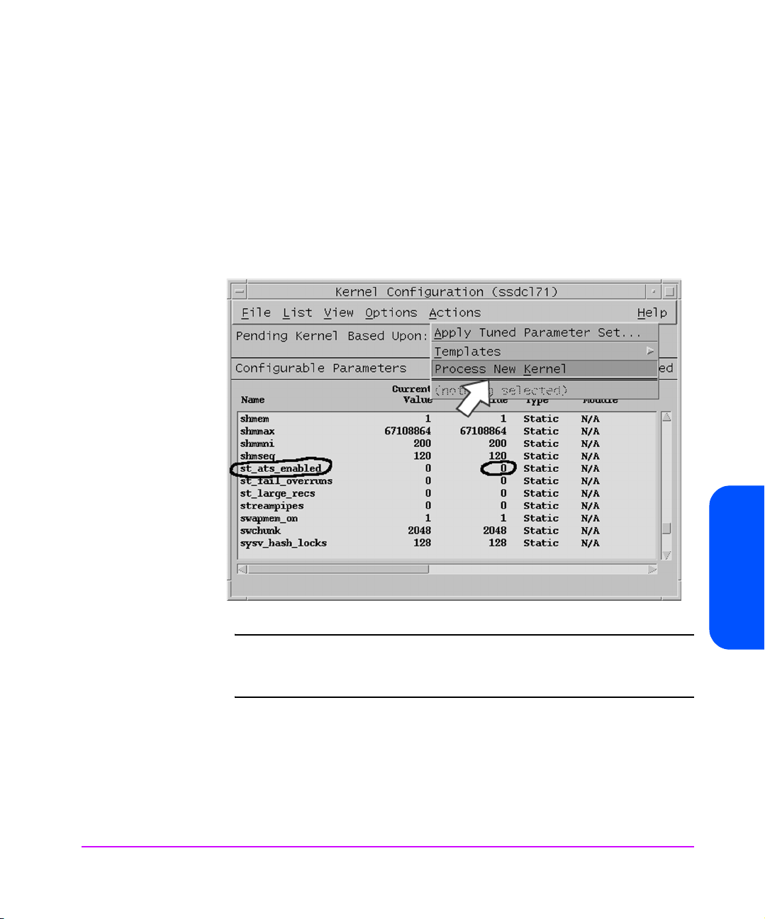
1. Set the static kernel tunable parameter st_ats_enabled to OFF (0).
This can be done from the Kernel Configuration window of HP-UX system
administration tool (SAM) shown in Figure 25 and requires a kernel
rebuild and system reboot. When this parameter is enabled an implicit
SCSI reserve and release is performed during the open and close
sequence in the tape driver. This default was originally designed for ATS
services with MC/ServiceGuard. For SAN configurations, this parameter
needs to be disabled for the reasons described earlier.
Figure 25 Configurable Parameters Screen
Note When MC/ServiceGuard is enabled for ATS, the ATS services
provide a mechanism for automatically cleaning up reservations
from a second host.
2. Configure the Tape Device Monitor (dm_stape) of the Event Monitoring
System (EMS) to not run on the host participating in the tape SAN.
The EMS service periodically polls the tape devices to monitor their health.
When this occurs while another server is accessing the tape device,
backup operations may be disrupted, time out and abort.
Chapter 4 SAN Environments 87
Chapter 4
Page 88

There are two ways to disable the dm_stape monitor while keeping the
Event Monitoring System enabled.
— Stop the dm_stape process
— Prevent dm_stape from polling
Note To completely disable event monitoring, run /etc/opt/resmon/
lbin/monconfig and select [(D) Disable Monitoring]. When
event monitoring is shut down in this fashion, all monitors will be
shut down as well.
The monconfig utility is also used to disable individual event
monitors. Note that if individual monitors are disabled, they
continue to run in the background and send SCSI commands to
the devices. The EMS framework ignores the events the monitor
might be generating.
Stopping the dm_stape process
Shutting down the tape device monitor is very difficult. Simply stopping the
process does not work because the EMS framework restarts it.
Note Customer Engineer: You may need to have the system
administrator disable the tape device monitor and re-enable
after this process.
Note You must follow these instructions in the order given or the
monitor will not be shut down.
1. Disable predictive monitoring requests in var/stm/config/tools/monitor/
predictive.sapcfg by commenting out the “dm_stape” tape drive monitor
entries.
2. Delete all monitoring requests for dm_stape:
a. Log in as [root].
b. Run /etc/opt/resmon/lbin/monconfig.
c. Run the [S] command to get a list of all monitors running.
88 SAN Environments Chapter 4
Page 89

d. Make a list of all the monitors and monitoring requests that have
SCSI_tape listed. (You modify these in the next step.)
e. Delete all monitoring requested for “SCSI_tape”. Use the [modify]
command:
—Type [M]. The tool displays a list of all monitoring requests and prompts
for a number of the request to change.
— Type the number of the request to modify. The tool displays a list of all
the monitors for that request and prompts for the monitor(s) to modify.
— Enter the numbers of the monitors except the one listing SCSI_tape
(usually number 12).
Table 9 Monitors typically clumped with “SCSI_tape”
AutoRAID ses_enclosure
Default SCSI_tape
FC_adaptor FC60
TL_adaptor FW_SCSI
core_hw High_Availability
FC_hub lpmc
FC_SCSI_mux scsi123_em
FC_switch system_status
Table 10 Monitoring Requests
Send events generated by monitors <monitor list above>
with severity >= INFORMATION to TEXTLOG /var/opt/resmon/log/event.log
Send events generated by monitors <monitor list above>
with severity >= MAJOR WARNING to SYSLOG
Send events generated by monitors <monitor list above>
with severity >= MAJOR WARNING to EMAIL root
— Re-enter the Criteria Threshold, Criteria Operator, Notification Method,
User comment, and Client Configuration File.
Chapter 4 SAN Environments 89
Chapter 4
Page 90

—Type [Y] to keep the changes.
— Repeat these steps for all monitor requests that contain “SCSI_tape”.
—Type [C] for the changes to take effect.
3. Rename the dm_stape.psmcfg file as follows:
mv /var/stm/config/tools/monitor/dm_stape.psmcfg
/var/stm/config/tools/monitor/dm_stape.psmcfg.orig
4. Verify that EMS is not taking further monitoring requests for dm_stape. In
moncofig, enter [C]
command until no monitoring requests exist for
SCSI_tape.
5. Rename the dm_stape.sapcfg file as follows:
mv /var/stm/config/tools/monitor/dm_stape.sapcfg
/var/stm/config/tools/monitor/dm_stape.sapcfg.orig
6. Kill dm_stape and remove the dm_stape.hwa file as follows:
ps -ef | grep dm_stape (to get pid of dm_stape)
kill -2 <dm_stape pid>; rm /var/stm/data/tools/
monitor/dm_stape.hwa
7. Rename the dm_stape binary (optional; dm_stape will not run at all) as
follows:
mv /usr/sbin/stm/uut/bin/tools/monitor/dm_stape
/usr/sbin/stm/uut/bin/tools/monitor/dm_stape.orig
Note This step may cause the EMS framework to generate errors.
To restart dm_stape after it has been stopped:
1. Rename dm_stape binary back (if step 7 was performed when stopping
dm_stape):
mv /usr/sbin/stm/uut/bin/tools/monitor/
dm_stape.orig /usr/sbin/stm/uut/bin/tools/monitor/
dm_stape
2. Add monitoring requests for dm_stape:
a. Log in as [root].
b. Run /etc/opt/resmon/lbin/monconfig
.
c. Add monitoring requests for “SCSI_tape” with the [A] command.
3. Restore the dm_stape.psmcfg file and the dm_stape.sapcfg files as follows:
mv /var/stm/config/tools/monitor/
90 SAN Environments Chapter 4
Page 91

dm_stape.psmcfg.orig
/var/stm/config/tools/monitor/dm_stape.psmcfg
mv /var/stm/config/tools/monitor/
dm_stape.sapcfg.orig
/var/stm/config/tools/monitor/dm_stape.sapcfg
4. Check for monitoring requests in monconfig. In monconfig, enter [C]
command and verify that SCSI_tape is accepting monitoring requests.
Preventing dm_stape from polling
If the POLL_INTERVAL value in the /var/stm/config/tools/monitor/
dm_stape.cfg file is set to zero, the monitor still runs, but does not log any
events or poll the devices (that is, it will not send any SCSI commands).
Preventing dm_stape from polling is much easier than stopping the dm_stape
process. However, in IPR releases before IPR0109 this will not work properly.
This bug has been partially fixed in the IPR0106 release.
For the IPR0103 release, there are patches that partially fix the problem:
■ For HP-UX 11.00 with IPR0103 installed the patch number is:
PHSS_24044.
■ For HP-UX 11.11 with IPR0103 installed the patch number is:
PHSS_24045.
Note For the IPR0106 release and for the IPR0103 release with either
patch, the dialogued process must be running when you set the
POLL_INTERVAL value to zero. If it is not, the monitor will fill the
api.log file with error messages until the hard disk space is used
up, and consume most of the CPU time. Under no circumstances
should dialogued or the STM diagnostics be shut down.
After installing the appropriate patch, manually set the POLL_INTERVAL value
in the /var/stm/config/tools/monitor/dm_stape.cfg
file to
zero to stop the monitor from polling.
Chapter 4 SAN Environments 91
Chapter 4
Page 92

Windows Configuration
For Windows platforms, you must use driver version of 2.06 or later with the
D8602A/B FC HBA. You must manually configure the driver to initialize with
the switch using N_port instead of NL_port. Configure this through a registry
setting which is described in the readme file provided with the HBA driver.
Windows 2000 Removable Storage Manager
The Windows 2000 Removable Storage Manager services running on one
host may interfere with backups running on other hosts in the SAN. This can
result in backup or restore failures.
To eliminate this problem, disable the Removable Storage Manager service on
all Window 2000 systems attached to a backup SAN.
To do this:
1. Right click on the [My Computer] icon and select [Manage].
Figure 26 Computer Management
92 SAN Environments Chapter 4
Page 93

2. Select [Services] in the left pane, then double click on [Removable
Storage] in the right pane to stop the Removable Storage service.
3. Set the Startup type to [Disabled].
Figure 27 Removable Storage Properties
Chapter 4 SAN Environments 93
Chapter 4
Page 94

Solaris Configuration
For information regarding configuring Solaris hosts, please refer to available
configuration notes for the JNI FC HBA on Solaris systems.
94 SAN Environments Chapter 4
Page 95

Switch Configuration
HP/Brocade Switch and Interface Manager Configuration
Use the default configuration for the Fibre Channel switch in SAN backup
configurations (see Figure 18 on page 79).
In this example the:
■ HP-UX host is attached to ports 1 & 2 of the switch
■ Windows NT server is attached to port 0
■ Interface Manager is attached to ports 6 through 15.
Verify that the switch is not using Quick Loop mode.
Use zoning only if it is needed to simplify configuration on the hosts. See the
SAN Backup Solution Configuration Guide referenced at the end of this
chapter for more information.
Two changes should be made when connecting the Interface Manager directly
to a switch port.
Use the Interface Manager’s Fibre Channel Configuration menu:
■ Set Addressing mode to [Soft]
■ Set Port Mode to [N_Port]
This provides a direct F_Port to N_Port connection between the switch and
Interface Manager.
Chapter 4
Chapter 4 SAN Environments 95
Page 96

Figure 28 Fibre Channel Switch Configuration
switch59:admin> version
Kernel: 5.3.1
Fabric OS: v2.1.9f
Made on: Mon Dec 4 14.37.39 PST 2000
Flash: Mon Dec 4 14.38.10 PST 2000
BootProm: Thu Jun 17 15:20:39 PDT 1999
switch59:admin>
switch59:admin> switchshow
switchName: switch59
switchType: 3.4
switchState: Online
switchRole: Principal
switchDomain: 2
switchId: fffcO2
switchWwn: 10:00:00:60.169.20.24:04
part 0: sw Online F-Port 50:06:0b:00:00:00:79:dO
port 1: sw Online F-Port 50:06:0b:00:00:06:d4:96
port 2: sw Online F-Port 50:06:0b:00:00:06:d3:dc
port 3: -- No-Module
port 4: -- No-Module
port 5: -- No-Module
port 6: id Online F-Port 10:00:00:e0:02:21:b9:a2
port 7: -- No-Module
switch59:admin>
switch59:admin> qlShow
Switch is not in Quick Loop mode.
switch59:admin>
switch59:admin> zoneShow
Defined configuration:
no configuration defined
Effective configuration,
no configuration in effect
switch59:admin>
FC-64 Director (McData) Switch
Use the default mode for the FC-64 switch in SAN backup configurations.
You must make the following changes to the default configuration:
1. The FC-64 Fibre Channel switch does not support public or private loop
connections. All devices must use login as N_port only.
2. Set the Interface Manager Hard ALPA setting to [NO] and the Fibre Channel port mode to [N_port].
3. Set the addressing to [Soft] on internal Fibre Channel cards.
96 SAN Environments Chapter 4
Page 97

Troubleshooting
Chapter Overview
This chapter contains information on the following:
■ Troubleshooting on page 98
■ Operation Indicators on page 99
■ Problem - Solution on page 107
5
Troubleshooting 97
Page 98

Troubleshooting
This section is provided to help guide the user through some of the basic
methods of identifying faults in the setup and configuration of the Interface
Manager (IM).
Most problems are found in the initial installation. In general, it is wise to check
all connections and review the configuration before proceeding with further
trouble analysis. Simplify the installation if possible, by reducing it to the most
basic configuration, then adding elements one at a time and verifying the
operation at each step.
98 Troubleshooting Chapter 5
Page 99
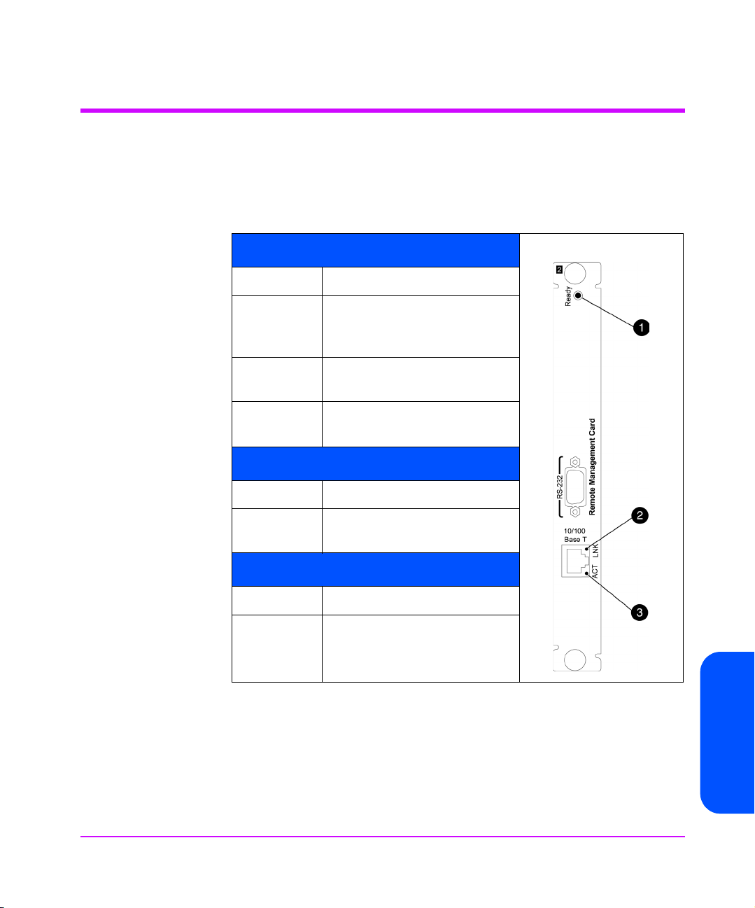
Operation Indicators
The cards in the Interface Manager consist of the remote management card
(RMC), controller card, and Fibre Channel interface cards. Each card has LED
indicators for monitoring overall status.
Table 11 Remote Management Card LEDs
1) Ready LED
Color Description
Yellow Powering up, failed power-on
test, or fatal error was detected
during operation.
Flashing
Yellow
Green Card passed power-on test.
2) Link LED
Color Description
Green Indicates valid network
3) Activity LED
Color Description
Flashing
Green
Attempting DHCP address
assignment
Card ready.
connection.
Indicates transmission activity
by the card’s Ethernet port.
Chapter 5
Chapter 5 Troubleshooting 99
Page 100
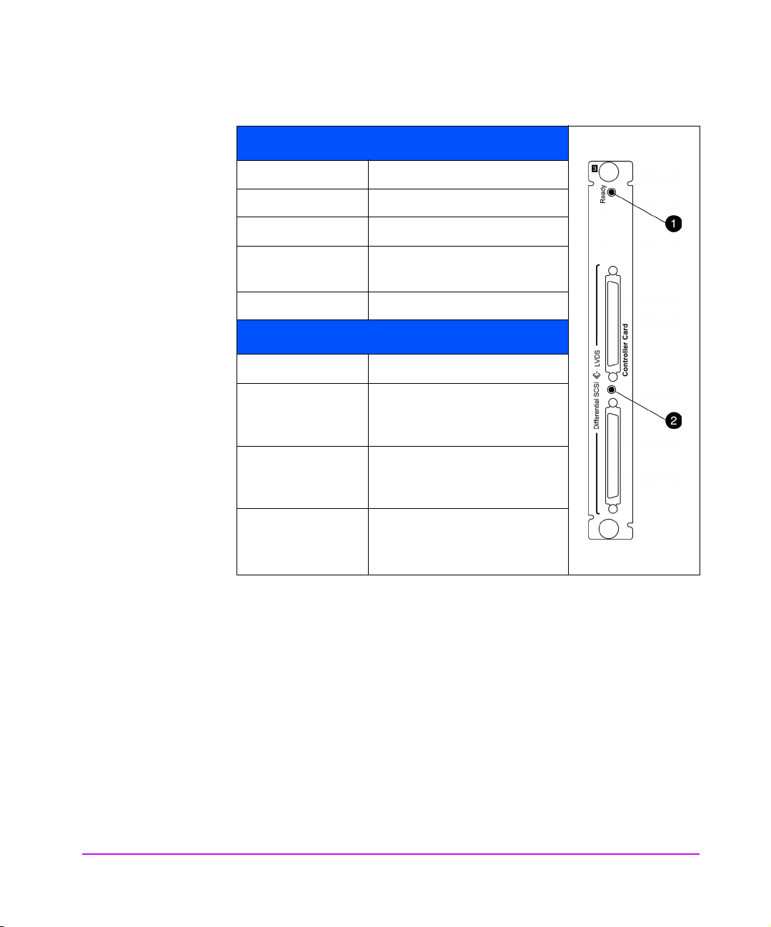
Table 12 LVDS Controller Card LEDs
1) Controller LED
Color Description
Flashing Green Controller needs firmware.
Yellow In the process of powering up.
Yellow flash Controller failed power-on
Green Ready.
2) SCSI LED
Color Description
Green No bus connected or low-
Flashing Green Single-ended SCSI bus
Yellow High-voltage differential SCSI
test.
voltage differential SCSI bus
connected.
attached. SCSI performance
reduced.
bus connected. Configuration
error.
100 Troubleshooting Chapter 5
 Loading...