

Page 1

HP Pro Tablet 608 G1
Maintenance and Service Guide
IMPORTANT! This document is intended for HP
authorized service providers only.
Page 2

© Copyright 2015 HP Development Company,
L.P.
Bluetooth is a trademark owned by its
proprietor and used by HP Inc. under license.
Intel and Atom are trademarks of Intel
Corporation in the U.S. and other countries.
Windows is a trademark of the Microsoft group
of companies. SD Logo is a trademark of its
proprietor.
For DTS patents, see http://patents.dts.com.
Manufactured under license from DTS
Licensing Limited. DTS, the Symbol, & DTS and
the Symbol together are registered
trademarks, and DTS Studio Sound is a
trademark of DTS, Inc. © DTS, Inc. All Rights
Reserved .
The information contained herein is subject to
change without notice. The only warranties for
HP products and services are set forth in
the express warranty statements
accompanying such products and services.
Nothing herein should be construed as
constituting an additional warranty. HP shall
not be liable for technical or editorial errors or
omissions contained herein.
Second Edition: August 2015
First Edition: July 2015
Document Part Number: 815234-002
Product notice
This guide describes features that are common
to most models. Some features may not be
available on your tablet.
Software terms
By installing, copying, downloading, or
otherwise using any software product
preinstalled on this tablet, you agree to be
bound by the terms of the HP End User License
Agreement (EULA). If you do not accept these
license terms, your sole remedy is to return the
entire unused product (hardware and software)
within 14 days for a refund subject to the
refund policy of your place of purchase.
For any further information or to request a full
refund of the tablet, please contact your local
point of sale (the seller).
Page 3

Safety warning notice
WARNING! To reduce the possibility of heat-related injuries or of overheating the tablet, do not place the
tablet directly on your lap. Do not allow a soft surface, such as pillows or rugs or clothing, to block airow.
Also, do not allow the AC adapter to come into contact with the skin or a soft surface, such as pillows or rugs
or clothing, during operation. The tablet and the AC adapter comply with the user-accessible surface
temperature limits dened by the International Standard for Safety of Information Technology Equipment
(IEC 60950-1).
iii
Page 4

iv Safety warning notice
Page 5

Table of contents
1 Product description ....................................................................................................................................... 1
2 External component identication .................................................................................................................. 4
3 Illustrated parts catalog ................................................................................................................................ 7
Locating the serial number and model number .................................................................................................... 7
Tablet major components ...................................................................................................................................... 8
Miscellaneous parts ............................................................................................................................................... 9
Sequential part number listing ........................................................................................................................... 10
4 Removal and replacement preliminary requirements ..................................................................................... 13
Tools required ...................................................................................................................................................... 13
Service considerations ......................................................................................................................................... 13
Plastic parts ....................................................................................................................................... 13
Cables and connectors ...................................................................................................................... 13
Grounding guidelines ........................................................................................................................................... 14
Electrostatic discharge damage ........................................................................................................ 14
Packaging and transporting guidelines .......................................................................... 15
Workstation guidelines ................................................................................ 15
5 Removal and replacement procedures ........................................................................................................... 17
Tablet component replacement procedures ....................................................................................................... 17
MicroSD card tray ................................................................................................................................................. 17
Nano SIM card tray (select models only) ............................................................................................................. 18
Back cover ............................................................................................................................................................ 18
Disconnecting the battery ................................................................................................................................... 19
WWAN module (select models only) ................................................................................................................... 21
Left speaker ......................................................................................................................................................... 23
Audio board .......................................................................................................................................................... 24
Vibration motor board ......................................................................................................................................... 26
Front-facing webcamera ..................................................................................................................................... 27
Rear-facing webcamera ....................................................................................................................................... 28
System board ....................................................................................................................................................... 30
Right speaker ....................................................................................................................................................... 35
Battery and middle plate ..................................................................................................................................... 36
Outer ring ............................................................................................................................................................. 38
v
Page 6

POGO pin connector ............................................................................................................................................. 40
6 Specications .............................................................................................................................................. 42
7 Using Computer Setup (BIOS) ........................................................................................................................ 43
Starting Computer Setup ..................................................................................................................................... 43
Navigating and selecting in Computer Setup ...................................................................................................... 43
Restoring factory settings in Computer Setup .................................................................................................... 44
Updating the BIOS ................................................................................................................................................ 44
Determining the BIOS version ........................................................................................................... 44
Downloading a BIOS update ................................................................................................................................ 45
8 Using HP PC Hardware Diagnostics (UEFI) ....................................................................................................... 47
Downloading HP PC Hardware Diagnostics (UEFI) .............................................................................................. 47
9 Backup and recovery .................................................................................................................................... 48
Creating recovery media and backups ................................................................................................................ 48
Creating recovery media ................................................................................................................... 48
Backing up your information ............................................................................................................. 49
Performing a system recovery ............................................................................................................................ 49
Using the Windows recovery tools .................................................................................................... 49
Changing the boot device order ........................................................................................................ 50
10 Power adapter requirements ...................................................................................................................... 51
Requirements for all countries ............................................................................................................................ 51
Requirements for specic countries and regions ................................................................................................ 51
11 Recycling .................................................................................................................................................. 53
Index ............................................................................................................................................................. 54
vi
Page 7

1 Product description
Category Description
Product Name HP Pro Tablet 608 G1
Processor
Graphics Integrated Gen8-LP 8 EU up to 640 MHz
Panel 7.86 inch, Quad Extended Graphics Array (QXGA) resolution (2048 x 1536) BV white light emitting
Memory 2 GB LPDDR3 memory, integrated onto system board, 1600 253b package (8 Gb(128
Storage 32 GB eMMC, integrated onto system board
Audio and video Two noise cancellation microphones
Intel® AtomTM x5-Z8500 Quad Core SOC B-1 4c BGA 1.36 GHz 16 EU, 2.16 GHz Burst, Type 4 QHAU
(soldered on the system board)
diode (WLED), Ultra-Wide Viewing Angle (UWVA), 70% cg, 450 nits (cd/m2) MIPI
Supports Active Pen and Multitouch
MbX32X2)*2pcs)
4 GB LPDDR3 memory, integrated onto system board, 1600 253b package (16 Gb(128
MbX32X4)*2pcs)
eMMC 4.51 (Memory HW will be 4.51 and 5.0 but SOC can only supports up to 4.51 protocol)
64 GB eMMC, integrated onto system board
128 GB eMMC, integrated onto system board
Your tablet has read/write support for SDXC microSD cards up to 2 TB.
Two speakers with DTS Studio Sound
8.0 MP full-frame high-denition rear-facing webcamera
2.0 MP full-frame high-denition front-facing webcamera
Supports HD audio formats
Supports headset
Sensors Accelerometer + eCompass
Gyroscope
Ambient light sensor
Haptics sensor
Proximity Sensor (WWAN Only)
Wireless networking Integrated WLAN option: Intel 7265.D2WG18V AC 2x2 + Bluetooth® 4 LE PCIe+USB SD 1216 WW
2 WLAN antennas congured with panel on all units
Near eld communication (NFC): NXP NPC100 Integrated NFC module and antennas
WWAN (SIM Module, 4 FF/nano SIM, M.2 3042 S3 module):
●
HP It4211, LTE/EV-D0/HSPA+, QCOM MDM9615 Integrated GPS (North America only)
●
Huawei ME906E, LTE/HSPA+, QCOM MDM9215, integrated GPS: HP lt4112 LTE/HSPA+ Gobi
4G Module (EMEA only)
1
Page 8

Category Description
●
Huawei MU736, HSPA+, Intel XMM6260 3G, integrated GPS: HP hs3110 HSPA+ Mobile
Broadband Module (worldwide)
Supports No WWAN/No GPS option
External expansion Integrated SDXC microSD card reader expandable up to 2 TB.
Ports
Docking Portable docking
Keyboard/Mouse Support for Magnector connected soft keyboard, USB or Bluetooth connected external keyboard
Power requirements 21 Whr, 1S2P, Lithium-polymer, non-user removable battery
Operating system Preinstalled:
●
Audio: headphone/microphone combo jack
●
MicroSD card reader
●
Nano SIM card slot
●
USB Type-C (charging) port
●
1x 10 Pin Magnetic connector (POGO)
and mouse
15 W + USB Type-C (charging). (100% attached) (Micro USB Adapter) cable and localized cable
plug support
●
Windows® 8.1 Pro 64 for Small Tablets
●
Windows 8.1 Pro 64 StF MSNA (only available with equal to or less than 64 GB eMMC
Storage, not available with 128 GB eMMC Storage)
●
Windows 8.1 Pro 64 StF EM (only available with equal to or less than 64 GB eMMC Storage,
not available with 128 GB eMMC Storage)
●
Windows 8.1 Pro 64 for Small Tablets retail (only available with RS BUs)
●
Windows Embedded 8.1 Industry Pro 64 Retail (only available with RS BUs)
●
Windows 8.1 Core for Higher Education 64 ML (only available for Emerging Markets)
●
Windows 10 Home 64 Chinese Market CPPP (only available for the People’s Republic of
China)
●
Windows 10 Home 64 Shape the Future OS AV for Higher Education (only available for
Emerging Markets except Asia and the People’s Republic of China)
●
Windows 10 Home 64 Entry Tablet + 2-in-1 Notebook (not available for Asia or the People’s
Republic of China)
●
Windows 10 Home 64 Entry Tablet + 2-in-1 Notebook Chinese markets (only available for
the People’s Republic of China)
●
Windows 10 Home 64 Entry Tablet + 2-in-1 Notebook Single Language (only available for
Emerging Markets)
●
Windows 10 Home 64 Small Tablet + 2-in-1 Notebook (not available for Asia or the People’s
Republic of China)
●
Windows 10 Home 64 Small Tablet + 2-in-1 Notebook Chinese market (only available for the
People’s Republic of China)
●
Windows 10 Home 64 Small Tablet + 2-in-1 Notebook Single Language (only available for
emerging markets)
●
Windows 10 Pro 64 Small Tablet + 2-in-1 Notebook
●
Windows 10 Pro 64 Small Tablet + 2-in-1 Notebook (Retail—select countries)
2 Chapter 1 Product description
Page 9

Category Description
●
Windows 10 Pro 64 StF MSNA (only available for developed markets)
●
Windows 10 Pro 64 StF MSNA (only available for emerging markets)
Web-only support:
●
Windows 8.1 Enterprise
●
Windows 10 Enterprise
Restore USB–for service only:
USB recovery to align with customer image, to include base operating system, language packs,
drivers, and QFE’s.
Serviceability End user replaceable parts:
●
AC adapter
3
Page 10
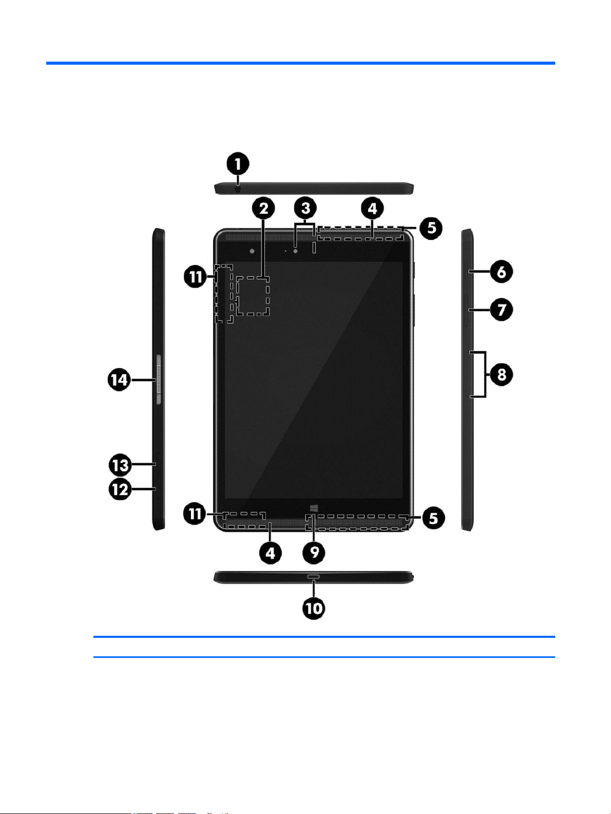
2 External component identication
Component Description
(1) Audio-out (headphone)/Audio-in (microphone)
combo jack
4 Chapter 2 External component identication
Connects optional powered stereo speakers, headphones,
earbuds, a headset, or a television audio cable. Also connects an
optional headset microphone. This jack does not support
optional microphone-only devices.
Page 11

Component Description
WARNING! To reduce the risk of personal injury, adjust the
volume before using headphones, earbuds, or a headset. For
additional safety information, see the Regulatory, Safety and
Environmental Notices.
NOTE: When a device is connected to the jack, the tablet
speakers are disabled.
NOTE: Be sure that the device cable has a 4-conductor
connector that supports both audio-out (headphone) and audioin (microphone).
(2) NFC (Near Field Communications) area (select
models only)
(3) Front-facing and rear-facing webcams Record video and capture photographs.
(4) Speakers Produce sound.
(5) WWAN antennas (select models only)* Send and receive wireless signals to communicate with wireless
(6) Power button
(7) Volume button Press to increase or decrease sound.
(8) Microphones Receive sound.
(9) Windows button Returns you to the Start screen from an open app or the
Allows you to share data and les with another device that has
NFC by simply touching the devices together.
wide area networks (WWANs).
●
When the tablet is o, press the button to turn on the
tablet.
●
When the tablet is on, press the button briey to initiate
Sleep.
●
When the tablet is in the Sleep state, press the button
briey to exit Sleep.
CAUTION: Unsaved information is lost when the tablet shuts
down. Be sure to save your work before shutting down the
tablet.
NOTE: Although you can turn o the tablet with the power
button, the recommended procedure is to use the Windows Shut
down command.
Windows desktop.
NOTE: Pressing the Windows button again will return you to
the previous screen.
(10) USB Type-C (charging) port Connects any USB device with a Type-C connector.
NOTE: Some USB Type-C ports can charge select models of cell
phones, laptops, tablets, and MP3 players, even when the tablet
is o. Some can also connect DisplayPort, VGA, HDMI, and other
video devices.
(11) WLAN antennas* Send and receive wireless signals to communicate with wireless
local area networks (WLANs).
(12) MicroSD card reader Reads microSD cards that store, manage, share, or access
information.
NOTE: Your tablet has read/write support for SDXC microSD
cards up to 2 TB.
(13) Nano SIM card slot (select models only) Supports a wireless subscriber identity module (SIM) card.
5
Page 12

Component Description
(14) ZIF (Zero Insertion Force) expansion slot Allows you to connect accessories such as a keyboard or power
supply using the POGO pin connector.
*The antennas are not visible from the outside of the tablet. For optimal transmission, keep the areas immediately around the
antennas free from obstructions. For wireless regulatory notices, see the section of the Regulatory, Safety, and Environmental Notices
that applies to your country or region.
6 Chapter 2 External component identication
Page 13
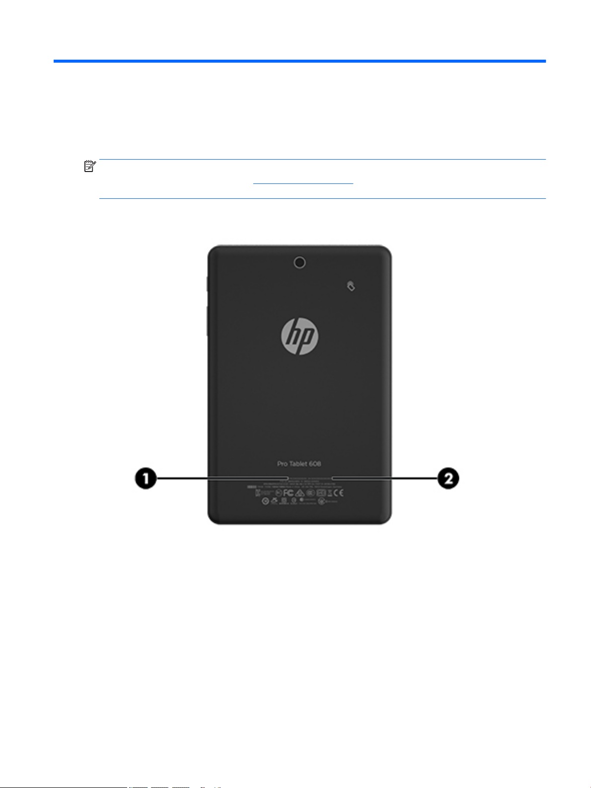
3 Illustrated parts catalog
Locating the serial number and model number
NOTE: HP continually improves and changes product parts. For complete and current information on
supported parts for your tablet, go to http://partsurfer.hp.com, select your country or region, and then follow
the on-screen instructions.
The model number (1) and serial number (2) of your tablet are located on the back cover of the tablet. You
may need the information when you travel internationally or when you contact support.
Locating the serial number and model number 7
Page 14
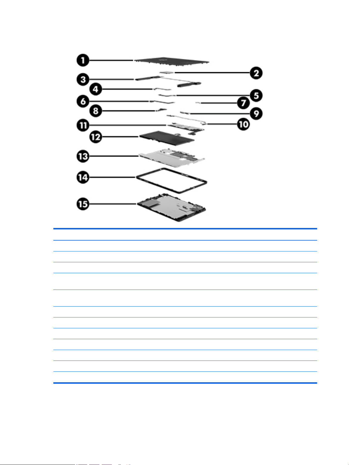
Tablet major components
Item Component Spare part number
(1) Back cover 823034-001
(2) WWAN module
(3) Speaker kit (includes left and right speakers and cables) 823050-001
(4) Front-facing webcamera (includes cable) 823055-001
(5) Rear-facing webcamera (includes cable) 823056-001
(6) Vibration motor board 823042-001
(7) Audio/USB connector board (spared with the system board)
(8) POGO pin connector and cable 823960-001
(9) Antenna kit, includes all WLAN, WWAN, and Proximity Sensor antennas 823033-001
●
HP It4211, LTE/EV-D0/HSPA+, QCOM MDM9615 Integrated GPS 793116-005
●
Huawei ME906E, LTE/HSPA+, QCOM MDM9215, integrated GPS: HP lt4112 LTE/HSPA+
Gobi 4G Module
●
Huawei MU736, HSPA+, Intel XMM6260 3G, integrated GPS: HP hs3110 HSPA+ Mobile
Broadband Module
790198-005
793516-005
8 Chapter 3 Illustrated parts catalog
Page 15

Item Component Spare part number
(10) System board, includes audio board and thermal pads
(11) Battery and middle plate, 21 Whr, 1S2P, Lithium-polymer, non-user removable
●
Equipped with Windows 10, Intel Atom x5-Z8500 Quad Core 2 GB RAM memory, 32 GB
eMMC, NFC (WLAN soldered on)
●
Equipped with Windows 10, Intel Atom x5-Z8500 Quad Core 2 GB RAM memory, 64 GB
eMMC, NFC (WLAN soldered on)
●
Equipped with Windows 10, Intel Atom x5-Z8500 Quad Core 4 GB RAM memory, 64 GB
eMMC NFC, WWAN support (WLAN soldered on)
●
Equipped with Windows 10, Intel Atom x5-Z8500 Quad Core 4 GB RAM memory, 64 GB
eMMC NFC, (WLAN soldered on)
●
Equipped with Windows 10, Intel Atom x5-Z8500 Quad Core 4 GB RAM memory, 128
GB eMMC NFC, WWAN support (WLAN soldered on)
●
Equipped with Windows 8.1, Intel Atom x5-Z8500 Quad Core 2 GB RAM memory, 32 GB
eMMC, NFC (WLAN soldered on)
●
Equipped with Windows 8.1, Intel Atom x5-Z8500 Quad Core 2 GB RAM memory, 64 GB
eMMC, NFC (WLAN soldered on)
●
Equipped with Windows 8.1, Intel Atom x5-Z8500 Quad Core 4 GB RAM memory, 64 GB
eMMC NFC, WWAN support (WLAN soldered on)
●
Equipped with Windows 8.1, Intel Atom x5-Z8500 Quad Core 4 GB RAM memory, 64 GB
eMMC NFC, (WLAN soldered on)
●
Equipped with Windows 8.1, Intel Atom x5-Z8500 Quad Core 4 GB RAM memory, 128
GB eMMC NFC, WWAN support (WLAN soldered on)
823051-601
823052-601
823053-601
826801-601
823054-601
823051-401
823052-401
823053-401
826801-401
823054-401
(12) LCD metal outer ring
For models with WWAN capability 823038-001
For models without WWAN capability 823037-001
(13) 7.86 inch QXGA (2048x1536) BV WLED UWVA 70%cg 450nits MIPI Touchscreen display
●
For models with WWAN capability 823040-001
●
For models without WWAN capability 823039-001
panel assembly, includes bezel and touchscreen LCD module
Miscellaneous parts
Component Spare part number
15W + Type C charging Micro USB Adapter (100% attached) 792619-001
Cable kit, includes audio board cables and DMIC cables 823035-001
Metal kit, includes SD and SIM card trays, LCD sheet, battery sheet, audio jack bracket, and POGO pin
bracket
Pen 823045-001
Plastics kit, includes power button and volume button 823046-001
823047-001
823036-001
Miscellaneous parts 9
Page 16

Component Spare part number
Power cord with adapter
●
For use in Australia 762584-005
●
For use in Europe 762584-004
●
For use in India 762584-006
●
For use in North America 762584-001
●
For use in the United Kingdom 762584-003
Rubber kit, includes microphone rubber, WWAN gasket, camera foils, and plastic 823048-001
Screw kit 823049-001
Tablet
●
For use in Asia, supports SKU# N4L91PA-ABG 833756-001
●
For use in Asia, supports SKU# N4L92PA-ABG 833757-001
●
For use in Asia, supports SKU# N4L93PA-ABG 833758-001
●
For use in North America, supports SKU# N3G36AA-ABA 833759-001
●
For use in North America, supports SKU# N3G41AA-ABA 833760-001
●
For use in North America, supports SKU# N3G38AA-ABA 833761-001
●
For use in North America, supports SKU# N3G33AA-ABA 833762-001
●
For use in North America, supports SKU# N3G40AA-ABA 833763-001
Sequential part number listing
Spare part number Description
762584-001 Power cord with adapter, for use in North America
762584-003 Power cord with adapter, for use in the United Kingdom
762584-004 Power cord with adapter, for use in Europe
762584-005 Power cord with adapter, for use in Australia
762584-006 Power cord with adapter, for use in India
790198-005 WWAN module, Huawei ME906E, LTE/HSPA+, QCOM MDM9215, integrated GPS: HP lt4112 LTE/HSPA+ Gobi
4G Module
792619-001 15W + Type C charging micro USB adapter (100% attached)
793116-005 WWAN module, HP It4211, LTE/EV-D0/HSPA+, QCOM MDM9615 Integrated GPS
793516-005 WWAN module, Huawei MU736, HSPA+, Intel XMM6260 3G, integrated GPS: HP hs3110 HSPA+ Mobile
Broadband Module
823033-001 Antenna kit, includes all WLAN, WWAN, and Proximity Sensor antennas
823034-001 Back cover
823035-001 Cable kit, includes audio board and DMIC cables
10 Chapter 3 Illustrated parts catalog
Page 17

Spare part number Description
823036-001 Metal kit, includes SD and SIM card trays, LCD sheet, battery sheet, audio jack bracket, and POGO pin
bracket
823037-001 Outer ring for models without WWAN capability
823038-001 Outer ring for models with WWAN capability
823039-001 Battery and middle plate for models without WWAN capability, 21 Whr, 1S2P, Lithium-polymer, non-user
removable
823040-001 Battery and middle plate for models with WWAN capability, 21 Whr, 1S2P, Lithium-polymer, non-user
removable
823042-001 Vibration motor board
823045-001 Pen
823046-001 Plastics kit, includes power button and volume button
823047-001 7.86 inch QXGA (2048x1536) BV WLED UWVA 70%cg 450nits MIPI Touchscreen display panel assembly
823048-001 Rubber kit, includes microphone rubber, WWAN gasket, camera foils, and plastic
823049-001 Screw kit
823050-001 Speaker kit (includes left and right speakers and cables)
823051-401 System board equipped with Windows 8.1, Intel Atom x5-Z8500 Quad Core 2 GB RAM memory, 32 GB
eMMC, NFC (WLAN soldered on), includes thermal pads and audio board
823051-601 System board equipped with Windows 10, Intel Atom x5-Z8500 Quad Core 2 GB RAM memory, 32 GB
eMMC, NFC (WLAN soldered on), includes thermal pads and audio board
823052-401 System board equipped with Windows 8.1, Intel Atom x5-Z8500 Quad Core 2 GB RAM memory, 64 GB
eMMC NFC (WLAN soldered on), includes thermal pads and audio board
823052-601 System board equipped with Windows 10, Intel Atom x5-Z8500 Quad Core 2 GB RAM memory, 64 GB
eMMC NFC (WLAN soldered on), includes thermal pads and audio board
823053-401 System board equipped with Windows 8.1, Intel Atom x5-Z8500 Quad Core 4 GB RAM memory, 64 GB
eMMC NFC, WWAN support (WLAN soldered on), includes thermal pads and audio board
823053-601 System board equipped with Windows 10, Intel Atom x5-Z8500 Quad Core 4 GB RAM memory, 64 GB
eMMC NFC, WWAN support (WLAN soldered on), includes thermal pads and audio board
823054-401 System board equipped with Windows 8.1, Intel Atom x5-Z8500 Quad Core 4 GB RAM memory, 128 GB
eMMC NFC, WWAN support (WLAN soldered on), includes thermal pads and audio board
823054-601 System board equipped with Windows 10, Intel Atom x5-Z8500 Quad Core 4 GB RAM memory, 128 GB
eMMC NFC, WWAN support (WLAN soldered on), includes thermal pads and audio board
823055-001 Front-facing webcamera (includes cable)
823056-001 Rear-facing webcamera (includes cable)
823960-001 POGO pin connector and cable
826801-401 System board equipped with Windows 8.1, Intel Atom x5-Z8500 Quad Core 4 GB RAM memory, 64 GB
eMMC NFC (WLAN soldered on), includes thermal pads and audio board
826801-601 System board equipped with Windows 10, Intel Atom x5-Z8500 Quad Core 4 GB RAM memory, 64 GB
eMMC NFC (WLAN soldered on), includes thermal pads and audio board
833756-001 Tablet for use in Asia, supports SKU# N4L91PA-ABG
833757-001 Tablet for use in Asia, supports SKU# N4L92PA-ABG
Sequential part number listing 11
Page 18

Spare part number Description
833758-001 Tablet for use in Asia, supports SKU# N4L93PA-ABG
833759-001 Tablet for use in North America, supports SKU# N3G36AA-ABA
833760-001 Tablet for use in North America, supports SKU# N3G41AA-ABA
833761-001 Tablet for use in North America, supports SKU# N3G38AA-ABA
833762-001 Tablet for use in North America, supports SKU# N3G33AA-ABA
833763-001 Tablet for use in North America, supports SKU# N3G40AA-ABA
12 Chapter 3 Illustrated parts catalog
Page 19

4 Removal and replacement preliminary
requirements
Tools required
You will need the following tools to complete the removal and replacement procedures:
●
Magnetic screw driver
●
Phillips 00 screw driver
●
Phillips 000 screw driver
●
Plastic pry tool
●
Suction cup
●
Tweezers
Service considerations
The following sections include some of the considerations that you must keep in mind during disassembly
and assembly procedures.
NOTE: As you remove each subassembly from the tablet, place the subassembly (and all accompanying
screws) away from the work area to prevent damage.
Plastic parts
CAUTION: Using excessive force during disassembly and reassembly can damage plastic parts. Use care
when handling the plastic parts. Apply pressure only at the points designated in the maintenance
instructions.
Cables and connectors
CAUTION: When servicing the tablet, be sure that cables are placed in their proper locations during the
reassembly process. Improper cable placement can damage the tablet.
Cables must be handled with extreme care to avoid damage. Apply only the tension required to unseat or seat
the cables during removal and insertion. Handle cables by the connector whenever possible. In all cases, avoid
bending, twisting, or tearing cables. Be sure that cables are routed in such a way that they cannot be caught
or snagged by parts being removed or replaced. Handle ex cables with extreme care; these cables tear
easily.
Tools required 13
Page 20

Grounding guidelines
Electrostatic discharge damage
Electronic components are sensitive to electrostatic discharge (ESD). Circuitry design and structure determine
the degree of sensitivity. Networks built into many integrated circuits provide some protection, but in many
cases, ESD contains enough power to alter device parameters or melt silicon junctions.
A discharge of static electricity from a nger or other conductor can destroy static-sensitive devices or
microcircuitry. Even if the spark is neither felt nor heard, damage may have occurred.
An electronic device exposed to ESD may not be aected at all and can work perfectly throughout a normal
cycle. Or the device may function normally for a while, then degrade in the internal layers, reducing its life
expectancy.
CAUTION: To prevent damage to the tablet when you are removing or installing internal components,
observe these precautions:
Keep components in their electrostatic-safe containers until you are ready to install them.
Before touching an electronic component, discharge static electricity by using the guidelines described in this
section.
Avoid touching pins, leads, and circuitry. Handle electronic components as little as possible.
If you remove a component, place it in an electrostatic-safe container.
The following table shows how humidity aects the electrostatic voltage levels generated by
dierent activities.
CAUTION: A product can be degraded by as little as 700 V.
Typical electrostatic voltage levels
Relative humidity
Event 10% 40% 55%
Walking across carpet 35,000 V 15,000 V 7,500 V
Walking across vinyl oor 12,000 V 5,000 V 3,000 V
Motions of bench worker 6,000 V 800 V 400 V
Removing DIPS from plastic tube 2,000 V 700 V 400 V
Removing DIPS from vinyl tray 11,500 V 4,000 V 2,000 V
Removing DIPS from Styrofoam 14,500 V 5,000 V 3,500 V
Removing bubble pack from PCB 26,500 V 20,000 V 7,000 V
Packing PCBs in foam-lined box 21,000 V 11,000 V 5,000 V
14 Chapter 4 Removal and replacement preliminary requirements
Page 21

Packaging and transporting guidelines
Follow these grounding guidelines when packaging and transporting equipment:
●
To avoid hand contact, transport products in static-safe tubes, bags, or boxes.
●
Protect ESD-sensitive parts and assemblies with conductive or approved containers or packaging.
●
Keep ESD-sensitive parts in their containers until the parts arrive at static-free workstations.
●
Place items on a grounded surface before removing items from their containers.
●
Always be properly grounded when touching a component or assembly.
●
Store reusable ESD-sensitive parts from assemblies in protective packaging or nonconductive foam.
●
Use transporters and conveyors made of antistatic belts and roller bushings. Be sure that mechanized
equipment used for moving materials is wired to ground and that proper materials are selected to avoid
static charging. When grounding is not possible, use an ionizer to dissipate electric charges.
Workstation guidelines
Follow these grounding workstation guidelines:
●
Cover the workstation with approved static-shielding material.
●
Use a wrist strap connected to a properly grounded work surface and use properly grounded tools and
equipment.
●
Use conductive eld service tools, such as cutters, screw drivers, and vacuums.
●
When xtures must directly contact dissipative surfaces, use xtures made only of static-safe materials.
●
Keep the work area free of nonconductive materials, such as ordinary plastic assembly aids
and Styrofoam.
●
Handle ESD-sensitive components, parts, and assemblies by the case or PCM laminate. Handle these
items only at static-free workstations.
●
Avoid contact with pins, leads, or circuitry.
●
Turn o power and input signals before inserting or removing connectors or test equipment.
Grounding guidelines 15
Page 22

Equipment guidelines
Grounding equipment must include either a wrist strap or a foot strap at a grounded workstation.
●
When seated, wear a wrist strap connected to a grounded system. Wrist straps are exible straps with a
minimum of one megohm ±10% resistance in the ground cords. To provide proper ground, wear a strap
snugly against the skin at all times. On grounded mats with banana-plug connectors, use alligator clips
to connect a wrist strap.
●
When standing, use foot straps and a grounded oor mat. Foot straps (heel, toe, or boot straps) can be
used at standing workstations and are compatible with most types of shoes or boots. On conductive
oors or dissipative oor mats, use foot straps on both feet with a minimum of one megohm resistance
between the operator and ground. To be
The following grounding equipment is recommended to prevent electrostatic damage:
●
Antistatic tape
●
Antistatic smocks, aprons, and sleeve protectors
●
Conductive bins and other assembly or soldering aids
●
Nonconductive foam
●
Conductive tabletop workstations with ground cords of one megohm resistance
●
Static-dissipative tables or oor mats with hard ties to the ground
●
Field service kits
eective, the conductive must be worn in contact with the skin.
●
Static awareness labels
●
Material-handling packages
●
Nonconductive plastic bags, tubes, or boxes
●
Metal tote boxes
●
Electrostatic voltage levels and protective materials
The following table lists the shielding protection provided by antistatic bags and oor mats.
Material Use Voltage protection level
Antistatic plastics Bags 1,500 V
Carbon-loaded plastic Floor mats 7,500 V
Metallized laminate Floor mats 5,000 V
16 Chapter 4 Removal and replacement preliminary requirements
Page 23

5 Removal and replacement procedures
Tablet component replacement procedures
CAUTION: Tablet components described in this chapter should only be accessed by an authorized service
provider. Accessing these parts can damage the tablet and void the warranty.
NOTE: HP continually improves and changes product parts. For complete and current information on
supported parts for your tablet, go to http://partsurfer.hp.com, select your country or region, and then follow
the on-screen instructions.
This chapter provides removal and replacement procedures for authorized service provider only parts.
There are as many as 30 screws that must be removed, replaced, and/or loosened when servicing the tablet.
Make special note of each screw size and location during removal and replacement.
MicroSD card tray
CAUTION: To reduce the risk of loss of data or an unresponsive system, use the following procedure to
safely remove the microSD card.
NOTE: The microSD card tray is spared as part of the metal kit, spare part number 823036-001.
Remove the microSD card tray:
1. Save your information and close all programs associated with the microSD card.
2. Click the remove hardware icon on the Windows desktop in the notication area, at the far right of the
taskbar. Then follow the on-screen instructions.
3. Insert a small straightened paper clip (1) into the card tray access hole.
4. Press in gently only until the card tray is ejected.
5. Remove the tray (2) from the tablet.
Reverse the steps to replace the tray.
Tablet component replacement procedures 17
Page 24

Nano SIM card tray (select models only)
NOTE: The nano SIM card tray is spared as part of the metal kit, spare part number 823036-001.
Remove the SIM card tray:
1. Insert a small straightened paper clip (1) into the card tray access hole.
2. Press in gently only until the card tray is ejected.
3. Remove the tray (2) from the tablet.
Reverse the steps to replace the tray.
Back cover
Description Spare part number
Back cover 823034-001
Before disassembling the tablet, follow these steps:
1. Turn o the tablet. If you are unsure whether the tablet is o, turn the tablet on, and then shut it down
through the operating system.
2. Disconnect the power from the tablet by unplugging the power adapter cord from the tablet.
3. Disconnect all external devices from the tablet.
Remove the back cover:
CAUTION: Before turning the display panel assembly upside down, make sure the work surface is clear of
tools, screws, and any other foreign objects. Failure to follow this caution can result in damage to the display
panel assembly.
1. Place the tablet on a at surface, display panel side down.
2. Place a suction tool (1) on the back cover near the POGO connector.
18 Chapter 5 Removal and replacement procedures
Page 25

3. Lift the tool handle (2) and the use the handle (3) to remove the back cover.
Reverse this procedure to install the back cover.
Disconnecting the battery
CAUTION: Disconnecting a battery that is the sole power source for the tablet can cause loss of information.
To prevent loss of information, save your work or shut down the tablet through the operating system before
disconnecting the battery.
Before disconnecting the battery, follow these steps:
1. Turn o the computer. If you are unsure whether the computer is o, turn the computer on, and then
shut it down through the operating system.
2. Disconnect the power from the computer by unplugging the power cord from the computer.
3. Disconnect all external devices from the computer.
4. Remove the bottom cover (see Back cover on page 18).
NOTE: Disconnect the battery cable carefully; pulling too hard can break the system board connector.
Disconnect the battery:
Disconnecting the battery 19
Page 26

1. Remove the 1.2 mm P0 Phillips-head screw (1) that secures the battery connector bracket to the system
board.
2. Lift the battery connector (2) to remove it from the system board.
3. Carefully remove the battery ribbon cable (3) from the adhesive that secures it to the system board, and
then disconnect the battery from the system board.
Reverse this procedure to connect the battery.
20 Chapter 5 Removal and replacement procedures
Page 27

WWAN module (select models only)
Description Spare part number
HP It4211, LTE/EV-D0/HSPA+, QCOM MDM9615 Integrated GPS 793116-005
Huawei ME906E, LTE/HSPA+, QCOM MDM9215, integrated GPS: HP lt4112 LTE/HSPA+ Gobi 4G Module 790198-005
Huawei MU736, HSPA+, Intel XMM6260 3G, integrated GPS: HP hs3110 HSPA+ Mobile Broadband Module 793516-005
Before removing the WWAN module, follow these steps:
1. Turn o the computer. If you are unsure whether the computer is o, turn the computer on, and then
shut it down through the operating system.
2. Disconnect the power from the computer by unplugging the power cord from the computer.
3. Disconnect all external devices from the computer.
4. Remove the bottom cover (see Back cover on page 18).
5. Disconnect the battery (see Disconnecting the battery on page 19).
Remove the WWAN module:
1. Disconnect the WWAN antenna cables (1) from the terminals on the WWAN module.
NOTE: The red WWAN antenna cable is connected to the WWAN module “Main” terminal. The blue
WWAN antenna cable is connected to the WWAN module “Aux” terminal.
2. Remove the 2 mm P0 Phillips screw (2) that secures the WWAN module to the system board.
WWAN module (select models only) 21
Page 28

3. Remove the WWAN module (3) by pulling the module away from the slot.
NOTE: WWAN modules are designed with a notch to prevent incorrect insertion.
NOTE: If the WWAN antennas are not connected to the terminals on the WWAN module, the protective
sleeves must be installed on the antenna connectors, as shown in the following illustration.
Reverse this procedure to install the WWAN module.
22 Chapter 5 Removal and replacement procedures
Page 29

Left speaker
Description Spare part number
Speaker kit (includes left and right speakers and cables) 823050-001
Before removing the speakers, follow these steps:
1. Turn o the tablet. If you are unsure whether the tablet is o, turn the tablet on, and then shut it down
through the operating system.
2. Disconnect the power from the tablet by unplugging the power adapter cord from the tablet.
3. Disconnect all external devices from the tablet.
4. Remove the back cover (see Back cover on page 18).
5. Disconnect the battery (see Disconnecting the battery on page 19).
6. Disconnect the WWAN antenna (see WWAN module (select models only) on page 21).
Remove the left speaker:
1. Disconnect the left speaker cable (1) from the system board .
2. Remove the two 3 mm P0 Phillips screws (2) that secure the left speaker to the display panel assembly.
3. Lift and remove the left speaker (3).
Reverse this procedure to install the left speaker.
Left speaker 23
Page 30

Audio board
IMPORTANT: The audio board is spared with the system board. You must replace the system board when
you replace the audio board. See System board on page 30.
The BIOS on the tablet is injected into the audio board. If you replace the audio board, but not the system
board, you must reash the Trusted Execution Environment (TXE) region in SPI ROM to avoid a TXE encryption
key mismatch between the audio board and the system board.
Before removing the audio board, follow these steps:
1. Turn o the tablet. If you are unsure whether the tablet is o, turn the tablet on, and then shut it down
through the operating system.
2. Disconnect the power from the tablet by unplugging the power adapter cord from the tablet.
3. Disconnect all external devices from the tablet.
4. Remove the back cover (see Back cover on page 18).
5. Disconnect the battery (see Disconnecting the battery on page 19).
6. Remove the WWAN module (see WWAN module (select models only) on page 21).
7. Remove the left speaker (see Left speaker on page 23).
Remove the audio board:
CAUTION: Use care to prevent damaging the ZIF connectors and ribbon cables.
IMPORTANT: Make careful note of the placement of the proximity sensor antenna for later replacement.
1. Release the proximity antenna ZIF connector (1), and then disconnect the proximity sensor antenna
ribbon cable from the audio board.
2. Release the audio board ZIF connector (2), and then disconnect the audio board ribbon cable from the
audio board.
3. Remove the two 3 mm P0 Phillips screws (3) that secure the audio board bracket to the display panel
assembly, and then remove the bracket.
24 Chapter 5 Removal and replacement procedures
Page 31

4. Lift and remove the audio board (4).
Reverse this procedure to install the audio board.
Audio board 25
Page 32

Vibration motor board
Description Spare part number
Vibration motor board 823042-001
Before removing the vibration motor board, follow these steps:
1. Turn o the tablet. If you are unsure whether the tablet is o, turn the tablet on, and then shut it down
through the operating system.
2. Disconnect the power from the tablet by unplugging the power adapter cord from the tablet.
3. Disconnect all external devices from the tablet.
4. Remove the back cover (see Back cover on page 18).
5. Disconnect the battery (see Disconnecting the battery on page 19).
Remove the vibration motor board:
1. Lift up the vibration motor board, and then disconnect the cable connector (1) from the system board.
2. Remove the vibrator motor cable from the routing tab on the right speaker, and then remove the
vibration motor board (2).
Reverse this procedure to install the vibration motor board.
26 Chapter 5 Removal and replacement procedures
Page 33

Front-facing webcamera
Description Spare part number
Front-facing webcamera (includes cable) 823055-001
Before removing the front-facing webcamera, follow these steps:
1. Turn o the tablet. If you are unsure whether the tablet is o, turn the tablet on, and then shut it down
through the operating system.
2. Disconnect the power from the tablet by unplugging the power adapter cord from the tablet.
3. Disconnect all external devices from the tablet.
4. Remove the back cover (see Back cover on page 18).
5. Disconnect the battery (see Disconnecting the battery on page 19).
6. Remove the left speaker (see Left speaker on page 23).
7. Disconnect the proximity sensor antenna ribbon cable from the audio board (see Audio board
on page 24).
Remove the front-facing webcamera:
CAUTION: Use care to prevent damaging the ZIF connectors and ribbon cables.
1. Release the copper grounding strap and remove the plastic tape (1) covering the front-facing
webcamera ZIF connector.
2. Release the ZIF connector (2) attaching the front-facing webcamera cable to the system board.
3. Peel up the adhesive connecting the webcamera cable to the battery. Start from the elbow of the
adhesive and lift the front-facing webcamera cable (3) from the display panel assembly.
IMPORTANT: The webcamera is held in place by two plastic retaining clips. Detach the camera
carefully to avoid breaking the clips.
Front-facing webcamera 27
Page 34

4. Carefully remove the front-facing webcamera (4) from the retention clips that secure it to the display
panel assembly, and then remove the webcamera.
Reverse this procedure to install the front-facing webcamera.
Rear-facing webcamera
Description Spare part number
Rear-facing webcamera (includes cable) 823056-001
Before removing the rear-facing webcamera, follow these steps:
1. Turn o the tablet. If you are unsure whether the tablet is o, turn the tablet on, and then shut it down
through the operating system.
2. Disconnect the power from the tablet by unplugging the power adapter cord from the tablet.
3. Disconnect all external devices from the tablet.
4. Remove the back cover (see Back cover on page 18).
5. Disconnect the battery (see Disconnecting the battery on page 19).
6. Remove the left speaker (see Left speaker on page 23).
7. Disconnect the proximity sensor antenna ribbon cable from the audio board (see Audio board
on page 24).
Remove the rear-facing webcamera:
28 Chapter 5 Removal and replacement procedures
Page 35

CAUTION: Use care to prevent damaging the ZIF connectors and ribbon cables.
1. Release the copper grounding strap and remove the plastic tape (1) covering the rear-facing webcamera
ZIF connector.
2. Release the ZIF connector (2) attaching the rear-facing webcamera cable to the system board.
3. Peel up the adhesive connecting the webcamera cable to the battery. Start from the elbow of the
adhesive and lift the rear-facing webcamera cable (3) from the system board.
4. Route the camera cable through the antenna proximity sensor area (4).
5. Remove the rear-facing webcamera (5) from the display panel assembly.
Reverse this procedure to install the rear-facing webcamera.
IMPORTANT: Ensure that the ring gasket is properly positioned in the rear-facing webcam cradle before
replacing the rear-facing camera.
Rear-facing webcamera 29
Page 36

System board
Description Spare part number
Equipped with Windows 10, Intel Atom x5-Z8500 Quad Core 2 GB RAM memory, 32 GB eMMC, NFC (WLAN
soldered on), includes thermal pads and audio board
Equipped with Windows 10, Intel Atom x5-Z8500 Quad Core 2 GB RAM memory, 64 GB eMMC, NFC (WLAN
soldered on), includes thermal pads and audio board
Equipped with Windows 10, Intel Atom x5-Z8500 Quad Core 4 GB RAM memory, 64 GB eMMC NFC, WWAN
support (WLAN soldered on), includes thermal pads and audio board
Equipped with Windows 10, Intel Atom x5-Z8500 Quad Core 4 GB RAM memory, 64 GB eMMC NFC (WLAN
soldered on), includes thermal pads and audio board
Equipped with Windows 10, Intel Atom x5-Z8500 Quad Core 4 GB RAM memory, 128 GB eMMC NFC,
WWAN support (WLAN soldered on), includes thermal pads and audio board
Equipped with Windows 8.1, Intel Atom x5-Z8500 Quad Core 2 GB RAM memory, 32 GB eMMC, NFC
(WLAN soldered on), includes thermal pads and audio board
Equipped with Windows 8.1, Intel Atom x5-Z8500 Quad Core 2 GB RAM memory, 64 GB eMMC, NFC
(WLAN soldered on), includes thermal pads and audio board
Equipped with Windows 8.1, Intel Atom x5-Z8500 Quad Core 4 GB RAM memory, 64 GB eMMC NFC,
WWAN support (WLAN soldered on), includes thermal pads and audio board
Equipped with Windows 8.1, Intel Atom x5-Z8500 Quad Core 4 GB RAM memory, 64 GB eMMC NFC (WLAN
soldered on), includes thermal pads and audio board
Equipped with Windows 8.1, Intel Atom x5-Z8500 Quad Core 4 GB RAM memory, 128 GB eMMC NFC,
WWAN support (WLAN soldered on), includes thermal pads and audio board
823051-601
823052-601
823053-601
826801-601
823054-601
823051-401
823052-401
823053-401
826801-401
823054-401
IMPORTANT: The processor, memory, WLAN+Bluetooth, and eMMC storage card are all embedded on the
system board. If any of these components fail and require replacement, the entire system board must be
replaced. The tablet provides units with 32G, 64GB, and 128GB eMMC modules soldered onto the system
board. In addition, the system board contains the Windows DPK. If you are replacing the system board, be
sure to order the board that contains the correct storage capacity and Windows OS version.
IMPORTANT: Select tablet models are congured with an Intel® AtomTM series processor and a Windows®
operating system. If your tablet is congured as described, do not change the processor conguration
setting in mscong.exe from 4 or 2 processors to 1 processor. If you do so, your tablet will not restart. You
will have to perform a factory reset to restore the original settings.
IMPORTANT: The audio board is paired with the system board. The audio board must be replaced every time
the system board is replaced and is provided in the system board spare kit. When the audio board and system
board are replaced together, reashing of the TXE region in SPI ROM is not necessary.
The system boards are not localized; if the system board is replaced, the operating system must also be
reinstalled.
IMPORTANT: After system board replacement, be sure to complete postinstallation tasks as required that
may include:
●
Verifying functionality of the tablet
●
Updating the BIOS
●
Updating DMI and other settings
●
Injecting Windows Digital Product Keys
30 Chapter 5 Removal and replacement procedures
Page 37

Before removing the system board, follow these steps:
1. Turn o the tablet. If you are unsure whether the tablet is o, turn the tablet on, and then shut it down
through the operating system.
2. Disconnect the power from the tablet by unplugging the power adapter cord from the tablet.
3. Disconnect all external devices from the tablet.
4. Remove the MicroSD card tray (see MicroSD card tray on page 17).
5. Remove the Nano SIM card tray (select products only) (see Nano SIM card tray (select models only)
on page 18.
6. Remove the back cover (see Back cover on page 18).
7. Disconnect the battery (see Disconnecting the battery on page 19).
8. Remove the WWAN module (see WWAN module (select models only) on page 21).
9. Remove the left speaker (see Left speaker on page 23).
10. Remove the audio board (see Audio board on page 24).
11. Remove the vibration motor board (see Vibration motor board on page 26).
12. Remove the front-facing webcamera (see Front-facing webcamera on page 27).
13. Remove the rear-facing webcamera (see Rear-facing webcamera on page 28).
Remove the system board:
1. Remove the screw (1) that connects the touch module to the system board, and then lift up the touch
module (2) to move it out of the way.
2. Remove the two 1.2 mm P0 Phillips screws that secure the POGO pin metal bracket to the system board
and the two 1.2 mm P0 Phillips-head screws that secure the display panel cable bracket, and then
remove the brackets (1).
System board 31
Page 38

3. Disconnect the POGO pin connector (2) from the system board and disconnect the microphone ribbon
cable, and disconnect the right speaker cable (3) and move the cables out of the way.
32 Chapter 5 Removal and replacement procedures
Page 39

4. Carefully disconnect the wireless LAN antenna cables (1) from the system board, Remove the MAIN
wireless LAN antenna cable from the routing clips on the system board and remove the cable (2).
5. Remove the ve Phillips silver screws (1) securing the system board to the display panel assembly.
System board 33
Page 40

6. Carefully lift the left edge of the system board and at an angle, remove the USB port from the cutout in
the display panel assembly. and then remove the system board (2).
7. Turn over the system board, and then release the ZIF connector to remove the audio cable (1) from the
system board.
Reverse this procedure to install the system board.
34 Chapter 5 Removal and replacement procedures
Page 41

Right speaker
Description Spare part number
Speaker kit (includes left and right speakers and cables) 823050-001
Before removing the right speaker, follow these steps:
1. Turn o the tablet. If you are unsure whether the tablet is o, turn the tablet on, and then shut it down
through the operating system.
2. Disconnect the power from the tablet by unplugging the power adapter cord from the tablet.
3. Disconnect all external devices from the tablet.
4. Remove the MicroSD card tray (see MicroSD card tray on page 17).
5. Remove the Nano SIM card tray (select products only) (see Nano SIM card tray (select models only)
on page 18.
6. Remove the back cover (see Back cover on page 18).
7. Disconnect the battery (see Disconnecting the battery on page 19).
8. Remove the WWAN module (see WWAN module (select models only) on page 21).
9. Remove the left speaker (see Left speaker on page 23).
10. Remove the audio board (see Audio board on page 24).
11. Remove the vibration motor board (see Vibration motor board on page 26).
12. Remove the front-facing webcamera (see Front-facing webcamera on page 27).
13. Remove the rear-facing webcamera (see Rear-facing webcamera on page 28).
14. Remove the system board (see System board on page 30).
Remove the right speaker:
1. Remove the 3 mm P0 Phillips screw (1) that secures the right speaker to the display panel assembly.
Right speaker 35
Page 42

2. Lift and remove the right speaker (2).
Reverse this procedure to install the right speaker.
Battery and middle plate
Description Spare part number
Battery and middle plate for models without WWAN capability, 21 Whr, 1S2P, Lithium-polymer, non-
user removable
Battery and middle plate for models with WWAN capability, 21 Whr, 1S2P, Lithium-polymer, non-user
removable
Before removing the battery, follow these steps:
1. Turn o the tablet. If you are unsure whether the tablet is o, turn the tablet on, and then shut it down
through the operating system.
2. Disconnect the power from the tablet by unplugging the power adapter cord from the tablet.
3. Disconnect all external devices from the tablet.
4. Remove the MicroSD card tray (see MicroSD card tray on page 17).
5. Remove the Nano SIM card tray (select products only) (see Nano SIM card tray (select models only)
on page 18.
823039-001
823040-001
6. Remove the back cover (see Back cover on page 18).
7. Disconnect the battery (see Disconnecting the battery on page 19).
36 Chapter 5 Removal and replacement procedures
Page 43

8. Remove the WWAN module (see WWAN module (select models only) on page 21).
9. Remove the left speaker (see Left speaker on page 23).
10. Remove the audio board (see Audio board on page 24).
11. Remove the vibration motor board (see Vibration motor board on page 26).
12. Remove the front-facing webcamera (see Front-facing webcamera on page 27).
13. Remove the rear-facing webcamera (see Rear-facing webcamera on page 28).
14. Remove the system board (see System board on page 30).
15. Remove the right speaker (see Right speaker on page 35).
WARNING! To reduce potential safety issues, use only the battery provided with the tablet, a replacement
battery provided by HP, or a compatible battery purchased from HP.
WARNING! Do not remove the battery from the middle plate. To avoid personal injury and damage to the
product, use extreme care not to puncture, twist, or crack the battery. A puncture or rupture of the battery
internally can cause a short with the battery bursting into ames.
CAUTION: Removing a battery that is the sole power source for the tablet can cause loss of information. To
prevent loss of information, save your work or shut down the tablet through the operating system before
disconnecting and removing the battery.
Remove the battery and middle plate:
1. Peel o and remove the proximity sensor plastic (1).
2. Remove the six 2 mm P0 Phillips and two 3 mm P0 Phillips screws (1) that secure the middle frame to
the display assembly.
Battery and middle plate 37
Page 44

3. Lift and remove the battery and middle plate (2).
Reverse this procedure to install the battery and middle plate.
Outer ring
Description Spare part number
Outer ring for models with WWAN capability 823038-001
Outer ring for models without WWAN capability 823037-001
1. Turn o the tablet. If you are unsure whether the tablet is o, turn the tablet on, and then shut it down
through the operating system.
2. Disconnect all external devices from the tablet.
3. Remove the MicroSD card tray (see MicroSD card tray on page 17).
4. Remove the Nano SIM card tray (select products only) (see Nano SIM card tray (select models only)
on page 18.
5. Remove the back cover (see Back cover on page 18).
6. Disconnect the battery (see Disconnecting the battery on page 19).
7. Remove the WWAN module (see WWAN module (select models only) on page 21).
8. Remove the left speaker (see Left speaker on page 23).
9. Remove the audio board (see Audio board on page 24).
38 Chapter 5 Removal and replacement procedures
Page 45

10. Remove the vibration motor board (see Vibration motor board on page 26).
11. Remove the front-facing webcamera (see Front-facing webcamera on page 27).
12. Remove the rear-facing webcamera (see Rear-facing webcamera on page 28).
13. Remove the system board (see System board on page 30).
14. Remove the right speaker (see Right speaker on page 35).
15. Remove the battery and middle plate (see Battery and middle plate on page 36).
Remove the outer ring:
1. Remove the power and volume buttons from the ring, and then remove the two 2 mm P0 Phillips screws
(1) that secure the outer ring to the display panel assembly.
2. Disconnect the outer ring from the clips (2) on the frame, and then lift the outer ring from the display
assembly.
Reverse this procedure to install the outer ring.
Outer ring 39
Page 46

POGO pin connector
Description Spare part number
POGO pin connector and cable 823960-001
1. Turn o the tablet. If you are unsure whether the tablet is o, turn the tablet on, and then shut it down
through the operating system.
2. Disconnect the power from the tablet by unplugging the power adapter cord from the tablet.
3. Disconnect all external devices from the tablet.
4. Remove the MicroSD card tray (see MicroSD card tray on page 17).
5. Remove the Nano SIM card tray (select products only) (see Nano SIM card tray (select models only)
on page 18.
6. Remove the back cover (see Back cover on page 18).
7. Disconnect the battery (see Disconnecting the battery on page 19).
8. Remove the WWAN module (see WWAN module (select models only) on page 21).
9. Remove the left speaker (see Left speaker on page 23).
10. Remove the audio board (see Audio board on page 24).
11. Remove the vibration motor board (see Vibration motor board on page 26).
12. Remove the front-facing webcamera (see Front-facing webcamera on page 27).
13. Remove the rear-facing webcamera (see Rear-facing webcamera on page 28).
14. Remove the system board (see System board on page 30).
15. Remove the right speaker (see Right speaker on page 35).
16. Remove the battery and middle plate (see Battery and middle plate on page 36).
17. Remove the outer ring (see Outer ring on page 38).
Remove the POGO pin connector:
1. Remove two 2.3 mm P0 Phillips screws (1), that secure the POGO pin connector to the display enclosure
(1).
40 Chapter 5 Removal and replacement procedures
Page 47

2. Remove the POGO pin connector (2), and then remove the POGO pin connector ribbon cable from the
adhesive that secures it to the display enclosure.
Reverse this procedure to install the POGO pin connector.
POGO pin connector 41
Page 48

6 Specications
Metric U.S.
Dimensions (portrait orientation)
Height 20.70 cm 8.14 in
Width 13.70 cm 5.39 in
Depth 0.84 cm 0.33 in
Weight (lowest weight conguration) 0.42 kg 0.92 lb
Input power
The tablet operates on DC power, which can be supplied by an AC or a DC power source. The AC power source must be rated at 100-240
V, 50/60 Hz, 0.3-1.0 A.
NOTE: . The HP adapter included with your tablet is recommended for charging the tablet.
Temperature
Operating 0°C to 35°C 32°F to 95°F
Nonoperating ‑20°C to 60°C ‑4°F to 140°F
Relative humidity (non-condensing)
Operating 10% to 90%
Nonoperating 5% to 95%
Maximum altitude (unpressurized)
Operating ‑15 m to 3,048 m ‑50 ft to 10,000 ft
Nonoperating ‑15 m to 12,192 m ‑50 ft to 40,000 ft
NOTE: Applicable product safety standards specify thermal limits for plastic surfaces. The device operates well within this range of
temperatures.
42 Chapter 6 Specications
Page 49

7 Using Computer Setup (BIOS)
Computer Setup, or F10 BIOS Setup (Basic Input/Output System), controls communication between all the
input and output devices on the system (such as disk drives, display, keyboard, mouse, and printer). Computer
Setup includes settings for the types of devices installed, the startup sequence of the tablet, and the amount
of system and extended memory.
NOTE: Use extreme care when making changes in Computer Setup. Errors can prevent the tablet from
operating properly.
Starting Computer Setup
1. Shut down the tablet.
2. Press the power button and when the Press and hold the Volume down button or the ESC key on
external Keyboard to enter Startup Menu message displays, press the volume down button.
The Startup menu is displayed.
3. Tap F10 BIOS Setup to enter Computer Setup.
Navigating and selecting in Computer Setup
To navigate and select in Computer Setup, follow these steps:
1. Shut down the tablet.
2. Press the power button and when the Press and hold the Volume down button or the ESC key on
external Keyboard to enter Startup Menu message displays, press the volume down button.
The Startup menu is displayed.
3. Tap F10 BIOS Setup to enter Computer Setup.
●
Tap a menu or a menu item to select it.
●
To close open dialog boxes and return to the main Computer Setup screen, tap Escape, and then
follow the on-screen instructions.
4. To exit Computer Setup menus without saving your changes, select Main, select Ignore Changes and
Exit, and then follow the on-screen instructions.
– or –
To save your changes and exit, select Main, select Save Changes and Exit, and then follow the onscreen instructions.
Starting Computer Setup 43
Page 50

Restoring factory settings in Computer Setup
NOTE: Restoring defaults will not change the hard drive mode.
To return all settings in Computer Setup to the values that were set at the factory, follow these steps:
1. Shut down the tablet.
2. Press the power button and when the Press and hold the Volume down button or the ESC key on
external Keyboard to enter Startup Menu message displays, press the volume down button.
The Startup menu is displayed.
3. Tap F10 BIOS Setup to enter Computer Setup.
4. Select Main, and then tap Restore Defaults.
5. Follow the on-screen instructions.
6. Make the selections to save your changes and exit.
Your changes go into eect when the tablet restarts.
NOTE: Your password settings and security settings are not changed when you restore the factory settings.
Updating the BIOS
Updated versions of the BIOS may be available on the HP website.
Most BIOS updates on the HP website are packaged in compressed les called SoftPaqs.
Some download packages contain a le named Readme.txt, which contains information regarding installing
and troubleshooting the le.
Determining the BIOS version
To determine whether available BIOS updates contain later BIOS versions than those currently installed on the
tablet, you need to know the version of the system BIOS currently installed.
BIOS version information (also known as ROM date and System BIOS) can be revealed from the Start screen
from the HP Support Assistant app, or by using Setup Utility (BIOS).
1. Shut down the tablet.
2. Press the power button and when the Press and hold the Volume down button or the ESC key on
external Keyboard to enter Startup Menu message displays, press the volume down button.
The Startup menu is displayed.
3. Tap F10 BIOS Setup to enter Computer Setup.
4. Select Main, select System Information, and then make note of your BIOS version.
5. Make the selections to exit without saving your changes.
44 Chapter 7 Using Computer Setup (BIOS)
Page 51

Downloading a BIOS update
CAUTION: To reduce the risk of damage to the tablet or an unsuccessful installation, download and install a
BIOS update only when the tablet is connected to reliable external power using the AC adapter. Do not
download or install a BIOS update while the tablet is running on battery power, docked in an optional docking
device, or connected to an optional power source. During the download and installation, follow these
instructions:
Do not disconnect power on the tablet by unplugging the power cord from the AC outlet.
Do not shut down the tablet or initiate Sleep.
Do not insert, remove, connect, or disconnect any device, cable, or cord.
1. To access HP Support Assistant:
Windows 10
Type support in the taskbar search box, and then select the HP Support Assistant app.
– or –
Tap the question mark icon in the taskbar.
Windows 8
On the Start screen, tap the HP Support Assistant app.
– or –
From the Windows desktop, tap the question mark icon in the taskbar.
2. Make the selections for updates.
3. Follow the on-screen instructions.
4. At the download area, follow these steps:
a. Identify the most recent BIOS update and compare it to the BIOS version currently installed on your
tablet. Make a note of the date, name, or other identier. You may need this information to locate
the update later, after it has been downloaded to your hard drive.
b. Follow the on-screen instructions to download your selection to the hard drive.
If the update is more recent than your BIOS, make a note of the path to the location on your hard
drive where the BIOS update is downloaded. You will need to access this path when you are ready
to install the update.
NOTE: If you connect your tablet to a network, consult the network administrator before
installing any software updates, especially system BIOS updates.
BIOS installation procedures vary. Follow any instructions that are revealed on the screen after the download
is complete. If no instructions are revealed, follow these steps:
1. Access File Explorer:
Windows 10
Type file in the taskbar search box, and then select File Explorer.
Windows 8
Downloading a BIOS update 45
Page 52

From the Start screen, tap , type file, and then tap File Explorer.
2. Select your hard drive designation. The hard drive designation is typically Local Disk (C:).
3. Using the hard drive path you recorded earlier, open the folder on your hard drive that contains the
update.
4. Double-tap the le that has an .exe extension (for example, lename.exe).
The BIOS installation begins.
5. Complete the installation by following the on-screen instructions.
NOTE: After a message on the screen reports a successful installation, you can delete the downloaded le
from your hard drive.
46 Chapter 7 Using Computer Setup (BIOS)
Page 53

8 Using HP PC Hardware Diagnostics (UEFI)
HP PC Hardware Diagnostics is a Unied Extensible Firmware Interface (UEFI) that allows you to run diagnostic
tests to determine whether the tablet hardware is functioning properly. The tool runs outside the operating
system so that it can isolate hardware failures from issues that are caused by the operating system or other
software components.
To start HP PC Hardware Diagnostics (UEFI):
1. Turn o the tablet.
2. Press the power button and when the Press and hold the Volume down button or the ESC key on
external Keyboard to enter Startup Menu message displays, press the volume down button.
The Startup menu is displayed.
3. Tap F2 System Diagnostics.
4. When the diagnostic tool opens, select the type of diagnostic test you want to run, and then follow the
on-screen instructions.
NOTE: If you need to stop a diagnostic test, press the volume down button.
Downloading HP PC Hardware Diagnostics (UEFI)
NOTE: Instructions for downloading HP PC Hardware Diagnostics (UEFI) are provided in English only.
The preferred method is to download UEFI to your tablet. You can also download UEFI to a USB device;
depending on the type of USB device used, an adapter for the USB Type-C port may needed to transfer the
data to the tablet.
There are two options to download HP PC Hardware Diagnostics:
Option 1: HP PC Diagnostics homepage— Provides access to the latest UEFI version
1. Go to http://www.hp.com/go/techcenter/pcdiags.
2. Click the Download link under HP PC Hardware Diagnostics, and then select Run.
Option 2: Support and Drivers pages—Provide downloads for a specic product for earlier and later versions
1. Go to http://www.hp.com.
2. Point to Support, located at the top of the page, and then click Download Drivers.
3. In the text box, enter the product name, and then click Go.
– or –
Click Find Now to let HP automatically detect your product.
4. Select your model, and then select your operating system.
5. In the Diagnostic section, click HP UEFI Support Environment.
– or –
Click Download, and then select Run.
Downloading HP PC Hardware Diagnostics (UEFI) 47
Page 54

9 Backup and recovery
To protect your information, create recovery media by using an optional external ash drive and use Windows
backup and restore utilities to back up and create system restore points. In case of system failure, you can use
the backup les to restore the contents of your tablet.
IMPORTANT: If you will be creating recovery media or using recovery media to recover your system, the
tablet battery must be at least 70% charged before you start the process.
NOTE: For detailed instructions on various backup and restore options, perform a search for these topics in
the Get started app or Windows Help and Support.
In case of system instability, HP recommends that you print the recovery procedures and save them for later
use.
NOTE: Windows includes the User Account Control feature to improve the security of your tablet. You may
be prompted for your permission or password for tasks such as installing software, running utilities, or
changing Windows settings. For more information, see the Get started app or Windows Help and Support.
Creating recovery media and backups
The following methods of creating recovery media and backups are available.
●
Use HP Recovery Manager to create recovery media after you successfully set up the tablet. This step
creates a Windows Reset image that can be used to reinstall the original operating system in cases
where the hard drive is corrupted or has been replaced. For information on creating recovery media, see
Creating recovery media on page 48.
●
Use Windows tools to create system restore points and create backups of personal information.
For more information, see Backing up your information on page 49.
Creating recovery media
HP Recovery Manager is a software program that allows you to create recovery media (using a ash drive)
after you successfully set up the tablet. The recovery media can be used to perform system recovery if the
hard drive becomes corrupted. System recovery reinstalls the original operating system. Recovery media can
also be used to repair the system if you replace the hard drive.
●
Handle these recovery tools carefully, and keep them in a safe place.
●
HP Recovery Manager examines the tablet and determines the required storage capacity for the media
that will be required.
●
The creation process can take an hour or more. Do not interrupt the creation process.
To create recovery media:
1. Access HP Recovery Manager:
Windows 10
Type recovery in the taskbar search box, and then select HP Recovery Manager.
Windows 8
48 Chapter 9 Backup and recovery
Page 55

From the Start screen, tap , type recovery, and then select HP Recovery Manager.
2. Select Create recovery media, and then follow the on-screen instructions.
Backing up your information
Recovery after a system failure is as good as your most recent backup. You should create system repair media
and your initial backup immediately after initial system setup. As you add new software and data les, you
should continue to back up your system on a regular basis to maintain a reasonably current backup.
For more information on the Windows backup features, see the Get started app or Windows Help and Support.
Performing a system recovery
There are several options for recovering your system. Choose the method that best matches your situation
and level of expertise:
●
When your tablet is not working properly and you need to regain system stability, the Windows Refresh
option allows you to start fresh and keep what is important to you. For more information, see the Get
started app or Windows Help and Support.
●
Windows recovery tools: You can use Windows Backup and Restore to recover information you have
previously backed up. You can also use Windows Startup Repair to x problems that might prevent
Windows from starting correctly. See Using the Windows recovery tools on page 49.
●
The Windows Reset option allows you to perform detailed reformatting of your tablet, or remove
personal information before you give away or recycle your tablet. For more information on these
features, see the Get started app or Windows Help and Support.
NOTE: If you are unable to boot (start up) your tablet, contact support.
Using the Windows recovery tools
When your tablet is not working properly and you need to regain system stability, the Windows Refresh
option allows you to start fresh and keep what is important to you.
Windows recovery tools oer you the ability to recover information you previously backed up as well as
refresh the tablet.
The Windows Reset option allows you to perform detailed reformatting of your tablet, or remove personal
information before you give away or recycle your tablet. For more information on these features, see the Get
started app or Windows Help and Support.
To recover information you previously backed up, see Get started app or Windows Help and Support for steps
on restoring les and folders.
To recover your information using Windows Startup Repair, follow these steps:
CAUTION: Some Startup Repair options will completely erase and reformat the hard drive. All les you have
created and any software installed on the tablet are permanently removed. When reformatting is complete,
the recovery process restores the operating system, as well as the drivers, software, and utilities from the
backup used for recovery.
NOTE: An external ash drive may be required to perform this procedure.
Performing a system recovery 49
Page 56

1. If possible, back up all personal les.
2. If possible, check for the presence of the Windows partition.
Windows 10
Type file in the taskbar search box, and then select File Explorer.
Windows 8
From the Start screen, tap , type file, and then tap File Explorer.
3. If the Windows partition is listed, shut down the tablet.
4. Turn o the tablet.
5. Press the power button and when the Press and hold the Volume down button or the ESC key on
external Keyboard to enter Startup Menu message displays, press the volume down button.
The Startup menu is displayed.
6. Tap F11 HP Recovery.
7. Select Troubleshoot, select Advanced Options, and then select Startup Repair.
8. Follow the on-screen instructions.
NOTE: For additional information on recovering information using the Windows tools, perform a search for
these topics in Windows Help and Support.
Changing the boot device order
To change the boot order so that you can boot from an external device:
NOTE: An external ash drive is required to perform this procedure.
1. If possible, back up all personal les.
2. Shut down the tablet.
3. Connect the external ash drive.
4. Turn o the tablet.
5. Press the power button and when the Press and hold the Volume down button or the ESC key on
external Keyboard to enter Startup Menu message displays, press the volume down button.
The Startup menu is displayed.
6. Tap F9 Boot Options.
7. Select the external ash drive as the boot device.
8. Restart the tablet.
50 Chapter 9 Backup and recovery
Page 57

10 Power adapter requirements
The wide-range input feature of the tablet permits it to operate from any line voltage from 100 to 120 volts
AC, or from 220 to 240 volts AC.
The 2-conductor power adapter included with the tablet meets the requirements for use in the country or
region where the equipment is purchased.
Power adapters for use in other countries and regions must meet the requirements of the country or region
where the tablet is used.
Requirements for all countries
The following requirements are applicable to all countries and regions:
●
The length of the adapter cord set must be at least 1.0 m (3.3 ft) and no more than 2.0 m (6.5 ft).
●
All power adapters must be approved by an acceptable accredited agency responsible for evaluation in
the country or region where the adapter will be used.
Requirements for specic countries and regions
Country/region Accredited agency
Argentina IRAM
Australia SAA
Austria OVE
Belgium CEBEC
Brazil ABNT
Canada CSA
Chile IMQ
Denmark DEMKO
Finland FIMKO
France UTE
Germany VDE
India ISI
Israel SII
Italy IMQ
Japan JIS
The Netherlands KEMA
New Zealand SANZ
Requirements for all countries 51
Page 58

Country/region Accredited agency
Norway NEMKO
The People's Republic of China CCC
Saudi Arabia SASO
Singapore PSB
South Africa SABS
South Korea KTL
Sweden SEMKO
Switzerland SEV
Taiwan BSMI
Thailand TISI
The United Kingdom ASTA
The United States UL
52 Chapter 10 Power adapter requirements
Page 59

11 Recycling
When a non-rechargeable or rechargeable battery has reached the end of its useful life, do not dispose of the
battery in general household waste. Follow the local laws and regulations in your area for battery disposal.
HP encourages customers to recycle used electronic hardware, HP original print cartridges, and rechargeable
batteries. For more information about recycling programs, see the HP Web site at http://www.hp.com/recycle.
53
Page 60

Index
A
AC adapter, spare part numbers 10
antenna
spare part number 8, 10
audio board
removal 24
spare part number 24
audio, product description 1
audio-out (headphone)/audio-in
(microphone) combo jack
identifying 4
B
back cover
removal 18
spare part number 8, 10, 18
battery
disconnecting 19
removal 36
spare part number 9, 11, 36
BIOS
determining version 44
updating 44
button
power 5
volume down 5
volume up 5
Windows 5
C
cable kit
spare part number 9, 10
cables, service considerations 13
cameras, identifying 5
charging port, identifying 5
connector board
spare part number 8
connectors, service considerations
13
D
display panel assembly, spare part
number 9, 11
display panel, product description 1
docking, product description 2
E
electrostatic discharge 14
equipment guidelines 16
external expansion, product
description 2
F
front-facing webcamera
removal 27
spare part number 8, 11, 27
G
graphics 1
grounding guidelines 14
guidelines
equipment 16
grounding 14
packaging 15
transporting 15
workstation 15
H
HP PC Hardware Diagnostics (UEFI)
downloading 47
J
jacks
audio-out (headphone)/audio-in
(microphone) combo 4
K
keyboard, product description 2
M
mass storage device, product
description 1
memory module, product
description 1
metal kit
spare part number 11
microphone, product description 1
microphones, identifying 5
microSD card reader, identifying 5
microSD card size 5
microSD card tray
removing 17
middle plate
spare part number 11
model name 1
mouse, product description 2
N
NFC area, identifying 5
O
operating system, product
description 2
outer ring
removal 38
spare part number 9, 11, 38
P
packaging guidelines 15
pen, spare part number 9, 11
plastic parts, service
considerations 13
plastics kit
spare part number 9, 11
POGO pin connector and cable
removal 40
spare part number 8, 11, 40
POGO pin connector, identifying 6
ports
product description 2
USB Type-C charging port 5
power adapter
set requirements 51
power adapter, spare part numbers
9
power button, identifying 5
power requirements, product
description 2
processor, product description 1
product description
audio 1
display panel 1
docking 2
external expansion 2
keyboard 2
54 Index
Page 61

mass storage 1
memory module 1
microphone 1
mouse 2
operating system 2
ports 2
power requirements 2
processors 1
product name 1
sensor 1
serviceability 3
storage 1
video 1
wireless networking 1
product name 1
R
rear-facing webcamera
removal 28
spare part number 8, 11, 28
recover
options 49
recovery media
creating 48
creating using HP Recovery
Manager 48
rubber kit
spare part number 10, 11
S
screw kit, spare part number 10, 11
sensor, product description 1
service considerations
cables 13
connectors 13
plastic parts 13
serviceability, product description 3
SIM card
inserting 5
removing 5
SIM card slot, identifying 5
Sleep
exit 5
initiate 5
slots
microSD card reader 5
SIM card 5
speaker
identifying 5
removal 23, 35
spare part number 8, 11, 23, 35
storage, product description 1
system board
removal 30
spare part number 9, 11, 30
system restore point, creating 48
T
tablet
major components 8
spare part numbers 11
specications 42
tablet, spare part number 10
tools required 13
transporting guidelines 15
U
USB charging port, identifying 5
V
vibration motor board
removal 26
spare part number 8, 11, 26
video, product description 1
volume button, identifying 5
W
webcamera
removal 27, 28
spare part numbers 8, 11, 27,
28
webcams, identifying 5
Windows button, identifying 5
Windows, system restore point 48
wireless networking, product
description 1
WLAN antennas, identifying 5
workstation guidelines 15
WWAN antennas, identifying 5
WWAN module
removal 21
spare part number 8
spare part numbers 10, 21
Z
ZIF expansion slot, identifying 6
Index 55
 Loading...